

C425U 2.4G WIRELESS PIR CAMERA KIT
Installation and Operating Manual
INTRODUCTION
The 2.4G Wireless Camera is designed to provide safety,
security, convenience to your home and business. At home,
it sees and hears baby's room, garage, or any other room
from somewhere else in the house. In business, it
monitors entry/exit ways, reception area, storage-rooms,
warehouses from one central location. It is so
user-friendly that you can complete the installation in a few
minutes.
The components included in the 2.4G Wireless Camera Kit:
1 x Camera Unit build in 2.4G transmitter
1 x A/V Receiver Unit build in 2.4G receiver
1 x 9V 500mA AC adapter (for PIR Camera unit)
1 x 12V 500mA AC adapter (for Receiver unit)
6-foot SCART to RCA (European) or RCA to RCA
(USA) cable
Fixing and Owner’s manual
CAUTION
Do not attempt to open the sealed camera case: as this
will destroy its weather resistance properties and void
the system's warranty.
Disconnect the system. Always disconnect the system
from your mains power supply during installation.
Keep a light source during nighttime. The camera
cannot work in total darkness. Please bear in mind the
camera's viewing area must be illuminated with a
suitable light source.
● Avoid the camera pointing directly at a light source.
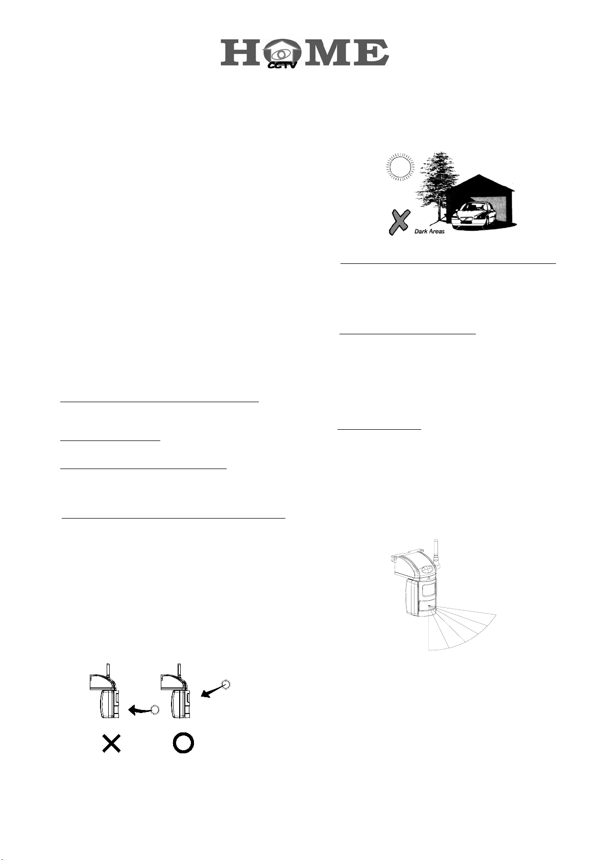
When installing the camera outdoor, you should ensure
that the camera lens will not become dusty easily, and
the camera does not point directly at a light source (e.g.
direct lighting, or sun light) (Fig. 1), as the picture
quality will be impaired. Additionally, the camera must
be positioned so that it will not point directly into the
sun (sunrise or sunset) or any bright light, as this may
cause damage to the camera. The best viewing angle
is achieved at greater heights (e.g. 2.5 to 3m) with the
camera pointing down. Also, avoid viewing areas
where half the area is in bright sunlight and the other
half is dark. (Fig. 2)
Fig. 2
● Test before you mounting your camera permanently. It
is recommended that before mounting your camera
permanently, you temporarily connect your system to
your television or monitor. You can then test your
system and determine the best position for your
camera.
Do not over tighten the camera. Your camera is fully
adjustable both horizontally and vertically via a ball and
socket joint, which is secured with a tension screw.
The tension screw can be locked into position using the
Allen key supplied once your installation is complete.
Do not over tighten as this may stop you from
loosening the screw to make any slight adjustment in
the future. Retain the Allen key for future use.
● Detecting sensitivity: A passive infrared sensor operates
by detecting the objective movement and heat. When
the temperature of the moving object and its
surrounding area are close in value, it may reduce PIR’s
sensitivity. The motion detector’s infrared beams
radiate outward like the slat of a wooden fence. Prior
to mounting, keep in mind that the motion sensor is
more sensitive to the motion that crosses these “slat”,
and less sensitive to the motion that moves directly
towards the sensor.
Your camera has been designed to prevent
condensation when installed outside or in damp
conditions. For this to work correctly the camera
should be left connected to the mains power supply
and switched on permanently.
INSTALLATION
Fig. 1
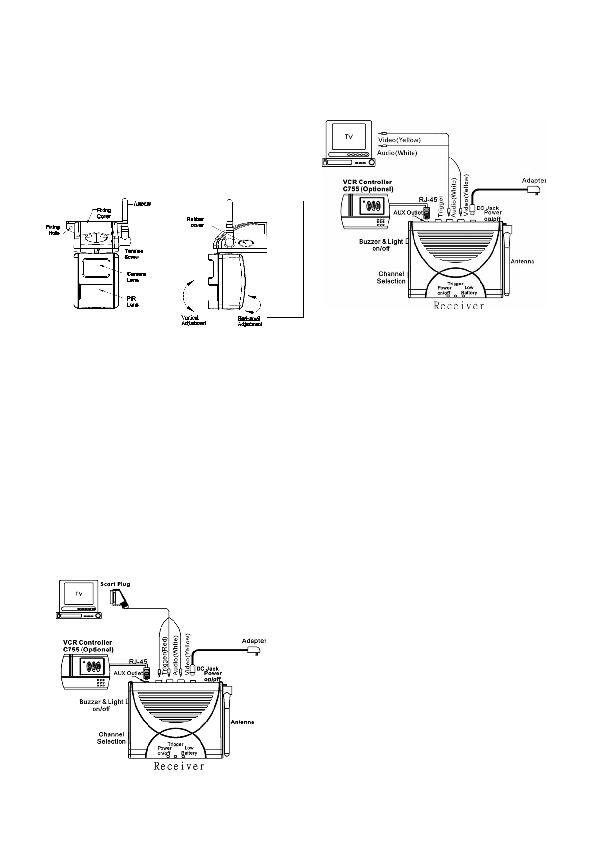
Step 1: Install the PIR camera:
Having tested your camera and being familiar with the
temporary test set, you can assess the best location for the
camera. Ideally you will need one person to hold the
1
camera and another person to look at your television when
adjusting the position.
You can mount the camera on the wall or ceiling according
to your need.
a. Connect the 9VDC 500mA power adapter with the
PIR camera.
b. Use the fixing template provided to mark the
position of the two fixing holes (on the wall or on the
ceiling.) Drill two 4mm-diameter holes at the
marked locations, fully insert the plastic wall plugs
supplied, then thread a supplied screw into each
plug, letting the heads extend about 5 mm from the
wall.
c. Take off the rubber cover on the right side of the
camera bracket.
d. Adjust the Channel Switch knob on the right side of the
camera bracket to set up a channel (channel 1,2,3,4).
And remember which channel you selected.
e. Put the rubber cover back to the right side of the
camera bracket.
Step 2: Install the Receiver Unit
(Two versions available: European and American)
European Version
To connect Receiver to your TV:
1. Plug the 1M Scart connector cable that package
included into your TV.
2. Plug the other end, yellow (video), white (audio) and
red (trigger) RCA connectors into the corresponding
RCA connectors on the Receiver.
American Version
To connect Receiver to your TV:
1. Plug the yellow (video) and white (audio) RCA
connectors into TV socket.
2. Plug the yellow (video) and white (audio) RCA
connectors into the corresponding RCA connectors on
the Receiver.
Step 3: Install option accessory VCR
Controller
By adding the optional VCR Controller (C755) in AUX outlet
of the Receiver will enable the system to automatically
record the images and voices when Camera detects
movement. The VCR Controller will automatically switch
your VCR on to Record for one minute and stop recording.
If re-triggered, resume the same step accordingly. (Please
refer to C755 manual for installation and operation.)
OPERATING INSTRUCTION
1. Buzzer/Light ON/OFF SW: Select “Buzzer/Light SW” at
“ON”. When the PIR Camera is triggered, the Receiver
sounds “Beep” twice in response and the Trigger LED
will flash for 1 minute, subject to channel not being
switched.
Note: Buzzer can be turned off by setting “Buzzer/Light
Sw” at the middle position. When the PIR Camera is
triggered, the Receiver will be mute and the Trigger
LED will flash for 1 minute, subject to channel not being
switched.
2. Connect the Receiver with DC12V power adapter and
set the Receiver in the same channel as that of PIR
Camera.
Note: When turning on the power on the Receiver, it
will respond with one “Beep” and the Power on/off LED
will illuminate steadily.
3. Connect the PIR Camera with the 9V power adapter
and turn on the TV. The Camera images can be
viewed right from the TV. The PIR Camera requires
about 1 minute as warming up duration after
connecting to the power adapter. During this duration,
the PIR Camera will ignore any trigger that may
happen. After the elapse of 1 minute, the PIR Camera
will start detecting.
4. When the PIR Camera is triggered:
4-1 Not switching the channel:
When triggered, the signal of Camera image will
shut down for a while and the Trigger LED on the
Receiver will flash and beep twice, activating the
VCR Controller for recording for one minute.
After the elapse of one minute, the VCR Controller
will stop recording.
2
 Loading...