

C128W S
OLAR CAMERA KIT
Installation and Operating Manual
Introduction
The Solar Camera is designed to economically provide safety,
security, convenience to your home and business. Its solar
panel collects daylight and maintains a charge to the battery of
the camera during daylight hours. A negligible amount of
energy is released by the rechargeable battery to operate the
camera during nighttime.
The components included in the C128W Solar Camera Kit:
1 x Solar Camera with PIR and Solar Panel (Transmitter)
●
● 1 x Audio & Video Receiver
1 x Power Adapter for Receiver
●
● 1 x 3 Feet RCA/SCRT Cable
1 x 6V 1.2A Rechargeable Battery
●
● 1 x 9V Alkaline Battery
1 x Waterproof Rubber Plug
●
● 1 X Remote Control
Caution
Pay attention to the following before you install:
1. Sufficient daylight:
requires constant charge during
daylight hours. Please mount the
camera at the location that can
receive sufficient daylight exposure.
2. Detecting sensitivity:
infrared sensor
operates by detecting
the objective
movement and heat.
When the temperature
of the moving object
and its surrounding
area are close in value, it may reduce
PIR’s sensitivity. The motion detector’s
infrared beams radiate outward like the slat of a wooden fence.
Prior to mounting, keep in mind that the motion sensor is more
sensitive to the motion that crosses these “slats”, and less
sensitive to the motion that moves directly towards the sensor
(see Figure 1 and 2.)
3.Keep a light source during nighttime:
work in total darkness. Please bear in mind the camera's
viewing area must be illuminated with a suitable light source
during nighttime.
Solar panel
A passive
Figure 1
Figure 2
The camera cannot
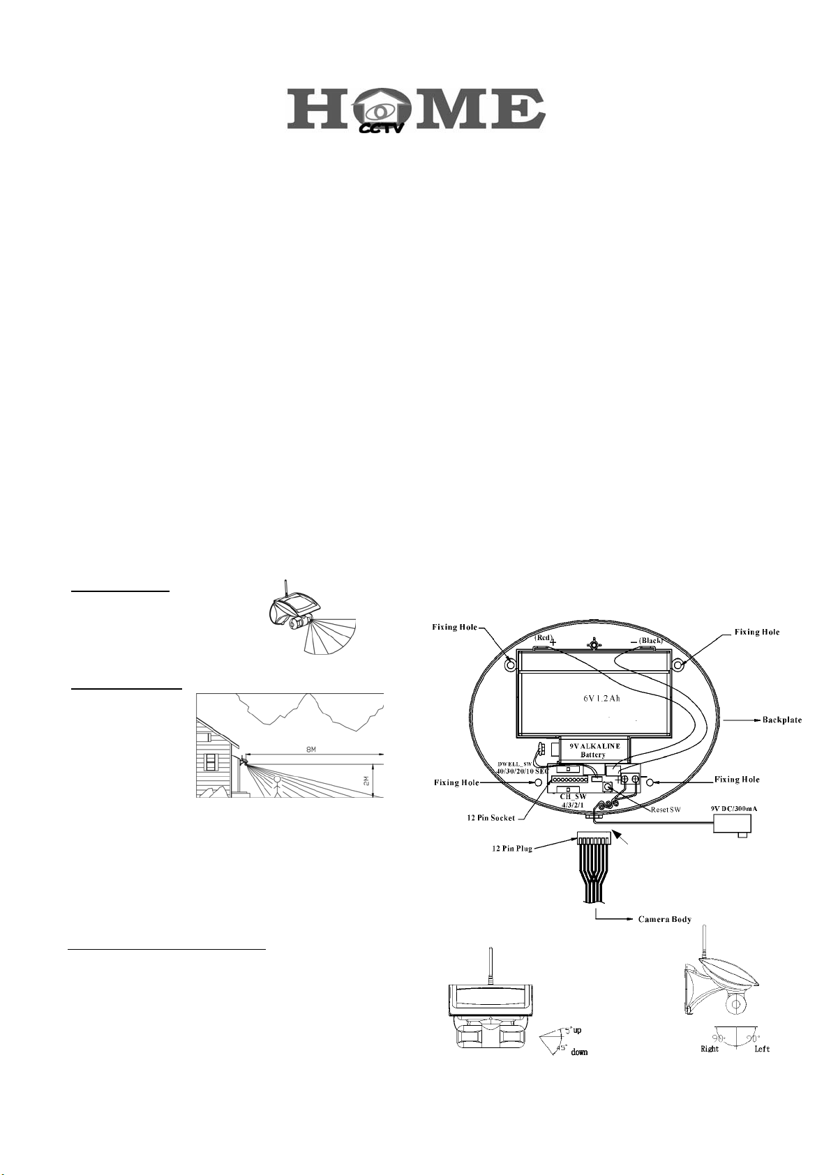
Installation
Step 1: Install the camera (refer to Figure 3)
a. Use the fixing template provided to mark the position of the
four fixing holes. Drill four 5mm-diameter holes.
Mount backplate by inserting two screws into fixing holes on
b.
the top edge of backplate. (All electronic components are
housed within the backplate.)
Adjust the “DWELL_SW(SW3)” knob on backplate to set up
c.
transmission time (lock time) of images and voices. It can be
set as 10,20,30 or 40 seconds.
Adjust the “CH_SW” knob on backplate to set up a channel.
d.
And remember which channel you selected.
Plug the camera’s 12 Pin plug (Cable) into socket on the
e.
backplate, then secure the camera set (front cover) to the
backplate by inserting screws into two fixing holes on the
button edge of front cover and backplate. And then insert
the waterproof rubber plug into the hole at the bottom of
front cover.
The camera and PIR which under the main solar panel
f.
cabinet can be swiveled upward to 5°, downward to
45°(refer to Figure 4) and 90° horizontally (refer to Figure 5)
Adjust the camera and PIR angle according to your need.
g.
1
Figure 4
Waterproof Rubber Plug
Figure 3
Figure 5
In order for the Remote Control to operate with the Camera
h.
both devices must be configured with the same ‘House
Code’.
The House Code is configured by setting the 8 DIP switches,
located on the PCB in the rear of the main camera body, to a
random On/Off sequence. Use the tip of a ballpoint pen or
a small screwdriver to move each switch in turn and ensure
that each switch ‘clicks’ fully into position.
Note: it is recommended that the system House Code is
always reset to a code other than the factory default.
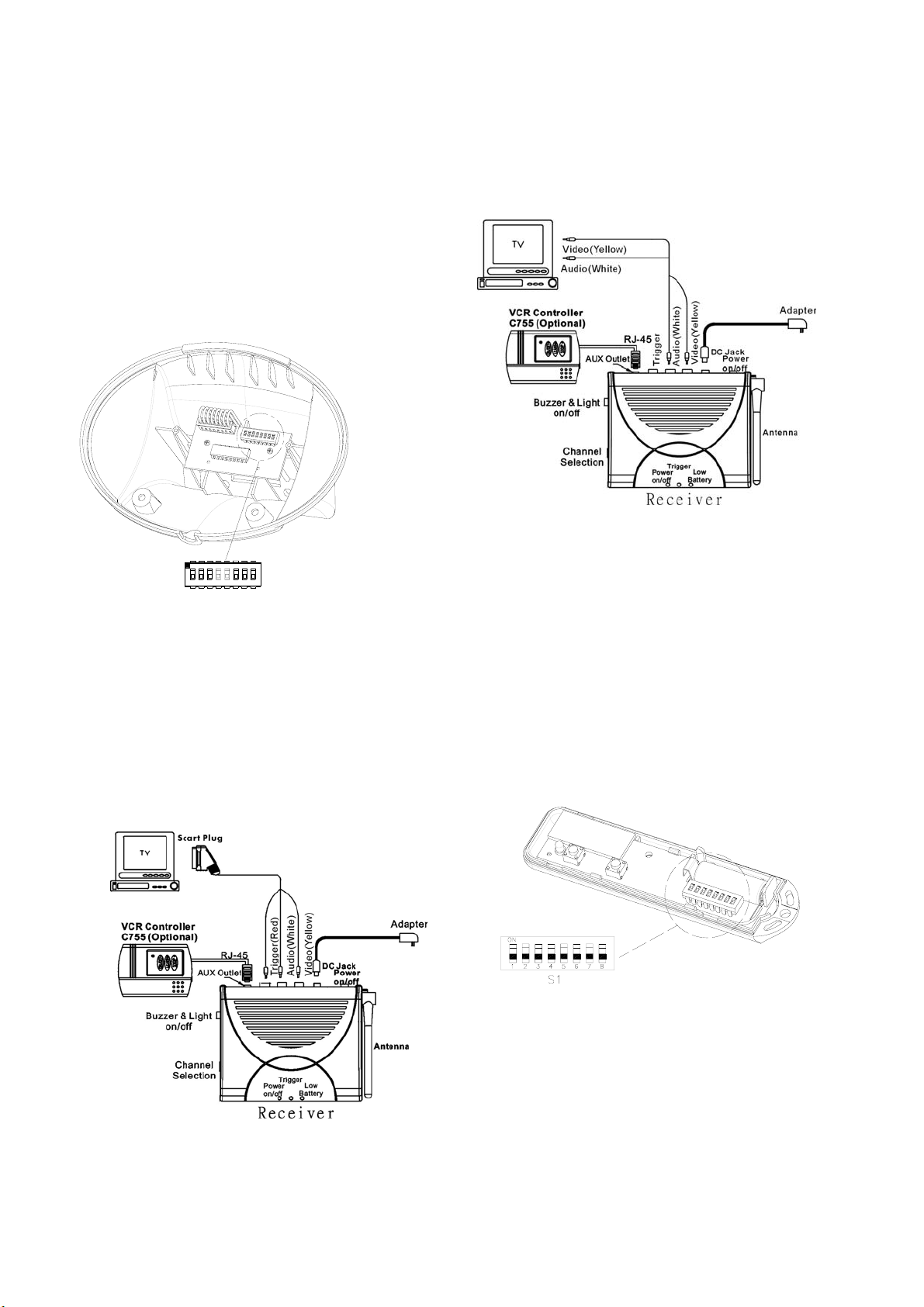
To connect receiver to your TV:
1. Plug the yellow (video) and white (audio) RCA connectors
into TV socket.
2. Plug the yellow (video) and white (audio) RCA connectors
into the corresponding RCA connectors on the receiver.
Figure 7 American Version
ON ECE
68751324
SW1
Step 2: Install Receiver Unit
(Two visions available: European and American)
European Version (refer to Figure 6):
To connect receiver to your TV:
1. Plug the 1M Scart connector cable that
package included into your TV.
2. Plug the other end, yellow (video), white (audio) and red
(trigger) RCA connectors into the corresponding RCA
connectors on the receiver.
Figure 6 European Version
American Version (refer to Figure 7):
Step 3: Install Remote Control
1. Remove the battery cover fixing screw on the rear of the
Remote Control and carefully remove the front cover.
2. Ensure that the House Code setting of the DIP switches in
the Remote Control are set to the same On/Off sequence
as set on the Camera.
3. Insert the battery taking care to observe the correct polarity.
4. Replace the front cover and refit the fixing screw. Do not
over tighten the screw as this could damage the screw
thread in the moulding.
Operating Instruction:
(1) Buzzer/Light ON/OFF SW: Select “Buzzer/Light SW” at
"ON". When PIR camera is triggered, image and voices
will be transmitted. Upon receiving the signals, the receiver
sounds “Beep” twice in response and the LED will flash for
1 minute.
(2) Transmission time (lock time) of image and voices can be
set as 10, 20, 30, or 40 seconds by carefully adjusting the
“DWELL_SW (SW3)” knob of Camera.
(3) When lock time of trigger is over, the camera will continue
2
 Loading...