

AN163 ON/OFF MODULE
This plug-in ON/OFF Module is a transceiver which is a Z-WaveTM enabled device
and is fully compatible with any Z-Wave
devices displaying the Z-Wave
TM
logo can also be used with it regardless of the
manufacturer, and ours can also be used in other manufacturer’s Z-Wave
networks. Remote On/Off control of the connected load is possible with other
manufacturer’s Wireless Controller. Each module is designed to act as a repeater.
Repeaters will re-transmit the RF signal to ensure that the signal is received by its
intended destination by routing the signal around obst acles and radio dead spots.
This plug-in ON/OFF Module is able to detect current wattage (5~1440W) and
overload wattage of connected non-dimmable lights or appliances. When detecting
overload state, the Module will be disabled and its On/Off button will be locked out of
which LED will flash quickly for 30 seconds. However, unplug and re-connect the
Module will reset its overload condition to normal status.
Include to or Exclude from a Z-WaveTM Network
In the front casing, there is an On/Off button with LED indicator which is used to carry
out inclusion, exclusion, reset or association. Toggle On/Off button between On and
Off. When first power is applied, its LED flashes on and off alternately and repeatedly
at 2-second intervals. It implies that it has not been assigned a node ID and cannot
work with Z-Wave enabled devices. Please get familiar with the terms below before
starting the operations.
Function Description
Inclusion Add a Z-Wave enabled device (e.g. On/Off Module) to Z-Wave network.
Exclusion Delete a Z-Wave enabled device (e.g. On/Off Module) from the network.
TM
enabled network. Z-WaveTM enabled
TM
enabled
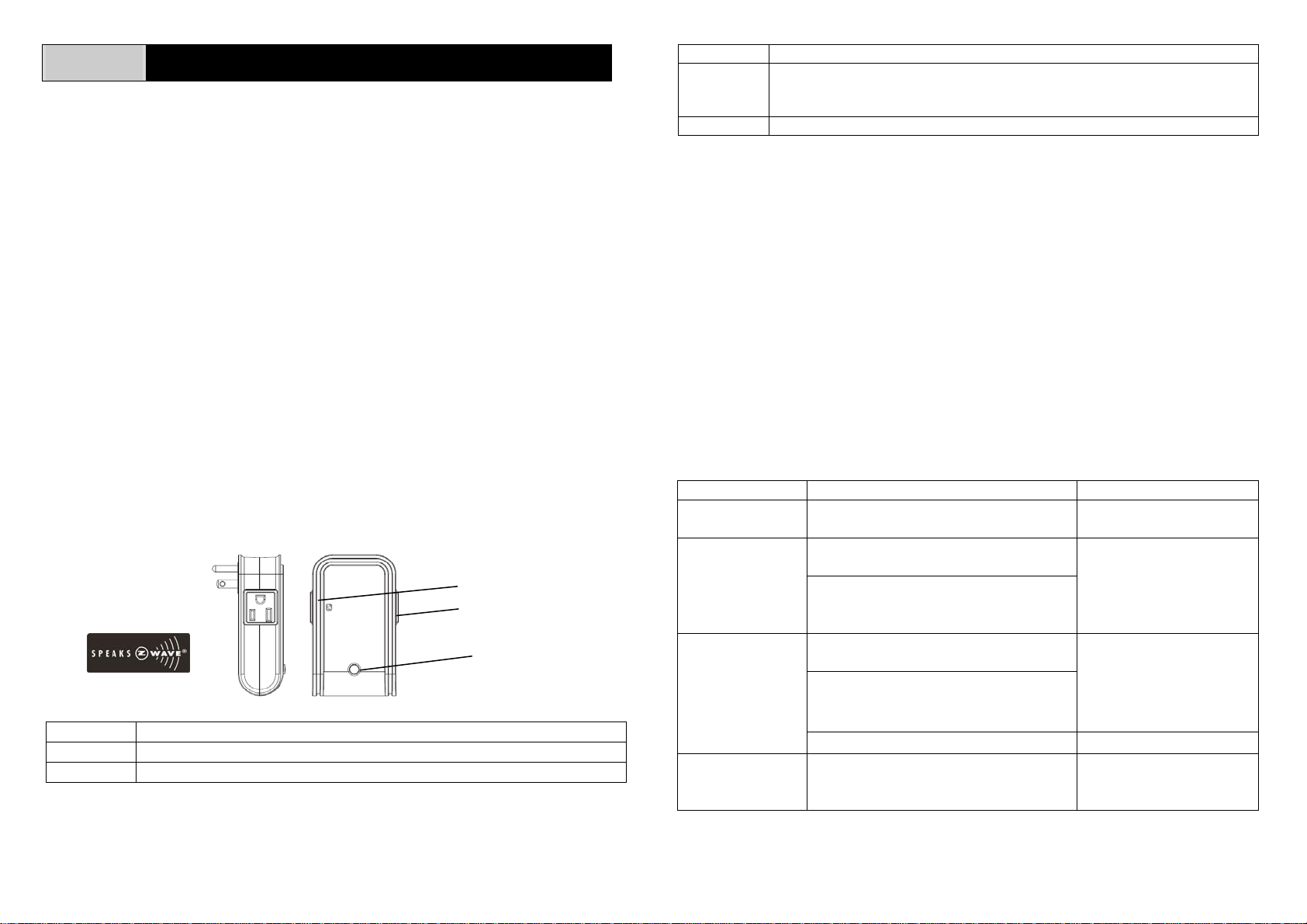
Controllable outlet
Pass-through outlet
On /Off knob
Function Description
Association After inclusion, you have to define the relationship between devices.
Through association, device can be assigned as master/slave, and specif y
which slave is going to be controlled by which master.
Reset Restore On/Off Module to factory default.
The table below lists an operation summary of basic Z-Wave functions. Please refer
to the instructions for your Z-Wave
TM
Certificated Primary Controller to access the
setup function, and to include/exclude/associate devices. The module executes the
function of auto inclusion when…
Auto Inclusion
The function of auto inclusion will be executed as long as the module does not have
a node ID and in situations where…
1. The power is first applied.
2. The execution of exclusion/reset is successful where the stored node ID is
cleared.
Note: Auto inclusion timeout is 4 minutes during which the node information of
explorer frame will be emitted once every 5 seconds. Unlike “inclusion” function as
shown in the table below, the execution of auto inclusion is free from pressing the
tamper switch on the unit.
Function Description LED Indication
No node ID The Z-Wave Controller does not allocate
a node ID to the Module.
Inclusion 1. Have Z-Wave Controller entered
inclusion mode.
2. Pressing On/Off button three times
within 1.5 seconds will enter
inclusion mode.
Exclusion 1. Have Z-Wave Controller entered
exclusion mode.
2. Pressing On/Off button three times
within 1.5 seconds will enter
exclusion mode.
Node ID has been excluded. 2-second on, 2-second off
Reset 1. Pressing On/Off button three times
within 1.5 seconds will enter
inclusion mode.
2-second on, 2-second off
Press On, for on
Press Off, for off
Press On, for on
Press Off, for off
Press On, for on
Press Off, for off
1

2. Within 1 second, press On/Off
button again for 5 seconds until LED
is off.
3. IDs are excluded. 2-second on, 2-second off
Association 1. Have Z-Wave Controller entered
association mode.
Or Pressing On/Off button three times
within 1.5 seconds will enter
association mode
2. There are two groupings - 1 and 2.
Refer to Z-Wave’s Groups as
described on page 3 & 4.
Press On, for on
Press Off, for off
Ensure that the unit is OFF before performing Inclusion/Exclusion/Reset.
Failed or successful results in including/excluding the node ID can be viewed from the
Z-Wave Controller.
LED Indication
To distinguish what mode the Module is in, view from the LED for identification.
State Type LED Indication
Normal Under normal operation, toggle On/Off button between On and
Off. When pressing On, LED lights up, whereas Off, LED is off.
No node ID Under normal operation, when the Module has not been allocated
a node ID, the LED flashes on and off alternately at 2-second
intervals. By pressing On/Off button, it will stop flashing
temporarily. However, after unplugging and reconnecting the
Module, the LED will flash on and off alternately at 2-second
intervals.
Overload When overload state occurs, the Module is disabled of which LED
flashes on and off alternately for 30 seconds at 0.1 second
intervals. Overload state can be cleared by unplugging and
reconnecting the Module to the wall outlet.
Choosing a Suitable Location
1. Do not locate the Module facing direct sunlight, humid or dusty place.
2. The suitable ambient temperature for the Module is 0°C~40°C.
3. Do not locate the Module where exists combustible substances or any source of
heat, e.g. fires, radiators, boiler etc.
4. After putting it into use, the body of Module will become a little bit hot of which
phenomenon is normal.
Installation
1. Plug this On/Off Module into a wall outlet near the load to be controlled.
2. Plug the load into the Module. Make sure the load to be controlled does not
exceed 1440 watts.
3. Press the button or switch on the load to the ON position.
4. To manually turn ON the Module, press and release the On/Off button. The LED
will turn ON, and the load plugged into the Module will also turn ON.
5. To manually turn OFF the Module, simply press and release the On/Off button.
The LED will turn OFF and the load plugged into the Module will also turn OFF.
Programming
1. Basic Command Class / Binary Switch Command Class
The Module will respond to BASIC and BINARY commands that are part of the
Z-Wave system.
1-1 BASIC_GET / BINARY_SWITCH_GET
Upon receipt of the following commands from a Z-Wave Controller, the Module
will report its On/Off state to the Cont roller.
Basic Get Command: [Command Class Basic, Basic Get]
Basic Report Command:
Report OFF: [Command Class Basic, Basic Report, Value = 0(0x00)]
Report ON:[Command Class Basic, Basic Report, Value = (255)0xFF]
Binary Switch Get Command:[Command Class Switch Binary, Switch
Binary Get]
Binary Switch Report Command:
Report OFF:[Command Class Switch Binary, Switch Binary Report, Value
=0(0x00)]
Report ON:[Command Class Switch Binary, Switch Binary Report, Value
= (255)0xFF]
2
 Loading...