

AD150
General Introduction
The In-Wall Dimmer Module is designed to wirelessly control on/off and dimming of light
bulbs. This device is tiny enough to be installed inside an electrical box behind a wall switch.
It also can be connected to the wall switch to allow ordinary manual on/off control. At
220-240V voltage, this module can support up to 300W resistive/ incandescent load, or 200W
fluorescent load.
It supports U-Net two-way wireless technology and is fully compatible with any U-Net enabled
devices. The U-net protocol allows end devices such as AD150 to pair with a U-Net gateway
as central control making it suitable for smart home cloud based platforms such as HomeSys.
In-Wall Dimmer Module
FCC ID: FU5AD150
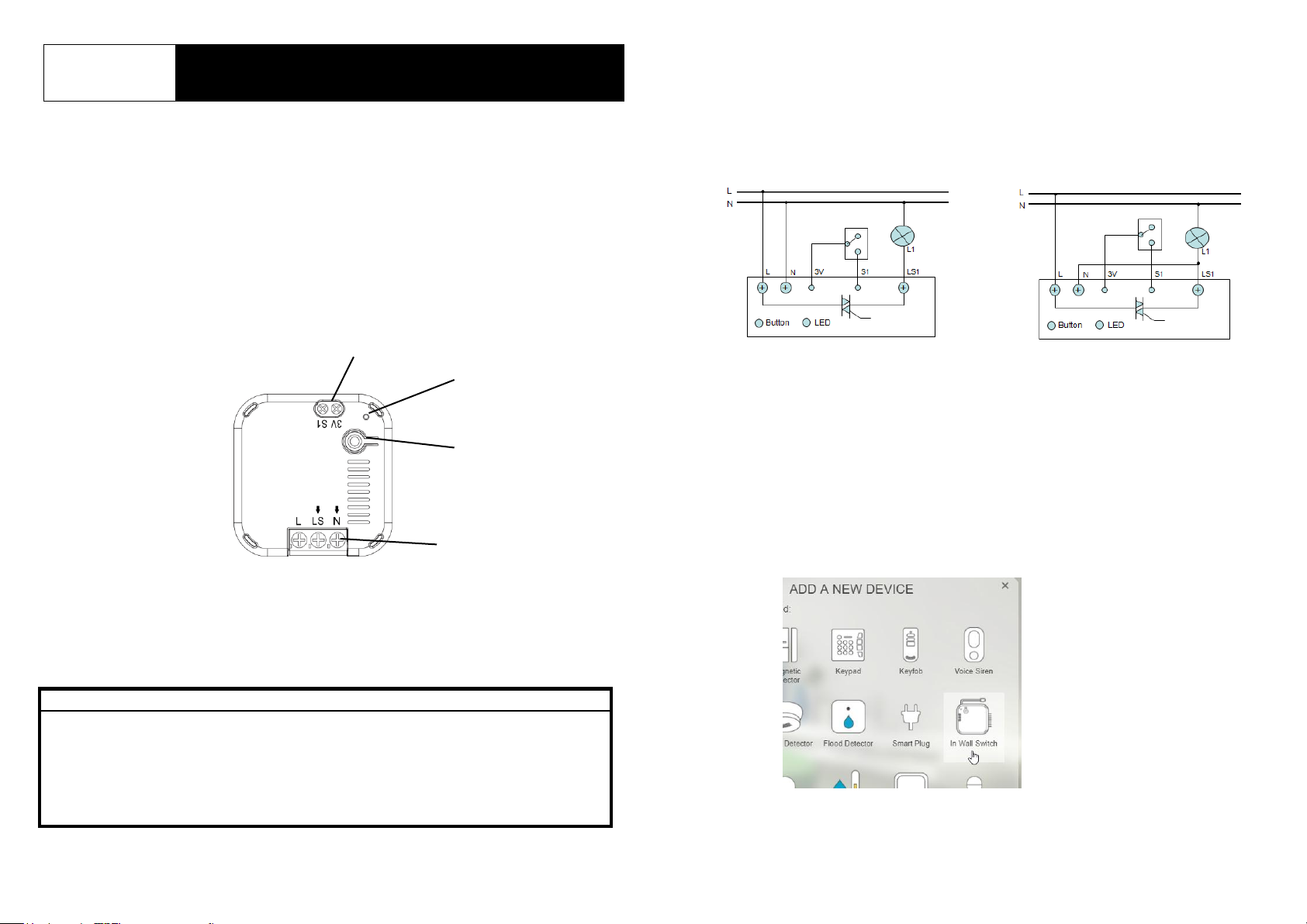
Product Overview
Switch Contact
LED
indicator
Link Key/
Control button
Wiring
Terminals
Safety Precautions before Installation
Be sure to isolate or switch off mains power before installing or maintenance.
Avoid installing the unit in stormy or raining weather.
Do ensure that the power supply circuit is protected by a 16 amp circuit breaker or
suitable equivalent fuse.
IMPORTANT
Installation must be performed by skilled technicians who are informed about the standards
and technical requirements of the appliance and its proper installation. Note that the In-Wall
Dimmer Module is designed to be installed in a wall switch box to operate.
Check your local codes as they apply to your situation. If the house wiring is of aluminum,
consult with an electrician about proper wiring methods.
Before proceeding with the installation, TURN OFF THE POWER TO THE LIGHTING
CIRCUIT AT THE CIRCUIT BREAKER OR FUSE BOX TO AVOID ELECTRICAL SHOCK.
Installation
1. Switch off or isolate the AC mains power before installing.
2. The In-Wall Dimmer Module supports both 3-wire (with neutral wire) and 2-wire (without
neutral wire) connections. The in-wall module should be connected to AC mains and the
load (L1) according to one of the following wiring diagram.
3-wire Wiring Diagram 2-wire Wiring Diagram
Note: By default switch contact S1 supports Single-Pole-Double-Throw (SPDT) type of binary
switch. However, through the setting of Gateway or using the On/Off button, S1 can be
configured to support Tact/Push-button switches as well. Refer to the Operation section.
3. Switch the AC mains power back on to power up the unit.
Binding with HomeSys
4. If the Gateway was powered off, wait until the Gateway is fully powered on and ready for
binding.
5. Log into the HomeSys account from a web browser.
6. Select “System”.
7. Select “Add a New Device”, then “In Wall Switch”.
1
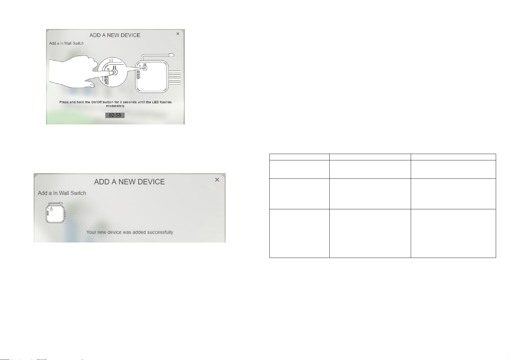
8. The following screen will appear. This means the gateway is entering binding mode.
9. Make sure the LED on the unit is turned off. If it is on, press the Link Key once to turn it
off.
10. Press and hold the Link button on the in-wall module for 3 seconds until its LED turn on
then release. The LED will start to flash.
11. The screen below will appear in 10 seconds if the process is successful and the LED
indicator will stop flashing.
Note: If the LED flashes rapidly 3 times after 30 seconds, this indicates the binding was
unsuccessful. Please refer to the Troubleshooting section.
Operation
The In-Wall module can be operated either remotely through the gateway, manually using a
connected wall switch, or manually through its own Control Button.
Using the gateway:
User can turn on/off and dim* the light bulb. The LED indicator on the module will also turn on
or off accordingly.
Using the external wall switch
For Binary switch :
- User can only turn on/off the light bulb. Diming function is not supported. A message will be
sent to the Gateway each time when the module is manually turned on or off.
For Tact/Push button switch :
- User can turn on/off and dim* the light bulb. A message will be sent to the Gateway each
time the button is pressed. Refer to the Control Button table below to configure the In-Wall
module for this type of switch.
Note: External dimmer type switch is not supported.
Using the Control Button
Refer to the table below:
Action/Status Description LED indicator
Quick press on the Control
On/off
Dimming*
Change switch input
from “binary switch
mode” to “tact switch
mode” or vice versa.
*Note:
- This applies to dimmable type LED bulb only. Attempt to dim a non-dimmable LED bulb will
have unpredictable results and may cause damage to the LED bulb.
-The maximum brightness in 2-wire configuration shall be about 75% of the bulb’s rated
power.
Whenever the module is powered up again, usually after a power-cut, it will send a message
to gateway to report its status.
button to turn on and turn off
the light bulb
When the light is ON, press
and hold the Control button.
The light bulb will dim up and
dim down repeatedly until the
button is released.
When device is OFF, press
“link key” for over 5 seconds
but no more than 8 seconds.
LED on = Light is on
LED off =Light is off
LED remains on.
LED will flash the first time after
3 seconds and flash again after
5 seconds.
If pressed longer than 8
seconds the LED will flash 3
times indicating the change did
not take effect.
2
 Loading...