Everpure MRS-600HE Service Manual

EVERPURE® MRS-600HE HIGH EFFICIENCY REVERSE OSMOSIS (RO) SYSTEM
MINERAL REDUCTION SYSTEM FOR FOODSERVICE APPLICATIONS
INTRODUCTION
The Everpure MRS-600HE High Efficiency RO System is a pre-engineered, preassembled Reverse Osmosis (RO)
solution designed to provide high purity water for multiple applications such as premium espresso, coffee, blended beverages and steam. It combines a number of water treatment technologies into one easy-to-install package, providing superior reduction in total dissolved solids (TDS) which can foul or scale water
using equipment.
Initial System Production
Water production depends on supply water pressure and temperature. See Performance section (page 13) for
normalized production.
Influent Water Characteristics
MRS-600HE EV9970-38 (US Market)
MRS-600HE EV9970-47 (European Market)
MRS-600HE EV9970-50 (Australian Market)
MRS-600HE EV9970-85 (Special Applications - US Market)
Allowable operating range of various water properties within which the MRS-600HE System will function properly.
Total Dissolved Solids (TDS) |
|
pH |
|
Free Chlorine |
|
Turbidity |
|
Iron |
|
Bacterial Quality |
0 – 1,000 ppm (0 – 1,000 mg/l) |
|
5 – 10 |
|
0 – 0.1 ppm (0-0.1 mg/L) |
|
0 – 1 NTU |
|
0 – 1.0 ppm (0-1.0 mg/L) |
|
Potable |
|
|
|
|
|
||||||
|
|
|
|
|
|
|
|
|
|
|
NOTE: The MRS-600HE System does NOT include on-board particulate or organic reduction filtration. Incoming water supplies that do not meet the influent water characteristics requirements will require the addition of pretreatment equipment prior to the MRS-600HE System. Do not connect the MRS-600HE System after any other water filtration system, unless specifically provided or specified. System performance may be affected if requirements are not met, including system output and cartridge changeout frequency.
The system consists of five major components:
1. |
Everpure 2SR-BW Water Conditioning Cartridge* |
4. |
6-Gallon (22.7 l) RO water storage tank |
2. |
Dual-head booster pump |
5. |
Control system with power supply |
3.Everpure MR-600, MR-600-1 or MR-600F Reverse Osmosis (RO) Membrane Cartridge
The Everpure 2SR-BW Water Conditioning Cartridge contains media that reduces the scaling tendency of hard water minerals found in many water supplies, extending RO membrane life.*
The dual-head booster pump increases the inlet pressure to maintain consistent permeate production, plus eliminates back-pressure on the permeate output. This innovative approach to both boosting and eliminating back-pressure maximizes system efficiency.
The Everpure MR-600, MR-600-1 or MR-600F RO Membrane Cartridge contains a semi-permeable reverse osmosis membrane. It’s here that most of the dissolved impurities are separated from the water and flushed down the drain. The water that is able to pass through the membrane, which is very low in dissolved impurities, is referred to as permeate, RO water, or product water.
Once the RO water is produced, it is stored in the 6-gallon (22.7 l) RO water storage tank. This tank serves two (2) key functions;
1)it acts as a buffer between the system and the connected equipment, providing ample volumes of water instantaneously,
2)it reduces the on-off cycling of the RO system which produces better quality water and prolongs the system’s life.
*Everpure 2SR-BW Water Conditioning Cartridge not performance tested or certified by NSF.
|
|
|
FILTRATION & PROCESSING SOLUTIONS |
EVERPURE MRS-600HE-II SYSTEM ORIGINAL INSTRUCTIONS |
|

SAFETY INSTRUCTIONS
The appliance is only to be installed in locations where its use, maintenance and cleaning is restricted to trained adult personnel. No one should play with the appliance.
The appliance is intended to be permanently connected to the water mains and not connected by a hose-set.
The appliance is not suitable for installation in an area where a water jet could be used and must not be cleaned by a water jet.
Prior to performing any service on a pressurized vessel/tank, eye protection, ear protection and other suitable personal protection equipment should be worn. Isolate the water system and de-pressurize it. Drain the water that is inside the tank by opening the drain valve or by other means. Once the water has been drained , relieve the air pressure by depressing the pin on the Schrader valve.
Grounding Instructions: This appliance must be grounded. In the event of a malfunction or breakdown, grounding will reduce the risk of electric shock by providing a path of least resistance for electric current. This appliance is equipped with a cord having an appliancegrounding conductor and a grounding plug. The plug must be plugged into an appropriate outlet that is installed and grounded in accordance with all local codes and ordinances. If the supply cord is damaged, it must be replaced by the manufacturer, its service agent or similarly qualified persons in order to avoid a hazard.
Improper connection of the appliance-grounding conductor can result in a risk of electric shock. Check with a qualified electrician or service representative if you are in doubt whether the appliance is properly grounded. Do not modify the plug provided with the appliance; if it will not fit in the outlet, have a proper outlet installed by a qualified technician.
INSPECTION
The MRS-600HE System includes all the necessary fittings for installation. Lengths of 3/8" (9.5 mm) tubing have been provided for connecting to the wastewater / drain connection. Supply lines and distribution piping / tubing are not included.
The MRS-600HE System is packaged as a complete unit in one carton. At a minimum, you should have the following:
|
Parts |
Quantity |
1. |
Plate mounted processor assembly |
|
1 |
||
|
Dual-head pump |
|
|
Cartridge heads |
|
|
Controller & power supply |
|
|
Storage tank |
|
2. |
Wall mount bracket |
1 |
3. |
MR-600, MR-600-1 or MR-600F RO cartridge |
1 |
4. |
2SR-BW cartridge |
1 |
5. |
Parts Kit |
1 |
|
|
|
Inspect the carton for damage. Carefully unpack and inspect each item. Report any damage to freight carrier immediately and retain all packaging materials.
SELECTING A LOCATION
Locate the system in an area that is convenient to the inlet water supply and drain facilities, with access for routing the product water tubing / piping to the equipment. Install in a dry location, away from all forms of corrosive and / or flammable materials. Consider ease of access for servicing when selecting a location. Evaluate the mounting surface for its ability to properly support the weight of the processor when in operation [Approximately 90 lbs. (40.8 kg.)].
2 EVERPURE MRS-600HE-II SYSTEM ORIGINAL INSTRUCTIONS

OPERATING SPECIFICATIONS
•Dynamic Operating Pressure: 25 – 80 psi (1.7 – 5.5 bar, 0.17 – 0.55 MPa)
[Pressure below 50 psi (3.4 bar, 0.34 MPa) may affect blend system performance]*
•Maximum Static Pressure: 100 psi (6.9 bar, 0.69 MPa)
•Operating Temperature: 40 – 100°F (4.4 – 37.8°C)
•Plumbing Connections:
Inlet / Outlet: 3/8" (9.5 mm) OD tube (“push-in” quickconnect), 3/8” (9.5 mm) barb or 1/2” (12.7 mm) barb Reject: 3/8” (9.5 mm) OD tube (“push-in” quickconnect)
Tank Drain: 3/8" (9.5 mm) OD tube (“push-in” quick-connect)
* Blend system not performance tested or certified by NSF®.
TOOLS, MATERIALS & SPECIAL EQUIPMENT REQUIRED
•Electrical - Rated Voltage & Power Cord Plug Type: System Part No. EV9970-38, EV9970-85: 100 – 120VAC/50 – 60Hz - NEMA 5 – 15P
System Part No. EV9970-47: 220 – 240VAC/50 – 60Hz - CEE 7/7 System Part No. EV9970-50: 220 – 240VAC/50 – 60Hz - AS 3112
•Power Input:
Standby: 25 Watts (25W) Flush: 60 watts (60W) Run / Fill: 210 Watts (210W)
•Branch Circuit Protection:
10 AMP (10A) Minimum. To minimize personnel shock hazards, install on a GFI, RCD, or equivalent protected circuit.
In most cases, common hand tools and plumbing materials suitable for use with RO water are all that is needed for installing the system. The system setup and calibration requires special equipment:
•Compressed air supply 60 psi (4.1 bar, 0.41 MPa) minimum with Schrader® style air chuck and pressure gauge
•Two (2) - 32 ounce or 1,000 ml graduated containers
•Stopwatch
•TDS meter
•Utility knife
•Eyedropper
•5.25% household bleach or equivalent disinfectant
NOTE: Please read this entire manual prior to installing and operating the system.
NOTE: Consult with your local building inspector for approval and required permits to install this system. Additional equipment such as backflow prevention devices, seismic restraint equipment, air gaps, etc., may be required. Installation must meet all local and national codes.
PRE-INSTALLATION CHECKLIST
1.Can the unit be mounted within a reasonable distance of the water supply and drain facilities?
2.Is there an un-switched receptacle available for powering the system?
3.Is there adequate clearance and support to install the unit and permit access for maintenance? The total system weight will vary based on model and storage tank selected. See Dimensions and Operating Weights (page 13) for approximate operating weights.
4.Does the inlet water supply meet the requirements listed in the table under Influent Water Characteristics (page 1)?
5.Is there a minimum of 25 psi (1.7 bar, 0.17 MPa) pressure on a consistent basis?
SYSTEM ASSEMBLY
 Do not use screws smaller than #12 (5.5 mm) for mounting the processor.
Mounting surface may require reinforcement to support processor safely. Hollow walls, drywall and other non-structural surfaces are not suitable unless reinforced.
Processor Assembly Mounting
1.The MRS-600HE System has been provided with a wall mount bracket to allow greater installation flexibility and ease of processor placement. If the wall mount bracket is not suitable for this specific application, the processor backplate has four (4) mounting holes [two (2) keyhole slots, two (2) standard] on 16" (406.4 mm) centers for securing it directly to a vertical surface.
2.Refer to Figure 9 (page 18) for dimensional information. Use this as your guide to determine the wall mount bracket and / or processor location. If NOT installing the wall mount bracket, go to step 5.
3.Refer to Figure 1 (next page) for mounting bracket details. Position the top row of holes 19⁄16" (39.7 mm) above the top of the processor when installed. Install the wall mount bracket to a suitable vertical surface. Use no less than four (4)- #12 (5.5 mm) fasteners to secure the bracket to the surface.
EVERPURE MRS-600HE-II SYSTEM ORIGINAL INSTRUCTIONS |
3 |

SYSTEM ASSEMBLY, continued
Figure 1. Wall Mount Bracket.
Position top row of mounting holes 19⁄16" (39.7 mm) above the top edge of backplate.
|
20.0 |
508 |
|
|
|
|
17.8 |
452 |
|
|
|
|
16.6 |
422 |
|
|
|
|
15.4 |
391 |
|
|
|
|
14.2 |
361 |
|
|
|
3.1 |
80 |
4.2 |
107 |
5.0 |
127 |
16X .33 8.4 THRU
4.Prepare to attach the processor to the wall mount bracket. Lift the processor and “hook” the metal lip of the processor backplate over the lower lip of channel on the wall mount bracket. Go to step 6.
5.Measure and install two (2)- #12 (5.5 mm) minimum fasteners on 16". (406.4 mm) centers to engage the top edge of the processor backplate, leaving a 1/4" (6.4 mm) gap. Lift the processor and “hook” the keyhole slots on the processor backplate. Tighten the two (2) fasteners.
6.Install two (2)- #12 (5.5 mm) minimum fasteners in the 2" (50.8 mm) wide slots along the bottom edge of the processor backplate.
Piping / Tubing Connections
1.Refer to Figures 2 (below) and 10 (page 19) for general arrangement views of the piping, with a description of major components and connection points. These major components and connections will be referred to in the following steps.
2.A parts kit has been provided, which includes valves and tees to configure a system bypass. Assemble the parts to the system using the example shown in Figure 2 (below).
Figure 2. MRS-600HE System Assembly
|
|
|
|
|
|
|
|
|
|
||
|
|
|
|
|
|
|
|
Low TDS Outlet |
|||
|
|
|
|
|
|
(Steam Equipment) |
|
||||
|
|
|
|
|
|
|
|
|
|
|
|
Inlet |
|
|
|
|
|
|
|
|
|
|
Reduced TDS Outlet |
|
|
|
|
|
|
|
|
||||
(From Filter System |
|
|
|
|
|
|
|
|
|
|
(Coffee, Espresso, Combi-Oven |
|
|
|
|
|
|
|
|
|
|
|
|
|
|
|
|
|
|
|
|
|
|
|
|
|
|
|
|
|
|
|
|
|
|
|
|
MRS-600HE |
System |
2SR-BW
Conditioning Cartridge
|
MR-600, MR-600-1 or |
RO Reject |
Storage Tank Drain |
3/8" (9.5 mm) OD Push-In |
|
MR-600F RO Cartridge |
|
|
3/8" (9.5 mm) OD Push-In |
|
|
Floor Drain. Maintain air gap per local and national codes
4 EVERPURE MRS-600HE-II SYSTEM ORIGINAL INSTRUCTIONS

SYSTEM ASSEMBLY, continued
3. Prepare the plumbing to accept the RO system.
Note: The product water tubing / piping and associated fittings connecting the RO product outlet to the equipment being serviced should be food-grade material that meets NSF® Standard 51, 61, or similar, with a minimum pressure rating of 100 psi (6.9 bar, 0.69 MPa). The product water may react with metal piping, creating a corrosive condition in addition to imparting an objectionable taste. Plastic pipe or reinforced beverage tubing are generally very good material choices for RO water distribution piping. The size of the product water tubing / piping should be 3/8" (9.5 mm) ID minimum. Distances of 25 feet (7.6 m) or greater from the RO system to the equipment being serviced should be 1/2" (12.7 mm) ID minimum.
4.Shut off the supply of water to the new or existing filtration system and relieve pressure. Connect a line from the treated water outlet of the filtration system to the inlet of the MRS-600HE System.
5.Connect the appropriate size and type of tubing / piping and associated fittings to the corresponding MRS-600HE System outlet connection. Route the line(s) to the equipment being serviced (i.e.; steam, espresso, coffee, etc.). Close the inlet, outlet and bypass valves. Apply pressure to the existing filtration system and place it back into service.
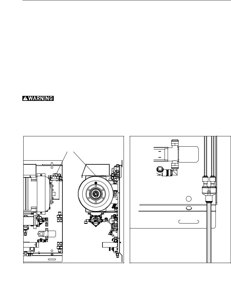
6.For safety in transit, the storage tank is shipped without a precharge. Locate the Schrader® valve on the storage tank and precharge to 48 – 50 psi (3.3 - 3.4 bar, 0.33 - 0.34 MPa) with a source of clean, dry air. See Figure 3 (below).
7.Connect a 3/8" (9.5 mm) OD tube to the reject Y-connector (labeled WASTE) located in the lower right corner of the processor. Route the other end of the tubing to a drain nearby, securing it properly. Allow an air gap at the drain, following any applicable local and national codes. See Figures 2 (page 4) and 4 (below).
Refer to “Reject to Drain, Maximum” under "RO Production in the Performance Table" (page 10) to determine the maximum reject (waste) flow rate. Verify the drain has ample capacity for this waste flow, plus all other sources of waste flow sharing this drain.
Figure 3. Precharging Storage Tank |
Figure 4. Reject Y-Connector Detail |
“Schrader” Valve Location
Charge to 48 – 50 psi (3.3 – 3.4 bar, 0.33 - 0.34 MPa) with clean, dry air.
Waste
Connect waste line to Y-connector and route to drain. Maintain air gap  per local and national codes.
EVERPURE MRS-600HE-II SYSTEM ORIGINAL INSTRUCTIONS |
5 |

CONTROL SYSTEM OPERATION
The MRS-600HE System includes a microprocessor based control system that monitors system conditions and controls the system operation. A digital display panel provides operational information and three (3) buttons provide operator access. To follow is a list of modes and a description of each function. Use this as a guide during startup, normal operation and when service is required.
Operational Mode
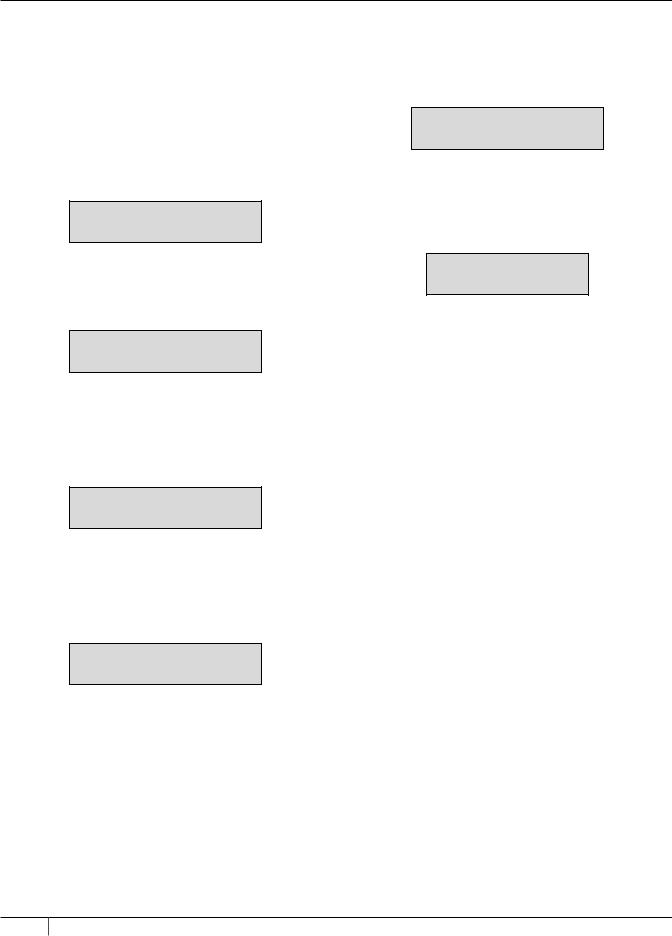
•INITIAL POWER-UP: When power is first applied to the system, the panel will display the system identification with software version. After several seconds, it will automatically transition to the MAIN SCREEN VIEW.
FIRMWARE 4.08
If the RO water pressure drops below the minimum allowable pressure setting during DEEP FLUSHING, the control will terminate the DEEP FLUSHING process and remain idle until water is drawn. Once water is drawn, the system returns to normal operation as described in “PRESSURIZE” mode above.
RE-PRESSURIZE...
XXX PSI (BAR)
•PRESSURE LIMIT WARNING: This message indicates a fault with the pressure sensing circuit or the detection of pressure exceeding 114 psi (7.9 bar, 0.79 MPa). See Troubleshooting Guide on page 15 for guidance on how to correct this condition.
•MAIN SCREEN VIEW: When the system is in normal operation and not operating in any of the following operational modes, the panel will display the storage tank water pressure.
PRESSURE XXX PSI (BAR)
•PRESSURIZE: When pressure in the storage tank drops below the pressure “on” setting, the system will start processing water and refill the storage tank. Once the pressure in the storage tank rises above the pressure “off” setting, the system will stop. Storage tank water pressure will be displayed.
PRESSURIZE...
XXX PSI (BAR)
•DEEP FLUSHING: If the MRS-600HE System remains idle for the programmed length of time, the control system will automatically go into DEEP FLUSHING mode. During this time, there will be flow to drain (reject). Remaining flush time in seconds and storage tank water pressure will be displayed.
DEEP FLUSHING...
XXXXS XXX PSI (BAR)
•RE-PRESSURIZE: At the start of the DEEP FLUSHING operation, the system will repressurize to the normal tank full pressure, then begin DEEP FLUSHING. Storage tank water pressure will be displayed.
Under normal conditions, the pressure in the storage tank will remain above the minimum allowable flush pressure throughout the DEEP FLUSHING operation.
Once the DEEP FLUSHING operation ends, the system returns to normal operation, but will not PRESSURIZE until the storage tank water pressure drops below the minimum allowable flush pressure. Once it runs and fills, the system returns to operating within the normal “on” and “off” pressure settings.
PRESSURE LIMIT
WARNING
Programming Mode
The controller has several user accessible menus. This menu “loop” allows for adjustment of several variable parameters. The Controller has three (3) buttons below the display for these adjustments. In most cases, a description of the button function is shown in the digital display area.
Once you enter the programming mode, the controller will save your last entry upon pressing ENTER. If an adjustment is made without pressing ENTER, the controller returns to the main screen and the adjustment will not be saved. If a key is not depressed for about 25 seconds, the controller exits programming mode and returns to the operational mode.
•Press and hold any key for three (3) seconds to enter programming mode.
•II – Press the middle key to advance to “FLUSH TIME: XXX S” screen. Press left or right key to advance to “PRESSURE UOM: XXX” screen.
•PRESSURE UOM: XXX - This parameter determines whether psi or BAR will be the unit of measure used to display the storage tank water pressure. Use the +/- keys to adjust this value. Press ENTER to save the selected value and advance to the next screen.
•TANK FULL P: XXX - This parameter determines the pressure at which RO water production will stop, or turn “off”. This setting is normally 100 psi (6.9 bar, 0.69 MPa). Range is 70 – 100 psi (4.8 – 6.9 bar, 0.48 - 0.69 MPa) in five
(5) psi (0.3 – 0.4 bar, 0.03 - 0.04 MPa) increments. Use the +/- keys to adjust this value. Press ENTER to save the selected value and advance to the next screen.
•START DIFF.: XXX - This parameter determines the pressure differential between the RO water production start (“on”) pressure and stop (“off”) pressure. This setting is normally 20 psi (1.4 bar, 0.14 MPa). Range is 10 – 25 psi (0.7 – 1.7 bar, 0.07 - 0.17 MPa) in five (5) psi (0.3 – 0.4 bar, 0.03 - 0.04 MPa) increments. Use the +/- keys to adjust this value. Press ENTER to save the selected value and advance to the next screen.
6 EVERPURE MRS-600HE-II SYSTEM ORIGINAL INSTRUCTIONS
 Loading...