

Everpure MRS-100, MRS-225CC, MRS-350CC, MRS-225, MRS-350 Installation And Operation Manual
...
Installation and Operation Guide
INTRODUCTION
The Everpure MRS (Mineral Reduction System) is a pre-engineered,
pre-assembled Reverse Osmosis (RO) system designed to provide
high purity water for many applications, such as premium espresso,
coffee and blended beverages, to name a few. It combines a
number of water treatment technologies into one easy to install
package. The system provides superior protection against taste and
odor causing contaminants while removing dirt, particulates and
dissolved solids that can foul or scale equipment.
Initial System Production
Water production depends on supply water pressure and temperature.
See PERFORMANCE section (page 5) for normalized production.
Influent Water Characteristics
The following table lists the allowable operating range of various
water properties within which the MRS will function properly.
Total Dissolved Solids (TDS) 0-150 0 PPM (0-150 0 mg/L)
Hardness 0-10 grains (0-171 ppm)
pH 5-10
Chlorine
Chloramines 0-3 PPM (0-3 mg/L)
Tur bid it y 0-1 NTU
Iron 0-1 PPM (0-1 mg/L)
1
Reverse osmosis membrane lter used in this system will be damaged by chlorine. An
activated carbon lter has been provided with this system to protect the reverse osmosis
membrane from chlorine attack. Inuent chlorine should not exceed 3 mg/L.
The complete MRS consists of 5 major components:
The optional 5-micron pre-filter removes suspended particles,
which can lead to premature plugging of the TO and/or RO
membrane cartridge. The TO car tridge removes most oxidizers, but
mainly reduces chlorine, preventing damage to the RO cartridge.
The RO cartridge contains a semi-permeable reverse osmosis
membrane. Here, most dissolved impurities are separated from the
water and flushed down the drain. The water that is able to pass
through the membrane, which is very low in dissolved impurities, is
referred to as permeate, RO water, or product water. Depending on
the model, the permeate will do one of the following:
Systems without calcium carbonate (CC) cartridge - The permeate t
will pass through the cartridge head with by-pass plug, exiting to
service and/or enters the optional storage tank.
Systems with calcium carbonate (CC) cartridge - The permeate t
will pass through calcium carbonate cartridge, where remineralization occurs. This cartridge reintroduces a metered
amount of minerals into the RO permeate. After remineralization,
the treated water exits to ser vice and/or enters the optional
storage tank.
MRS-350BL Model Only - The permeate will flow into the submicron filtration car tridge head. A metered amount of tap water will
mix with this permeate, and this blended water will pass through
the sub-micron filter. Once filtered, the water exits to service and/or
enters the optional storage tank.
1
0-3 PPM (0-3 mg/L)
Inlet booster pump.1.
5-Micron Pre-filter (optional).2.
Granular Activated Carbon Taste & Odor (TO) cartridge.3.
Reverse Osmosis (RO) membrane cartridge.4.
Calcium carbonate (CC) re-mineralization cartridge (CC models 5.
only), or BW 4400 Sub-micron filtration cartridge (BL models only).
MRS-100, MRS-225, MRS-350, MRS-100CC,
MRS-225CC, MRS-350CC, MRS-350BL
Reverse Osmosis Mineral Reduction System For Foodservice Applications
The optional storage tank stores water that has been produced by
the RO System. This provides a water supply “buf fer”, enabling the
system to provide reasonable volumes of product water during high
demand periods.
OPERATING SPECIFICATIONS
Dynamic Operating Pressure: 25– 80 psi (1.7–5.5 bar)t
Static Operating Pressure: 100 psi (6.9 bar)t
Operating Temperature: 40–100°F (4.4–37.8°C)t
Plumbing Connections: t
Inlet /Outlet: 3/8" (9.5 mm) OD tube (“push-in” quick-connect)
Concentrate: 1/4" (6.4 mm) OD tube (“push-in” quick-connect)
Electrical (not field selectable): t
115 VAC/60Hz (US Nema 5-15P Plug)
230VAC/50Hz (European “Schuko” CEE 7/7 Plug)
240VAC/50Hz (Australian AS 3112 Plug)
Branch Circuit Protection: 10 AMP Minimum. To minimize personnel
shock hazards, install on a GFI, RCD, or equivalent protected circuit.
Disconnect Device: The socket-outlet shall be installed near the
equipment and shall be easily accessible
Pre-Installation Checklist
Can the unit be mounted within a reasonable distance of the water 1.
supply and drain facilities?
Is there an un-switched GFIC (ground fault interrupter circuit) 2.
protected receptacle available for powering the system?
Is there adequate clearance and support to install the unit and 3.
permit access for maintenance? The total system weight will vary
based on model and storage tank selected. See specification table
for approximate operating weights.
Does the inlet water supply meet the requirements in the tables 4.
above?
EV3123-42 Rev C OC12

Inlet
(without optional Pre-filter)
Pre-filter
(optional)
Outlet
6TO-BW or 7TO-BW
Carbon Cartridge
MR-100, 225 or 3 50
RO Car tridge
7CC-BW or BW 44 00
Cartridge (optional)
To Storage
Tan k
(not shown,
not
included)
RO Reject
1/4" (6.4 mm)
John Guest)
route to drain
Figure 1. Back view of Prefilter bracket.
Wing
bracket
Prefilter bolts
Figure 2. MRS Assembly.
2
Inlet
(with Pre-filter)
NOTES:
Please read this manual prior to installing and operating the system. t
For incoming water supplies that do not meet the influent water t
characteristics outlined on page 1, additional pre-treatment prior to
the system may be needed. System performance may be affected if
requirements are not met, including system output production and
cartridge change-out frequency.
If the supply pressure exceeds 80 PSI (5.5 bar), install a pressure t
reducing valve. Adjust the pressure reducing valve to the required
operating pressure, not to exceed 80 PSI (5.5 bar).
Consult with your local building inspector for approval and t
required permits to install this system. Additional equipment, such
as back-flow prevention devices, seismic restraint equipment, air
gaps, etc., may be required. Completed installation must meet all
local and national codes.
Do not connect the MRS system after any water filtration system,
unless specifically provided for use with the MRS.
UNPACKING AND INSPECTION
The MRS includes all the necessary fittings for installation. Lengths
of 1/4" (6.4 mm) tubing have been provided for connecting to the
wastewater/drain connection. Supply lines and distribution piping/
tubing are not included.
The MRS system is packaged as a complete unit in two cartons. At a
minimum, you should have the following:
Carton 1 - Plate Mount Processor Assembly Including:
Pump systemA.
Cartridge heads B.
Transformer, pressure switch & gaugesC.
Carton 2 - Cartridge Kit including:
6TO-BW or 7TO-BW cartridgeA.
MR-100, 225 or 350 RO cartridge B.
7CC-BW Calcium carbonate (CC) cartridge (optional), or C.
BW 4400 Cartridge (optional)
Inspect the cartons for damage. Report any damage to freight
carrier immediately. Carefully unpack each item. Save the packaging
material temporarily, as it may be used to protect painted sur faces
during assembly.
SYSTEM ASSEMBLY
The MRS is configured as a two piece unit; with the processor
mounted on a vertical surface and the storage tank located nearby.
Locate the system in an area that is convenient to the inlet water
supply and drain facilities, with access for routing the product water
tubing/piping to the equipment. Install in a dry location, away from
all forms of corrosive and/or flammable materials. Consider ease of
access for servicing when selecting a location.
Processor Assembly Mounting
If the optional Pre-filter has been supplied, go to step to 2. If not 1.
supplied, go to step 5.
Position the MRS processor assembly so the rear of the mounting 2.
plate is accessible. Secure the wing bracket to the rear of the
mounting plate as shown Figure 1. Use the 5/16" hex bolts and
washers provided. Align the wing bracket so it is inward and
upward as far as possible – use a combination square to maintain
alignment. Tighten both bolts securely.
Attach Pre-filter head to Pre-filter bracket with 5/16” hex bolts, 3.
nuts and washers provided.
Insert elbow fitting into solenoid valve inlet. Connect 3/8" (9.5 mm) OD 4.
tubing between pre-filter outlet and elbow fitting on solenoid valve.
The processor framework has 6 mounting holes (3 keyhole slots, 5.
3 standard) on 5.5" (139.7 mm) centers for securing to a stationary
vertical surface. Evaluate the mounting surface for its ability to
properly support the weight of the processor, approximately 40
lbs. (18.1 kg.), when in operation.
Atta6. ch processor to the vertical surface with screws and
anchors designed for the mounting surface material.
continued on the next page . . .
By-pass Plug
(Remove if optional
7CC-BW or BW 44 00 cartridge are provided)
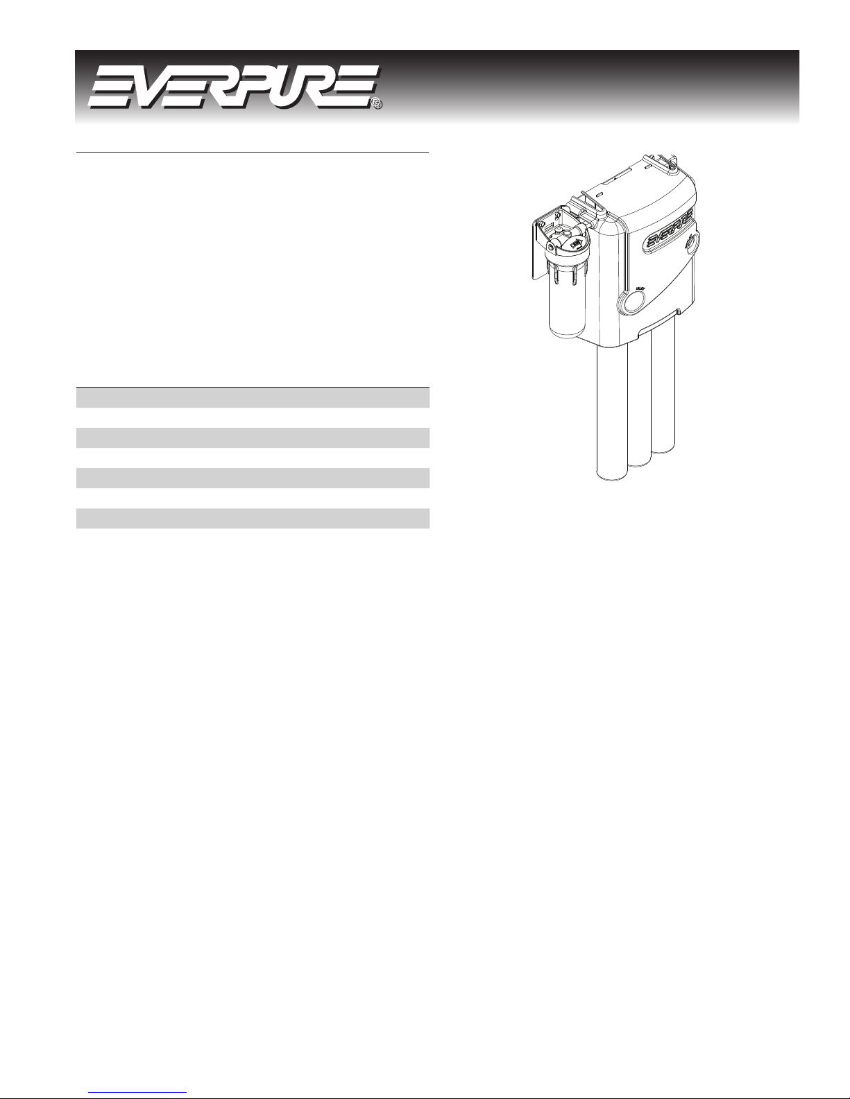
MRS
Processor
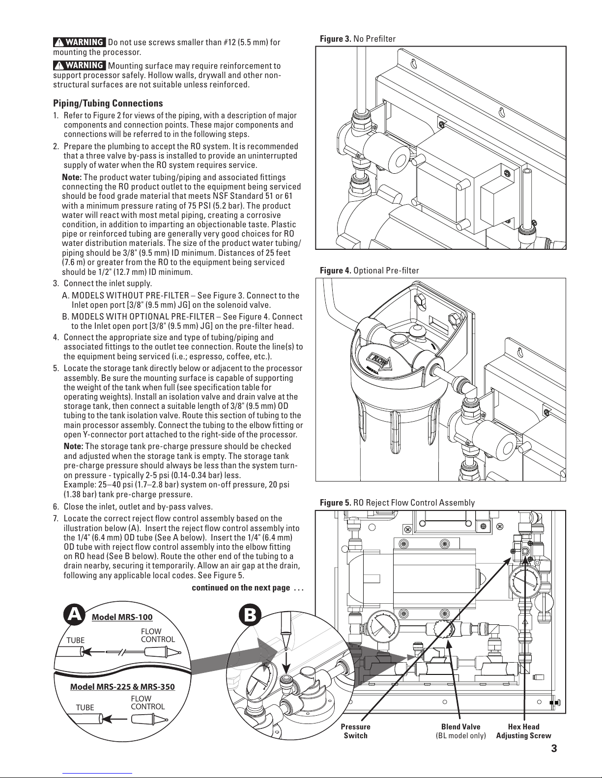
Figure 4. Optional Pre-filter
Figure 3. No Prefilter
Figure 5. RO Reject Flow Control Assembly
3
WARNING
Do not use screws smaller than #12 (5.5 mm) for
mounting the processor.
WARNING
Mounting surface may require reinforcement to
suppor t processor safely. Hollow walls, dry wall and other non-
structural surfaces are not suitable unless reinforced.
Piping/Tubing Connections
Refer to Figure 2 for views of the piping, with a description of major 1.
components and connection points. These major components and
connections will be referred to in the following steps.
Prepare the plumbing to accept the RO system. It is recommended2.
that a three valve by-pass is installed to provide an uninterrupted
supply of water when the RO system requires service.
Note: The product water tubing /piping and associated fittings
connecting the RO product outlet to the equipment being serviced
should be food grade material that meets NSF Standard 51 or 61
with a minimum pressure rating of 75 PSI (5.2 bar). The product
water will react with most metal piping, creating a corrosive
condition, in addition to imparting an objectionable taste. Plastic
pipe or reinforced tubing are generally very good choices for RO
water distribution materials. The size of the product water tubing/
piping should be 3/8" (9.5 mm) ID minimum. Distances of 25 feet
(7.6 m) or greater from the RO
to the equipment being serviced
should be 1/2" (12.7 mm) ID minimum.
Co3. nnect the inlet supply.
A. MODELS WITHOUT PRE-FILTER – See Figure 3. Connect to the
Inlet open port [3/ 8" (9.5 mm) JG] on the solenoid valve.
B. MODELS WITH OPTIONAL PRE-FILTER – See Figure 4. Connect
to the Inlet open port [3/8" (9.5 mm) JG] on the pre-filter head.
Connect the appropriate size and type of tubing/piping and 4.
associated fittings to the outlet tee connection. Route the line(s) to
the equipment being serviced (i.e.; espresso, cof fee, etc.).
Locate the storage tank directly below or adjacent to the processor 5.
assembly. Be sure the mounting surface is capable of supporting
the weight of the tank when full (see specification table for
operating weights). Install an isolation valve and drain valve at the
storage tank, then connect a suitable length of 3/8" (9.5 mm) OD
tubing to the tank isolation valve. Route this section of tubing to the
main processor assembly. Connect the tubing to the elbow fitting or
open Y-connector port attached to the right-side of the processor.
Note: The storage tank pre-charge pressure should be checked
and adjusted when the storage tank is empt y. The storage tank
pre-charge pressure should always be less than the system turn-
on pressure - typically 2-5 psi (0.14-0.34 bar) less.
Example: 25–40 psi (1.7–2.8 bar) system on-off pressure, 20 psi
(1.38 bar) tank pre-charge pressure.
Close the inlet, outlet and by-pass valves.6.
Locate the correct reject flow control assembly based on the 7.
illustration below (A). Insert the reject flow control assembly into
the 1/4" (6.4 mm) OD tube (See A below). Insert the 1/4" (6.4 mm)
OD tube with reject flow control assembly into the elbow fit ting
on RO head (See B below). Route the other end of the tubing to a
drain nearby, securing it temporarily. Allow an air gap at the drain,
following any applicable local codes. See Figure 5.
continued on the next page . . .
TUBE
FLOW
CONTROL
Model MRS-100
TUBE
FLOW
CONTROL
Model MRS-225 & MRS-350
Blend Valve
(BL model only)
Hex Head
Adjusting Screw
Pressure
Switch
 Loading...