

Everpure MRS-200 Installation And Startup Manual

Cat. No. EV311117
Rev. B 11/6/03
DCO #7060
MODEL MRS-200
Reverse Osmosis Mineral Reduction System
Installation and Start-up Guide
1

Table of Contents
Topic Page
Introduction……………………………………………………………... 3
System Installation…..…………………………………………………. 4
Cartridge Installation and Activation…..……………………………… 10
Start-Up and Blend Adjustment…..…….………...…………………… 10
Adjusting the Recovery…………..……………………………………. 12
Operation………………………………………………………....…….. 14
Maintenance……………………………………………………………. 14
Performance Monitoring………………………………………………. 16
TDS Measurement……………………………………………………… 16
Performance Log………………………………………………………. 17
Troubleshooting Guide………………………………………………… 18
Replacement Parts…………………………………………………….. 19
2

3
Introduction
The Everpure MRS-200 System is a pre-engineered, pre-assembled reverse osmosis system
designed to provide high purity water for many applications, such as premium espresso, coffee
and blended beverages, to name a few. It combines a number of water treatment technologies
into one easy to install package. The system provides superior protection against taste and odor
causing contaminants while removing dirt, particulates and dissolved solids that can foul or
scale equipment.
Please read this manual prior to installing and operating the system.
Initial Outlet Water Production
200 gal per day (52 Liters per day) @ 60 psig (340 kPa), 77o F (25o C)
Water production depends on supply water pressure and temperature.
TABLE 1 - Influent Water Characteristics
Pressure1 60-100 psig (414-690 kPa)
Temperature 33-100°F (1-38°C)
Total Dissolved Solids (TDS)2 0-2500 PPM (0-2500 mg/L)
pH 5-10
Chlorine3 0 PPM (0 mg/L)
Chloramine 0-3 PPM (0-3 mg/L)
Turbidity 0-10 NTU
Iron 0-1 PPM (0-1 mg/L)
1. For units with inlet pressure lower than 50 psig a booster pump is recommended.
2. Where TDS exceeds 600 PPM (600 mg/L) and the pressure less than 60 psig, a booster pump is recommended.
3. The reverse osmosis membrane filter used in this system will be damaged by chlorine. An activated carbon filter has
been provided with this system to protect the reverse osmosis membrane from chlorine attack. Influent chlorine
should not exceed 3 mg/L.
The MRS-200 System consists of seven major components:
1. Gallon/Calendar monitor.
2. 5-Micron Pre-filter.
3. Granular Activated Carbon Taste & Odor (TO) cartridge.
4. Reverse Osmosis (RO) membrane cartridge.
5. Filtered Water Blend Valve.
6. 15-gallon atmospheric Storage Tank.
7. Constant pressure product water Re-pressurization Pump.
The MRS-200 contains all the necessary piping, valves and fittings pre-assembled onto a floorstanding rack. Lengths of ¼” and 3/8” tubing are provided for connecting to the
wastewater/drain and sample/flushing lines.
The 5-micron pre-filter removes suspended particles, which can lead to pre-mature plugging of
the TO and/or RO membrane cartridge(s). The TO cartridge removes most oxidizers, but mainly
reduces chlorine, preventing damage to the RO cartridge. The RO cartridge contains a semipermeable reverse osmosis membrane. Here, most dissolved impurities are separated from the
water and flushed down the drain. The water that is able to pass through the membrane, which
is very low in dissolved impurities, enters the storage tank. This is referred to as RO water or
product water. In certain applications, some filtered water is mixed (via the filtered water blend
valve) with the product water to attain a specific level of total dissolved solids (TDS).

4
The storage tank stores water that has been produced by both the RO System and the filtered
water blend valve. It provides a water supply buffer enabling the system to provide reasonable
volumes of product water during high demand periods.
The product water re-pressurization pump develops and maintains the pressure required for
delivering the water from the storage tank to the connected equipment.
A unique cartridge monitor/alarm module has been included. This device can be set to provide
simultaneous water throughput and operating time indications over easily selectable ranges.
This monitor helps in determining cartridge change-out schedules.
Pre-Installation Checklist
1. ____ Can the unit be mounted within a reasonable distance of the water supply and
drain facilities?
2. ____ Are two 115 VAC GFIC protected receptacles available for connecting the 115
VAC/24 VAC transformer and product water re-pressurization pump?
3. ____ Is there adequate clearance and support to install the unit and permit access for
maintenance? The system will weigh approximately 175 pounds when the
storage tank is full.
4. ____ Does the inlet water supply meet the requirements listed below? 1
A minimum of 1.0 GPM at 50-100 psi pressure on a consistent basis
Less than 500 ppm Total Dissolved Solids
Less than 10 GPG of hardness
pH level between 7.0-9.0
Turbidity less than 1 NTU
1. Incoming water supplies that do not meet these requirements may need additional pre-treatment prior to the system.
System performance may be affected if requirements are not met, including system output production and cartridge
change-out frequency. Optional inlet booster pumps are available to increase supply water pressure and system
production.
System Installation
1. Locate the MRS-200 system in an area
that is convenient to the inlet water
supply and drain facilities, with access
for routing the product water
tubing/piping to the equipment. Also
consider ease of service when selecting
a location.
2. Refer to Figure 1 for assembling the four
legs to the shelf. Insert each leg fully
with the two half sleeves provided.
Adjust the leveling bolt(s) as required
until the shelf is stable and level in all
directions.
Figure 1
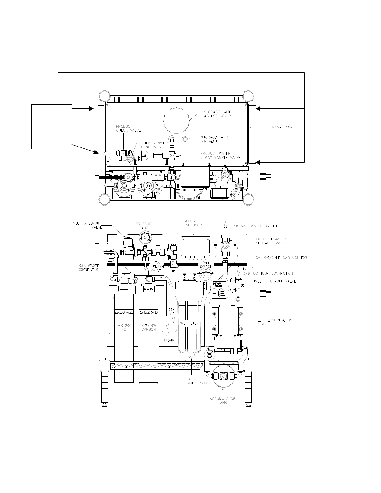
3. Refer to Figure 2 for a view of the complete assembly, with a description of major
components and connection points. Place the main unit on the shelf, positioning the
cartridge heads directly over the cutout area. Insert a cable tie into one of the holes in the
baseplate and through the wire “slats” in the shelf, making a secure loop. Do this with all
four corners of the baseplate.
Wire Tie
Baseplate
to RackFour (4)
Places.
Figure 2
5
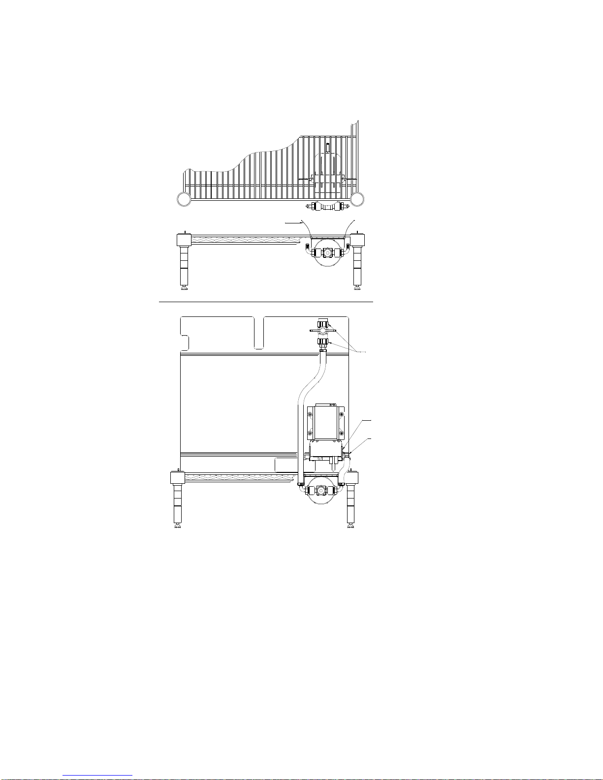
Refer to Figure 3 for information regarding the installation of the accumulator tank assembly.
Check/adjust the pre-charge to 40 PSI air pressure. Attach the accumulator tank to the rack
with the wire ties provided. Secure the elbow fitting to the pump discharge connection by
inserting fully and sliding the clip upward until it clicks. Attach the outlet valve to the clamps as
illustrated.
WIRE TIES
ATTACH TO BOTTOM SIDE OF RACK
WITH CABLE TIES ON 2ND RUNG & 8TH RUNG.
(HOSES REMOVED FOR CLARITY)
SNAP VALVE INTO
CLAMPS.
(COMPONENTS REMOVED FOR CLARITY)
1. SLIDE LOCKING CLIP
DOWN.
2. INSERT ELBOW FULLY.
3. SLIDE LOCKING CLIP
UP TO SECURE.
Figure 3
4. Water supplies with a dynamic operating pressure of 50 PSI or less require the use of the
booster pump to increase production. Water supplies with a dynamic operating pressure
greater than 50 PSI generally do not require the addition of a booster pump, unless certain
site specific conditions prevent the system from attaining the rated production output without
it. The booster pump increases the incoming pressure by approximately 45 PSI.
Do not install the inlet booster pump on water supplies with a dynamic pressure in
excess of 75 PSI.
Do not connect the MRS-200 system after any water filtration system, unless
specifically provided for use with the MRS-200.
6
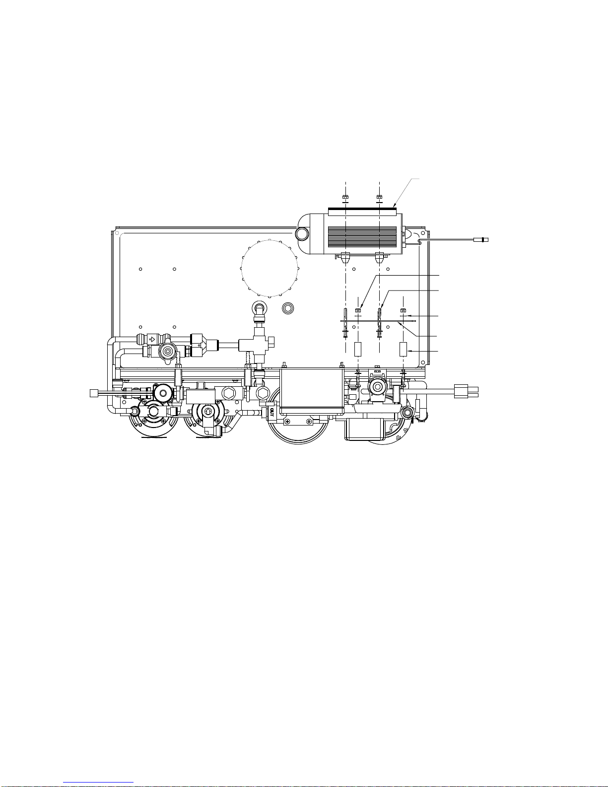
If a booster pump is required, refer to Figure 4. Assemble a male elbow fitting to the pump
inlet and a male connector fitting to the pump outlet. Attach the pump to the mounting plate
with the hardware provided. Attach the pump with mounting plate to the backplate with the
hardware provided. The flow arrows on the pump head should be pointing up to prevent air
entrapment. Attach a length of tubing from the pump outlet to the inlet shut-off valve.
BOOSTER
PUMP
#10 NUT (8)
#10 X 1-1/2" SCREW (8)
#10 WASHER (16)
MOUNTING PLATE
1/2Ø X 1"
SPACER (4)
Figure 4
5. Refer to Figure 5 for a sample general arrangement. Use this as a guideline for determining
valve location, tubing/pipe sizes, etc.
Note: This is only a guideline and your installation may include fewer or greater number of
components than outlined.
6. The cartridge usage monitor requires two AAA batteries. Do not install the batteries until
installation is completed and the system is ready to put into service.
7. Connect the water to be treated to the system inlet shut-off valve on systems without a
booster pump or to the booster pump inlet on models with a booster pump.
7
 Loading...