

Page 1

EVERLIGHT ELECTRONICS CO.,LTD.
Technical Data Sheet
Infrared Remote-Control Receiver Module
Features :
• Photo detector and preamplifier in one package
• Internal filter for PCM frequency
• Improved shielding against electrical field disturbance
• TTL and CMOS compatibility
• Output active low
• Low power consumption
• Improved immunity against ambient light
• Suitable min. burst length≧6 or 10 pulses/burst.
• The product itself will remain within RoHS compliant version.
• Pb free
IRM-3738S18
Descriptions
‧The device is a miniature type infrared remote control system
receiver which has been developed and designed by utilizing the
most updated IC technology. The PIN diode and preamplifier are
assembled on lead frame, the epoxy package is designed as an IR
filter. The demodulated output signal can directly be decoded by a
microprocessor.
Applications
1. Optical switch
2. Light detecting portion of remote control
․AV instruments such as Audio, TV, VCR, CD, MD, etc.
․Home appliances such as Air-conditioner, Fan , etc.
․The other equipments with wireless remote control.
․CATV set top boxes
․Multi-media Equipment
PART MATERIAL COLOR
Chip Silicon Black
Shell Epoxy Silver-white
Everlight Electronics Co., Ltd. http:\\www.everlight.com Rev 2 Page: 1 of 9
Device No:SZDMO-037-004 Prepared date:07-28-2005 Prepared by:Hao Liu
Page 2
EVERLIGHT ELECTRONICS CO.,LTD.
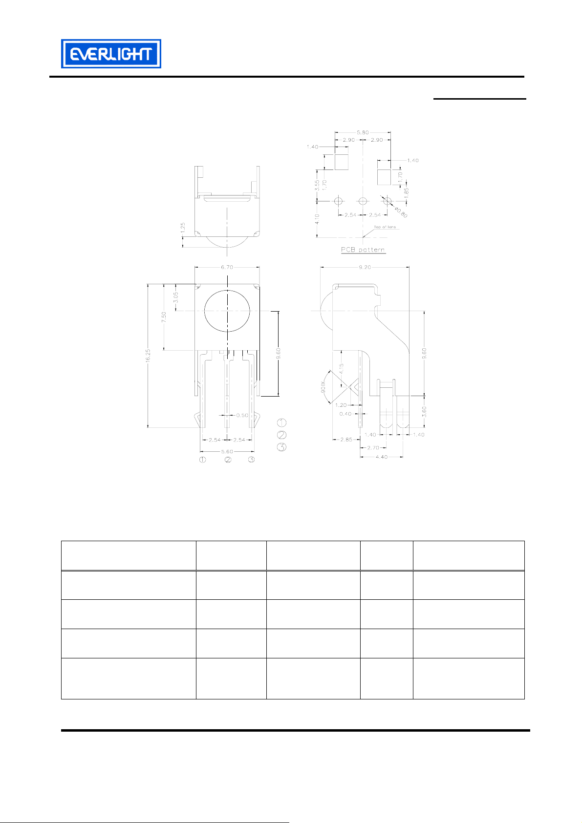
Package Dimensions
IRM-3738S18
Notes: 1.All dimensions are in millimeters.
2.Tolerances unless dimensions ±0.3mm.
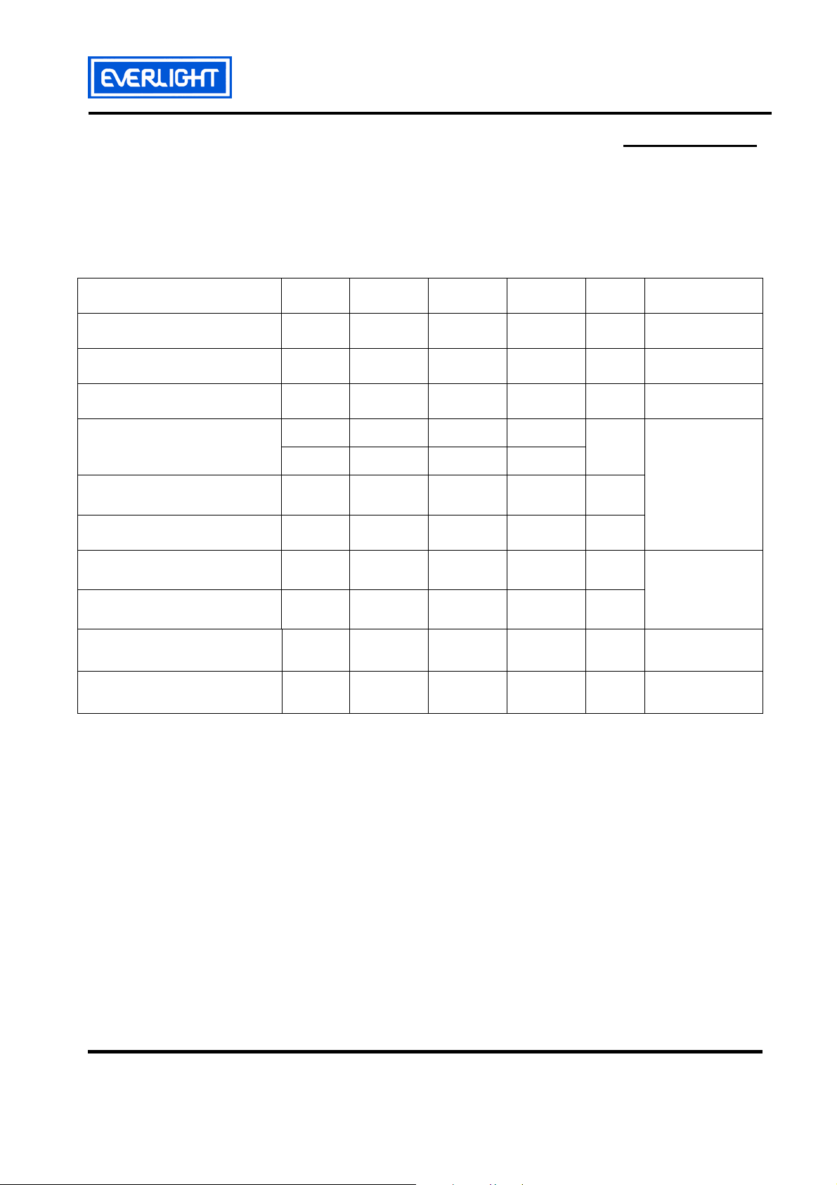
Absolute Maximum Ratings (Ta=25℃)
Parameter Symbol Rating Unit
Supply Voltage Vcc
Operating Temperature Topr
Storage Temperature Tstg
Soldering Temperature Tsol
OUT
Vcc
GND
0~6
-25 ~ +85
-25 ~ +85
260
Notice
V
℃
℃
℃
4mm from mold body
less than 10 seconds
Everlight Electronics Co., Ltd. http:\\www.everlight.com Rev 2 Page: 2 of 9
Device No:SZDMO-037-004 Prepared date:07-28-2005 Prepared by:Hao Liu
Page 3
EVERLIGHT ELECTRONICS CO.,LTD.
Recommended Operating Condition
Supply Voltage Rating: Vcc 2.7V to 5.5V
Electro-Optical Characteristics (Ta=25℃, and Vcc=3.0V)
IRM-3738S18
Parameter Symbol MIN. TYP. MAX. Unit
Consumption Current Icc
B.P.F Center Frequency Fo
Peak Wavelength
Reception Distance
Half Angle(Horizontal)
Half Angle(Vertical)
High Level Pulse Width TH
Low Level Pulse Width TL
High Level Output Voltage VH
Low Level Output Voltage VL
λ
L0
L45
Θ
Θ
Condition
0.7 0.9 1.2
--- 38 ---
p
h
v
--- 940 --8 --- ---
5 --- ---
--- 45 ---
--- 45 ---
400 --- 800
400 --- 800
2.5 --- --- V
--- 0.2 0.5 V
mA No signal input
KHz
nm
m
deg
deg
μs
μs
At the ray axis
*1
At the ray axis
*2
*1:The ray receiving surface at a vertex and relation to the ray axis in the range of θ= 0° and θ=45°.
*2:A range from 30cm to the arrival distance. Average value of 50 pulses.
Everlight Electronics Co., Ltd. http:\\www.everlight.com Rev 2 Page: 3 of 9
Device No:SZDMO-037-004 Prepared date:07-28-2005 Prepared by:Hao Liu
Page 4

EVERLIGHT ELECTRONICS CO.,LTD.
IRM-3738S18
Test Method:
The specified electro-optical characteristics is satisfied under the following
Conditions at the controllable distance.
cMeasurement place
A place that is nothing of extreme light reflected in the room.
dExternal light
Project the light of ordinary white fluorescent lamps which are not high
Frequency lamps and must be less then 10 Lux at the module surface.
(Ee≦10Lux)
eStandard transmitter
A transmitter whose output is so adjusted as to Vo=400mVp-p and the output
Wave form shown in Fig.-1.According to the measurement method shown in
Fig.-2 the standard transmitter is specified.
However , the infrared photodiode to be used for the transmitter should be
λp=940nm,∆λ=50nm. Also, photodiode is used of PD438B(Vr=5V).
fMeasuring system
According to the measuring system shown in Fig.-3
Fig.-1 Transmitter Wave Form D.U.T output Pulse
IR TANSMITTER
OUTPUT WAVE FORM
Carrier frequency is adjusted to
center frequency of each product.
Duty=0.5
OUTPUT PULSE
OF DEVICE
Everlight Electronics Co., Ltd. http:\\www.everlight.com Rev 2 Page: 4 of 9
Device No:SZDMO-037-004 Prepared date:07-28-2005 Prepared by:Hao Liu
Page 5

EVERLIGHT ELECTRONICS CO.,LTD.
r
r
µ
IRM-3738S18
Fig.-2 Measuring Method Fig.-3 Measuring System
Standard Transmitter
Block Diagram:
20cm
10k
+5.0± 0.1V
10uF
k
0
0
1
Oscilloscope
Vout
Standard Transmitter
Vs
L: Transmission Distance
θ
θ
D.U.T
θ: Angle Of Horizontal & Vertical Direction
OUT
GND
Vcc
Vout
Input CGA & filte
Demodulato
Oscillator AGC/ATC & digital control
Carrier frequency f0
Modulated IR signal
min 6/10 pulses
GND
Application Circuit:
RC Filter should be connected closely between Vcc pin and GND pin.
OUTIN
C
Everlight Electronics Co., Ltd. http:\\www.everlight.com Rev 2 Page: 5 of 9
Device No:SZDMO-037-004 Prepared date:07-28-2005 Prepared by:Hao Liu
Page 6

EVERLIGHT ELECTRONICS CO.,LTD.
Typical Electro-Optical Characteristics Curves
IRM-3738S18
Fig.-4 Relative Spectral Sensitivity vs.
Wavelength
Fig.-5 Relative Transmission Distance vs.
Direction
θ
Fig.-6 Output Pulse Length vs. Arrival Distance Fig.-7 Arrival Distance vs. Supply Voltage
17.5
10.5
7.0
3.5
Transmission Distance Lc (m)
4.4
3.32.703.0
3.83.5 4.1 5.0
Supply Voltage Vcc (V)
4.7
5.3
5.5
Everlight Electronics Co., Ltd. http:\\www.everlight.com Rev 2 Page: 6 of 9
Device No:SZDMO-037-004 Prepared date:07-28-2005 Prepared by:Hao Liu
Page 7

EVERLIGHT ELECTRONICS CO.,LTD.
IRM-3738S18
Typical Electro-Optical Characteristics Curves
Fig.-8 Relative Transmission Distance
vs. Center Carrier Frequency
Fig.-9 Arrival Distance vs. Ambient Temperature
Everlight Electronics Co., Ltd. http:\\www.everlight.com Rev 2 Page: 7 of 9
Device No:SZDMO-037-004 Prepared date:07-28-2005 Prepared by:Hao Liu
Page 8

EVERLIGHT ELECTRONICS CO.,LTD.
Reliability Test Item And Condition
The reliability of products shall be satisfied with items listed below.
Confidence level:90%
LTPD:10%
IRM-3738S18
Test Items Test Conditions
Temperature cycle
High temperature test
Low temperature
storage
High temperature
High humidity
Solder heat
1 cycle -25℃ +85℃
(30min)(5min)(30min)
300 cycle test
Temp: +85℃
Vcc:5V
1000hrs
Temp: -25℃
1000hrs
Ta: 85℃,RH:85%
1000hrs
Temp: 260±5℃ 10sec
4mm From the bottom of the package.
Failure Judgement
Criteria
L0≦ L×0.8
L45≦ L×0.8
L: Lower
specification limit
Samples(n)
Defective(c)
n=22,c=0
n=22,c=0
n=22,c=0
n=22,c=0
n=22,c=0
Everlight Electronics Co., Ltd. http:\\www.everlight.com Rev 2 Page: 8 of 9
Device No:SZDMO-037-004 Prepared date:07-28-2005 Prepared by:Hao Liu
Page 9
EVERLIGHT ELECTRONICS CO.,LTD.
Packing Quantity Specification
1. 1000PCS/1Box
2. 10Boxes/1Carton
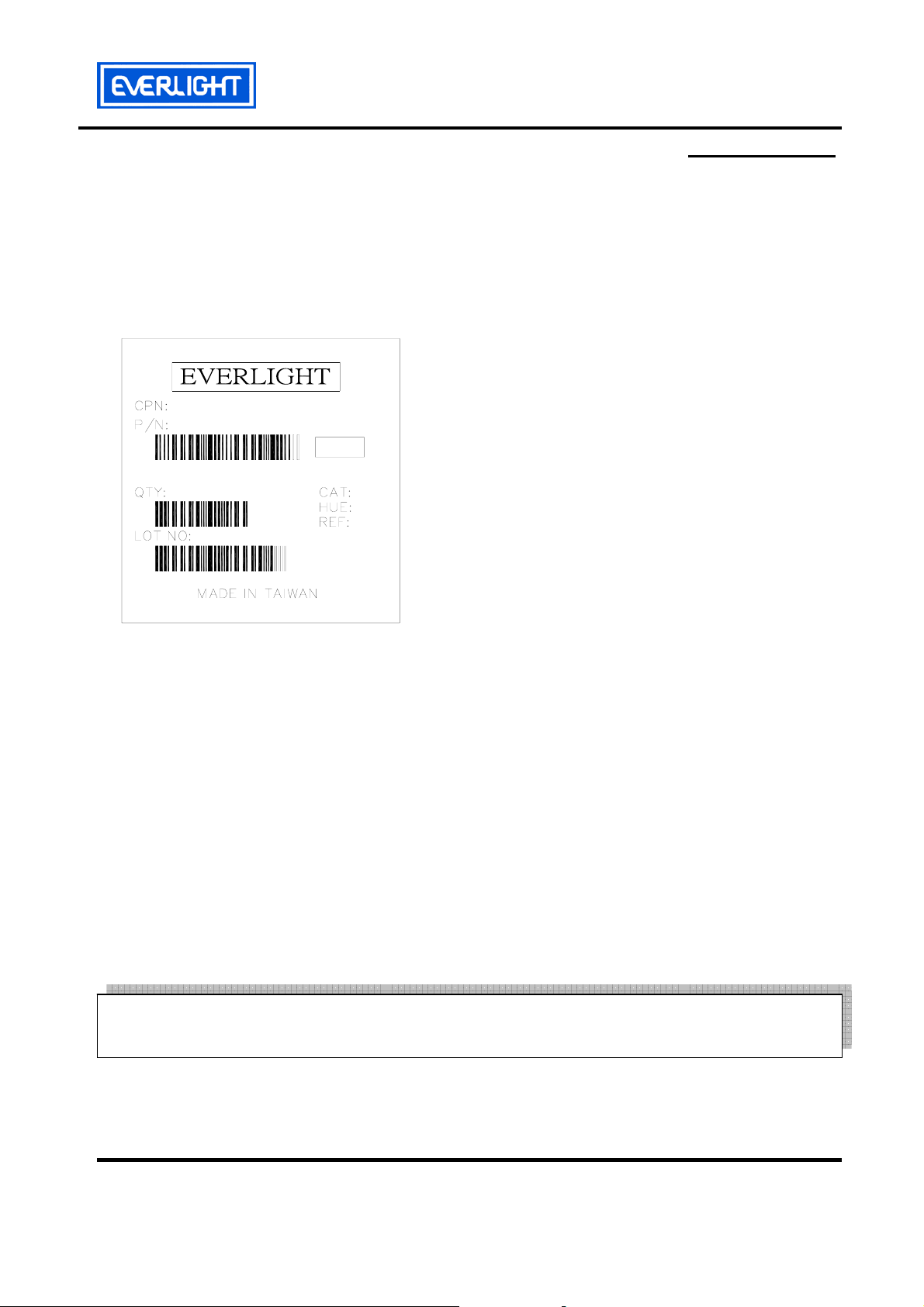
Label Form Specification
RoHS
IRM-3738S18
IRM-3738S18
CPN: Customer’s Production Number
P/N : Production Number
QTY: Packing Quantity
CAT: Ranks
HUE: Peak Wavelength
REF: Reference
LOT No: Lot Number
MADE IN TAIWAN: Production Place
Notes
1. Above specification may be changed without notice. EVERLIGHT will reserve authority on
material change for above specification.
2. When using this product, please observe the absolute maximum ratings and the instructions
for using outlined in these specification sheets. EVERLIGHT assumes no responsibility for
any damage resulting from use of the product which does not comply with the absolute
maximum ratings and the instructions included in these specification sheets.
3. These specification sheets include materials protected under copyright of EVERLIGHT
corporation. Please don’t reproduce or cause anyone to reproduce them without
EVERLIGHT’s consent.
EVERLIGHT ELECTRONICS CO., LTD. Tel: 886-2-2267-2000, 2267-9936
Office: No 25, Lane 76, Sec 3, Chung Yang Rd, Fax: 886-2267-6244, 2267-6189, 2267-6306
Tucheng, Taipei 236, Taiwan, R.O.C http:\\www.everlight.com
Everlight Electronics Co., Ltd. http:\\www.everlight.com Rev 2 Page: 9 of 9
Device No:SZDMO-037-004 Prepared date:07-28-2005 Prepared by:Hao Liu
 Loading...