

Page 1
EVERLIGHT ELECTRONICS CO.,LTD.
Technical Data Sheet
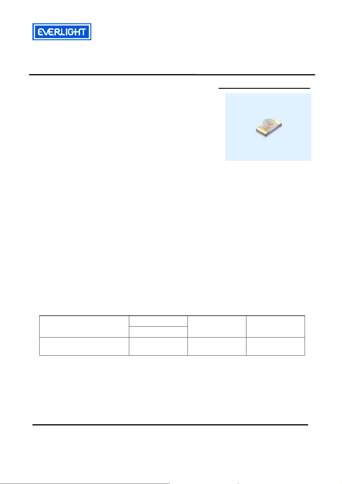
Reverse Package Chip LED with Inner Lens
Features
․Package in 8mm tape on 7〞diameter reel.
․Compatible with automatic placement equipment.
․Compatible with infrared and vapor phase reflow
solder process.
․Mono-color type.
․Pb-free.
․The product itself will remain within RoHS compliant version.
Descriptions
․The 25-21 SMD LED is much smaller than lead
frame type components, thus enable smaller
board size, higher packing density, reduced
storage space and finally smaller equipment to be
obtained.
․Besides, lightweight makes them ideal for
miniature applications. etc.
Applications
․Backlighting in dashboard and switch.
․Telecommunication: indicator and backlighting in
telephone and fax.
․Flat backlight for LCD, switch and symbol.
․General use.
25-21/T1D-APQHY/2A
Device Selection Guide
Part No.
25-21/T1D-APQHY/2A
Everlight Electronics Co., Ltd. http://www.everlight.com Rev. 1 Page: 1 of 11
Device No.: SZDSE-251-T02 Prepared date:24-Jan-2008 Prepared by:Qilong Chen
Chip
Material
InGaN
Emitted Color Resin Color
Pure White Yellow Diffused
Page 2
EVERLIGHT ELECTRONICS CO.,LTD.
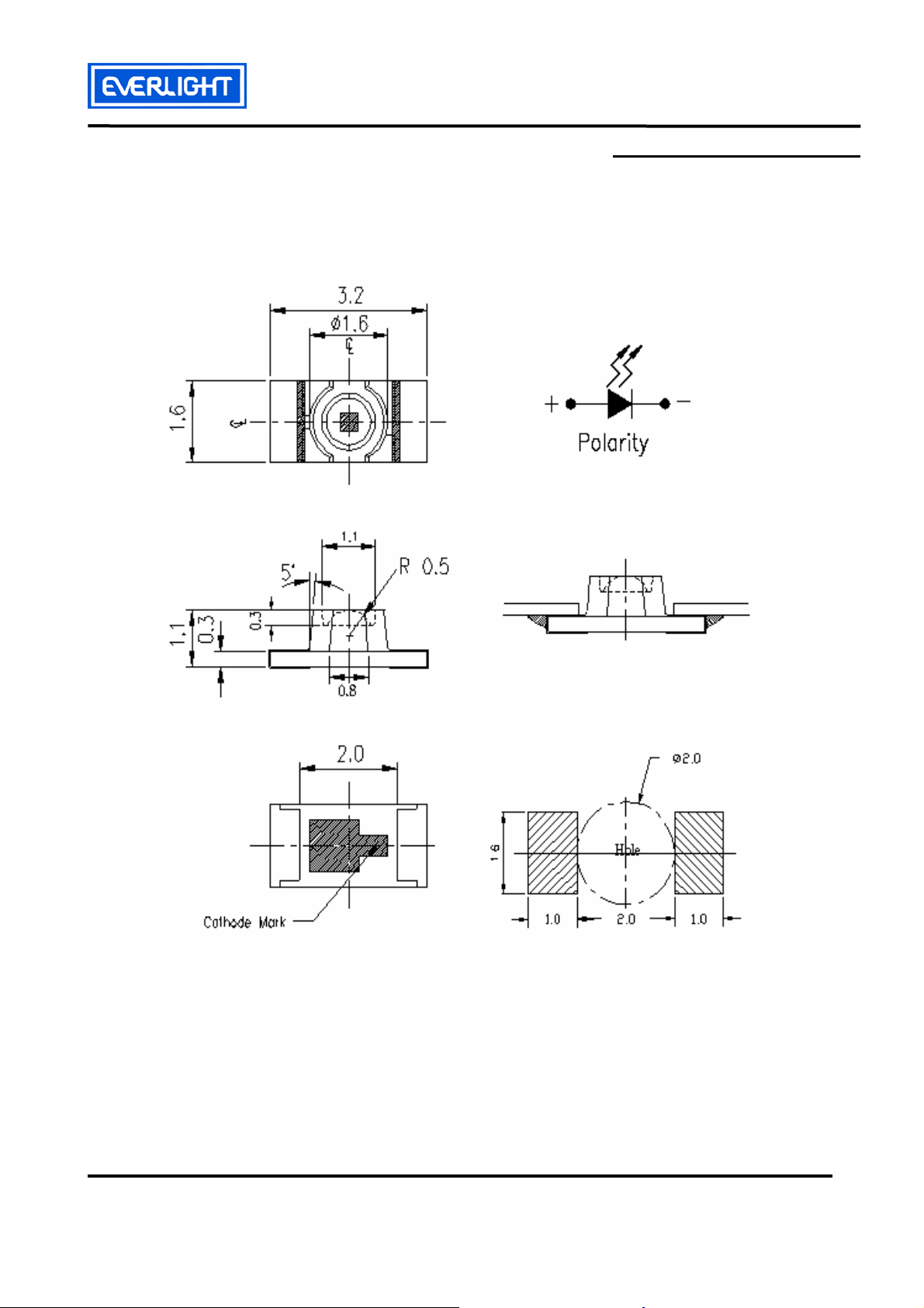
Package Outline Dimensions
25-21/T1D-APQHY/2A
Note: The tolerances unless mentioned is ±0.1mm , Angle±0.5°,Unit = mm
Everlight Electronics Co., Ltd. http://www.everlight.com Rev. 1 Page: 2 of 11
Device No.: SZDSE-251-T02 Prepared date:24-Jan-2008 Prepared by: Qilong Chen
Page 3
EVERLIGHT ELECTRONICS CO.,LTD.
25-21/T1D-APQHY/2A
Absolute Maximum Ratings (Ta=25℃)
Parameter Symbol Rating Unit
Reverse Voltage V
Forward Current I
R
F
Peak Forward Current
I
(Duty 1/10 @1KHz)
Power Dissipation P
FP
d
Electrostatic Discharge(HBM) ESD 150 V
Operating Temperature Topr -40 ~ +85 ℃
Storage Temperature Tstg -40 ~ +90 ℃
Soldering Temperature Tsol
Electro-Optical Characteristics (Ta=25℃)
Parameter Symbol Min. Typ. Max. Unit Condition
5 V
25 mA
100 mA
95 mW
Reflow Soldering : 260 ℃ for 10 sec.
Hand Soldering : 350 ℃ for 3 sec.
Luminous Intensity I
Viewing Angle 2θ
Forward Voltage V
Reverse Current I
v
1/2
F 2.7 ----- 3.15
R
45.0 ---- 112.0 mcd
----- 70 ----- deg
----- ----- 50 μA
Bin Range Of Luminous Intensity & Forward Voltage
Symbol Bin Code Min. Max. Unit Condition
P 45.0 72.0
Q 72.0 112
15 2.70 2.85
V
F
16 2.85 3.00
17 3.00 3.15
Notes:
1.Tolerance of Luminous Intensity ±15%
IF=20 mA
V
VR=5V
mcd IF=5mA
V I
=5mA
F
2.Tolerance of Forward Voltage ±0.1V
Everlight Electronics Co., Ltd. http://www.everlight.com Rev. 1 Page: 3 of 11
Device No.: SZDSE-251-T02 Prepared date:24-Jan-2008 Prepared by: Qilong Chen
Page 4
EVERLIGHT ELECTRONICS CO.,LTD.
25-21/T1D-APQHY/2A
Chromaticity Coordinates Specifications for Bin Grading
Groups Bin Code CIE_x CIE_y Condition
0.274 0.226
A
1
0.274 0.258
0.294 0.286
0.294 0.254
0.274 0.258
0.274 0.291
2
0.294 0.319
0.294 0.286
0.294 0.254
0.294 0.286
3
0.314 0.315
0.314 0.282
IF=5mA
0.294 0.286
0.294 0.319
4
0.314 0.347
0.314 0.315
0.314 0.282
5
6
0.314 0.315
0.334 0.343
0.334 0.311
0.314 0.315
0.314 0.347
0.334 0.376
0.334 0.343
Notes:
1.The C.I.E. 1931 chromaticity diagram ( Tolerance ±0.01).
2.The products are sensitive to static electricity and care must be fully taken when
handling products.
Everlight Electronics Co., Ltd. http://www.everlight.com Rev. 1 Page: 4 of 11
Device No.: SZDSE-251-T02 Prepared date:24-Jan-2008 Prepared by: Qilong Chen
Page 5

EVERLIGHT ELECTRONICS CO.,LTD.
25-21/T1D-APQHY/2A
CIE Chromaticity Diagram
Everlight Electronics Co., Ltd. http://www.everlight.com Rev. 1 Page: 5 of 11
Device No.: SZDSE-251-T02 Prepared date:24-Jan-2008 Prepared by: Qilong Chen
Page 6

EVERLIGHT ELECTRONICS CO.,LTD.
Typical Electro-Optical Characteristics Curves
25-21/T1D-APQHY/2A
Everlight Electronics Co., Ltd. http://www.everlight.com Rev. 1 Page: 6 of 11
Device No.: SZDSE-251-T02 Prepared date:24-Jan-2008 Prepared by: Qilong Chen
Page 7

EVERLIGHT ELECTRONICS CO.,LTD.
25-21/T1D-APQHY/2A
Label explanation
CAT: Luminous Intensity (mcd) HUE: Chromaticity Coordinates REF: Forward Voltage (V)
RoHS
Reel Dimensions
Note: The tolerances unless mentioned is ±0.1mm ,Unit = mm
Everlight Electronics Co., Ltd. http://www.everlight.com Rev. 1 Page: 7 of 11
Device No.: SZDSE-251-T02 Prepared date:24-Jan-2008 Prepared by: Qilong Chen
Page 8

EVERLIGHT ELECTRONICS CO.,LTD.
25-21/T1D-APQHY/2A
Carrier Tape Dimensions : Loaded quantity 2000 pcs per reel
Note: The tolerances unless mentioned is ±0.1mm ,Unit = mm
Moisture Resistant Packaging
Label
Aluminum moisture-proof bag
Desiccant Label
Everlight Electronics Co., Ltd. http://www.everlight.com Rev. 1 Page: 8 of 11
Device No.: SZDSE-251-T02 Prepared date:24-Jan-2008 Prepared by: Qilong Chen
Page 9

EVERLIGHT ELECTRONICS CO.,LTD.
25-21/T1D-APQHY/2A
Reliability Test Items And Conditions
The reliability of products shall be satisfied with items listed below.
Confidence level : 90 %
LTPD : 10 %
No. Items Test Condition
Test
Hours/Cycles
Temp. : 260℃±5℃
1 Reflow Soldering
Min. 5sec.
6 Min.
H : +100℃ 15min
2 Temperature Cycle
∫ 5 min
300 Cycles
L : -40℃ 15min
H : +100℃ 5min
3 Thermal Shock
∫ 10 sec
300 Cycles
L : -10℃ 5min
4
High Temperature
Temp. : 100℃
1000 Hrs.
Storage
5
Low Temperature
Temp. : -40℃
1000 Hrs.
Storage
6 DC Operating Life IF = 20 mA
1000 Hrs.
Sample
Ac/Re
Size
22 PCS. 0/1
22 PCS. 0/1
22 PCS. 0/1
22 PCS. 0/1
22 PCS. 0/1
22 PCS. 0/1
7
High Temperature /
85℃/ 85%RH
1000 Hrs.
22 PCS. 0/1
High Humidity
Everlight Electronics Co., Ltd. http://www.everlight.com Rev. 1 Page: 9 of 11
Device No.: SZDSE-251-T02 Prepared date:24-Jan-2008 Prepared by: Qilong Chen
Page 10

EVERLIGHT ELECTRONICS CO.,LTD.
25-21/T1D-APQHY/2A
Precautions For Use
1. Over-current-proof
Customer must apply resistors for protection , otherwise slight voltage shift will cause big
current change ( Burn out will happen ).
2. Storage
2.1 Do not open moisture proof bag before the products are ready to use.
2.2 Before opening the package: The LEDs should be kept at 30℃ or less and 90%RH or less.
2.3 After opening the package: The LED's floor life is 1 year under 30℃ or less and 60% RH or less.
If unused LEDs remain, it should be stored in moisture proof packages.
2.4 If the moisture absorbent material (silica gel) has faded away or the LEDs have exceeded the
storage time, baking treatment should be performed using the following conditions.
Baking treatment : 60±5℃ for 24 hours.
3. Soldering Condition
3.1 Pb-free solder temperature profile
3.2 Reflow soldering should not be done more than two times.
3.3 When soldering, do not put stress on the LEDs during heating.
3.4 After soldering, do not warp the circuit board.
4. Soldering Iron
Each terminal is to go to the tip of soldering iron temperature less than 350℃ for 3 seconds
within once in less than the soldering iron capacity 25W. Leave two seconds and more intervals, and do
soldering of each terminal. Be careful because the damage of the product is often started at the time of
the hand solder.
Everlight Electronics Co., Ltd. http://www.everlight.com Rev. 1 Page: 10 of 11
Device No.: SZDSE-251-T02 Prepared date:24-Jan-2008 Prepared by: Qilong Chen
Page 11
EVERLIGHT ELECTRONICS CO.,LTD.
25-21/T1D-APQHY/2A
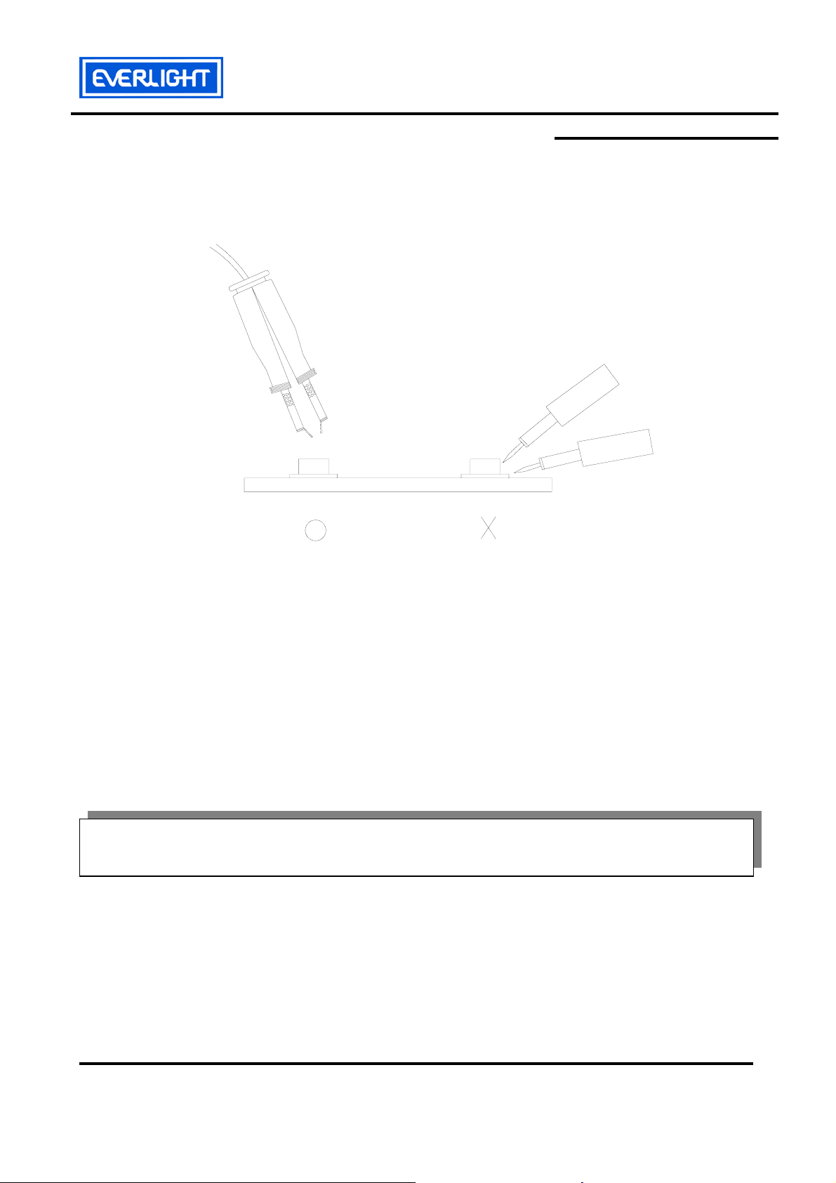
5.Repairing
Repair should not be done after the LEDs have been soldered. When repairing is unavoidable,
a double-head soldering iron should be used (as below figure). It should be confirmed beforehand
whether the characteristics of the LEDs will or will not be damaged by repairing.
EVERLIGHT ELECTRONICS CO., LTD. Tel: 886-2-2267-2000, 2267-9936
Office: No 25, Lane 76, Sec 3, Chung Yang Rd, Fax: 886-2267-6244, 2267-6189, 2267-6306
Tucheng, Taipei 236, Taiwan, R.O.C http://www.everlight.com
Everlight Electronics Co., Ltd. http://www.everlight.com Rev. 1 Page: 11 of 11
Device No.: SZDSE-251-T02 Prepared date:24-Jan-2008 Prepared by: Qilong Chen
 Loading...