

EverFocus EZN Plus Series, EZN3160 Plus, EZN3260 Plus, EZN3340 Plus User Manual

EZN Plus Series
Outdoor IR Bullet IP Camera
User’s Manual
Copyright © EverFocus Electronics Corp,
Release Date: October, 2012

Copyright 2012 EverFocus Electronics Corp.
All rights reserved. No part of the contents of this manual may be reproduced or transmitted in any form or by
any means without written permission of the EverFocus Electronics Corporation.
EverFocus
12F, No.79, Sec. 1, Shin-Tai Wu Road,
Hsi-Chih, Taipei, Taiwan
TEL: +886 2 2698 2334
FAX: +886 2 2698 2380
www.everfocus.com.tw
October, 2012

i
Regulatory Notices
About this document
All the safety and operating instructions should be read and followed before the unit is operated. This
manual should be retained for future reference. The information in this manual was current when
published. The manufacturer reserves the right to revise and improve its products. All specifications are
therefore subject to change without notice.
FCC Notice "Declaration of Conformity Information"
This equipment has been tested and found to comply with the limits for a Class
A digital device, pursuant to part 15 of the FCC Rules. These limits are designed to provide reasonable
protection against harmful interference in a residential installation. This equipment generates, uses and
can radiate radio frequency energy and, if not installed and used in accordance with the instructions,
may cause harmful interference to radio communications. However, there is no guarantee that
interference will not occur in a particular installation. If this equipment does cause harmful interference
to radio or television reception, which can be determined by turning the equipment off and on, the user
is encouraged to try to correct the interference by one or more of the following measures:
- Reorient or relocate the receiving antenna.
- Increase the separation between the equipment and receiver.
- Connect the equipment into an outlet on a circuit different from that to which the receiver is
connected.
- Consult the dealer or an experienced radio/TV technician for help.
Warning: Changes or modifications made to this equipment, not expressly approved by EverFocus or
parties authorized by EverFocus could void the user's authority to operate the equipment.
This device complies with part 15 of the FCC Rules. Operation is subject to the following two conditions:
(1) This device may not cause harmful interference, and
(2) This device must accept any interference received, including interference that may cause undesired
operation.
EverFocus Electronics Corp.
12F, No. 79, Sec. 1, Shin-Tai Wu Rd., Hsi-Chi,
Taipei Hsien, Taiwan, R.O.C.
EZN Plus Series cameras comply with CE and FCC.

ii
Safety Notice
-These limits are designed to provide reasonable protection. This equipment generates, uses and can
radiated radio frequency energy and, if not installed and used in accordance with the instructions, may
cause harmful interference to radio communications. However, there is no guarantee that interference
will not occur in a particular installation. If this equipment does cause harmful interference to radio or
television reception, which can be determined by turning the equipment off and on, the user is
encouraged to try to correct the interference by one or more of the following measures: -Reorient or
relocate the receiving antenna.
-Increase these separations between the equipment and receiver.
-Connect the equipment into an outlet on a circuit different from that to which the receiver is connected.
-Consult the dealer or an experienced radio/TV technician for help.
The changes or modifications not expressly approved by the party responsible for compliance could void
the user's authority to operate the equipment.
To reduce risk of fire or electric shock, do not expose this appliance to rain or moisture.
Do not attempt to disassemble the appliance. To prevent electric shock, do not remove screws or
covers. There are no user-serviceable parts inside. Contact qualified service personnel for maintenance.
Handle the appliance with care. Do not strike or shake, as this may damage the appliance.
Do not use strong or abrasive detergents when cleaning the appliance body. Use a dry cloth to
clean the appliance when it is dirty. When the dirt is hard to remove, use a mild detergent and wipe
gently.
Do not operate the appliance beyond its specified temperature, humidity or power source ratings.
The input power source for this appliance is DC 12V & PoE. Do not use the appliance in an extreme
environment where high temperature or high humidity exists. Use the appliance at a temperature
between -40°C ~ 55°C / -40°F ~ 131°F (DC 12V); -20°C ~ 55°C / -4°F ~ 131°F (PoE) and humidity between
20% ~ 80%.

iii
Use only the recommended power supplies. Power supplies must comply with the requirement of
the latest version of IEC60950-1. Substitutions may damage the unit or cause a fire or shock hazard.
Electrostatic-sensitive device. Use proper CMOS/MOSFET handing precautions to avoid
electrostatic discharge.
Installation should be performed by qualified service personnel only in accordance with the
National Electrical Code or applicable local codes.
Terms and Trademark
Ethernet, Internet Explorer, Linux, Microsoft, Windows, WWW are registered trademarks of the
respective holders. Other product names appearing in this User's Guide may be trademarks or registered
trademarks of their respective holders. Java™ and all Java-related logos and trademarks are trademarks
or registered trademarks of Sun Microsystems, Inc. in the United States and other countries.
Support
If the unit ever needs to be repaired or serviced, the customer should contact the nearest EverFocus
Electronics Corp. Service Center for return authorization and shipping instructions.

iv
TABLE OF CONTENTS
1. Introduction ..................................................................................................................................... 1
2. Features ........................................................................................................................................... 2
3. Overview ......................................................................................................................................... 3
4. Installation ....................................................................................................................................... 4
4.1 Packing List ................................................................................................................................. 4
4.2 4-Pin Data Cable ....................................................................................................................... 4
4.3 Basic Installation ............................................................................................................................ 5
4.3.1 Mounting and Wiring ................................................................................................ 5
4.3.2 Inserting a Micro SD Card ....................................................................................... 7
4.3.3 Adjusting Camera Focus / Zoom ............................................................................ 8
5. Accessing the User Interface ............................................................................................................. 9
5.1 Assigning an IP Address ................................................................................................................. 9
5.2 Settings for Microsoft Internet Explorer ...................................................................................... 11
5.3 Connecting the Camera to the Network ...................................................................................... 13
5.4 Live View Window ........................................................................................................................ 15
6. Playback ......................................................................................................................................... 19
6.1 Assigning an IP Address ............................................................................................................... 19
6.2 Setting Up the Playback Function ................................................................................................ 21
6.2.1 Preparing the Micro SD Card ................................................................................ 21
6.2.2 Testing the Playback Function ............................................................................. 22
6.3 Playing Back Using ARV Viewer ................................................................................................... 23
7. Settings .......................................................................................................................................... 24
7.1 System Info .................................................................................................................................. 24
7.1.1 Information .................................................................................... 24
7.1.2 Log ................................................................................................ 25
7.2 User Config ................................................................................................................................... 26
7.2.1 Live View Config ............................................................................. 26
7.2.2 Recording / Snapshot ...................................................................... 27
7.2.3 Language ....................................................................................... 28

v
7.3 Network ....................................................................................................................................... 29
7.3.1 Network ......................................................................................... 29
7.3.2 DDNS ............................................................................................. 31
7.3.3 SMTP / FTP ..................................................................................... 33
7.3.4 HTTPS ............................................................................................ 35
7.3.5 SNMP ............................................................................................. 38
7.3.6 Network Alarm ............................................................................... 38
7.4 Video ............................................................................................................................................ 39
7.4.1 Multi Streaming .............................................................................. 39
7.4.2 Camera .......................................................................................... 41
7.4.3 Advanced ....................................................................................... 43
7.4.4 ROI (Region of Interest) .................................................................. 49
7.4.5 Privacy Mask .................................................................................. 50
7.5 Audio ............................................................................................................................................ 52
7.6 User .............................................................................................................................................. 53
7.6.1 User Information ............................................................................ 53
7.6.2 IP Address Filter ............................................................................. 55
7.7 Event ............................................................................................................................................ 56
7.7.1 Event Settings ................................................................................ 56
7.7.2 Motion Detection ........................................................................... 59
7.7.3 Tamper Detection ........................................................................... 60
7.7.4 Alarm I/O ....................................................................................... 60
7.7.5 Schedule ........................................................................................ 61
7.8 System .......................................................................................................................................... 62
7.8.1 Date/Time ...................................................................................... 62
7.8.2 Daylight Saving ............................................................................... 63
7.8.3 SD Card .......................................................................................... 63
7.8.4 Maintenance .................................................................................. 64
8. Upgrading Firmware Using IP Utility ............................................................................................... 66
9. Specifications ................................................................................................................................. 68
EZNPlusSeries
1
1. Introduction
TheEZNPlusseriesisanoutdoorbulletcameradeliveringimagequalityofupto3‐megapixel.Thecamera
supportsbothH.264andMJPEGcompressionformats.TheIP66‐ratingandvandalproofhousingmakeit
suitableforoutdooruse.TheIRLEDsarealsoimplementedforinfraredilluminationinnightvision
applications.
TheEZNPlusseriesfeaturestheWideDynamicRange(WDR)function,whichcanprovideclearimages
evenunderbacklightcircumstanceswhereintensityofilluminationcanvaryexcessively.Abuilt‐inmicro
SDHCcardslotandPoweroverEthernet(IEEE802.3af)featuresarealsoprovided.Youcanpowerthe
cameraoverthenetworkorbyconnectingthecameratoa12VDCpowersupply.SincetheEZNPlusseries
conformstoONVIF/PSIAforcompatibilitywithothernetworkvideodevices,itinteroperateswithawide
varietyofhardwareandsoftwaresystems.
TheEZNPlusSeriesModels
ModelName Megapixel WDR
EZN3160Plus 1.3MP Yes
EZN3260Plus 2MP Yes
EZN3340Plus 3MP No
SystemRequirement
Beforeinstalling,pleasecheckthatyourcomputermeetsthissystemrequirement.
OperatingSystem:MicrosoftWindowsXP/Vista(32‐bit)/7(32‐bit)
MicrosoftInternetExplorer7orabove
Note:ForusingtheInternetExplorer,somesettingsarerequired.Pleasereferto5.2Settingsfor
MicrosoftInternetExplorer.

EZN Plus Series
2
2. Features
• 1/3” Panasonic CMOS sensor (for EZN3160 Plus / 3260 Plus)
• 1/2.8” Sony CMOS sensor (for EZN3340 Plus)
• Triple streams (stream 1 / 2 / 3 from H.264 or MJPEG)
• Up to 30 fps at 1920 × 1080
Supports 15 fps at 2048 x 1536 (only for EZN3340 Plus)
• Built-in micro SD / SDHC card slot
• Removable IR-cut filter for Day / Night function
• 3-axis mechanism (pan / tilt / rotate)
• One alarm input and output
• Two-way audio
• TV-out
• Wide Dynamic Range (for EZN3160 Plus / 3260 Plus)
• Digital Slow Shutter (DSS)
• 2D / 3D Dynamic Noise Reduction (DNR)
• Motion Detection
• 10x Digital Zoom
• Privacy Mask
• DC 12V / PoE
• IP66 rating housing
EZN Plus Series
3
3. Overview
1
2
3
4
5
6 7
8 9
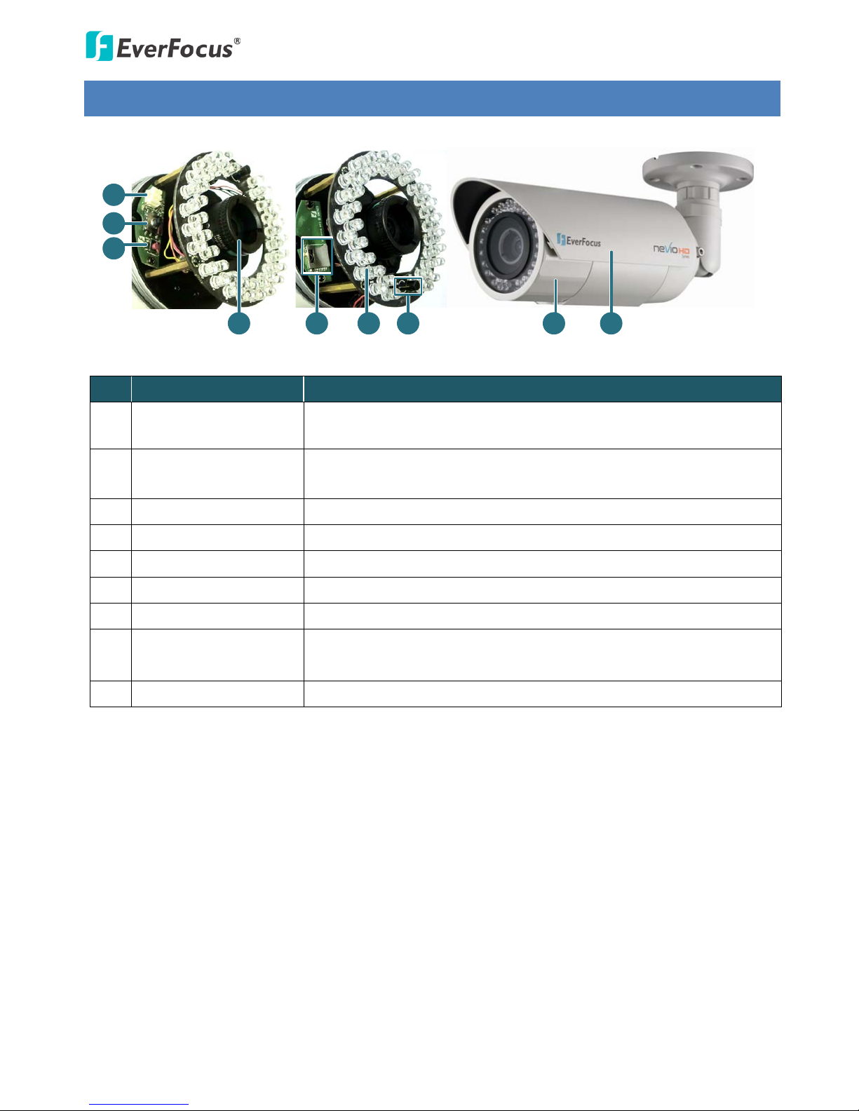
No. Name Description
1 TV-Out Connector
Connects to a handheld test monitor for adjusting camera focus and
zoom.
2 Focus / Zoom Control
Press this control to the left or right to adjust camera focus. To zoom in
/ out the camera view, press this control up or down.
3 Reset Button Resets all configurations to the factory default settings.
4 Lens Varifocal lens.
5 Micro SD / SDHC Slot For inserting a micro SD / SDHC card.
6 IR LEDs 44 IR LEDs for infrared illumination in night vision applications.
7 Light Sensor Detects lights.
8 Camera Cover
Remove the cover for adjusting camera focus and zoom / inserting a
micro SD card or connecting to a handheld test monitor.
9 Sunshield Protect the camera from the direct rays of the sun.
EZN Plus Series
4
4. Installation
4.1 Packing List
Please check that there is no missing item in the package before installing.
• EZN Plus Series Camera x 1 • 4-Pin Terminal Block x 1
• Quick Mounting Ring x 1 • Software CD x 1
• RJ-45 Connector x 1 • Quick Installation Guide x 1
• Mounting Kit x 1
- Long Screw x 4 (for attaching the Quick Mounting Ring to the mounting surface)
- Short Screw x 4 (for connecting the camera base to the quick Mount Ring)
- Screw Anchor x 4 (in conjunction with Long Screw)
- Hexagon Key x 1 (for adjusting the camera position)
- Hexagon Wrench x 1 (for removing the sunshield)
- Torx Wrench x 1 (for removing the lock tab)
- Mounting Template x 1
Note: Contact the shipper if any items appear to have been damaged in the shipping process. If any
items are missing, notify your EverFocus Electronics Corp. Sales Representative or Customer Service
Branch. Please also keep the shipping carton for possible future use.
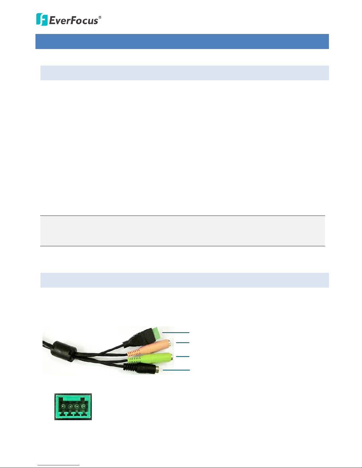
4.2 4- Pin Data Cable
The 4-Pin Data Cable provides connections for power, audio input / output and alarm input / output.
The wires are illustrated and defined below. Note that microphones with external power supplies are
required.
Alarm Input / Output
Audio Input (Pink)
Audio Output (Green)
12V DC Input
Pin Assignment for Alarm Input / Output
4 3 2 1
Pin 1: Alarm GND
Pin 2: Alarm In
Pin3: Alarm Out-
Pin4: Alarm Out+
EZN Plus Series
5
4.3 Basic Installation
This section will introduce the basic installation on mounting / wiring the camera, inserting a micro SD
card and adjusting camera focus / zoom.
4.3.1 Mounting and Wiring
Follow the steps below for mounting and wiring the camera.
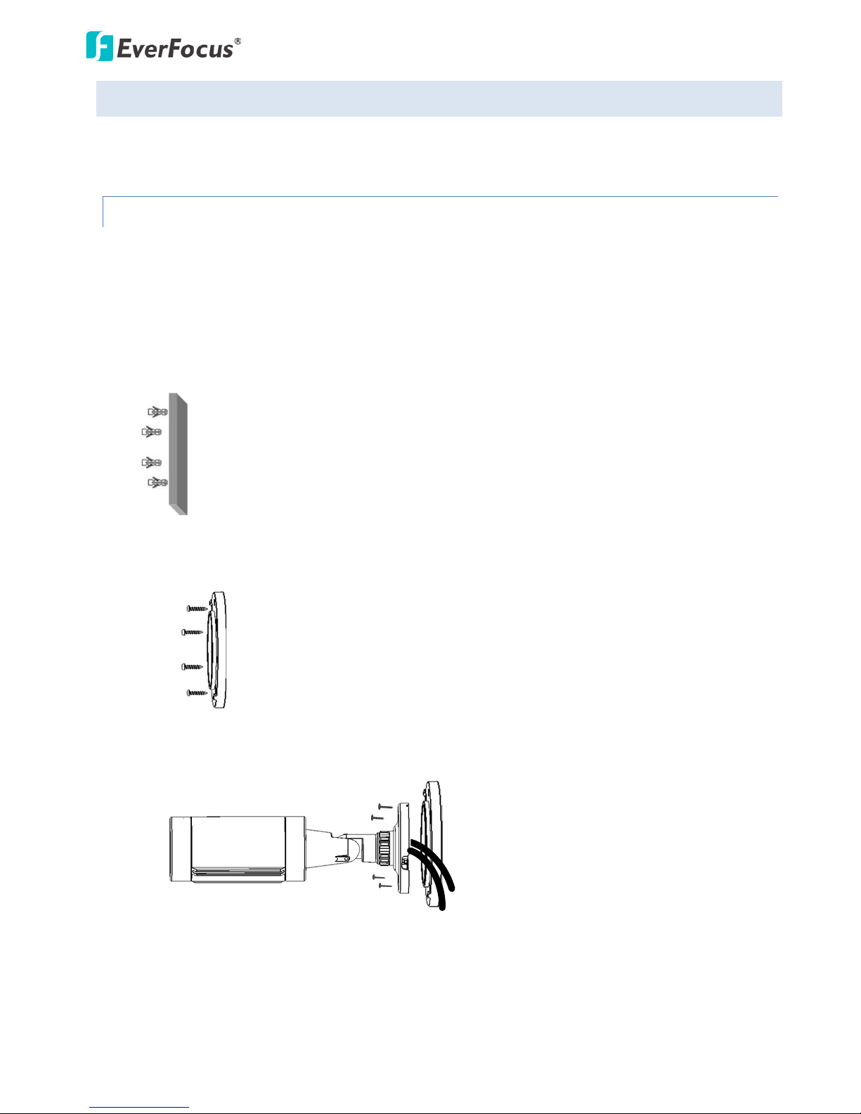
1. Before screwing the camera to the wall, drill four holes on the wall according to the hole-positions
on the supplied Quick-Mounting Ring. If you wish to run the wires into the wall, drill another hole
in the middle of the circular area within the Quick-Mounting Ring.
2. Push the four supplied anchors into the four holes on the wall.
3. Place the Quick-Mounting Ring against the anchoring surface so that the holes line up. Screw the
Quick-Mounting Ring to the wall using the supplied Long Screws.
Quick-Mounting Ring
Long Screws
4. Screw the camera body to the Quick-Mounting Ring using the supplied four Short Screws.
a. If you want to wire the cables from the side of the camera base:
Camera Base Quick-Mounting Ring
Cables
EZN Plus Series
6
b. If you want to wire the cables through the wall, feed the cables through the wall and then
screw the camera base to the Quick-Mounting Ring.
Camera Base Quick-Mounting Ring
Cables
5. Connect the network, power and other cables of the camera to the related devices. Please refer to
4.2 4-Pin Data Cable.
6. Optionally insert a micro SD / SDHC card into the card slot. Please refer to 4.3.2 Inserting a Micro
SD Card.
7. Access the camera live view. Please see 5. Assigning an IP Address. Or connect a handheld test
monitor to the TV-out connector on the camera module for setting image zoom and focus. Please
refer to 4.3.3 Adjusting Camera Focus / Zoom.
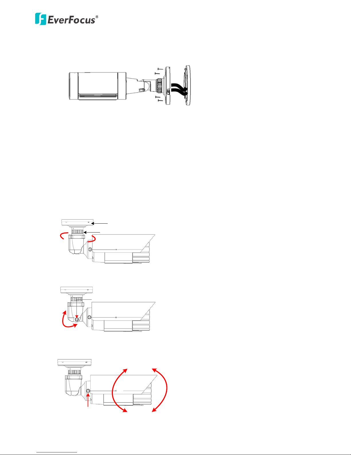
8. Adjust the camera angles.
Pan Adjustment: Twist the Base Disk forcefully until it unscrews from the Lock Ring. Rotate the
camera 360° to the desired position and then screw the Lock Ring until it locks against the Base
Disk.
Base Disk
Lock Ring
360
°
Tilt Adjustment: Loosen the Tilt Screw using the provided hexagon key and adjust the tilt angle
90°.
90
°
Tilt Screw
Rotational Adjustment: Loosen the Rotate Screws on both side of the camera body using the
providing hexagon key and rotate the camera 360° (180° to the left / 180° to the right).
180
°
Rotate Screw
°
°
180
°
EZN Plus Series
7
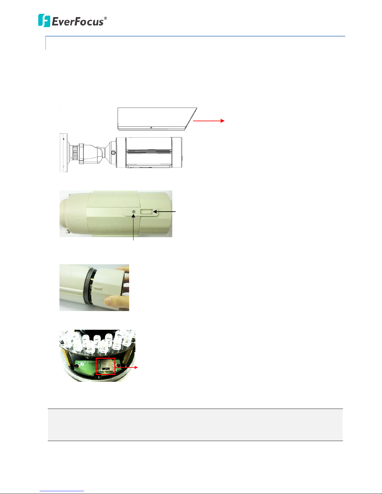
4.3.2 Inserting a Micro SD Card
You can optionally insert a micro SD card into the card slot on the camera module for recording videos.
1. Remove the Sunshield from the camera. Loosen the screw on the Sunshield using the provided
hexagon wrench. Slide the Sunshield out from the rail on the camera body.
Screw
Sunshield
Camera Body
2. Unscrew the Fix Screw using the provided torx wrench and then remove the Lock Tab.
Lock Tab
Fix Screw
3. Rotate and then remove the camera cover.
4. Insert a micro SD card into the card slot.
Micro SD Card Slot
5. Slide the Sunshield back to the camera body.
Note: When properly installed, the rear-side of the Sunshield should be even with the rear-side of
the camera body. Extending the Sunshield in order to shade the lens will compromise the image
quality.
EZN Plus Series
8
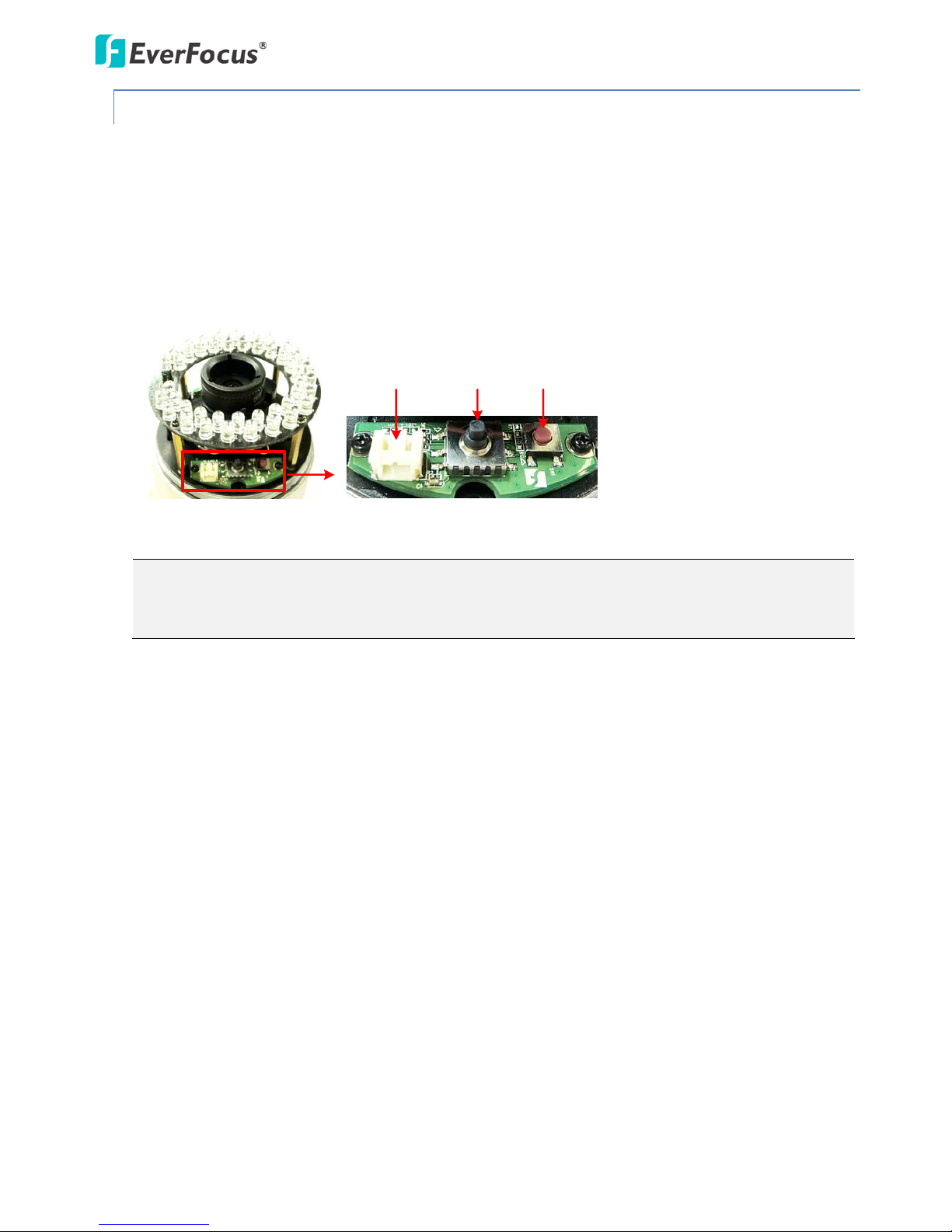
4.3.3 Adjusting Camera Focus / Zoom
After wiring the cables, you can adjust the camera focus and zoom for better image quality.
1. Follow Steps 1 ~ 3 in 4.3.2 Inserting a Micro SD Card to remove the camera cover.
2. Connect the power cable of the camera to the power source.
3. Connect a handheld test monitor to the TV-out connector for setting image zoom and focus.
4. To adjust camera focus, push the Focus / Zoom Control to the left or right. To zoom in / out the
camera, push the Focus / Zoom Control up or down.
Reset
Button
TV-Out
Connector
Focus / Zoom
Control
5. Slide the Sunshield back to the camera body.
Note: When properly installed, the rear-side of the Sunshield should be even with the rear-side of
the camera body. Extending the Sunshield in order to shade the lens will compromise the image
quality.
EZN Plus Series
9
5. Accessing the User Interface
This section explains how to access the Web interface of the camera for configuration.
5.1 Assigning an IP Address
You have to assign an IP address for your camera to be accessible. To assign an IP address to the camera,
use the IP Utility (IPU) software included in the software CD. Please connect the IP camera in the same
LAN of your computer.
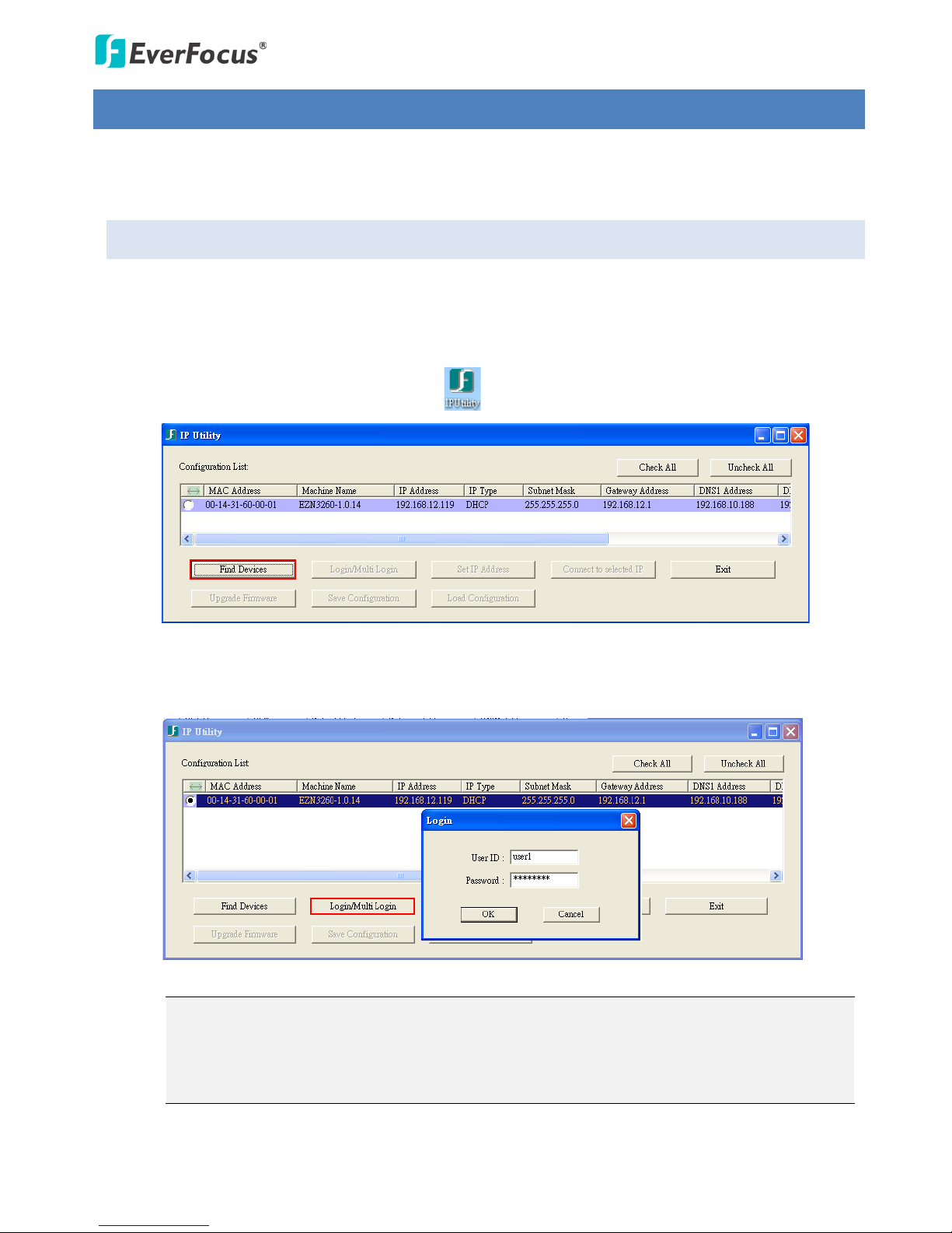
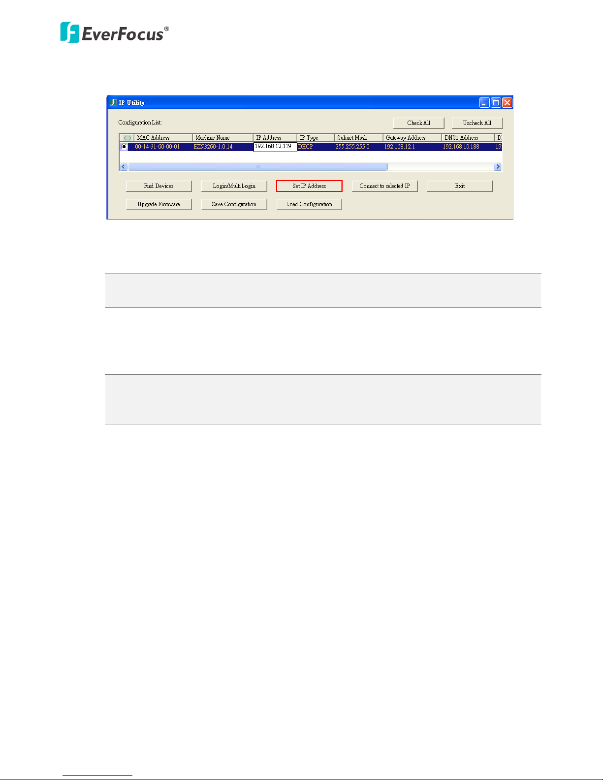
1. Install and then start the IPU program . The following dialog box appears.
2. Click Find Devices to search the cameras connected in the LAN. The default network values of
the cameras will be displayed. By default, the network protocol of the camera is DHCP.
3. To configure the network settings, select a camera and then click Login/Multi Login to log in.
4. Type the user ID and password. Click OK.
Note:
1. The default user ID is user1 and the default password is 11111111.
2. If you select more than one camera that has the same user ID / password, you will be able
to log in several cameras at once.
EZN Plus Series
10
5. To change the IP address, double-click the IP Address of the camera. Type a new IP address and
then click Set IP Address to save the settings.
You can also change the other settings by double-clicking the values. After configuring the values,
click Save Configuration.
Note: Most networks support DHCP protocol, but if you are unsure of your network protocol,
please consult your IP administrator for network configuration details.
6. To access the camera, highlight the camera and click Connect to Selected IP. The Internet
Explorer window pops up.
7. Type the user ID and password to log in. The Live View window of the camera appears.
Note: You might be required to download ActiveX, which is required to view the camera feed.
If asked, click "Yes". For more details on setting up the Microsoft Internet Explorer, please
refer to 5.2 Settings for Microsoft Internet Explorer.
EZN Plus Series
11
5.2 Settings for Microsoft Internet Explorer
To enable Remove Live View, Firmware Upgrade and ActiveX Prompt on Internet Explorer, some
settings have to be complete. Please follow the steps below:
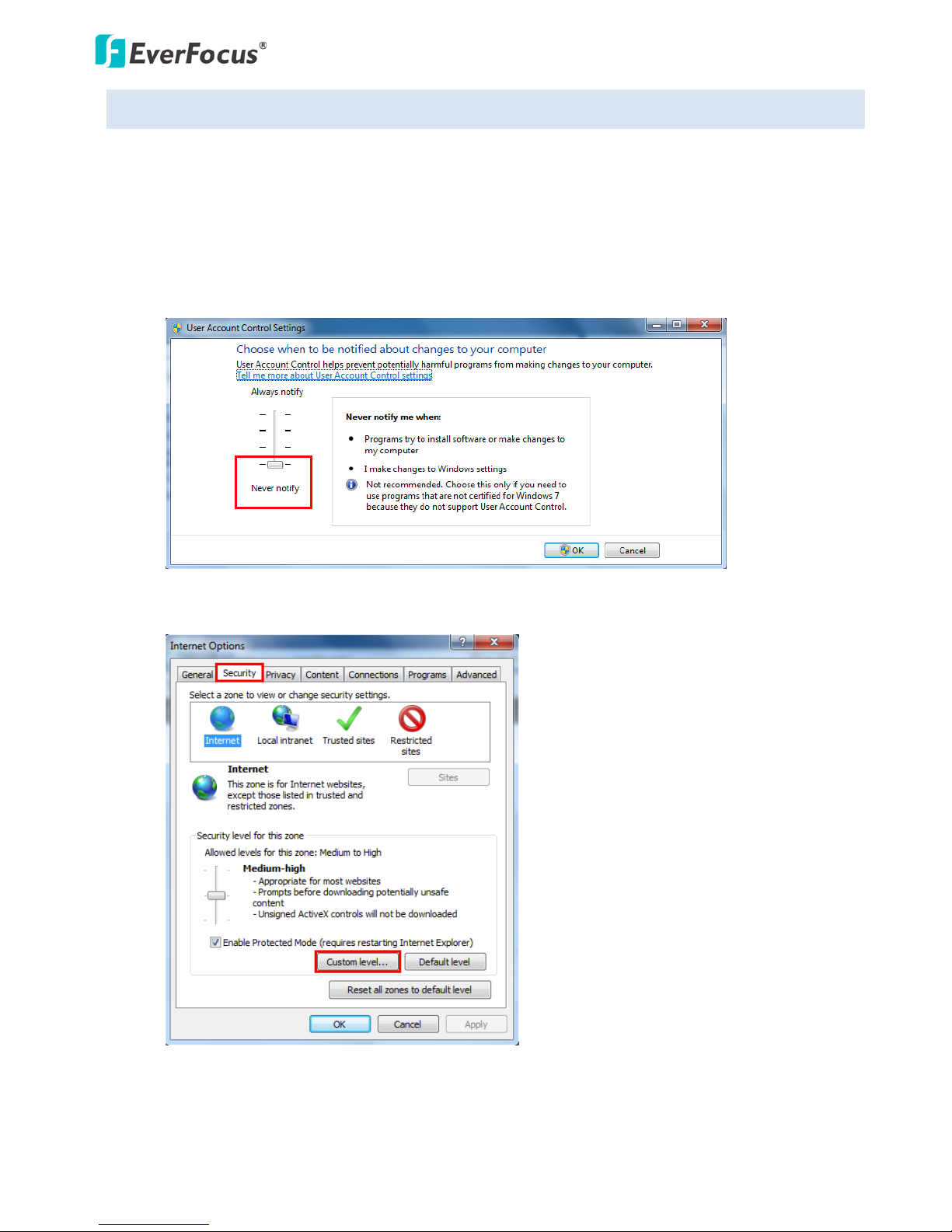
1. On the computer, click Start > Control Panel > System and Security > Action Center (click Change
User Account Control Settings), the User Account Control Settings window appears. Adjust the
slide bar to Never Notify and then click OK. Restart your computer if requested.
2. Open the Internet Explore, click Tools > Internet Options > Security Tab > Custom Level, the
Security Settings windows appears.
EZN Plus Series
12
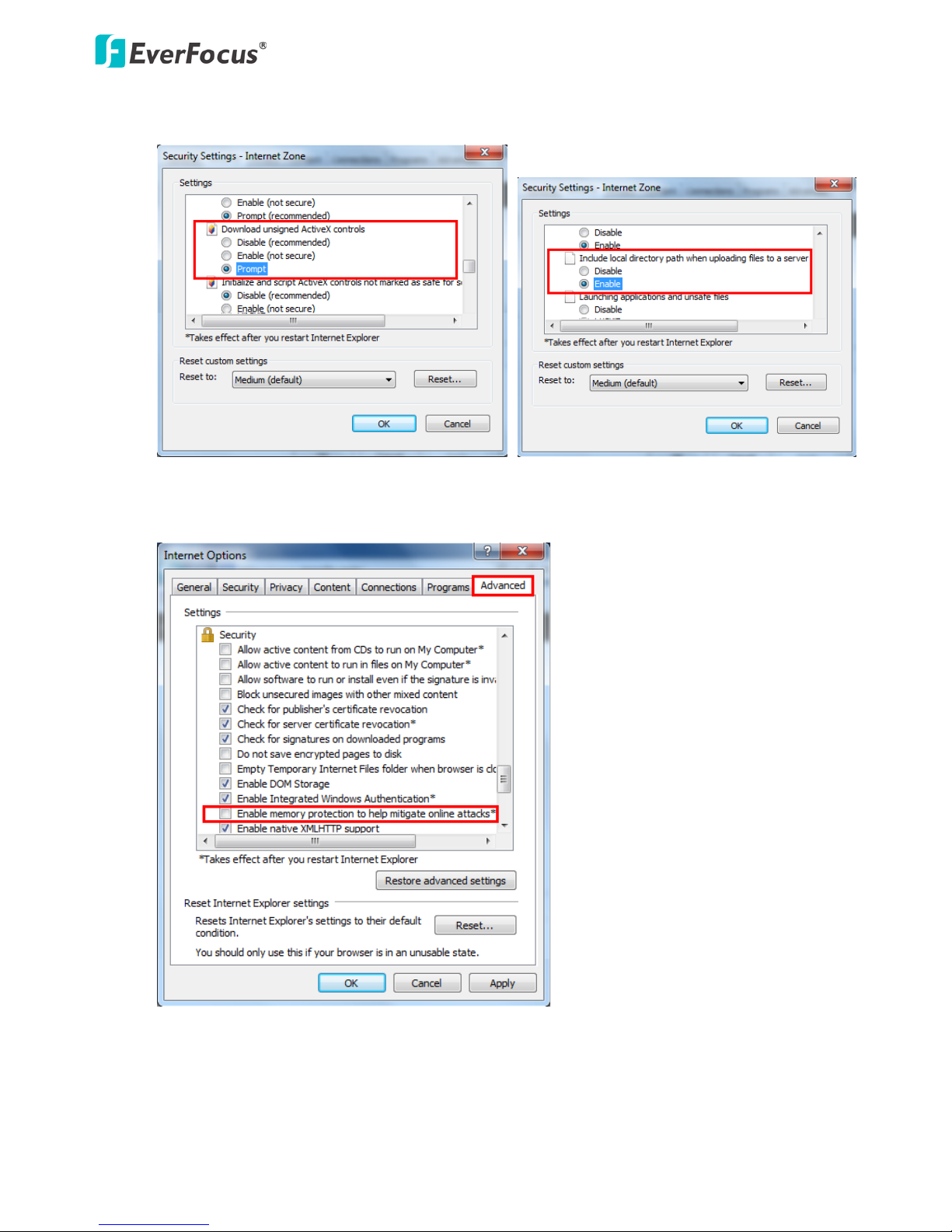
3. In the Download unsigned ActiveX controls field, select Prompt. In the Include local directory
path when uploading files to a server field, select Enable. Click OK.
4. In the Internet Options window, click the Advanced tab and then disable Enable memory
protection to help mitigate online attacks. Click OK.
EZN Plus Series
13
5.3 Connecting the Camera to the Network
There are three methods to connect the IP camera to the network: Router or LAN Connection, Direct
High-Speed Connection and One-to-One Connection.
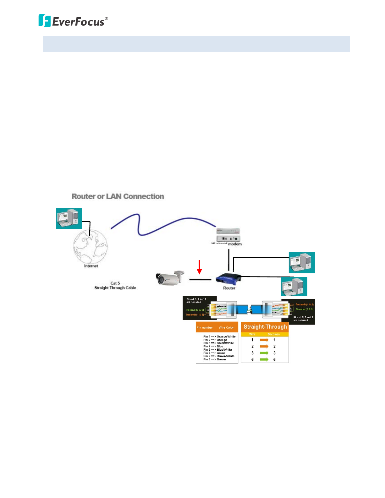
Router or LAN connection
This is the most common connection in which the IP camera is connected to a router and allows
multiple users on and off site to see the IP camera on a LAN/WAN (Internet). The camera must be
assigned an IP address that is compatible with its LAN. By setting up port forwarding on the router, you
can remotely access the cameras from outside of the LAN via the Internet. To remotely access the Web
interface of the IP camera, please refer to 7.3.2 DDNS. To set up port forwarding, please consult the
manual of the router.
Right: Pinout of a straight-through cable.
EZN Plus Series
14
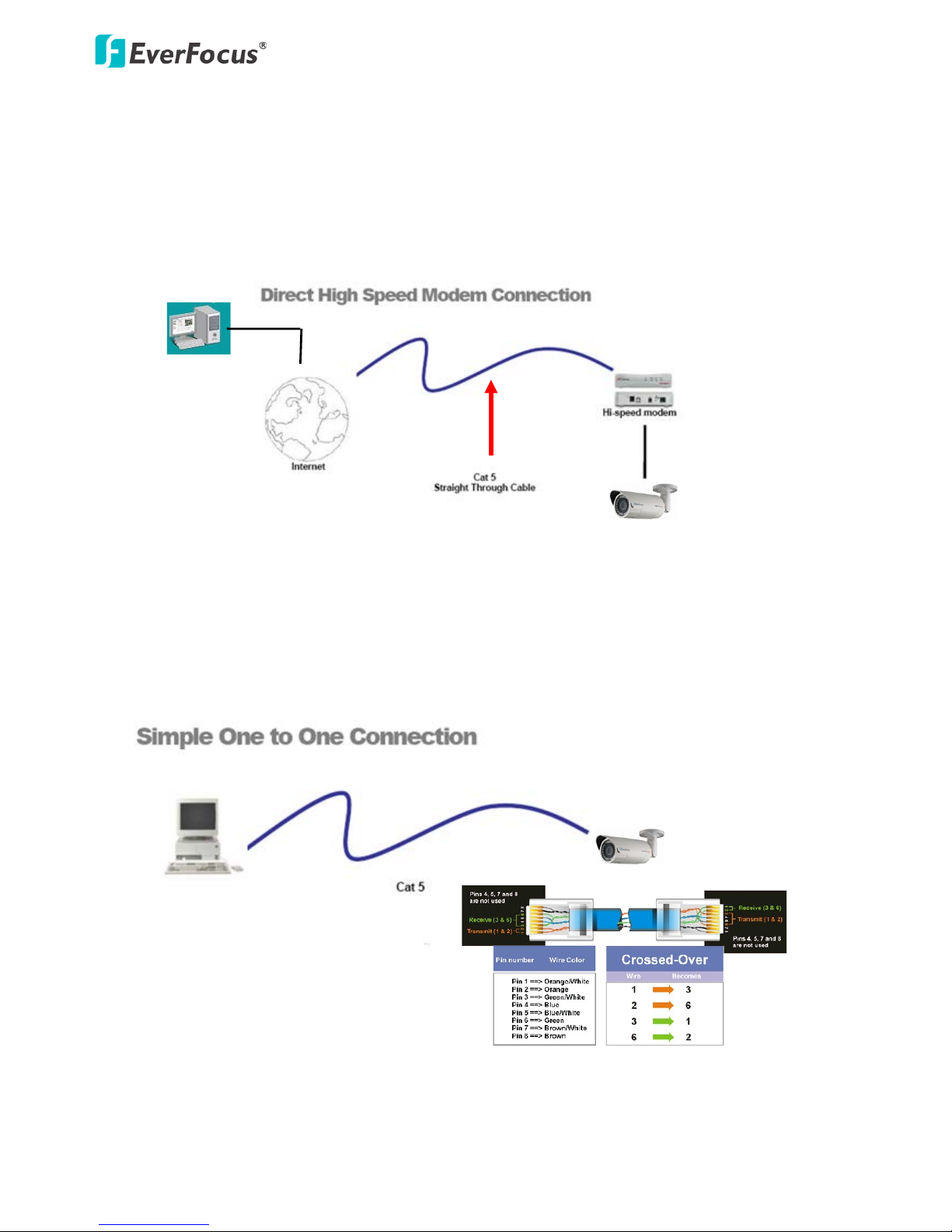
Direct High-Speed Connection
In a Direct High-Speed Connection, the camera connects directly to a modem without the need for a
router. You need to set the static or dynamic WAN IP address assigned by your ISP (Internet Service
Provider) in the camera’s configuration web pages. To access the camera, just type “http://xxx”, where
xxx is the IP address given by your ISP. If you have a dynamic IP address, this connection may require
that you use DDNS for a reliable connection. Please refer to 7.3.2 DDNS.
One-to-One Connection (Directly from PC to IP Camera)
You can connect directly without using a switch, router or modem. However, only the PC connected to
the camera will be able to view the IP camera. You will also have to manually assign a compatible IP
address to both the computer and the IP camera. Unless the PC has another network connection, the IP
camera will be the only network device visible to the PC. See the diagram below:
Pinout of straight patch cable
Right: Pinout of a crossed-over cable.
EZN Plus Series
15
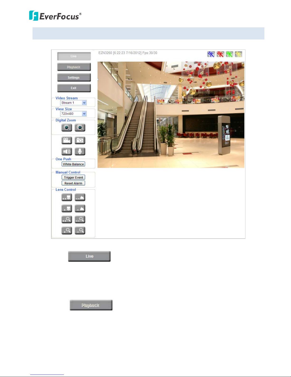
5.4 Live View Window
1. Press the button to display the "Live View" window. Double-click on the
image to show a full-screen display, double-click again or press ESC to return to the normal display.
If you experience video feed lag time (if connected via Internet), you can reduce the resolution or
limit the number of streams. See 7.4.1 Multi Streaming.
2. Press the button to play the recorded data directly from the on-camera Micro
SD / SDHC card (for this function to become active, you have to insert a Micro SD / SDHC card in the
Micro SD / SDHC card slot on the rear panel of the camera. See 7.8.3 SD Card).
EZN Plus Series
16
3. Press the button to enter the Settings page. On the Settings page, there are
8 submenu sections: [System Info], [User Config], [Network], [Video], [Audio], [User], [Event] and
[System]. Click on the section buttons to open their configuration fields. See the Settings section
below for more information.
4. Press the button to exit the system and close this browser page.
5. Video Stream
Select the Video Stream (Stream 1, Stream 2 or Stream 3) that will be displayed in the video box on
the right. Stream 2 and Stream 3 are only selectable if you have enabled the stream. The default
setting is Stream 1 only. See 7.4.1 Multi Streaming.
6. View Size
Use this to select the appropriate view size and shape of the video box on the right. A smaller size
might increase transmission speed and video quality.
7. Digital Zoom
Click the Zoom In / Zoom Out buttons or roll the mouse wheel to zoom in / out the camera live view
up to 10x. Clicking on a magnified image will re-center the image around that point.
8. One Push
This function is only available for EZN3160 Plus / 3260 Plus. The One Push button can be displayed
on the live view window by enabling the Show One Push Buttons function on the User Config < Live
View Config Setting page (see 7.2.1 Live View Config). To enable the button (turned from faded to
clear), on the Video < Advanced Setting page, select One Push from the White Balance Settings
Mode drop-down list, and click the Apply button. Once this is done, pressing the One Push button
on the Live View Window will instruct the camera to adjust the white balance settings, and these
settings will be active until the button is pushed again. This is like a “semi-automatic” way to adjust
white balance to suit the user, if the Auto or Manual mode does not give the result the user wants.
9. Record
The Record button is used to record the current video stream. Click the Record button to start /
stop recording. This icon is only for one-minute video recording. To record long-period recordings,
please set a recording schedule (See 7.7.5 Schedule). The location on your computer, where the
image files will be saved to, and file size can be specified in the submenu (see 7.2 User Config).
EZN Plus Series
17
10. Snapshot
Click the Snapshot button to save a snapshot of the video image currently being displayed. The
location on your computer where the snapshot data will be saved can be specified in “Settings >
User Config” (see 7.2 User Config).
11. Play Audio / Transmit Audio
Click the “Play Audio” (speaker) and “Transmit Audio” (microphone) buttons to switch the sound
on/off for the speaker and microphone, respectively (if such external devices have been connected
to the camera directly or via the network).
12. Manual Control
– Trigger Event
Press the “Trigger Event” button to trigger an event directly from the Live View window. If you have
configured an event (in the Event submenu) that will trigger a reaction (like a recording) when a
Manual Trigger event occurs, clicking this button will trigger that reaction. You can select what that
reaction will be. You can, for instance, set the camera to record the audio/video feed to the SD card
on board the camera. You can then click on the Playback button to open the Playback page and
search for and play all such recordings that had been stored on the card. Such event actions will be
effective once they have been configured in the “Event” menu (see 7.7 Event).
– Reset Alarm
Press the “Reset Alarm” button to reset the alarm output remotely.
13. Lens Control
These buttons control the lens actions. Click the icon to focus closer quickly. Click the
icon to focus closer slowly. Click the icons to focus farther quickly or slowly. Click the
icons to zoom in quickly or slowly. Click the icons to zoom out quickly or slowly.
14. Status Display (info line that can be placed above video box or at bottom of page)
This shows the name of the camera that is currently active or being configured, current date/time
and current frame rate. You can activate these info displays in the Settings > User Config page (see
7.2 User Config).
 Loading...