

EverFocus EZN7221, EZN7360, EZN7260 Quick Installation Manual
Star Light Outdoor Bullet IR Network Camera
EZN7221/7260/7360
Ultra Low Light Network Camera
Quick Installation Guide
Copyright © EverFocus Electronics Corp.
Release Date: March, 2016

EZN7221/7260/7360
1
1
2
4 5 63
1. Physical Description
No. Name Description
1 Micro SD / SDHC Slot For inserting a micro SD / SDHC card.
Resets all configurations to the factory default settings. Press
2 Reset Button
and hold the Reset Button for 5 seconds.
3 IR LEDs 44 IR LEDs for infrared illumination in night vision applications.
4 Lens 3.3 – 10 mm, auto focus, varifocal, F1.3 – 360C.
5 Light Sensor Detects lights.
6 Sunshield Protect the camera from the direct rays of the sun.
Dimensions
1
EZN7221/7260/7360
•
•
System Requirements
Before installing, please check that your computer meets the following system requirements.
Operating System Windows 7 (32 and 64-bit) or above
CPU
Intel Core i5 CPU @ 2.0GHz (or equivalent AMD) or higher
(Intel Core i7 CPU @ 3.4GHz recommended)
Graphic Card 512MB RAM graphic cards (or equivalent on-board graphic cards)
2GB or more (8GB recommended)
RAM
• Additional HD space depends on required local storage of video files,
100 Mbps network card.
DirectX 9.0c
Software
• Internet Explorer 9 and later, Firefox 4.0-9.0, Chrome (Windows
version 44 and earlier)
Packing List
Please check that there is no missing item in the package before installing.
• EZN Series Camera x 1 • Power Pigtail Cable x 1
• Cable Gland Kit x 1 (connect to the • Plug x 1 (inserting to the Quick Mounting Ring for
LAN/PoE cable for waterproofing) through-the-wall installation)
• Quick Mounting Ring x 1 • Software CD x 1
• MAC Address Sticker x 2 • Quick Installation Guide x 1
• Mounting Kit x 1
- Long Screw x 4 (for attaching the Quick Mounting Ring to the mounting surface)
- Short Screw x 4 (for connecting the camera base to the Quick Mount Ring)
- Screw Anchor x 4 (in conjunction with Long Screw)
- Hexagon Wrench x 1 (for adjusting the camera position)
- Thinner Hexagon Wrench x 1 (for removing the Sunshield)
- Desiccant Bag x 1
Note:
1. Equipment configurations and supplied accessories vary by country. Please consult your
local EverFocus office or agents for more information. Please also keep the shipping
carton for possible future use.
2. Contact the shipper if any items appear to have been damaged in the shipping process.
2
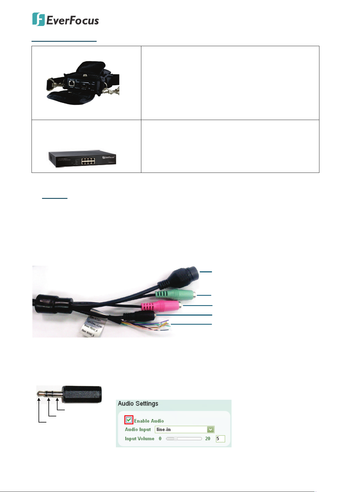
Optional Accessory
12VDC Input
LAN / PoE Cable
Audio Input (TRS Line-in) (Pink)
Audio Output (TRS Line-out) (Green)
Cable Assembly
Gray: CVBS OUT
White: 24VAC+
Light Green: 24VACBrown: RS485_A
Black: RS485_B
Yellow: GND
Green: Alarm OUT
Pink: Alarm COM
Purple: Alarm IN
TRS Connector
Left Channel (Tip)
Right Channel (Ring)
Ground (Sleeve)
EZN7221/7260/7360
• IP Sidekick - ESK1000
Using it for installation, you do not need to pre-configure
the IP address or to use an additional monitor to check and
adjust all the IP cameras. The product can assign an IP
address to the camera through its Wi-Fi network, then you
can connect and check the camera live view using our
mobile app. For details about IP Sidekick, please refer to the
IP Sidekick – ESK1000 User’s Manual.
• EverFocus 5 / 8 / 16 / 24 Ports
PoE Switch
5 Ports: ES0501-40
8 Ports: ES0812-31 / ES0802-41
16 Ports: ES1625-31 / ES1645-51
24 Ports: ES2426-31 / ES2446-51 / ES2448-62
2. Cables
The Cables provide connections for Network, GND, CVBS output, power, audio input / output and
alarm input / output. Note that the audio-in / out cable features a line 3.5mm jack (TRS). Be sure to
prepare microphones / speakers with TRS connector (see TRS Connector image below). Also,
microphones / speakers with a (built-in) amplifier and external power supply are required.
To activate the Audio function, the Enable Audio must be checked.
See 7.2.1 Streaming and Audio.
3
EZN7221/7260/7360
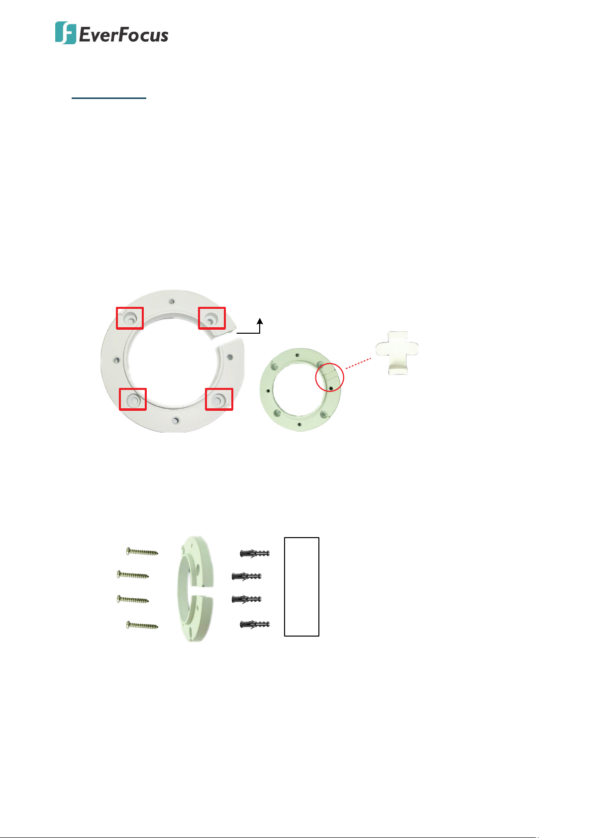
Circular Area
This conduit Is for wiring the cables along
the wall installation.
If you want to wire the cables through the wall,
then this conduit will not be used. You can
insert the supplied Plug into the conduit.
Plug
Wall
Anchors
Quick-Mounting Ring
Long Screws
3. Installation
This installation guide provides the basic instructions on installing an EZN bullet IP camera. For
details, please refer to the User’s Manual in the software CD.
3.1 Mounting and Wiring
Follow the steps below for mounting and wiring the camera.
1. Before screwing the camera to the wall, drill four holes on the wall according to the
hole-positions on the supplied Quick-Mounting Ring. If you wish to run the wires into the
wall, drill another hole in the middle of the circular area within the Quick-Mounting Ring.
2. Push the four supplied Anchors into the four holes on the wall. Place the Quick-Mounting
Ring against the anchoring surface so that the holes line up. Screw the Quick-Mounting
Ring to the wall using the supplied Long Screws.
4
EZN7221/7260/7360
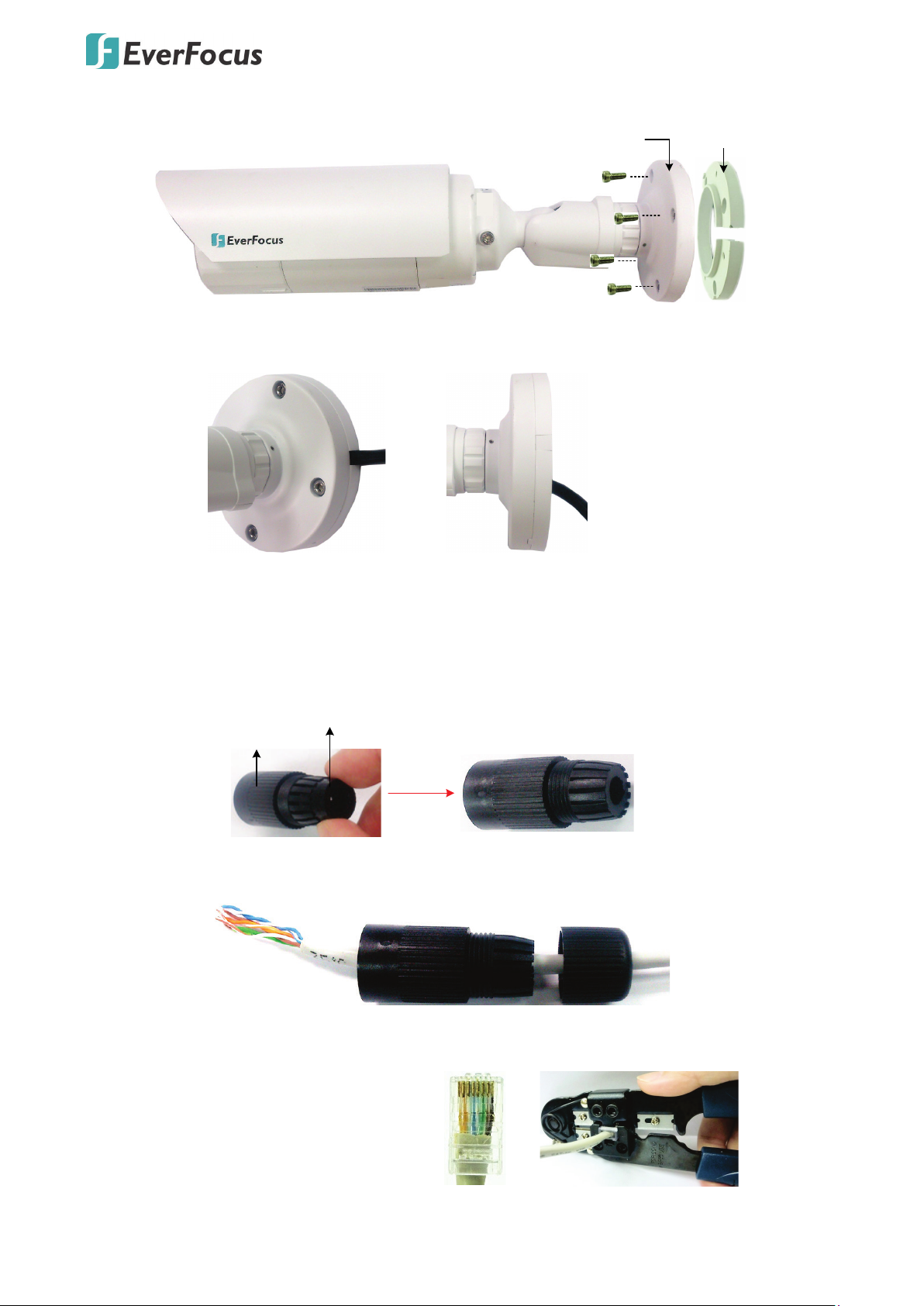
Quick
-
Mounting Ring
Short Screws
Camera Base
Short Screws
Wire the cables from the side
of the camera
Wire the cables through the wall
Cable Gland
Stopper
Cable Gland Screw Cap
Orange with white stripe
Orange
Green with white stripe
Blue
Blue with white stripe
Green
Brown with white stripe
Brown
3. Screw the camera base to the Quick-Mounting Ring using the supplied four Short Screws.
You can wire the cables from the side of the camera or through the wall.
4. Connect the network, power and other cables of the camera to the related devices.
• If you want to use the Cable Gland to connect the network cable for waterproofing:
a. Insert the supplied Stopper to the Cable Gland.
b. Insert a RJ-45 network cable (without the RJ-45 connector on the one end)
through the Screw Cap and Cable Gland.
c. Crimp the RJ-45 connector onto the network cable. Note that the wires should be
placed into the RJ-45 connector based on the following order (from left to right).
5
 Loading...