

Page 1

EHN Series
EZN Series
Value IP Series Network Camera
2MP/5MP/8MP, H265, IR & WDR
User’s Manual
Copyright © EverFocus Electronics Corp.
Release Date: May, 2019
Page 2

Copyright 1995-2019 EverFocus Electronics Corp.
Disclaimer
All the images including product pictures or screen shots in this document are for example only. The images
may vary depending on the product and software version. Information contained in this document is subject
to change without notice.
Copyright
All rights reserved. No part of the contents of this manual may be reproduced or transmitted in any form or by
any means without written permission of the EverFocus Electronics Corporation.
EverFocus
2F., No.12, Ln. 270, Sec. 3, Beishen Rd., Shenkeng Dist.,
New Taipei City 222, Taiwan
TEL: +886 2 2662 2338
FAX: +886 2 2662 3632
www.everfocus.com.tw
Page 3

About this document
All the safety and operating instructions should be read and followed before the unit is operated. This
manual should be retained for future reference. The information in this manual was current when
published. The manufacturer reserves the right to revise and improve its products. All specifications are
therefore subject to change without notice.
Regulatory Notices
FCC Notice "Declaration of Conformity Information"
This equipment has been tested and found to comply with the limits for a Class A digital device,
pursuant to part 15 of the FCC Rules. These limits are designed to provide reasonable protection against
harmful interference in a residential installation. This equipment generates, uses and can radiate radio
frequency energy and, if not installed and used in accordance with the instructions, may cause harmful
interference to radio communications. However, there is no guarantee that interference will not occur in
a particular installation. If this equipment does cause harmful interference to radio or television
reception, which can be determined by turning the equipment off and on, the user is encouraged to try
to correct the interference by one or more of the following measures:
- Reorient or relocate the receiving antenna.
- Increase the separation between the equipment and receiver.
- Connect the equipment into an outlet on a circuit different from that to which the receiver is
connected.
- Consult the dealer or an experienced radio/TV technician for help.
Warning: Changes or modifications made to this equipment, not expressly approved by EverFocus or
parties authorized by EverFocus could void the user's authority to operate the equipment.
This device complies with part 15 of the FCC Rules. Operation is subject to the following two conditions:
(1) This device may not cause harmful interference, and
(2) This device must accept any interference received, including interference that may cause undesired
operation.
Value IP Series camera complies with CE and FCC.
i
Page 4

Precautions
Do not install the camera near electric or magnetic fields.
Install the camera away from TV/radio transmitters, magnets, electric motors, transformers and audio
speakers since the electromagnetic fields generated from these devices may distort the video image or
otherwise interfere with camera operation.
Never disassemble the camera beyond the recommendations in this manual nor introduce materials
other than those recommended herein.
Improper disassembly or introduction of corrosive materials may result in equipment failure or other
damage.
Try to avoid facing the camera toward the sun.
In some circumstances, direct sunlight may cause permanent damage to the sensor and/or internal
circuits, as well as creating unbalanced illumination beyond the capability of the camera to compensate.
1. Keep the power cord away from water and other liquids and never touch the power cord with wet
hands.
Touching a wet power cord with your hands or touching the power cord with wet hands may result in
electric shock.
2. Never install the camera in areas exposed to oil, gas or solvents.
Oil, gas or solvents may result in equipment failure, electric shock or, in extreme cases, fire.
3. Cleaning
For cameras with interchangeable lenses, do not touch the surface of the sensor directly with the
hands. Use lens tissue or a cotton tipped applicator and ethanol to clean the sensor and the camera
lens. Use a damp soft cloth to remove any dirt from the camera body. Please do not use complex
solvents, corrosive or abrasive agents for cleaning of any part of the camera.
4. Do not operate the camera beyond the specified temperature, humidity or power source ratings.
Use the camera at temperatures within -30°C ~ 55°C / -22°F ~ 131°F, and humidity ≤ 95%; this device
is not rated as submersible. The input power source is 12VDC / PoE. Be sure to connect the proper + /
- polarity and voltage, as incorrect polarity or too high a voltage will likely cause the camera to fail,
and such damage is not covered by the warranty. The use of properly fused or Class 3 power limited
type supplies is highly recommended.
5. Mounting
Use care in selecting a solid mounting surface which will support the weight of the camera plus any
wind, snow, ice or other loading, and securely attach the camera to the mounting surface using
screws and anchors which will properly support the camera. If necessary (e.g. when mounting to
drop ceilings) use a safety wire to provide additional support for the camera.
ii
Page 5

CONTENTS_Toc3288504
1. Introduction 1
1.1 System Requirement ..................................................................................................................... 2
1.2 Features ........................................................................................................................................ 2
1.3 Packing List .................................................................................................................................... 3
2 Physical Description 4
2.1 Dimensions ................................................................................................................................... 5
2.2 Cables ............................................................................................................................................ 5
3 Installation 7
3.1 EHN Series ..................................................................................................................................... 7
3.2 EZN Series ..................................................................................................................................... 9
4 Accessing the Camera 10
4.1 Checking the Dynamic IP Address .............................................................................................. 10
4.2 Settings for Microsoft Internet Explorer ..................................................................................... 12
4.3 Connecting the Camera to the Network ..................................................................................... 13
5 Live View Window 15
5.1 Playback ...................................................................................................................................... 16
5.1.1 Playback Panel ................................................................................................................ 17
5.1.2 Download ........................................................................................................................ 18
5.2 Display Setting ............................................................................................................................ 19
5.2.1 Live .................................................................................................................................. 19
5.2.2 Image .............................................................................................................................. 20
5.2.2.1 Hallway Display .............................................................................................. 22
5.2.3 Privacy Mask ................................................................................................................... 23
5.2.4 Audio ............................................................................................................................... 24
5.2.5 ROI .................................................................................................................................. 25
5.3 Record ......................................................................................................................................... 26
5.3.1 Record Setting ................................................................................................................. 26
5.3.2 Record Schedule ............................................................................................................. 27
5.4 Alarm Setting .............................................................................................................................. 28
5.4.1 Motion ............................................................................................................................ 28
5.4.2 I/O ................................................................................................................................... 29
5.4.3 Tamper Alarm ................................................................................................................. 30
5.4.4 Sound Detection ............................................................................................................. 31
5.5 Network Setting .......................................................................................................................... 32
iii
Page 6

5.5.1 Network .......................................................................................................................... 32
5.5.2 Video Streaming ............................................................................................................. 34
5.5.3 Email ............................................................................................................................... 35
5.5.4 DDNS ............................................................................................................................... 36
5.5.5 IP Filter ............................................................................................................................ 37
5.5.6 RTSP ................................................................................................................................ 38
5.5.7 FTP .................................................................................................................................. 39
5.5.8 SNMP .............................................................................................................................. 40
5.5.9 HTTPS .............................................................................................................................. 40
5.6 Storage Setting ............................................................................................................................ 41
5.6.1 Storage ............................................................................................................................ 41
5.6.2 Cloud Storage .................................................................................................................. 42
5.7 System Setting ............................................................................................................................ 44
5.7.1 General ........................................................................................................................... 44
5.7.2 User Account .................................................................................................................. 46
5.7.3 Firmware Upgrade .......................................................................................................... 48
5.7.4 Load Default .................................................................................................................... 48
5.7.5 System Reboot ................................................................................................................ 49
5.7.6 Import and Export .......................................................................................................... 49
5.7.7 Local Settings .................................................................................................................. 50
5.7.8 Log .................................................................................................................................. 51
5.7.9 Info .................................................................................................................................. 52
5.7.9.1 Performing the P2P Function ........................................................................ 52
5.8 Intelligent Setting ........................................................................................................................ 55
5.8.1 Record Schedule ............................................................................................................. 55
5.8.2 Detection ........................................................................................................................ 56
5.8.2.1 Perimeter Intrusion Detection ....................................................................... 56
5.8.2.2 Line-Crossing Detection ................................................................................. 58
5.8.2.3 Object Detection ........................................................................................... 60
5.8.2.4 Pedestrian Detection ..................................................................................... 62
5.8.2.5 Face Detection ............................................................................................... 64
5.8.2.6 Cross-Counting Detection .............................................................................. 66
5.8.3 Analysis ........................................................................................................................... 68
5.9 Color Setting ............................................................................................................................... 69
5.10 Lens Control ................................................................................................................................ 70
5.11 Live View Function Icons............................................................................................................. 71
iv
Page 7

Value IP Series Network Cameras – H265, 2MP / 5MP / 8MP
1. Introduction
The Value IP series H.265 Outdoor IP camera provides 30fps at 2MP / 5MP / 8MP (4K) viewing resolution.
The series supports triple streams from H.265 or H.264 video compression formats. In same resolution, the
H.265 provides higher compression efficiency and lower bitrate comparing with H.264 codec, allowing
more efficient bandwidth and data storage usage. The Wide Dynamic Range function on the other hand
enables the IP camera to provide clear images even under back light circumstances where intensity of
illumination can vary excessively.
The motorized zoom lens models can provide the desired field of view with superior video quality in
precise focus. Equipped with an IP66 weather-proof housing, the Value IP series meets a wide variety of
needs for outdoor surveillance. Except 12VDC power supply, the series also supports Power over Ethernet
(IEEE 802.3af), which eliminates the need for power cables and thus reduce the installation costs.
The Value IP series conforms to ONVIF for compatibility with other network video devices. You can also use
EverFocus Mobile applications to remotely view the live views of the cameras through your iOS or android
handheld devices; or use EverFocus CMS to remotely manage multiple IP devices connected on the
network.
Series 2MP 5MP 8MP
EHN Series EHN1250 EHN2550 EHN2850 / EHN2850-15
EZN2850 / EZN2850-15 /
EZN Series EZN1250 / EZN1240 EZN2550 / EZN2540
EZN2840 / EZN2840-15
Lens Type Models
EHN1250 / EHN2550
2.8~12mm motorized lens
EZN1250 / EZN2550
EHN2850 / EHN2850-15
3.3~12mm motorized lens
EZN2850 / EZN2850-15
3.6mm fixed lens EZN1240 / EZN2540 / EZN2840 / EZN2840-15
For more information on the product specifications, please refer to the datasheet of each product. To
download datasheet, please click Download on each Product page on EverFocus Website
www.everfocus.com.tw
1
Page 8

Value IP Series Network Cameras – H265, 2MP / 5MP / 8MP
1.1 System Requirement
Before installing, please check that your computer meets the following system requirements.
Operating System:
32/64-bit: Windows 7, Windows 8, Windows 2008
32-bit: Windows 2003, Window XP, Windows 2000
CPU: Intel Core Duo II dual-core processor or higher
Memory: 1G or more Video memory: 256M or more
Display: 1024 × 768 or higher resolution
IE: IE 6.0 or higher version
Note: For using the Internet Explorer, some settings are required. Please refer to 4.2 Settings for
Microsoft Internet Explorer.
1.2 Features
• Progressive Scan CMOS sensor
• Equipped with 2.8~12mm motorized lens or 3.6mm fixed lens (depends on model)
• Triple-streaming from H.265 / H.264
• Supports Wide Dynamic Range
• Provides True Day/Night functionality with automatic IR filter operation
• Equipped with IR LEDs
• Supports video analytics
• Supports ONVIF (V17.06, Profile S, Profile G)
• Weather-proof IP66 rated
• Supports micro SD card slot
• Supports live monitoring via mobile Apps (iOS & Android)
• Supports PoE and 12VDC
2
Page 9

Value IP Series Network Cameras – H265, 2MP / 5MP / 8MP
1.3 Packing List
Please check that there is no missing item in the package before installing.
EHN Series EZN Series
1. Camera x 1
2. MAC Address Sticker x 2
3. Cable Gland Kit x 1
4. Screw x 4
5. Screw Anchor x 4
6. Desiccant Bag x 1
7. Torx Wrench x 1
8. Mounting Sticker x 1
1. Camera x 1
2. MAC Address Sticker x 2
3. Cable Gland Kit x 1
4. Screw x 3
5. Screw Anchor x 3
6. Hexagon Wrench x 1
7. Quick Installation Guide x 1
8. Software CD x 1
9. Quick Installation Guide x 1
10. Software CD x 1
Note:
1. Equipment configurations and supplied accessories vary by country. Please consult your local
EverFocus office or agents for more information. Please also keep the shipping carton for possible
future use.
2. Contact the shipper if any items appear to have been damaged in the shipping process.
Optional Accessory
You can go to the product page on EverFocus’ website to check the related optional accessories. Please
click Accessories on each Product page on EverFocus Website www.everfocus.com.tw
3
Page 10

Value IP Series Network Cameras – H265, 2MP / 5MP / 8MP
6
9
10
1
2
4
3
EHN Series
EZN Series
8
7
5
SD Card Slot on
EHN 2MP/5MP Series
2 Physical Description
No. Item Name Descriptions
1 Light Sensor Detects lights.
2 IR LEDs IR LEDs for infrared illumination in night vision applications.
3 Lens Camera Lens.
Micro SD Card Slot
Insert a micro SD card. Please go to the product page on EverFocus website to
4
(for 8MP models)
see the latest Storage Compatibility List. http://www.everfocus.com.tw
Micro SD Card Slot
5
(for 2MP/5MP models)
6 Micro SD Card Slot
Insert a micro SD card. Please go to the product page on EverFocus website to
see the latest Storage Compatibility List. http://www.everfocus.com.tw
Insert a micro SD card. Please go to the product page on EverFocus website to
see the latest Storage Compatibility List. http://www.everfocus.com.tw
7 Sunshield Protect the camera from the direct sun rays.
8 Rotate Screw Loosen the Rotate Screws (on both sides) to adjust the rotating angle.
9 Tilt Screw Loosen the Tilt Screw to adjust the tilting angle.
10 Pan Screw Loosen the Pan Screw to adjust the angle.
4
Page 11
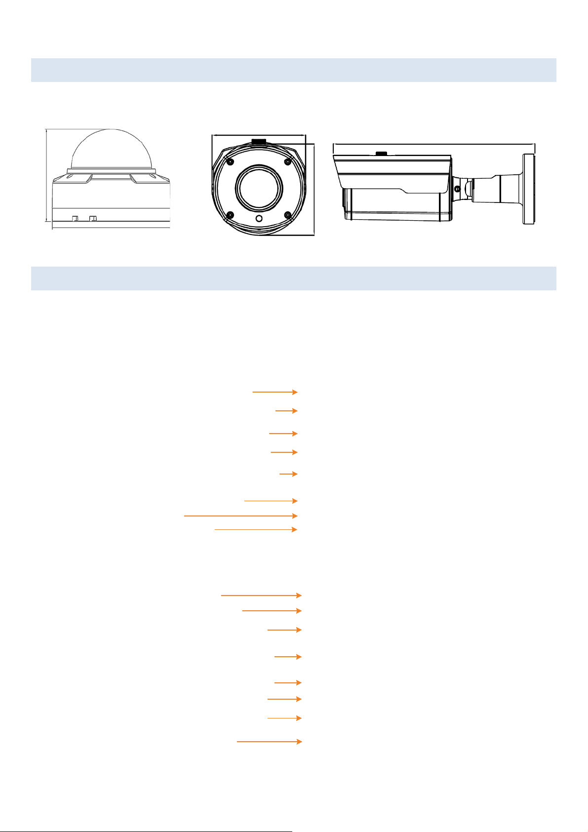
2.1 Dimensions
117.3mm / 4.62"
Ø 147mm / 5.79"
Ø 83.58mm / 3.29"
82.18mm / 3.24"
241.18mm / 9.5"
Alarm Input / Output
LAN / PoE Cable
Video Output (BNC)
12VDC Power Input
Reset Button
Audio Output
Audio Input
Ground
Alarm Input / Output
LAN / PoE Cable
Video Output (BNC)
12VDC Power Input
Reset Button
Audio Output (White)
Audio Input (Red)
Ground
Value IP Series Network Cameras – H265, 2MP / 5MP / 8MP
EHN Series
2.2 Cables
The cables provide connections for network, BNC video output, power, audio input / output and alarm
input / output. A Reset Button Cable is also provided. Please be noted that microphones / speakers with a
(built-in) amplifier and external power supply are required.
EHN Series
EZN Series
EZN Series
5
Page 12

Value IP Series Network Cameras – H265, 2MP / 5MP / 8MP
1
2
3
4
Alarm In
GND
COM
Alarm Out
Note: To activate Audio function, the Audio function must be enabled please refer to 5.5.2 Video
Streaming.
Alarm IO PIN Assignment
Reset Button
The Reset Button can be used to restore the camera to factory default. When the camera is powered up,
press the Reset Button about 8 seconds to reboot the camera.
6
Page 13
Value IP Series Network Cameras – H265, 2MP / 5MP / 8MP
+ +
+
+
+
+
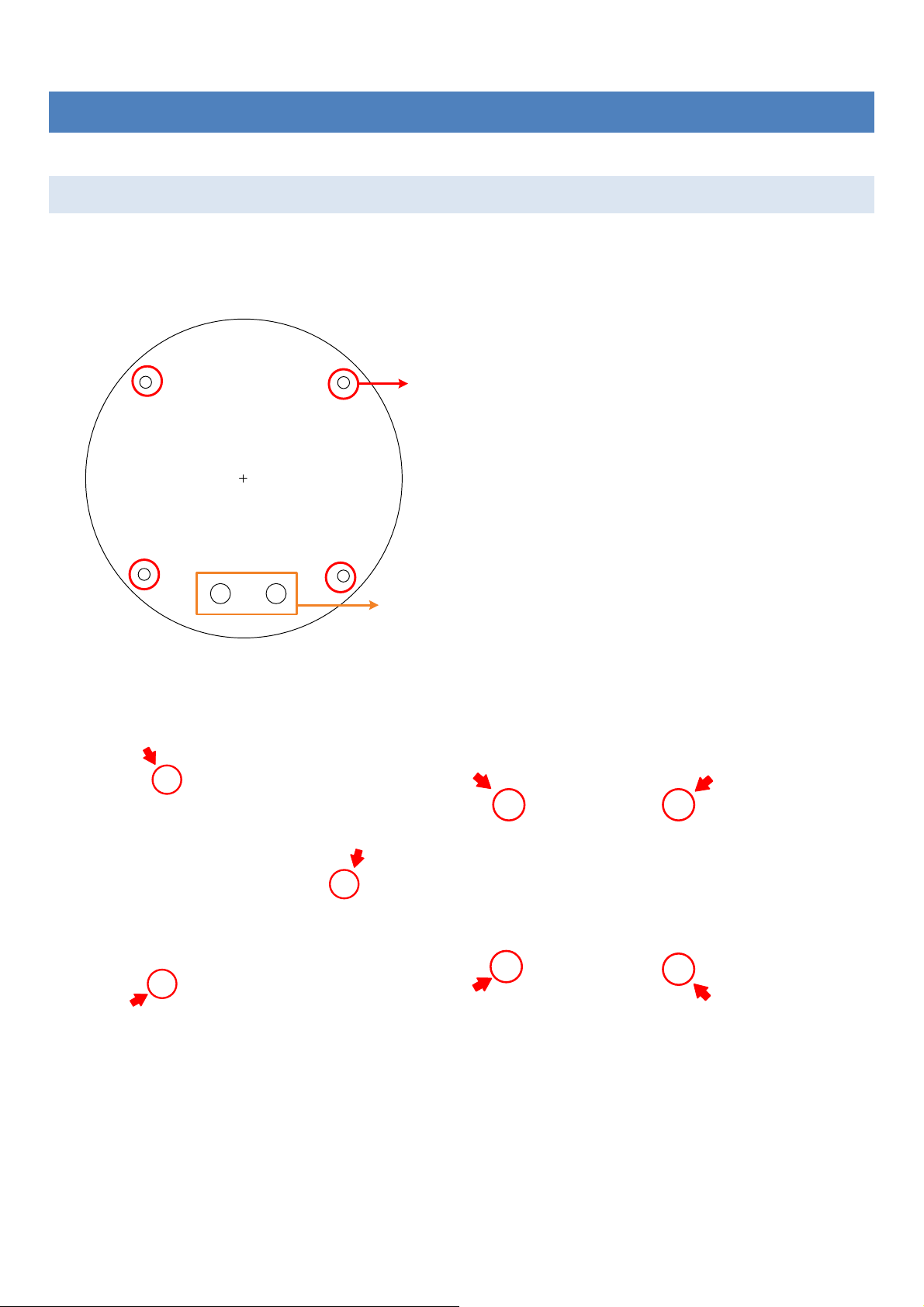
Screw Position x 4
Optionally drill the 2 Cable Holes if you
want to run the cables through the surface.
3 Installation
3.1 EHN Series
1. Stick the supplied Mounting Sticker on the surface to mark the 4 screw positions. Drill the 4
screw-depth holes on the surface and then push the supplied 4 Screw Anchors into the screw holes.
Optionally drill the bottom 2 Cable Holes if you want to run the cables through the surface.
2. Remove the camera cover by unscrewing the 3 cover screws using the supplied Torx Wrench (Left
Image). Screw the camera base to the surface using the supplied 4 Screws (Right Image).
3. Optionally insert a micro SD card into the card slot (please refer to 2. Physical Description).
4. Adjust the pan / tilt / rotate angles of the camera.
5. Connect the camera to power. You can either connect the camera to a 12VDC power source or to a PoE
switch using the PoE cable.
7
Page 14

Value IP Series Network Cameras – H265, 2MP / 5MP / 8MP
Waterproof Ring
Cable Gland
Stopper Screw Cap
RJ-45 Cable
LAN/PoE Cable
Screw Cap
Cable Gland
Orange with white stripe
Orange
Green with white stripe
Blue
Blue with white stripe
Green
Brown with white stripe
Brown
Stick the supplied desiccant bag
Remove the 3 desiccant bags
Note: Please screw back the
Camera Cover immediately
in case of reducing the
absorption capacity of the
desiccant bag inside the
camera body.
6. Connect the camera to the network using the supplied Cable Gland Kit.
a. Insert a RJ-45 network cable (without the RJ-45 connector on the one end) through the supplied
Waterproof Ring, Cable Gland, Stopper and Screw Cap accordingly.
b. Connect the RJ-45 cable to the LAN/PoE Cable of the camera.
c. Tightly screw the Cable Gland and Screw Cap to the Rugged RJ-45 Connector Cable.
d. Crimp the RJ-45 connector onto the RJ-45 network cable. Note that the wires should be placed into
the RJ-45 connector based on the following order (from left to right).
7. Before screwing back the camera cover, remove the 3 old desiccant bags from the inside of Camera
Cover and replace them with the supplied Desiccant Bag. Screw the camera cover back to the camera.
8. Now you can access the camera live view. See 4. Accessing the Camera.
8
Page 15
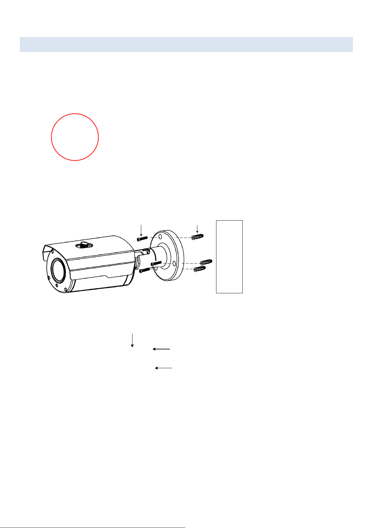
Value IP Series Network Cameras – H265, 2MP / 5MP / 8MP
Screw Anchor
Screw
Surface
Tilt Screw
Pan Screw
Rotate Screws (both sides)
3.2 EZN Series
1 Optionally insert a micro SD card into the card slot on the rear panel of the camera. To do this, unscrew
the 2 screw, remove the SD card slot cover and then insert the micro SD card.
2 Drill three holes on the surface according to the screw positions on the Camera Base. Push the supplied
3 Screw Anchors into the holes. Drill another hole in the middle within the 3 screw holes if you wish to
run the wires into the surface. Screw the camera to surface using the supplied 3 Screws.
3 Adjust the pan/tilt/rotate angles of the camera by loosen the Pan/Tilt/Rotate screws using the supplied
Hexagon Wrench.
4 Connect the camera to power. You can either connect the camera to a 12VDC power source or to a PoE
switch using the PoE cable.
5 Connect the camera to the network using the supplied Cable Gland Kit. Please refer to Step 6 in 3.1
EHN Series.
6 Now you can access the camera live view. See 4. Accessing the Camera.
9
Page 16

Value IP Series Network Cameras – H265, 2MP / 5MP / 8MP
4 Accessing the Camera
This section explains how to access the Web interface of the camera for configuration.
4.1 Checking the Dynamic IP Address
You can look up the IP address of the IP camera using the IP Utility (IPU) program, which is included in the
Software CD. The IP Utility can also be downloaded from EverFocus’ Website (Support > Download >
Keyword Search: IP Utility): http://www.everfocus.com.tw/download/
Please connect the IP camera on the same LAN of your computer.
1. Save IP Utility Setup .exe in your computer. Double click the .exe file and follow the on-screen
instructions to install the IP Utility.
2. Click the Finish button, the IP Utility will be automatically launched to search the IP devices connected
on the same LAN.
Note: The default IP mode of the IP camera is DHCP. However, if there is no dynamic IP address
assigned to the device, its IP will switch to 192.168.0.10
10
Page 17
Value IP Series Network Cameras – H265, 2MP / 5MP / 8MP
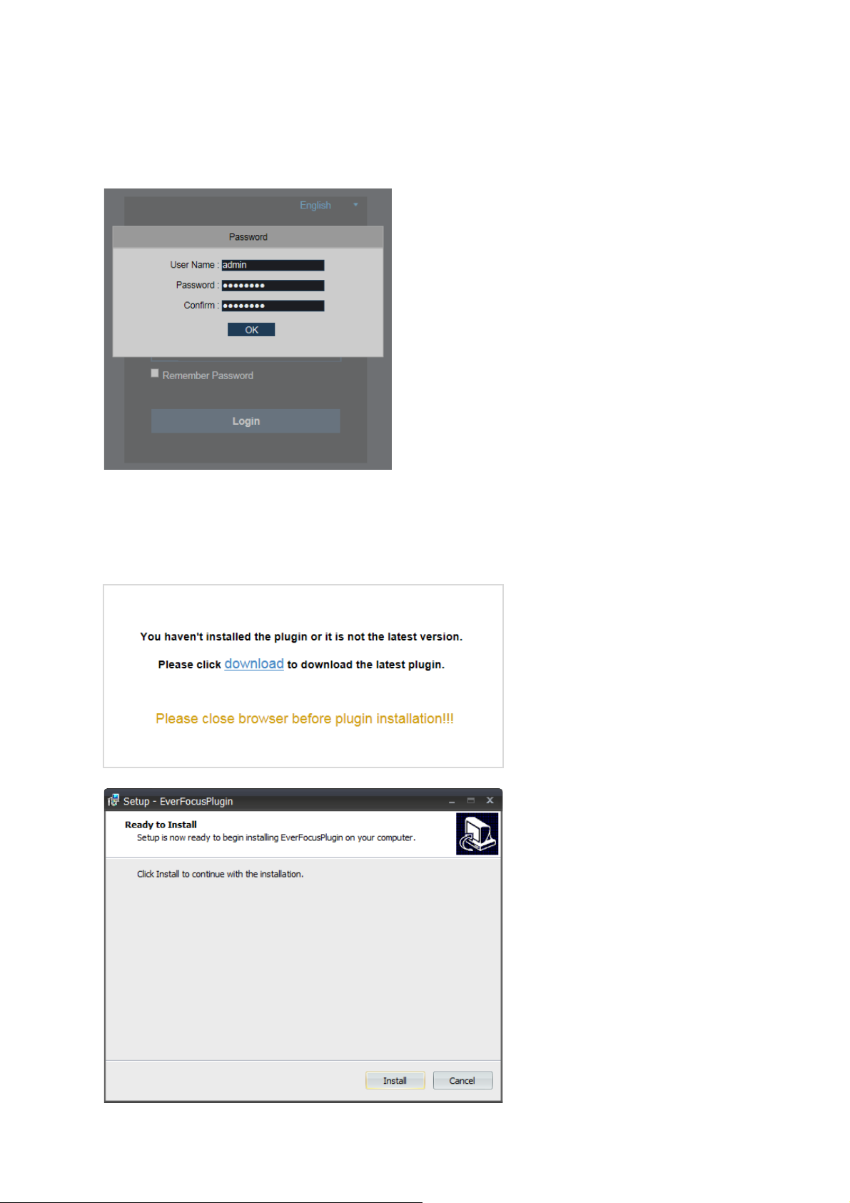
3. To access the Live View window, double click the IP address in the IP Address column, the Password
window pops up. By default, the ID is admin and there is no password. Please input a password for the
first-time login. Click the OK button, the Login window appears. Input the password and then click
Login, the Live View window appears.
Note for the first time login:
When the Plug-in block appears on the browser, click download to install the plug-in. Reload the
webpage and you should see the live view page now.
11
Page 18

Value IP Series Network Cameras – H265, 2MP / 5MP / 8MP
4.2 Settings for Microsoft Internet Explorer
If you have difficulties viewing live view or upgrading firmware, it is suggested to complete the following
settings of your computer.
1. If your PC or laptop is running with Windows, it’s required to run the browser as administrator when
first entering the camera live view. Go to C:\Program Files (x86)\Internet Explorer, right-click the
browser and then click Run as administrator.
2. You may need to turn off the firewall and turn User Account Control off if you still can’t see the
camera Live View.
To turn User Account Control off, on the computer, click Start > Control Panel > System and
Security > Action Center (click Change User Account Control Settings), the User Account Control
Settings window appears. Adjust the slide bar to Never Notify and then click OK. Restart your
computer if requested.
12
Page 19

Value IP Series Network Cameras – H265, 2MP / 5MP / 8MP
High-speed modem
Internet
Straight-through LAN patch cable
Router
Cat 5 Straight Through Cable
Left: Pinout of a straight-through cable.
Cat 5
Right: Pinout of a crossed-over cable.
4.3 Connecting the Camera to the Network
There are three methods to connect the IP camera to the network: Router or LAN Connection,
One-to-One Connection and Direct High-Speed Connection.
Router or LAN connection
This is the most common connection in which the IP camera is connected to a router and allows multiple
users on and off site to see the IP camera on a LAN / WAN (Internet). The camera must be assigned an IP
address that is compatible with its LAN. By setting up port forwarding on the router, you can remotely
access the cameras from outside of the LAN via the Internet.
One-to-One Connection (Directly from PC to IP Camera)
You can connect directly without using a switch, router or modem. However, only the PC connected to
the camera will be able to view the IP camera. You will also have to manually assign a compatible IP
address to both the computer and the IP camera. Unless the PC has another network connection, the IP
camera will be the only network device visible to the PC. See the diagram below:
13
Page 20

Value IP Series Network Cameras – H265, 2MP / 5MP / 8MP
Cat 5
Straight Through Cable
High-speed modem
Internet
Direct High-Speed Connection
In a Direct High-Speed Connection, the camera connects directly to a modem without the need for a
router. You need to set the static or dynamic WAN IP address assigned by your ISP (Internet Service
Provider) in the camera’s configuration web pages. To access the camera, just type
“http://xxx.xxx.xxx.xxx”, where xxx.xxx.xxx.xxx is the IP address given by your ISP. If you have a dynamic
IP address, this connection may require that you use DDNS for a reliable connection.
14
Page 21
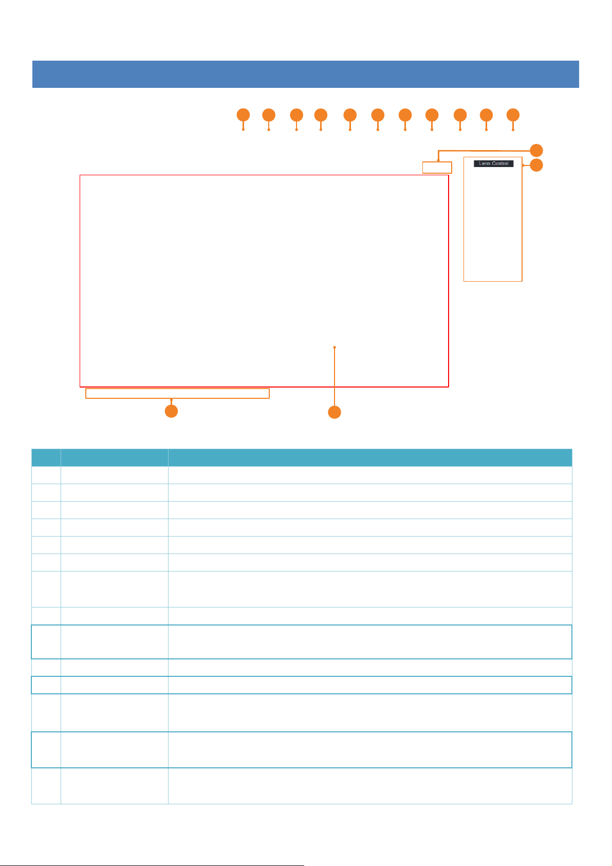
Value IP Series Network Cameras – H265, 2MP / 5MP / 8MP
1
2 3 4 5 6 7 8 9
10
11
12
12
13
14
Displays the IP camera live view. You can double click on the Live View window
5 Live View Window
No. Name Description
1 Live Click to display the Live View window.
2 Playback Click to enter the Playback page. Please refer to 5.1 Playback.
3 Display Click to enter the Display setting page. Please refer to 5.2 Display Setting.
4 Record Click to enter the Record setting page. Please refer to 5.3 Record.
5 Alarm Click to enter the Alarm setting page. Please refer to 5.4 Alarm Setting.
6 Network Click to enter the Network setting page. Please refer to 5.5 Network Setting.
7 Storage
Click to enter the Storage Device setting page. Please refer to 5.6 Storage
Setting.
8 System Click to enter the System setting page. Please refer to 5.7 System Setting.
9 Intelligent
Click to enter the Intelligent setting page. Please refer to 5.8 Intelligent
Setting.
10 Login Info Move the mouse cursor over this icon to display the Login information.
11 Logout Click to logout the IP camera.
Color Setting /
12
Lens Control
Click the buttons to display the setup panel. Please refer to 5.9 Color Setting
and 5.10 Lens Control.
Live View Function
13
Icons
14 Live View Window
You can perform some functions on the Live View using these icons. Please
refer to 5.11 Live View Function Icons.
to full screen. Double click on the Live View can exit full screen.
15
Page 22

Value IP Series Network Cameras – H265, 2MP / 5MP / 8MP
5.1 Playback
Click the Playback button on the top navigation bar. The Playback window displays. You can play back the
recordings stored in the on-camera micro SD card.
To st ar t playing back:
1. Select the date on the calendar (the date with an orange bar on the bottom indicates there are recordings
on the date).
2. Select the desired recording type(s) from the Search Type drop-down list.
3. Click the Search button, the recordings will be displayed on the time bar in different colors.
Green: Normal recordings; Yellow: Motion recordings; Blue: Intelligent recordings; Red: IO; Purple: Sound
Detection recordings.
4. Click the Play button to start playing back.
16
Page 23
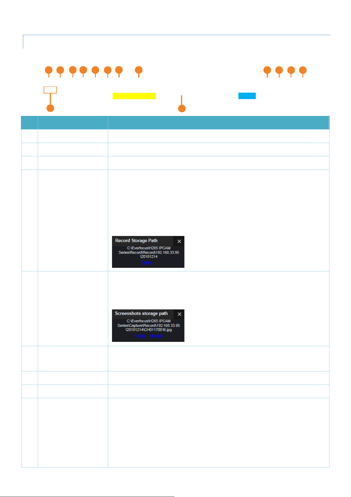
Value IP Series Network Cameras – H265, 2MP / 5MP / 8MP
00:00 02:00 06:00 08:00 10:00 12:00 14:00 16:
00 18:00 20:00 22:00 24:00
1
2
3
4
5
6
7
8
9
10
11 12
13
14
Click to take a snapshot, a message window appears on the bottom-left
5.1.1 Playback Panel
You can use the Playback Panel to operate the below functions:
No. Name Description
1 Play/Pause Click to Play or Pause playing back.
2 Stop Click to Stop playing back.
3 Step Forward Click the button to play the recording frame by frame.
During the playback process, you can click the Video Clips button to start
recording from the clicked time, click the button again to stop recording, a
message window appears on the bottom-left corner of the screen. Click
Folder to open the folder to find the recording file. To change the manual
record storage path or the file format, please refer to 5.7.7 Local Settings.
4 Video Clips
You can use EverFocus Player or any player supporting the video format to
play back the recordings. EverFocus Player is included in the Software CD.
corner of the screen. Click Folder to open the folder to find the snapshot
image. Or click Preview to preview the snapshot image. To change the
storage path or image format, please refer to 5.7.7 Local Settings.
5 Snapshot
Click to download recordings. To perform the Download function, please
6 Download
refer to 5.1.2 Download.
7 Speed Click to select a playback speed.
8 Audio Click to switch on/off the speaker. You can also adjust the volume.
Click to enable the Digital Zoom mode. To exit the Digital Zoom mode, click
the button again. To perform the Digital Zoom function:
a. Click the Digital Zoom button to enable the function.
9 Digital Zoom
b. Use your mouse to draw an area where you want to have a close-up
view on the stream. The area will be zoom-in.
c. Right-click to exit the Digital Zoom mode.
17
Page 24

Value IP Series Network Cameras – H265, 2MP / 5MP / 8MP
Click to display the Playback window in full screen mode. To exit full screen
10 Original Aspect Ratio Click to play back all the streams with original aspect ratio.
11 Stretch Click to stretch all the streams on the Playback window.
12 Full Screen
mode, press the ESC button on the keyboard or double-click on the screen.
13 Time Span Buttons You can adjust the time span on the Time Bar by clicking the buttons.
Single-click on the time bar at a certain time will start playing back from
the clicked time. The colors on the time bar represent different recording
14 Time Bar
types. Green: Normal recordings; Yellow : Motion recordings; Blue:
Intelligent recordings; Red: IO; Purple: Sound Detection recordings.
5.1.2 Download
You can download the recordings on the Playback window.
1. Click the Download button, the corresponding recordings will be displayed.
2. Select the desired recordings you want to download, and then click Start Download. To change the storage
path or the file format, please refer to 5.7.7 Local Settings.
18
Page 25

Value IP Series Network Cameras – H265, 2MP / 5MP / 8MP
5.2 Display Setting
Click the Display button on the top navigation bar to enter the Display Setting page.
5.2.1 Live
You can configure the live display settings on this page.
Name: Input a camera name. Alphabetic, numeric and Chinese characters are supported.
Signal Format: Select a signal format from 60Hz or 50Hz.
Transparency: Adjust the transparency of the text (time or camera name) overlay displayed on the stream.
Show Name: Switch the button to the right to enable displaying camera name on the stream.
Show Time: Switch the button to the right to enable displaying system time on the stream.
Click Refresh to refresh the page; click Apply to save the settings.
19
Page 26

Value IP Series Network Cameras – H265, 2MP / 5MP / 8MP
5.2.2 Image
You can configure the image settings on this page.
Day/Night Mode: Select a Day/Night mode for the camera to display the color or B/W images.
• Auto: Select Auto for the camera to automatically switch to day or night mode. You can further set up a
Delay Switch time (second) in the below field.
• Color Mode: Select Color Mode for the camera to display color images.
• Black White Mode: Select Black White Mode for the camera to display B/W images.
• Schedule (B/W): Select Schedule (B/W) for the camera to display B/W images during the setup time range.
Please select the Start Time and End Time in the below field.
Delay Switch (s): This function can only be activated if you select Auto for the Day/Night Mode. Set up a delay
switch time (seconds) for the camera to auto switch between day and night modes.
IR-LED: Select On to turn on IR LEDs; select Off to turn off IR-LED; select Auto for the camera to automatically
turn on / off the IR-LED based on the light sensor on the IP camera.
Flip: Switch the button to the right to enable the Flip function. The image will be rotated vertically around a
horizontal axis.
Mirror: Switch the button to the right to enable the Mirror function. The image will be rotated horizontally
around a vertical axis.
Hallway Mode: Switch the button to the right to enable the Hallway Mode function. This function allows users
to monitor vertically-oriented areas such as hallway, corridors and aisles. Please refer to 5.2.2.1 Hallway Display
for more details.
20
Page 27

Value IP Series Network Cameras – H265, 2MP / 5MP / 8MP
Rotate: Select 0 to rotate the camera view by 0 degree; select 180 to rotate the camera view by 180 degree.
BLC: Switch the button to the right to enable the BLC (Backlight Compensation) function.
BLC Level: Adjust the level for the BLC function.
BLC Area: Select an area to apply the BLC function.
3D Noise Reduction: Select Auto to
• Auto: Select Auto for the camera to automatically turn on the 3DNR function.
• Manual: Select to turn on the 3DNR function based on the setup Level.
• Disable: Select to disable the 3DNR function.
DWDR: Switch the button to the right to enable the DWDR function and then you will have to adjust a Level for
the DWDR function.
AGC: If you select Manual in the Shutter field, set up the AGC for the camera. The lower the AGC level, the
lower the video signal and the noise.
White Balance:
• Auto: Select for the camera to automatically adjust the white balance.
• Manual: Select to adjust the Red, Green, Blue values yourself.
• Indoor: Select Indoor if your camera is installed in an indoor environment.
Shutter:
• Auto: Select for the camera to automatically adjust the Shutter.
• Manual: Select to manually adjust the shutter speed. Select a speed in the Time Exposure field. Also set
up the AGC in the AGC field above.
Time Exposure: If you select Auto in the Shutter field, the camera will automatically apply a max. shutter speed.
If you select Manual in the Shutter field, select a shutter speed from the drop-down list.
Defog Mode:
• Auto: Select Auto for the camera to automatically turn on the Defog function.
• Manual: Select to turn on the Defog function based on the setup Level.
• Disable: Select to disable the Defog function.
Click Refresh to refresh the page; click Apply to save the settings; click Default to restore to the default settings.
21
Page 28

Value IP Series Network Cameras – H265, 2MP / 5MP / 8MP
90°
90°
Rotate Screws
(both sides)
90°
90°
5.2.2.1 Hallway Display
Hallway Display (9:16) allows users to monitor vertically-oriented areas such as hallway, corridors and aisles.
To achieve the best 9:16 display effect, it is recommended to:
1. Rotate the camera sideways by 90°:
For EHN Series:
Rotate the camera to the left or right by 90°.
2. Go to Display > Image and enable the Hallway Mode.
For EZN Series:
Loosen the Rotate Screws on both sides and rotate the
camera to the left or right by 90°.
3. On the Live View, click the Original Ratio / Hallway button to display the streams in Hallway mode (9:16).
22
Page 29

Value IP Series Network Cameras – H265, 2MP / 5MP / 8MP
5.2.3 Privacy Mask
You can configure the Privacy Mask settings on this page. The Privacy Mask can block out sensitive areas from
view, covering the areas in both Live View and Recordings. This feature is useful when users don’t want the
sensitive information visible. Up to four Privacy Masks can be configured.
To set up Privacy Mask:
1. Switch the Privacy Mask button to the right to enable the function.
2. On the preview window, draw a rectangle area (red color) to apply with the privacy mask. Up to four areas
can be configured.
3. To delete an area, click on an area, the selected area will be highlighted with a yellow frame. Click the Delete
button to delete the selected area.
4. After configuring the privacy mask areas, click the Apply button to apply the settings.
Click Refresh to refresh the page; click Apply to save the settings.
23
Page 30

Value IP Series Network Cameras – H265, 2MP / 5MP / 8MP
5.2.4 Audio
You can configure the audio settings on this page.
Enable Audio: Switch the button to the right to enable audio configuration.
Note: If you want to enable the Audio function, after configuring the Audio configuration on this page,
please turn on the Audio function on the Video Streaming page (please refer to 5.5.2 Video Streaming).
Output Volume: Select an audio output volume (0~10).
Input Volume: Select an audio input volume (0~10).
Audio Type: Select an audio codec.
Click Refresh to refresh the page; click Apply to save the settings.
24
Page 31

Value IP Series Network Cameras – H265, 2MP / 5MP / 8MP
5.2.5 ROI
You can configure the ROI settings on this page.
Bitrate: Select a stream type to be applied with the ROI bitrate.
ROI ID: Up to 8 ROI areas can be configured for each stream type.
Enable ROI: Select Enable to enable the configured ROI area(s).
ROI Level: Select an ROI level for each area. The higher the level, the better the image quality in ROI area.
Non-ROI FPS (1-24): Select a FPS to be applied to the non-ROI areas. Lower FPS can not only reduce the
bandwidth, but also increase the recording time to the on-camera SD card.
Click Refresh to refresh the page; click Apply to save the settings.
To set up ROI:
1. Set up the configurations including Bitrate, ROI ID, Enable ROI, ROI Level and FPS for the Non-ROI FPS.
2. On the preview window, draw a rectangle area (red color) to apply with the ROI. You can only configure 1
ROI area for each ROI ID. Up to 8 ROI ID can be configured.
3. To de le te the ROI area, click the Clear button.
4. Click the Apply button to apply the settings.
25
Page 32

Value IP Series Network Cameras – H265, 2MP / 5MP / 8MP
5.3 Record
5.3.1 Record Setting
You can configure the record settings on this page. Please note that to enable the record function, a micro SD
card has to be inserted to the IP camera in advance. Please also format the micro SD card for the first-time use
(refer to 5.6.1 Storage).
Stream Mode: Select a recording stream mode.
Record: Switch the button to the right to enable the record function. Please note that to enable the record
function, a micro SD card has to be inserted to the IP camera in advance. Please also format the micro SD card
for the first-time use (refer to 5.6.1 Storage).
Pre-Record: Switch the button to the right to enable the pre-record function for all the alarm recordings. The
camera will start recording 10 seconds before the alarms o ccu r.
Network Failed: Switch the button to the right to enable the network failed function. When the network is
disconnecting, the IP camera will start recording until the network connection is back to normal.
Click Refresh to refresh the page; click Apply to save the settings.
Note:
1. To configure the recording storage path, please refer to 5.7.7 Local Settings.
2. After setting up the Record settings, you can optionally set up the Record Schedule, please refer to 5.3.2
Record Schedule.
26
Page 33

Value IP Series Network Cameras – H265, 2MP / 5MP / 8MP
5.3.2 Record Schedule
After setting up the Record settings, you can configure the record schedule on this page.
Normal: Move your mouse cursor over the schedule time blocks. The first line of the time block on each day is
the Normal time blocks. Click and drag on the schedule time blocks to draw the blocks with green color, which
will be applied with normal recording function.
Motion: Move your mouse cursor over the schedule time blocks. The second line of the time block on each day
is the Motion time blocks. Click and drag on the schedule time blocks to draw the blocks with yellow color,
which will be applied with motion recording function. Note that for this function to work, you will have to
configure the motion settings in advance (please refer to 5.4.1 Motion).
IO: Move your mouse cursor over the schedule time blocks. The third line of the time block on each day is the
IO time blocks. Click and drag on the schedule time blocks to draw the blocks with red color, which will be
applied with IO recording function. Note that for this function to work, you will have to configure the IO settings
in advance (please refer to 5.4.2 I/O).
Sound Detection: Move your mouse cursor over the schedule time blocks. The fourth line of the time block on
each day is the Sound Detection time blocks. Click and drag on the schedule time blocks to draw the blocks with
purple color, which will be applied with Sound Detection recording function. Note that for this function to work,
you will have to configure the Sound Detection settings in advance (please refer to 5.4.4 Sound Detection).
Click Refresh to refresh the page; click Apply to save the settings; click Default to restore to the default settings.
27
Page 34

Value IP Series Network Cameras – H265, 2MP / 5MP / 8MP
5.4 Alarm Setting
5.4.1 Motion
You can configure the motion settings on this page.
Enable: Switch the button to the right to enable the Motion function.
Sensitivity: Select a sensitivity for the motion detection. The larger the value, the higher the sensitivity.
Alarm Out: Switch the button to the right to enable the alarm output, and then further configure the Timeout
Duration below.
Timeout Duration: After enabling the Alarm Out, select a timeout duration for the alarm output.
Post Recording: Select a post recording time when a motion event is triggered.
Send Email: Switch the button to the right to enable the Email alert function. When a motion event is triggered,
the camera will send an email alert with a snapshot image to the pre-configured Email receiver. Note that for
this function to work, you have to set up the Email function in advance (refer to 5.5.3 Email).
Send to Cloud: Switch the button to the right to enable the camera to automatically send the Motion alarm
snapshot images to the associated Dropbox. Note that for this function to work, you have to set up the Cloud
Storage function in advance (refer to 5.6.2 Cloud Storage).
Send to FTP: Switch the button to the right to enable the FTP function. When a motion event is triggered, the
camera will upload alarm images to FTP server. Note that for this function to work, you have to set up FTP in
advance, please refer to 5.5.7 FTP.
Enable Recording: Switch the button to the right to enable the motion recording function. Note that for Motion
recording function to work, the Record Schedule function has to be configured (please refer to 5.3.2 Record
Schedule).
Click Refresh to refresh the page; click Apply to save the settings.
28
Page 35

Value IP Series Network Cameras – H265, 2MP / 5MP / 8MP
5.4.2 I/O
After connecting the external I/O devices to the camera, you can configure the I/O settings on this page.
Alarm Type: Select an alarm type for the alarm input. Options include Normally-Open, Normally-Close and Off.
Timeout Duration: After enabling the Alarm Out, select a timeout duration for the alarm output.
Send Email: Switch the button to the right to enable the Email alert function. When an I/O alarm is triggered,
the camera will send an email alert with a snapshot image to the pre-configured Email receiver. Note that for
this function to work, you have to set up the Email function in advance (refer to 5.5.3 Email).
Alarm Out: Switch the button to the right to enable the alarm output, and then further configure the Timeout
Duration above.
Send to Cloud: Switch the button to the right to enable the camera to automatically send the I/O alarm
snapshot images to the associated Dropbox. Note that for this function to work, you have to set up the Cloud
Storage function in advance (refer to 5.6.2 Cloud Storage).
Send to FTP: Switch the button to the right to enable the FTP function. When an I/O alarm is triggered, the
camera will upload alarm images to FTP server. Note that for this function to work, you have to set up FTP in
advance, please refer to 5.5.7 FTP.
Enable Recording: Switch the button to the right to enable the I/O alarm recording function. Note that for /O
alarm recording to work, the Record Schedule function has to be configured (please refer to 5.3.2 Record
Schedule).
Post Recording: Select a post recording time when an I/O alarm is triggered.
Click Refresh to refresh the page; click Apply to save the settings.
29
Page 36

Value IP Series Network Cameras – H265, 2MP / 5MP / 8MP
5.4.3 Tamper Alarm
You can configure the tamper alarm settings on this page.
Enable: Switch the button to the right to enable the Tamper Alarm function.
Sensitivity: Select a sensitivity for the tamper detection. The larger the value, the higher the sensitivity.
Send Email: Switch the button to the right to enable the Email alert function. When a tamper alarm is triggered,
the camera will send an email alert with a snapshot image to the pre-configured Email receiver. Note that for
this function to work, you have to set up the Email function in advance (refer to 5.5.3 Email).
Alarm Out: Switch the button to the right to enable the alarm output, and then further configure the Timeout
Duration below.
Timeout Duration: After enabling the Alarm Out, select a timeout duration for the alarm output.
Click Refresh to refresh the page; click Apply to save the settings.
30
Page 37

Value IP Series Network Cameras – H265, 2MP / 5MP / 8MP
5.4.4 Sound Detection
You can configure the sound detection settings on this page. This function is only available for the supported IP
cameras. Please contact EverFocus for more details. ts@everfocus.com.tw
Enable: Switch the button to the right to enable the Sound Detection function. And then configure the Sound
Detection Schedule on the below schedule grids.
Rise: Switch the button to the right to enable the Sound Rise function.
Rise Sensitivity: Adjust the sensitivity for the sound rise detection.
Sound Intensity: Adjust the intensity for the sound rise detection.
Decline: Switch the button to the right to enable the Sound Decline function.
Decline Sensitivity: Adjust the sensitivity for the sound decline detection.
Send Email: Switch the button to the right to enable the Email alert function. When a sound detection event is
triggered, the camera will send an email alert with a snapshot image to the pre-configured Email receiver. Note
that for this function to work, you have to set up the Email function in advance (refer to 5.5.3 Email).
Sound Detection Schedule:
Move your mouse cursor over the schedule time blocks. Click and drag on the schedule time blocks to draw the
blocks with purple color, which will be applied with Sound Detection function.
Sound Detection Record Schedule:
If you want the camera to record the Sound Detection alarm, you will have to configure the record schedule for
the sound detection function (please refer to 5.3.2 Record Schedule).
Click Refresh to refresh the page; click Apply to save the settings.
31
Page 38

Value IP Series Network Cameras – H265, 2MP / 5MP / 8MP
5.5 Network Setting
5.5.1 Network
You can configure the network settings on this page.
Type: Select a network type.
• DHCP: This setting lets the system use an automatically assigned (dynamic) IP address. This address can
change under certain circumstances. For instance, when the camera’s network switch/hub has to be
rebooted. Do not assign to the DHCP server the same IP addresses used for the other network cameras
and PCs with unique IP addresses.
• PPPoE: This is a DSL-connection application. The ISP will ask the user to input a username and password.
Contact your ISP for these details.
• Static IP: The user can manually set the Static IP address. This type of address is stable and cannot change,
but the user has to make sure there are no address conflicts with other network-connected devices.
Client Port: The Client port can be used to send information through (e.g. using the mobile
app). If the default port 9988 is already taken by other applications, please change it.
IP Address: The IP address of the IP Camera. The IP address consists of four groups of numbers, separated by
periods. For example, “192.168.001.100”.
Subnet Mask: Subnet mask is a network parameter which defines a range of IP addresses that can be used on a
network. The subnet address also consists of four groups of numbers, separated by periods. For example,
“255.255.000.000”.
32
Page 39

Value IP Series Network Cameras – H265, 2MP / 5MP / 8MP
Gateway: This address allows the IP Camera to access the Internet. The format of the Gateway address is the
same as the IP Address. For example, “192.168.001.001”.
DNS: DNS1 is the primary DNS server and DNS2 is a backup DNS server. Usually, it’s enough to just enter the
DNS1 server address.
IPV6-IP Address: The IPV6 address of the IP Camera.
IPV6-Gateway: This address allows the IP Camera to access the Internet.
UPnP: If you want to remotely login the IP Camera using Web Client, you need to enable the UPnP function and
also enable the Port Forwarding function on your router.
Note:
1. For the UPnP function to work, an UPnP-enabled router is required.
2. If your router does not support UPnP, ensure the Port Forwarding function is manually enabled
on your router.
3. To enable UPnP, the Client port and HTTP port should be within 1024~65535.
P2P Switch: Check the box to enable the P2P function. If P2P function is enabled, a QR code will be displayed
on the System Info page (System > Info). You can scan the QR code with EverFocus eFVMS App installed on your
mobile device to add and remote access the IP Camera. Please refer to 5.7.9.1 Performing the P2P Function.
Click Refresh to refresh the page; click Apply to save the settings.
33
Page 40

Value IP Series Network Cameras – H265, 2MP / 5MP / 8MP
5.5.2 Video Streaming
You can configure the video streaming settings on this page.
You can configure the below configurations to Main Stream, Sub Stream and Mobile Stream.
Resolution: Select a resolution.
FPS: Select a frame rate per second for the selected stream type.
Video Type: Select a video codec.
Video Level: Select Main Profile for the video codec.
Bitrate Control: Select CBR (constant bitrate) if the scene is simple and less changing, such as a gray wall. Select
VBR (variable bitrate) if the scene is complex, such as a department store. If VBR is selected, select a video
quality from the drop-down list.
Bitrate Mode: Select User-defined to set up bitrate manually; or Pre-defined to auto-select bitrate.
Bitrate: The Bitrate corresponds to the speed of data transfer that the IP Camera will use to record video.
Recordings that are encoded at higher bitrates, will be of better quality.
Audio: Switch the button to the right to enable the audio function.
I-Frame Interval: Set up an I-Frame interval.
Click Refresh to refresh the page; click Apply to save the settings.
34
Page 41

Value IP Series Network Cameras – H265, 2MP / 5MP / 8MP
5.5.3 Email
You can configure the email settings on this page.
Email: Switch the button to the right to enable the Email function.
Encryption: Select an encryption if your Email server requires the SSL or TLS verification. Select Auto if you are
not sure. Select Disable to disable this function.
SMTP Port: Enter the port number used by the SMTP server.
SMTP Server: Enter the SMTP server address of your Email.
User Name: Input the user name of your Email account.
Password: Input the password of the sender.
Sender: Input the Email address of the sender.
Receiver1-3: Input the Email address of the receiver. You can input 3 receiver email addresses.
Interval: Configure an interval to send Emails when events occur.
Click Refresh to refresh the page; click Apply to save the settings; click Test Email to test the Email function;
click Cancel to cancel the settings.
35
Page 42

Value IP Series Network Cameras – H265, 2MP / 5MP / 8MP
5.5.4 DDNS
You can configure the DDNS setting on this page. DDNS (Dynamic Domain Name System) is a service used to
map a domain name to the dynamic IP address of a network device. You can set up the DDNS service for
remote access to the IP Camera.
DDNS assigns a domain name (URL) to the IP Camera, so that the user does not need to go through the trouble
of checking if the IP address assigned by DHCP Server has changed. Once the IP is changed, the IP Camera will
automatically update the information to the DDNS to ensure it is always available for remote access.
Note that before enabling the following DDNS function, user should have applied for a host name from the DDS
service provider’s website.
DDNS: Switch the button to the right to enable the DDNS function
Server: Select a DDNS service provider from the drop-down list. Note that before enabling the following DDNS
function, user should have applied for a host name from the DDS service provider’s website.
Hostname: Input the domain name obtained from the DDNS service provider.
Username: Input the user name of the DDNS account.
Password: Input the password of the DDNS account.
Click Refresh to refresh the page; click Apply to save the settings; click the Test DDNS button to test whether
the DDNS function is working normally.
36
Page 43

Value IP Series Network Cameras – H265, 2MP / 5MP / 8MP
5.5.5 IP Filter
You can configure the IP Filter settings on this page. This function allows you to allow or deny some specific IP
address to access the IP Camera. By default, all IP addresses are allowed to access the camera.
To set up IP filtering:
1. From the Filter Mode drop-down list, select a filter mode. You can only activate one mode for the IP camera:
• Allow all IP connections: Select this mode to allow all IP addresses to access the IP camera. Click the
Apply button to save the settings.
• Allow the checked IP connections only: Select this mode to allow only some specific IP addresses to
access the IP camera. Click the Add button to add the IP addresses and then check the Enable box. Click
the Apply button to save the settings.
• Deny the checked IP connections only: Select this mode to deny only some specific IP addresses to
access the IP camera. Click the Add button to add the IP addresses and then check the Enable box. Click
the Apply button to save the settings.
2. If you want to delete the IP addresses from the list, click on the column of the IP address, the column will be
highlighted with a blue background, and then click the Delete button.
37
Page 44

Value IP Series Network Cameras – H265, 2MP / 5MP / 8MP
5.5.6 RTSP
You can enable the RTSP function on this page.
RTSP Enable: Switch the button to the right to enable the RTSP function.
RTSP Port: The RTSP port allows the IP Camera to transmit real-time streaming to other devices (e.g. using a
streaming media player).
Anonymous Login: Switch the button to the right to enable this function.
RTSP Syntax:
rtsp://[IP Address]:[RTSP Port]/ch01/[A]
* IP Address: IP address of the IP Camera
* RTSP Port: The default RTSP port is 554, which can be changed between 1024 and 65535. Changing the RTSP
port will restart the IP camera.
* A: Stream Type: 0 (main stream), 1 (sub stream), 2 (mobile stream)
Example:
rtsp://192.168.31.33:554/ch01/0
Click Refresh to refresh the page; click Apply to save the settings.
38
Page 45

Value IP Series Network Cameras – H265, 2MP / 5MP / 8MP
5.5.7 FTP
You can configure the FTP settings on this page. When an alarm is triggered, the IP Camera will send an instant
snapshot image to the FTP.
FTP Enable: Switch the button to the right to enable the function.
Server: Input the FTP server IP.
Port: Keep the port 21.
Username: Input the user name of the FTP server.
Password: Input the password of the FTP server.
Send Images: Switch the button to the right to enable the function.
Click Refresh to refresh the page; click Apply to save the settings.
Note: For the FTP function to work, after configuring the FTP settings, you will have to enable the
Send to FTP function on the Motion (see 5.4.1 Motion) and I/O (see 5.4.2 I/O) alarm setup page.
39
Page 46

Value IP Series Network Cameras – H265, 2MP / 5MP / 8MP
5.5.8 SNMP
You can configure the SNMP settings on this page. Select a SNMP version and input the configurations. Click the
Apply button to apply the settings.
5.5.9 HTTPS
You can configure the HTTPS settings on this page. Switch the HTTPS button to the right to enable the function.
Select an HTTPS Type and then click the Apply button.
40
Page 47

Value IP Series Network Cameras – H265, 2MP / 5MP / 8MP
5.6 Storage Setting
5.6.1 Storage
You can configure the SD card storage on this page. After inserting an micro SD card to the card slot, the IP
camera will automatically detect the capacity of the on-camera SD card.
Overwrite: Select Auto to enable the overwrite function. If Auto is selected, the IP camera will overwrite the
oldest files on the SD card when SD card is full.
Format: Click to format the on-camera SD card. For the first time use SD card or a new SD card, users have to
format the SD card before use.
Click Refresh to refresh the page; click Apply to save the settings.
41
Page 48

Value IP Series Network Cameras – H265, 2MP / 5MP / 8MP
5.6.2 Cloud Storage
You can configure the cloud storage (Dropbox) settings on this page. After configuring the settings, the IP
camera will automatically send the alarm snapshot images to the associated Dropbox when alarm events occur.
To perform the Cloud function:
1. Register an account on Dropbox website. It’s recommended to create the account with the same Email
address and password used for your IP camera.
2. Ensure the IP camera network is working properly.
3. Configure the Email function (refer to 5.5.3 Email) of the IP camera.
4. Configure the Cloud settings on this page:
a. Switch the Cloud Storage button to the right to enable the Cloud function.
b. Input a name in the Driver Name field, which will be created on the Dropbox as a directory for restoring
the snapshot images from IP camera.
c. Click the Apply button.
5. Click the Activate Cloud button to activate the Cloud function.
a. After clicking the Activate Cloud button, the sign in page of Dropbox appears. Sign in the Dropbox, the
below page appears. Input the IP address of the IP camera and then click the Authorize button.
42
Page 49

Value IP Series Network Cameras – H265, 2MP / 5MP / 8MP
b. Input the username and password of the IP camera.
c. When this message appears, you are able to use the Cloud function.
Note: For the Cloud Storage function to work, after configuring the Cloud Storage settings, you will
have to enable the Send to Cloud function on the Motion (see 5.4.1 Motion) and I/O (see 5.4.2 I/O)
alarm setup page.
43
Page 50

Value IP Series Network Cameras – H265, 2MP / 5MP / 8MP
5.7 System Setting
5.7.1 General
You can configure the system general settings on this page.
System Time: Set up a system date and time.
Date Format: Select a format for the date.
Time Format: Select a format for the time.
【DST Setting】Select DST and then configure the below settings. The DST (Daylight Saving Time) function allows
you to select the amount of time that Daylight Saving has increased by in your particular time zone or region.
Daylight Saving Time: Switch the button to the right to enable the DST function.
DST Mode: Select Week or Date to configure the start/end time below.
Week: Select a month, a particular day and time when Daylight Saving starts and ends. For example, 2am on
the first Sunday of a particular month.
Date: Select the start date (click the calendar icon), end date and time when Daylight Saving starts and ends.
Time Offset: Select the amount of time that Daylight Saving has increased by in your time zone. This refers to
the difference in minutes, between Coordinated Universal Time (UTC) and the local time.
Start Time: Select a start time for the DST to start.
44
Page 51

Value IP Series Network Cameras – H265, 2MP / 5MP / 8MP
End Time: Select an end time for the DST to stop.
【NTP Settings】Select NTP and then configure the below settings. The NTP (Network Time Protocol) function
allows your IP camera to automatically sync its clock with a time server. This gives it the ability to constantly
have an accurate time setting (your IP camera will periodically sync automatically).
Enable NTP: Switch the button to the right to enable the NTP function. When NTP function is enabled, the
system will calibrate the system time at 00:07:50 daily and every time when the system is started up.
Server Address: Select a NTP server.
Time Zone: Select a time zone of your region.
【Synchronize】Select Synchronize to synchronize the time with your PC.
Click Refresh to refresh the page; click Apply to save the settings.
45
Page 52

Value IP Series Network Cameras – H265, 2MP / 5MP / 8MP
5.7.2 User Account
You can configure the user account settings on this page. Up to 7 user accounts (1 administrator and 6 users)
can be configured.
To edit the user privileges:
1. Select a user from the list by clicking on it, the below privilege options appears.
2. Check the boxes to grant functions for the selected user account. After the configuration, click Apply to
save the settings.
Parameter: Allow users to set all the parameter settings.
Live: Allow users to access the Live View.
Playback: Allow users to access and operate the Playback function.
PTZ Control: Allow users to operate the PTZ control function.
RTSP: Allow users to operate the RTSP function.
46
Page 53

Value IP Series Network Cameras – H265, 2MP / 5MP / 8MP
3. You can configure the user name/password in the right-side field. In the Active field, switch to the right to
enable the user account. At the bottom Password field, switch to enable the password (if Disable is
selected, the user can login without password).
4. Click Apply to save the settings.
Note: The Administrator account has full privileges so the functions cannot be configured.
47
Page 54

Value IP Series Network Cameras – H265, 2MP / 5MP / 8MP
5.7.3 Firmware Upgrade
You can upgrade IP camera firmware on this page. Click the Browse button to select the firmware file from the
computer. Click the Start button to start upgrading IP camera.
5.7.4 Load Default
You can load system default settings on this page. Select the desired items to be restored to factory default and
then click Apply. Restoring default settings will not delete recordings and snapshots saved to the on-camera SD
card.
48
Page 55

Value IP Series Network Cameras – H265, 2MP / 5MP / 8MP
5.7.5 System Reboot
This menu allows the IP camera to auto reboot regularly. It is recommended to leave this function enabled, as it
maintains the operational integrity of your IP camera.
Switch the Reboot Schedule button to the right to enable the function. Set up the reboot time for the IP
camera to regularly reboot at the setup time. Click the Apply button to save the settings.
Click Refresh to refresh the page; click Apply to save the settings; click Reboot to reboot the IP camera.
5.7.6 Import and Export
You can import or export system configurations on this page.
Import File: Click the Browse button to browse the file and then click the Import button.
Export Path: Click the Browse button to select a directory of your computer and then click the Export button.
49
Page 56

Value IP Series Network Cameras – H265, 2MP / 5MP / 8MP
5.7.7 Local Settings
You can configure the local storage path on this page.
Record Path: Select a storage path for recordings.
Download Path: Select a storage path for download recordings.
Snapshot Path: Select a storage path for snapshot images.
Recording Format: Select a recording file format.
Interval: Set up an interval (recording length) for general recordings.
Snapshot Format: Select a snapshot image format.
Click Apply to save the settings.
50
Page 57

Value IP Series Network Cameras – H265, 2MP / 5MP / 8MP
5.7.8 Log
You can view log information on this page. Select the log types, start time, end time, and then click the Search
button, the searched logs will be displayed on the list below.
51
Page 58

Value IP Series Network Cameras – H265, 2MP / 5MP / 8MP
EverFocus eFVMS
eFVMS by EverFocus
5.7.9 Info
You can view system info on this page.
If P2P function has been enabled, a QR code will be displayed on the Info page. You can scan the QR code with
EverFocus eFVMS App installed on your mobile device to add and remote access the IP camera. To enable the
P2P function, please refer to P2P Switch in 5.5.1 Network.
5.7.9.1 Performing the P2P Function
1. Install EverFocus eFVMS App. For Android users, go to Google Play Store. For iOS users, go to Apple
Store. After the installation process is complete, start eFVMS App.
52
Page 59

Value IP Series Network Cameras – H265, 2MP / 5MP / 8MP
9988
2. To add an IP camera through P2P, tap Menu > Device List, and then tap the “+” button on the
upper-right corner.
3. Scan the IP camera’s QR code on the info page of the IP Camera Web interface. Input the IP camera
password and Media Port 9988. Tap the Save button.
53
Page 60

Value IP Series Network Cameras – H265, 2MP / 5MP / 8MP
EZN1250: Channel01[P2P]
4. The IP camera is now added and connected to the App. You can start accessing the IP camera.
54
Page 61

Value IP Series Network Cameras – H265, 2MP / 5MP / 8MP
Analysis
5.8 Intelligent Setting
5.8.1 Record Schedule
You can configure record schedule for intelligent detection on this page. In order to active the intelligent
recording function, you need to configure the schedule recording for intelligent detection events. The schedule
will be activated 24 hours a day, 7 days a week.
1. Move your mouse cursor over the schedule time blocks.
2. Click and drag on the schedule time blocks to draw the blocks with blue color, which will be applied with
intelligent event recording function. To deselect the blocks, click and drag on the blue blocks to select again.
3. Click Apply to save the settings.
55
Page 62

Value IP Series Network Cameras – H265, 2MP / 5MP / 8MP
Analysis
Pedestrian Detection Face Detection Cross Counting
Line-Crossing Object Detection
Perimeter Intrusion
5.8.2 Detection
You can configure intelligent detection on this page. The intelligent detection functions include Perimeter
Intrusion Detection, Line Crossing Detection, Object Detection, Pedestrian Detection, Face Detection and Cross
Counting.
For 5MP and 8MP models, all intelligent detection functions are available. For 2MP models, only Perimeter
Intrusion Detection, Line Crossing Detection and Object Detection functions are supported.
5.8.2.1 Perimeter Intrusion Detection
When objects (people, vehicle or other objects) enter in or out of a pre-defined region, the Perimeter Intrusion
Detection event will be triggered. You can configure some event actions like event recording, alarm output or
Email alert when an event is triggered.
Switch: Switch the button to the right to enable the function.
Timeout Duration: After enabling the Alarm Out, select a timeout duration for the alarm output.
Post Recording: Select a post recording time when a Perimeter Intrusion event is triggered.
Sensitivity: Select a sensitivity for the Perimeter Intrusion Detection. The larger the value, the higher the
sensitivity.
Scene: Select Indoor or Outdoor based on the location where your IP camera is installed.
Alarm Out: Switch the button to the right to enable the alarm output, and then further configure the Timeout
Duration above.
56
Page 63

Value IP Series Network Cameras – H265, 2MP / 5MP / 8MP
1
Send Email: Switch the button to the right to enable the Email alert function. When a Perimeter Intrusion event
is triggered, the camera will send an email alert with a snapshot image to the pre-configured Email receiver.
Note that for this function to work, you have to set up the Email function in advance (refer to 5.5.3 Email).
Rule Number: Select a number to configure the areas. Up to 4 areas can be configured.
Rule Switch: Switch the button to the right to enable the Rule Type setup below.
Rule Type: Select a rule type.
Enable Recording: Switch the button to the right to enable the Perimeter Intrusion Detection recording
function. Note that for Perimeter Intrusion Detection recording function to work, the Record Schedule function
has to be configured (please refer to 5.8.1 Record Schedule).
Click Refresh to refresh the page; click Apply to save the settings.
To configure the Perimeter Intrusion Detection function:
1. Select 1 from the Rule Number drop-down list to configure the first area. Up to 4 areas can be configured.
2. Enable the Rule Switch and then define a Rule Type:
AB: Detects movement from A to B.
BA: Detects movement from B to A.
AB: Detects both movements from A to B and from B to A.
3. To draw an area:
a. Use your mouse to click 4 points to draw a rectangle shape. The shape should be convex. Concave
shape is not allowed.
b. If you want to move the area to other position or re-size the area, select the area by checking the red
box on the upper-left corner of the area, the borders of the area will change to red color. Drag and
drop the area to a desired position. Drag the red dots at the edge of the area can re-size the area.
c. Click the Apply button to save the settings.
d. You can follow the steps above to configure more areas. Up to 4 areas can be configured.
e. You can click the Clean All button to remove all the areas. To remove a certain area, select the area
by checking the red box on the upper-left corner of the area, and then click the Clear button.
Note: The configured areas should not be too narrow or small in order to enhance the
detection rate.
57
Page 64

Value IP Series Network Cameras – H265, 2MP / 5MP / 8MP
Pedestrian Detection Face Detection Cross Counting
Object Detection
Perimeter Intrusion Line-Crossing
Analysis
5.8.2.2 Line-Crossing Detection
When objects (people, vehicle or other objects) cross a pre-defined line, the Line-Crossing Detection event will
be triggered. You can configure some event actions like event recording, alarm output or Email alert when an
event is triggered.
Switch: Switch the button to the right to enable the function.
Timeout Duration: After enabling the Alarm Out, select a timeout duration for the alarm output.
Post Recording: Select a post recording time when a Line-Crossing event is triggered.
Sensitivity: Select a sensitivity for the Line-Crossing Detection. The larger the value, the higher the sensitivity.
Scene: Select Indoor or Outdoor based on the location where your IP camera is installed.
Alarm Out: Switch the button to the right to enable the alarm output, and then further configure the Timeout
Duration above.
Send Email: Switch the button to the right to enable the Email alert function. When a Line-Crossing event is
triggered, the camera will send an email alert with a snapshot image to the pre-configured Email receiver. Note
that for this function to work, you have to set up the Email function in advance (refer to 5.5.3 Email).
Rule Number: Select a number to configure the areas. Up to 4 areas can be configured.
Rule Switch: Switch the button to the right to enable the Rule Type setup below.
Rule Type: Select a rule type.
Enable Recording: Switch the button to the right to enable the Line-Crossing Detection recording function. Note
that for Line-Crossing Detection recording function to work, the Record Schedule function has to be configured
(please refer to 5.8.1 Record Schedule).
Click Refresh to refresh the page; click Apply to save the settings.
58
Page 65

Value IP Series Network Cameras – H265, 2MP / 5MP / 8MP
1
To configure the Line-Crossing Detection function:
1. Select 1 from the Rule Number drop-down list to configure the first line. Up to 4 lines can be configured.
2. Enable the Rule Switch and then define a Rule Type:
AB: Detects movement from A to B.
BA: Detects movement from B to A.
AB: Detects both movements from A to B and from B to A.
3. To dra w a line:
a. Use your mouse to click 2 points to draw a line.
b. If you want to move the line to other position or re-draw the line, select the line by checking the red
box on the upper-side of the line, the line will change to red color. Drag and drop the line to a desired
position. Drag the red dots of the line can re-size the line.
c. Click the Apply button to save the settings.
d. You can follow the steps above to configure more lines. Up to 4 lines can be configured.
e. You can click the Clean All button to remove all the lines. To remove a certain line, select the line by
checking the red box on the upper-left corner of the line, and then click the Clear button.
Note: The configured lines should not be too short in order to enhance the detection rate.
59
Page 66

Value IP Series Network Cameras – H265, 2MP / 5MP / 8MP
Pedestrian Detection Face Detection Cross Counting
Perimeter Intrusion Line-Crossing Object Detection
Analysis
5.8.2.3 Object Detection
When IP Camera detects missing objects and foreign objects in a pre-defined area, the Foreign/Missing Object
Detection event will be triggered. You can configure some event actions like event recording, alarm output or
Email alert when an event is triggered.
Switch: Switch the button to the right to enable the function.
Timeout Duration: After enabling the Alarm Out, select a timeout duration for the alarm output.
Post Recording: Select a post recording time when a Foreign/Missing Object event is triggered.
Sensitivity: Select a sensitivity for the Foreign/Missing Object Detection. The larger the value, the higher the
sensitivity.
Scene: Select Indoor or Outdoor based on the location where your IP camera is installed.
Alarm Out: Switch the button to the right to enable the alarm output, and then further configure the Timeout
Duration above.
Send Email: Switch the button to the right to enable the Email alert function. When a Foreign/Missing Object
event is triggered, the camera will send an email alert with a snapshot image to the pre-configured Email
receiver. Note that for this function to work, you have to set up the Email function in advance (refer to 5.5.3
Email).
Rule Number: Select a number to configure the areas. Up to 4 areas can be configured.
Rule Switch: Switch the button to the right to enable the Rule Type setup below.
Rule Type: Select a rule type.
Enable Recording: Switch the button to the right to enable the Foreign/Missing Object Detection recording
function. Note that for Foreign/Missing Object Detection recording function to work, the Record Schedule
function has to be configured (please refer to 5.8.1 Record Schedule).
Click Refresh to refresh the page; click Apply to save the settings.
60
Page 67

Value IP Series Network Cameras – H265, 2MP / 5MP / 8MP
1: Foreign & Missing
To configure the Foreign/Missing Object Detection function:
1. Select 1 from the Rule Number drop-down list to configure the first area. Up to 4 areas can be configured.
2. Enable the Rule Switch and then define a Rule Type:
Foreign: Detects Foreign objects only.
Missing: Detects Missing objects only.
Foreign & Missing: Detects both Foreign and Missing objects.
3. To draw an area:
a. Use your mouse to click 4 points to draw a rectangle shape. The shape should be convex. Concave
shape is not allowed.
b. If you want to move the area to other position or re-size the area, select the area by checking the red
box on the upper-left corner of the area, the borders of the area will change to red color. Drag and
drop the area to a desired position. Drag the red dots at the edge of the area can re-size the area.
c. Click the Apply button to save the settings.
d. You can follow the steps above to configure more areas. Up to 4 areas can be configured.
e. You can click the Clean All button to remove all the areas. To remove a certain area, select the area
by checking the red box on the upper-left corner of the area, and then click the Clear button.
Note: The configured areas should not be too narrow or small in order to enhance the
detection rate.
61
Page 68

Value IP Series Network Cameras – H265, 2MP / 5MP / 8MP
Face Detection Cross Counting
Perimeter Intrusion Line-Crossing Object Detection
Pedestrian Detection
Analysis
Level
Middle
Normal
Pedestrian Detection
5.8.2.4 Pedestrian Detection
Only 5MP and 8MP models support this function. When IP Camera detects pedestrian in a pre-defined area,
the Pedestrian Detection event will be triggered. You can configure some event actions like event recording,
alarm output or Email alert when an event is triggered.
Switch: Switch the button to the right to enable the function.
Timeout Duration: After enabling the Alarm Out, select a timeout duration for the alarm output.
Post Recording: Select a post recording time when a Pedestrian Detection event is triggered.
Level: Select a detection level for the Pedestrian Detection. The value stands for the distance of the objects.
Smaller value is suitable to detect objects that are far away from the camera. Larger value is suitable to detect
objects near the camera. The red squares on the top left corner represent the max. and min. object size of the
selected Level.
Scene: Select Indoor or Outdoor based on the location where your IP camera is installed.
Alarm Out: Switch the button to the right to enable the alarm output, and then further configure the Timeout
Duration above.
Send Email: Switch the button to the right to enable the Email alert function. When a Pedestrian Detection
event is triggered, the camera will send an email alert with a snapshot image to the pre-configured Email
receiver. Note that for this function to work, you have to set up the Email function in advance (refer to 5.5.3
Email).
Rule Number: Select a number to configure the areas.
Rule Switch: Switch the button to the right to enable the Rule Type setup below.
Rule Type: Select a rule type.
Enable Recording: Switch the button to the right to enable the Pedestrian Detection recording function. Note
that for Pedestrian Detection recording function to work, the Record Schedule function has to be configured
(please refer to 5.8.1 Record Schedule).
62
Page 69

Value IP Series Network Cameras – H265, 2MP / 5MP / 8MP
1: Foreign & Missing
Click Refresh to refresh the page; click Apply to save the settings.
To configure the Pedestrian Detection function:
1. Select 1 from the Rule Number drop-down list to configure the first area.
2. Enable the Rule Switch and then define a Rule Type.
3. To draw an area:
a. Use your mouse to click 4 points to draw a rectangle shape. The shape should be convex. Concave
shape is not allowed.
b. If you want to move the area to other position or re-size the area, select the area by checking the red
box on the upper-left corner of the area, the borders of the area will change to red color. Drag and
drop the area to a desired position. Drag the red dots at the edge of the area can re-size the area.
c. Click the Apply button to save the settings.
d. You can click the Clean All button to remove the area.
Note: The configured areas should not be too narrow or small in order to enhance the
detection rate.
63
Page 70

Value IP Series Network Cameras – H265, 2MP / 5MP / 8MP
Cross Counting
Perimeter Intrusion Line-Crossing Object Detection
Pedestrian Detection Face Detection
Analysis
Level
Middle
Normal
Face Detection
Snapshot Mode
Apply Mode
Advance
Roll Range
Pitch Range
Yaw Range
Picture Quality
Min Pixel
Real Time Mode
Recognition Mode
30
30
45
100
64
Rect
Rule Kind
(0-180)
(0-180)
(0-180)
(0-100)
(32-1080)
5.8.2.5 Face Detection
Only 5MP and 8MP models support this function. When IP Camera detects faces in a pre-defined area, the Face
Detection event will be triggered. You can configure some event actions like event recording, alarm output or
Email alert when an event is triggered.
Switch: Switch the button to the right to enable the function.
Timeout Duration: After enabling the Alarm Out, select a timeout duration for the alarm output.
Post Recording: Select a post recording time when a Face Detection event is triggered.
Alarm Out: Switch the button to the right to enable the alarm output, and then further configure the Timeout
Duration above.
Send Email: Switch the button to the right to enable the Email alert function. When a Face Detection event is
triggered, the camera will send an email alert with a snapshot image to the pre-configured Email receiver. Note
that for this function to work, you have to set up the Email function in advance (refer to 5.5.3 Email).
Snapshot Mode: Select a snapshot mode.
Apply Mode: Select a apply mode.
Advance: Switch the button to the right to enable the advanced functions including Roll Range, Pitch Range,
Yaw Range, Picture Quality and Min Pixel.
Rule Number: Select a number to configure the areas.
Rule Switch: Switch the button to the right to enable the Rule Type setup below.
Rule Kind: Select a rule kind. Options include Area and Line.
Rule Type: Select a rule type.
64
Page 71

Value IP Series Network Cameras – H265, 2MP / 5MP / 8MP
1: Foreign & Missing
Enable Recording: Switch the button to the right to enable the Face Detection recording function. Note that for
Face Detection recording function to work, the Record Schedule function has to be configured (please refer to
5.8.1 Record Schedule).
Click Refresh to refresh the page; click Apply to save the settings.
To configure the Face Detection function:
1. Select 1 from the Rule Number drop-down list to configure the first area.
2. Enable the Rule Switch and then define a Rule Kind and Rule Type.
3. To draw an area:
a. To draw an area, use your mouse to click 4 points to draw a rectangle shape. The shape should be
convex. Concave shape is not allowed. To draw a line, use your mouse to click 2 points to draw a line.
b. If you want to move the area (or line) to other position or re-size the area, select the area by
checking the red box on the upper-left corner of the area, the borders of the area will change to red
color. Drag and drop the area to a desired position. Drag the red dots at the edge of the area can
re-size the area.
c. Click the Apply button to save the settings.
d. You can click the Clean All button to remove the area.
Note: The configured areas should not be too narrow or small in order to enhance the
detection rate.
65
Page 72

Value IP Series Network Cameras – H265, 2MP / 5MP / 8MP
Pedestrian Detection Face Detection
Object Detection
Perimeter Intrusion Line-Crossing
Cross Counting
Analysis
Cross-Counting
5.8.2.6 Cross-Counting Detection
Only 5MP and 8MP models support this function. The camera will count the times when objects (people,
vehicle or other objects) cross a pre-defined line, and the Cross-Counting Detection event will be triggered. You
can configure some event actions like event recording, alarm output or Email alert when an event is triggered.
To search and view the statistical result of cross-counting, go to Intelligent > Analysis (please refer to 5.8.3
Analysis).
Switch: Switch the button to the right to enable the function.
Timeout Duration: After enabling the Alarm Out, select a timeout duration for the alarm output.
Post Recording: Select a post recording time when a Cross-Counting Detection event is triggered.
Sensitivity: Select a sensitivity for the Cross-Counting Detection. The larger the value, the higher the sensitivity.
Scene: Select Indoor or Outdoor based on the location where your IP camera is installed.
Alarm Out: Switch the button to the right to enable the alarm output, and then further configure the Timeout
Duration above.
Send Email: Switch the button to the right to enable the Email alert function. When a Cross-Counting Detection
event is triggered, the camera will send an email alert with a snapshot image to the pre-configured Email
receiver. Note that for this function to work, you have to set up the Email function in advance (refer to 5.5.3
Email).
Rule Number: Select a number to configure the areas.
Rule Switch: Switch the button to the right to enable the Rule Type setup below.
Rule Type: Select a rule type.
Enable Recording: Switch the button to the right to enable the Cross-Counting Detection recording function.
Note that for Cross-Counting Detection recording function to work, the Record Schedule function has to be
configured (please refer to 5.8.1 Record Schedule).
Click Refresh to refresh the page; click Apply to save the settings.
66
Page 73

Value IP Series Network Cameras – H265, 2MP / 5MP / 8MP
1
To configure the Line-Crossing Detection function:
1. Select 1 from the Rule Number drop-down list to configure the line.
2. Enable the Rule Switch and then define a Rule Type:
AB: Detects movement from A to B.
BA: Detects movement from B to A.
AB: Detects both movements from A to B and from B to A.
3. To dra w a line:
a. Use your mouse to click 2 points to draw a line.
b. If you want to move the line to other position or re-draw the line, select the line by checking the red
box on the upper-side of the line, the line will change to red color. Drag and drop the line to a desired
position. Drag the red dots of the line can re-size the line.
c. Click the Apply button to save the settings.
d. You can click the Clean All button to remove the line.
Note: The configured line should not be too short in order to enhance the detection rate.
67
Page 74

Value IP Series Network Cameras – H265, 2MP / 5MP / 8MP
Analysis
Record Schedule
Analysis
Report Type
Alarm Type
Statistical Type
Path
Name
Start Time
Search
Scan
Export
List
Histogram
Line Chart
5.8.3 Analysis
You can search and view the statistical result of the intelligent analysis with list, histogram or line chart format.
You can also export the analysis report to your computer.
Report Type: Select a report type.
Alarm Type: Select an Intelligent alarm type.
Statistical Type: Select a statistical type of the selected intelligent alarm.
Path: If you want to export the statistic report, click the Scan button to select a storage path for the report,
input a file name in the Name field and then click the Export button.
Name: If you want to export the statistic report, input a file name for the statistic report.
Start Time: Select a start time to search for the results.
List: After clicking the Search button, the statistic report will be displayed with list format.
Histogram: After clicking the Search button, the statistic report will be displayed with histogram.
Line Chart: After clicking the Search button, the statistic report will be displayed with line chart.
68
Page 75

Value IP Series Network Cameras – H265, 2MP / 5MP / 8MP
5.9 Color Setting
You can adjust Hue, Brightness, Contrast, Saturation and Sharpness value using the Color Panel. Click the Default
button to restore all the value to factory default. On the Live View window, click the Color button to display the
Color Panel. You can click the Color button again to hide the Color Panel.
69
Page 76

Value IP Series Network Cameras – H265, 2MP / 5MP / 8MP
5.10 Lens Control
For motorized lens models, you can control the lens operation using the Lens Control panel. On the Live View
window, click the Lens Control button to display the Lens Control Panel. You can click the Lens Control button
again to hide the Lens Control Panel.
Important note for motorized lens models
For motorized lens models, if you find the live image out of focus, please try the instructions below:
1. On the Lens Control panel, click the Restore button for the lens to restore to the default position, and
then click the Auto Focus button.
2. If the image is still out of focus, adjust the focus by clicking the Focus “+” or “-“ buttons.
70
Page 77

Value IP Series Network Cameras – H265, 2MP / 5MP / 8MP
1
2
3
4
5
6
7
8
9
10
No
Name
Description
Click to enable the Digital Zoom mode. To exit the Digital Zoom mode, click the
c. Right-click to exit the Digital Zoom mode.
5.11 Live View Function Icons
1 Stop / Play Click to stop / play the video streaming on the Live View window.
Original Ratio /
2
Hallway
Click to display the live streams with the original aspect ratio. If you enable the
Hallway mode, you can also click this button to display live streams in 9:16. To
enable Hallway mode, please refer to 5.2.2.1 Hallway Display.
3 Stretch Click to stretch live streams on the Live View window.
4 Full Screen
Click to display the Live View window in full screen mode. To exit full screen
mode, double-click the live view or press the ESC button on the keyboard.
Select a stream type to be displayed on the live view window. For this function
5 Stream Switch
to work, the stream types have to be pre-configured, please refer to 5.5.2
Video Streaming.
Click the Video Clips button to start recording the live streams, click the button
again to stop recording, a message window appears on the bottom-left corner
of the screen. Click Folder to open the folder to find the recording file. To
change the storage path or the file format, please refer to 5.7.7 Local Settings.
6 Video Clips
You can use EverFocus Player or any player supporting the video format to play
back the recordings. EverFocus Player is included in the Software CD.
Click to take a snapshot, a message window appears on the bottom-left corner
of the screen. Click Folder to open the folder to find the snapshot image. Or
click Preview to preview the snapshot image. To change the storage path or
image format, please refer to 5.7.7 Local Settings.
7 Snapshot
button again. To perform the Digital Zoom function:
8 Digital Zoom
a. Click the Digital Zoom button.
b. Use your mouse to draw an area where you want to have a close-up view.
The area will be zoom-in.
9 Audio Click to switch on/off the speaker. You can also adjust the volume.
10 Voice Intercom Click to enable the microphone. Click the button again to disable microphone.
71
Page 78

EverFocus Taiwan:
EverFocus China - Shenzhen:
EverFocus USA - California:
EverFocus Japan:
Your EverFocus product is designed and
Ihr EverFocus Produkt wurde entwickelt
EverFocus Electronics Corp.
2F., No.12, Ln. 270, Sec. 3, Beishen Rd., Shenkeng
Dist., New Taipei City 222, Taiwan
TEL: +886 2 2662 2338
FAX: +886 2 2662 3632
www.everfocus.com.tw
marketing@everfocus.com.tw
1801 Highland Avenue, Unit A, Duarte,
CA 91010, USA
TEL: +1 626 844 8888
FAX: +1 626 844 8838
www.everfocus.com
sales@everfocus.com
manufactured with high quality materials
and components which can be recycled
and reused.
This symbol means that electrical and
electronic equipment, at their end-of-life,
should be disposed of separately from
your household waste.
Please, dispose of this equipment at your
local community waste
collection/recycling centre.
In the European Union there are separate
collection systems for used electrical and
electronic product.
Please, help us to conserve the
environment we live in!
3F,Building 7,Longcheng Industrial
Park,No.440,Longguan Road, Dalang Street,
Longhua, Shenzhen, Guangdong, China
TEL: +86 755 2765 1313
FAX: +86 755 2765 0337
www.everfocus.com.cn
marketing@everfocus.com.cn
3F, Kuramochi, Building II
2-2-3 Koto-Bashi, Sumida-Ku,
Tokyo, 130-0022, Japan
TEL: +81 3 5625 8188
FAX: +81 3 5625 8189
www.everfocus.co.jp
info@everfocus.co.jp
und hergestellt mit qualitativ
hochwertigen Materialien und
Komponenten, die recycelt und wieder
verwendet werden können.
Dieses Symbol bedeutet, dass elektrische
und elektronische Geräte am Ende ihrer
Nutzungsdauer vom Hausmüll getrennt
entsorgt werden sollen.
Bitte entsorgen Sie dieses Gerät bei Ihrer
örtlichen kommunalen Sammelstelle oder
im Recycling Centre.
Helfen Sie uns bitte, die Umwelt zu
erhalten, in der wir leben!
Version: E
 Loading...