

EverFocus EZ655p User Manual
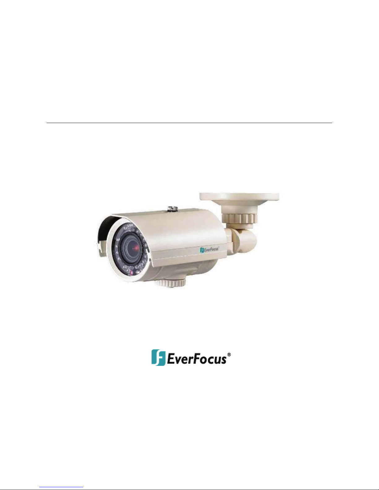
EZ655p
IR Day/Night plus WDR
IP66 Bullet Camera
User’s Manual
Copyright © EverFocus Electronics Corp,
Release Date: January, 2013

i
Cautions
1. Do not install the camera near electric or magnetic fields.
2. Never disassemble the camera beyond the recommendations in this
manual nor introduce materials other than those recommended
herein.
3. Try to avoid facing the camera toward the sun.
4. Keep the power cable away from water and other liquids and never
touch the power cord with wet hands.
5. Never install the camera in areas exposed to oil, gas or solvents.
6. Do not operate the camera beyond the specified temperature or
humidity. Use the dual voltage model at temperatures within -10°C
~50°C (14°F ~122°F) / the 12VDC model with heater at temperatures
within -40°C~50°C (-40°F~122°F) and humidity between 20%~ 80%; this
device is not rated as submersible.
7. Determine the polarity of the power adapter pigtail before connecting
the camera to the power source. The input power source is 12 VDC /
24 VAC~.

EZ655p
1. INTRODUCTION
Based on Sony Effio-P platform, the EZ655p is a bullet camera providing
700 TVL with Sony’s 1/3'' 960H image sensor. The double scan WDR (Wide
Dynamic Range) technology enables the camera to get detailed
information from the dark part of the image without saturation from the
bright part, which provides clear images under back light circumstances
where intensity of illumination can vary excessively.
The camera also provides 3D-DNR (Digital Noise Reduction) function,
which can save the HDD space of the connected DVR. Multiple functions
including dual voltages, 16x digital zoom, privacy mask and motion
detection are supported. The embedded 35 IR LEDs provide up to
60m/195ft. viewing range in low light or complete no light environment.
Along with the IP66 weather-resistant and vandal-proof housing design,
the EZ655p is an ideal design for both indoor and outdoor environment
.
1.1 FEATURES
• 1/3 ” SONY 960H WDR sensor at 0.03 Lux has 5x better native light
sensitivity before DSP low light boost
• Starlight super high sensitivity of 0.00006 Lux at F1.2 is achieved
through a sensitivity increase setting of up to 512x
• Extended IR range of 60m / 195ft. with 35 LEDs
• Split glass to prevent internal IR reflections
• True Day/Night with ICR module
• Vari-focal auto iris lens – optional 2.8~12mm or 5~50mm focal range,
external zoom and focus adjustment support
• Wide Dynamic Range expansion to deliver properly exposed images
despite bright light sources, deep shadows and/or unbalanced lighting
in the same scene
• Provides 2D, 3D-Noise Reduction to improve picture clarity while
enabling DVRs to improve disk storage utilization
• Motion detection for 4 configurable zones
• Privacy mask function for 15 configuration zones
• Provides digital zoom up to 16x
• Support Digital Image Stabilization (DIS)
• Easy bottom access to video test point and lens / OSD menu controls
inside weatherproof cover
• IP66 weather resistance
• Vandal resistance

EZ655p
2
1.2 PACKAGE CONTENTS
1. Camera x 1
2. Camera Base x 1
3. User Manual x 1
4. Power Adaptor Pigtail x 1
5. Test Lea d x 1
6. Accessory Kit x 1 (Hexagon Wrench x 1, L-Type Wrench x 1, Hexagon
Screw x 4 and Mounting Screw x 4)
1.3 OVERVIEW
1
2
3
4
1.4 DIMENSIONS
No. Name Description
1 Sunshield Protect the camera from the direct rays of the sun.
2
Bracket Lock
Knob
Loosen / tighten the bracket lock knob for
adjusting camera angles.
3 3-Axis Bracket For adjusting the camera angles.
4 Cover
Open it to control the OSD settings, LED
brightness, and to connect the Test Lead.
EZ655p
3
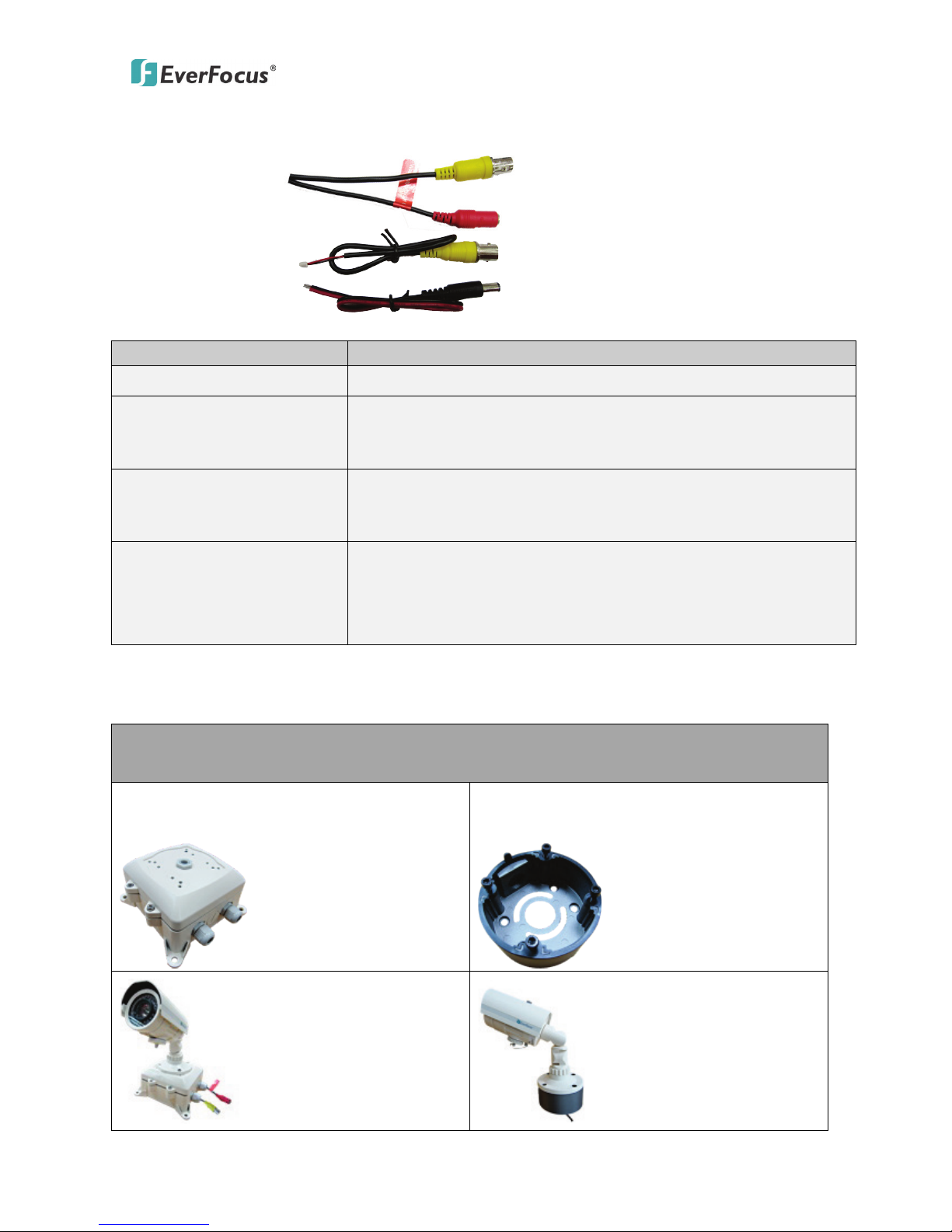
1.5 CABLE DEFINITIONS
Power Cable
Video-Out Cable
Test Lead
Power Adaptor Pigtail
Cable Name
Description
Video-Out Cable (BNC) Connects to a DVR or a monitor.
Power Cable
Connects to the 12 VDC / 24 VAC~ power source.
You can optionally use the supplied Power Terminal
Block or a power adapter.
Test Lea d
Connects one end to spot monitor port on the back
panel of the camera and the other end to a
portable monitor.
Power Adaptor Pigtail
Connects one end to the Power Cable, and the
other end to the 12 VDC / 24 VAC~ power source
(black wire to ground end; black / red wire to
positive end.)
1.6 OPTIONAL DEVICES
The following two items are used to contain and protect the camera
cables from rain.
Hood Camera Junction Box:
PBOX-A013
Hood Camera Junction Box:
PBOX-A024
EZ655p
4
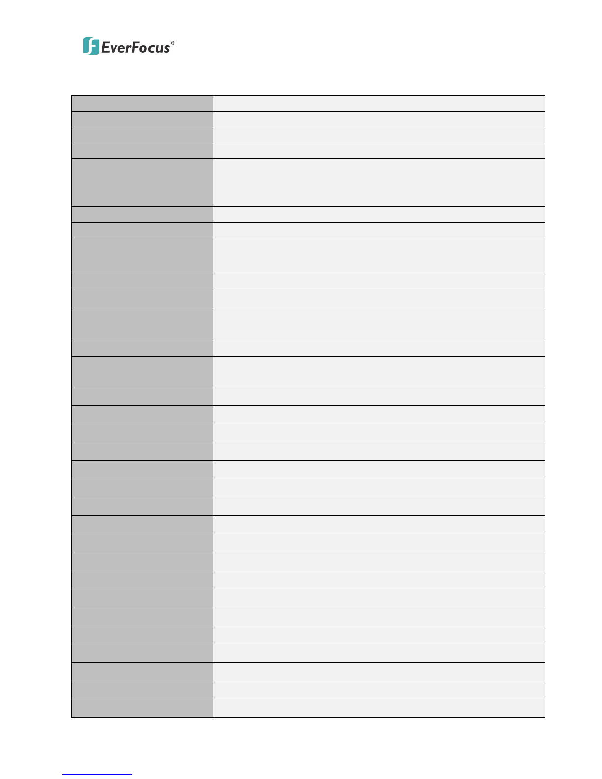
2. SPECIFICATIONS
Pickup Device
1/3" SONY 960H WDR CCD
Video Format
NTSC / PAL
Picture Elements
976 x 494 (NTSC), 976 x 582 (PAL)
Horizontal Resolution
700 TVL
Sensitivity
0.03 Lux at F=1.2
0.00006 Lux at F1.2/Sens-up 512x
0 Lux (IR on)
S/N Ratio
Over 52dB (AGC off)
Electronic Shutter
1/60 (1/50) ~ 1/100,000 sec.
Video Output
Main output BNC 1.0V p-p ,75ohm, Local test output,
cable provided
Gamma Correction
0.45
Lens Type DC Iris Vari-focal: 2.8~12mm or 5~50mm focal length
Back Light
Compensation
Off / BLC / HLC
Auto Gain Control
0~128 level adjustable
White Balance
ATW(1,800K~10,500K) / Push / User1 / User2 / Anti
CR / Manual / Push Lock
Sync. Mode
Internal
Day & Night Color, Auto (EXT On / Off)
OSD Menu
Yes
IR Emitters
35 long life LEDs
IR Configuration
Split glass isolation prevents internal reflections
IR Wavelength
850nm
IR Distance
60m / 195ft.
Smart IR Yes
2D, 3D-DNR Off / Low / MidLow / Mid / MidHigh / High (2D+3D)
WDR
On / Off
Digital Slow Shutter
Up to 512x
Mirror
Off / V-Flip / H-Flip / HV-Flip
Digital E-Zoom
0~255 Level Adjustable(1x~16x) PAN/TILT
Motion Detection
On / Off for 4 selectable zones
Privacy Mask On / Off for 15 selectable zones
DIS On / Off
Weather Proof
IP66 rated
Heater
Yes, built-in (12 VDC model only)
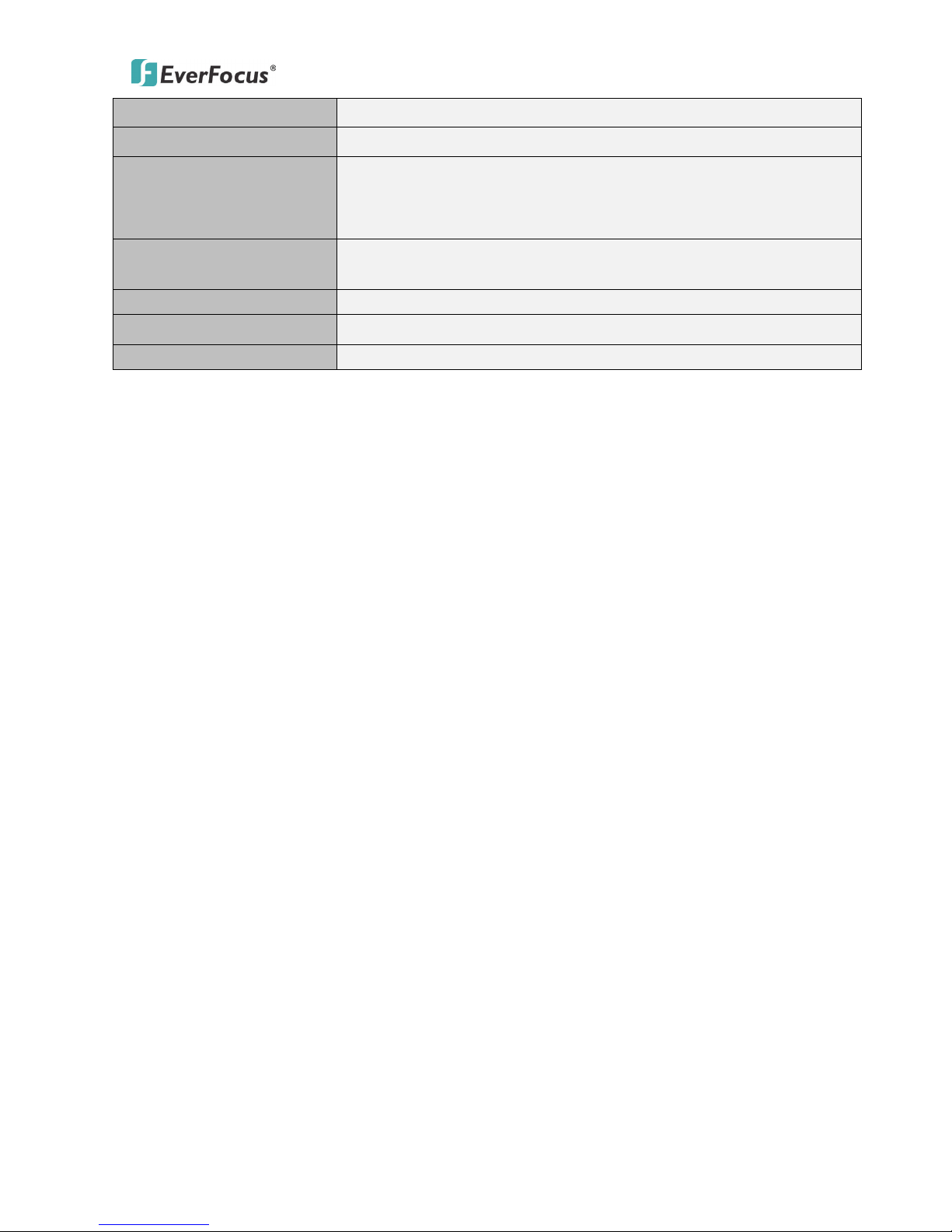
EZ655p
5
Vandal Resistant
Yes
Power Source
12 VDC / 24 VAC~ ; 12 VDC
Power Consumption
12 VDC: 7.2W max. (IR on)
12 VDC: 14.5W max. (IR + Heater on)
12 VAC~:6.5W max. (IR on)
Operating
Temperature
-10°C~50°C / 14°F~122°F (Dual voltage model)
-40°C~50°C / -40°F~122°F (12 VDC with heater)
Dimensions (O.D x H
100 x 125 x 230mm / 3.94” x 4.72” x 9.06”
Weight
1.8kg / 3.96lbs
Certifications
CE, FCC
EZ655p
6
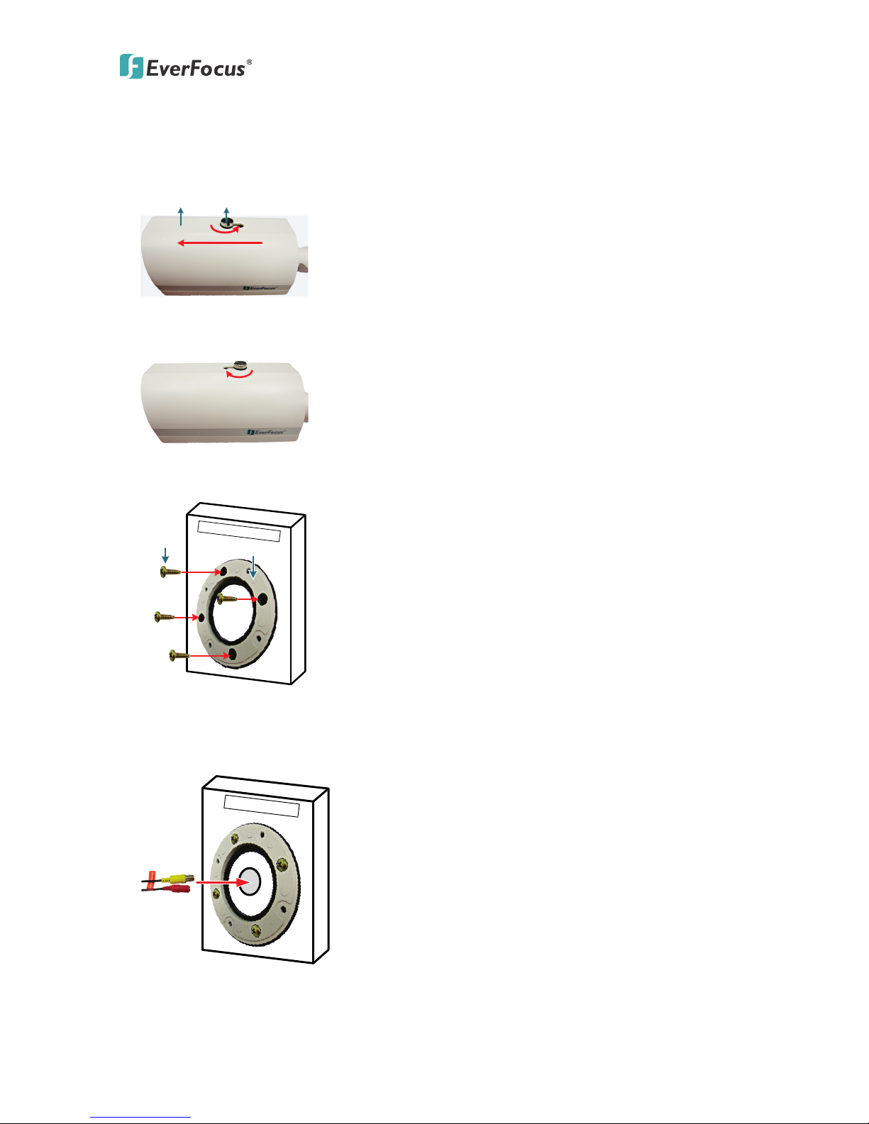
3. INSTALLATION
1. Loosen the screw on the sunshield and push the rear of the sunshield
to the front.
Sunshield Screw
2. Adjust the sunshield to an appropriate position and tighten the
screw.
3. Screw through the four black holes on the Camera Base to the wall /
ceiling using the Mounting Screws.
Mounting
Screw
Camera Base
Wall / Ceiling
4. If you want to wire the cables through the wall /ceiling, drill a hole on
the wall / ceiling at the center of the Camera Base. Ignore this step if
you want to wire the cables from the side cut of the base.
Wall / Ceiling
Hole
Cables
 Loading...