

EverFocus EMV800 HD, EMV1200 HD User Manual

EMV800 HD / EMV1200 HD
8 / 12 Channels Mobile DVR
User’s Manual
Copyright © EverFocus Electronics Corp.
Release Date: September, 2016

E VERFOCUS ELECTRONICS CORPORATION
EMV800 HD / EMV1200 HD
Mobile DVR
User’s Manual
1995-2016 EverFocus Electronics Corp.
www.everfocus.com.tw
Disclaimer
All the images including product pictures or screen shots in this document are for example only. The
images may vary depending on the product and software version. Information contained in this document
is subject to change without notice.
Copyright
All rights reserved. No part of the contents of this manual may be reproduced or transmitted in any form
or by any means without written permission of the EverFocus Electronics Corporation.
Windows is a registered trademark of the Microsoft Corporation.
Linksys is a registered trademark of the Linksys Corporation.
D-Link is a registered trademark of the D-Link Corporation.
DynDNS is a registered trademark of the DynDNS.org Corporation.
Other product and company names mentioned herein may be the trademarks of their respective owners.

Safety Precautions
Refer all work related to the installation of this product to qualified service personnel or
system installers.
Do not block the ventilation openings or slots on the cover.
Do not drop metallic parts through slots. This could permanently damage the appliance.
Turn the power off immediately and contact qualified service personnel for service.
Do not attempt to disassemble the appliance. To prevent electric shock, do not remove
screws or covers. There are no user-serviceable parts inside. Contact qualified service
personnel for maintenance. Handle the appliance with care. Do not strike or shake, as this
may damage the appliance.
Do not expose the appliance to water or moisture, nor try to operate it in wet areas. Do
take immediate action if the appliance becomes wet. Turn the power off and refer servicing
to qualified service personnel. Moisture may damage the appliance and also may cause
electric shock.
Do not use strong or abrasive detergents when cleaning the appliance body. Use a dry cloth
to clean the appliance when it is dirty. When the dirt is hard to remove, use a mild
detergent and wipe gently.
Do not overload outlets and extension cords as this may result in a risk of fire or electric
shock.
Do not operate the appliance beyond its specified temperature, humidity or power source
ratings. Do not use the appliance in an extreme environment where high temperature or
high humidity exists. Use the mobile DVR at temperatures within -40°C~55°C / -40°F~131°F
(Storage). The input power source is between 9V DC and 36V DC.
Read Instructions
All the safety and operating instructions should be read before the unit is operated.
Retain Instructions
The safety and operating instructions should be retained for future reference.
Heed Warnings
All warnings on the unit and in the operating instructions should be adhered to.
ii

Follow Instructions
All operating and use instructions should be followed.
Cleaning
Unplug the unit from the outlet before cleaning. Do not use liquid cleaners, abrasive or
aerosol cleaners. Use a damp cloth for cleaning.
Attachments
Do not use attachments not recommended by the product manufacturer as they may
cause hazards.
Water and Moisture
Do not use this unit near water-for example, near a bath tub, wash bowl, kitchen sink, or
laundry tub, in a wet basement, near a swimming pool, in an unprotected outdoor
installation, or any area which is classified as a wet location.
Servicing
Do not attempt to service this unit by yourself as opening or removing covers may expose
you to dangerous voltage or other hazards. Refer all servicing to qualified service
personnel.
Power Cord Protection
Power supply cords should be routed so that they are not likely to be walked on or pinched
by items placed upon or against them, playing particular attention to cords and plugs,
convenience receptacles, and the point where they exit from the appliance.
Object and Liquid Entry
Never push objects of any kind into this unit through openings as they may touch
dangerous voltage points or short-out parts that could result in a fire or electric shock.
Never spill liquid of any kind on the unit.
RTC (Real Time Clock) Battery
When encounter failure of time calibration of your DVR, the issue may be caused by
running-out of RTC battery. Users will have to change the RTC battery on the main board
of the Mobile DVR.
ATTENTION! This is a class A product which may cause radio interference in a domestic
environment; in this case, the user may be urged to take adequate measures.
iii

Federal Communication Commission Interference Statement
This equipment has been tested and found to comply with the limits for a Class B digital
device, pursuant to Part 15 of the FCC Rules. These limits are designed to provide
reasonable protection against harmful interference in a residential installation. This
equipment generates, uses and can radiate radio frequency energy and, if not installed
and used in accordance with the instructions, may cause harmful interference to radio
communications. However, there is no guarantee that interference will not occur in a
particular installation. If this equipment does cause harmful interference to radio or
television reception, which can be determined by turning the equipment off and on, the
user is encouraged to try to correct the interference by one of the following measures:
•Reorient or relocate the receiving antenna.
•Increase the separation between the equipment and receiver.
•Connect the equipment into an outlet on a circuit different from that to which the
receiver is connected.
•Consult the dealer or an experienced radio/TV technician for help.
FCC Caution: Any changes or modifications not expressly approved by the party
responsible for compliance could void the users’ authority to operate this equipment.
WEEE
The information in this manual was current upon publication. The manufacturer reserves the right to
revise and improve his products. Therefore, all specifications are subject to change without prior
notice. Manufacturer is not responsible for misprints or typographical errors.
Please read this manual carefully before installing and using this unit. Be sure to keep it handy for
later reference.
This Product is RoHS compliant.
Your EverFocus product is designed and manufactured with high quality materials and
components which can be recycled and reused. This symbol means that electrical and
electronic equipment, at their end-of-life, should be disposed of separately from your
household waste. Please, dispose of this equipment at your local community waste
collection/recycling centre. In the European Union there are separate collection systems
for used electrical and electronic product.
Please, help us to conserve the environment we live in!
iv

TABLE OF CONTENTS
1. Introduction ................................................................................................................... 1
1.1 Features .......................................................................................................................... 3
1.2 Packing List ...................................................................................................................... 4
1.3 Optional Accessories ....................................................................................................... 4
1.4 Front Panel ...................................................................................................................... 5
1.5 Rear Panel ....................................................................................................................... 6
2. Getting Started .............................................................................................................. 8
2.1 Installation ...................................................................................................................... 8
2.1.1 Mounting ..................................................................................................................... 9
2.2 Hard Disk Installation .................................................................................................... 12
2.3 SD Card Installation ....................................................................................................... 14
2.4 Vehicle Connection ....................................................................................................... 16
2.4.1 Connecting to a Truck with 24 VDC .......................................................................... 16
2.4.2 Connecting to a Car with 12 VDC .............................................................................. 17
2.5 Basic Connection ........................................................................................................... 18
2.5.1 Power Harness Cable ................................................................................................ 19
2.5.2 Video Cable / Power-Out Cable ................................................................................ 20
2.5.2.1 Camera Connection ........................................................................................ 21
2.5.2.2 Recording Resolution Table ........................................................................... 23
2.5.3 Audio Cable ............................................................................................................... 25
2.5.4 D-Sub Cable ............................................................................................................... 26
2.6 Monitor Connection ...................................................................................................... 27
2.7 Turning On / Off the Power .......................................................................................... 27
2.8 Accessing the Mobile DVR ............................................................................................ 28
2.9 Connecting the Mobile DVR to the Network ................................................................ 33
2.9.1 Router or LAN Connection ........................................................................................ 33
2.9.2 Direct High-Speed Connection .................................................................................. 36
2.9.3 One-to-One Connection ............................................................................................ 37
3. General Operation ....................................................................................................... 41
3.1 USB Mouse Operation .................................................................................................. 41
3.1.1 How to Select a Channel / Enable Audio Out ........................................................... 41
v

3.1.2 OSD Root Menu ........................................................................................................ 42
3.1.3 Field Input Options.................................................................................................... 42
3.2 General Operation ........................................................................................................ 44
3.2.1 Login .......................................................................................................................... 44
3.2.2 Forget Your Password ............................................................................................... 45
3.2.3 Camera Selection ...................................................................................................... 45
3.2.4 Audio Selection ......................................................................................................... 46
4. OSD Root Menu ........................................................................................................... 47
4.1 PTZ ................................................................................................................................. 49
4.1.1 Express Control of PTZ .............................................................................................. 51
4.2 Layout Switching ........................................................................................................... 52
4.3 Channel Switching ......................................................................................................... 52
4.4 Display ........................................................................................................................... 53
4.5 Sequence ....................................................................................................................... 55
4.6 Zoom ............................................................................................................................. 55
4.7 Archiving the Recordings or Log Data to the USB or FTP ............................................. 57
4.8 Logout ........................................................................................................................... 60
4.8.1 Temporarily Logout ................................................................................................... 61
5. Search and Playback..................................................................................................... 63
5.1 Quick Playback .............................................................................................................. 63
5.2 Playback Bar .................................................................................................................. 64
5.3 Searching the Recordings for Playing Back ................................................................... 66
5.3.1 Time Search ............................................................................................................... 66
5.3.2 Event Search ............................................................................................................. 67
5.3.3 Snapshot Search ........................................................................................................ 68
6. System ......................................................................................................................... 70
6.1 Camera .......................................................................................................................... 72
6.1.1 Basic Setting .............................................................................................................. 72
6.1.2 Adjust Setting ............................................................................................................ 74
6.1.2.1 eZ Controller (Control Camera OSD Setting from DVR End)..................................... 75
6.2 Record & Playback ........................................................................................................ 76
6.2.1 Record ....................................................................................................................... 76
6.2.2 Playback .................................................................................................................... 77
vi

6.3 Event ............................................................................................................................. 78
6.3.1 Alarm ......................................................................................................................... 78
6.3.2 Video Loss ................................................................................................................. 80
6.3.3 Motion....................................................................................................................... 82
6.3.4 GPS Event .................................................................................................................. 85
6.3.5 G-Sensor Event .......................................................................................................... 87
6.3.6 Other ......................................................................................................................... 89
6.4 Hard Disk ....................................................................................................................... 97
6.4.1 Disk ............................................................................................................................ 97
6.4.2 SD Card ...................................................................................................................... 98
6.4.3 Lock/Format .............................................................................................................. 99
6.5 Display Setting............................................................................................................. 100
6.5.1 Monitor OSD ........................................................................................................... 100
6.5.2 M/T SEQ .................................................................................................................. 101
6.6 Network Settings ......................................................................................................... 102
6.6.1 LAN .......................................................................................................................... 102
6.6.2 Wireless ................................................................................................................... 105
6.6.3 Mobile ..................................................................................................................... 107
6.6.4 Email ........................................................................................................................ 108
6.6.5 DDNS ....................................................................................................................... 109
6.6.6 FTP ........................................................................................................................... 115
6.6.7 Alarm Server ........................................................................................................... 116
6.6.8 Remote/Mobile ....................................................................................................... 117
6.6.9 Network Test ........................................................................................................... 118
6.6.10 Xfleet ................................................................................................................... 119
6.7 Schedule Setting ......................................................................................................... 120
6.7.1 Express Setup .......................................................................................................... 120
6.7.2 Holidays ................................................................................................................... 121
6.7.3 Schedule .................................................................................................................. 122
6.8 System Setting ............................................................................................................ 125
6.8.1 Date / Time ............................................................................................................. 125
6.8.2 Daylight Saving ........................................................................................................ 127
6.8.3 User Group .............................................................................................................. 128
6.8.4 User Management .................................................................................................. 130
6.8.5 I/O Control .............................................................................................................. 132
6.8.6 EKB200 Setting ........................................................................................................ 134
6.8.7 Miscellaneous ......................................................................................................... 136
6.9 Information ................................................................................................................. 138
6.9.1 System ..................................................................................................................... 138
vii

6.9.2 Log ........................................................................................................................... 140
7. Remote Access to the Mobile DVR.............................................................................. 141
7.1 Accessing the Mobile DVR on the Network ................................................................ 141
7.2 Remote Live View ....................................................................................................... 145
7.3 Menu Bar..................................................................................................................... 146
7.3.1 Camera .................................................................................................................... 147
7.3.1.1 Basic Setting ................................................................................................. 147
7.3.1.2 Adjust Setting ............................................................................................... 149
7.3.2 Record ..................................................................................................................... 151
7.3.3 Event ....................................................................................................................... 152
7.3.3.1 Alarm................................................................................................................................... 152
7.3.3.2 Video Loss .......................................................................................................................... 154
7.3.3.3 Motion ................................................................................................................................ 155
7.3.3.4 GPS Event .......................................................................................................................... 158
7.3.3.5 G-Sensor Event ................................................................................................................. 160
7.3.3.6 Other ................................................................................................................................... 161
7.3.4 Disk .......................................................................................................................... 169
7.3.4.1 Disk ...................................................................................................................................... 169
7.3.4.2 Lock/Format ...................................................................................................................... 170
7.3.5 Display Setting......................................................................................................... 171
7.3.5.1 Monitor OSD ..................................................................................................................... 171
7.3.5.2 M/T SEQ ............................................................................................................................. 172
7.3.6 Network .................................................................................................................. 173
7.3.6.1 LAN ...................................................................................................................................... 173
7.3.6.2 Wireless .............................................................................................................................. 176
7.3.6.3 Mobile ................................................................................................................................ 177
7.3.6.4 Email.................................................................................................................................... 178
7.3.6.5 DDNS ................................................................................................................................... 179
7.3.6.6 FTP ....................................................................................................................................... 184
7.3.6.7 Alarm Server ..................................................................................................................... 185
7.3.6.8 Remote/Mobile ............................................................................................................... 186
7.3.6.9 Xfleet ................................................................................................................................... 186
7.3.7 Schedule .................................................................................................................. 187
7.3.7.1 Express Setup ................................................................................................................... 187
7.3.7.2 Holiday................................................................................................................................ 188
7.3.7.3 Schedule ............................................................................................................................. 189
7.3.8 System Setting ........................................................................................................ 192
7.3.8.1 Date/Time.......................................................................................................................... 192
7.3.8.2 Daylight Saving ................................................................................................................. 194
viii

7.3.8.3 User Group ........................................................................................................................ 195
7.3.8.4 User Management .......................................................................................................... 197
7.3.8.5 I/O Control ........................................................................................................................ 199
7.3.8.6 EKB200 Setting ................................................................................................................. 201
7.3.8.7 Miscellaneous................................................................................................................... 203
7.3.9 Information ............................................................................................................. 204
7.3.9.1 System ................................................................................................................................ 204
7.3.9.2 Log ....................................................................................................................................... 205
7.3.10 Copy .................................................................................................................... 206
7.3.11 Search .................................................................................................................. 209
7.3.11.1 Time Search .................................................................................................................... 209
7.3.11.2 Event Search ................................................................................................................... 210
7.3.12 PTZ ....................................................................................................................... 212
8. Specifications ............................................................................................................. 214
9. Troubleshooting ......................................................................................................... 216
Appendix A: Network Overview ......................................................................................... 217
Appendix B: Linksys & D-Link Port Forwarding ................................................................... 221
Appendix C: Timing of Alarm Modes .................................................................................. 225
Appendix D: Express Setup Recording Value Selection Rules .............................................. 228
Appendix E: IR Remote Control .......................................................................................... 230
Appendix F: RTSP URL Syntax............................................................................................. 231
Appendix G: Tested Card Brands ........................................................................................ 234
Appendix H: Recording Backup through EF Reader ............................................................. 235
Appendix I: Auto HDD Retry Mechanism ............................................................................ 236
ix

EMV800 HD / EMV1200 HD Mobile DVR
3G/4G/
12VDC
SAE-J1455
1
Chapter
1. Introduction
The latest EverFocus digital video recorder generation is based on H.264 compression technology,
resulting in enhanced recording capacity and improved network image transmission speed with
high image quality. The EMV800 HD / EMV1200 HD can support 8 / 12 channels analog SD/HD
cameras, delivering up to 1080p live view resolution.
Its comprehensive features along with the embedded 3-axis g-sensor function enable the almost
universal application of this mobile DVR series. It supports various interfaces such as three USB
ports / RS-485 / RS-232 / Panic Button / CAN bus / GPS, 3G, 4G and Wi-Fi Antenna. The design of
RCA video/audio outputs at front panel makes your installation easy. You can install one 2.5”hard
disk in the HD mobile DVR. You can also install one SD Card for alarm event backup recording. The
User Interface has been specially designed to fit mobile small-sized monitor.
EMV800 HD / EMV1200 HD are equipped with anti-shock and anti-vibration housing. The aviation
M12 connectors are also equipped. The power supply supports voltage regulator, and delay on/off.
In addition, the HD mobile DVRs are SAE-J1455, EN50155, E-Mark, CE and FCC certified.
You can use EverFocus Mobile Applications, MobileFocus, to remotely view the camera streams
from the mobile DVR through your handheld devices; or use EverFocus Xfleet system for remote
fleet management. You can also use EverFocus EF-Reader to remotely back up recordings from the
HDD/SD card of the mobile DVRs. The mobile DVR series is the ideal solution for your mobile
surveillance needs.
EMV 1080p Series Models
Model
EMV800 HD 8 CH 8/1 CH 8/2 CH Yes Yes Yes Yes
EMV1200 HD 12 CH 8/1 CH 8/2 CH Yes Yes Yes Yes
Video
In
Audio
In/Out
Alarm
In/Out
WiFi
Power-Out
Anti-Vibration
Bracket
Standard
1

EMV800 HD / EMV1200 HD Mobile DVR
Power Supply
GPS
Wi-Fi
3G
4G
Main
Monitor
(VGA)
Panic Button
RS-232 CAN bus
(optional)
PTZ Camera
*Analog SD/HD
Camera 1 ~ 12
**12VDC Power
Output 1 ~ 12
*Audio Input
1 ~ 8
Main Monitor (BNC)
Call Monitor
Notebook / PC
Speaker
Mouse
USB Storage Device
SD Card Slot
2.5" HDD x 1
HDD Key Lock
WAN
CMS (Client PC)
Main Monitor
(RCA)
Function Key
(reserved)
System Diagram
* This diagram uses EMV1200 HD as an example. The EMV800 HD has 8 video inputs and 8 audio
inputs.
** The EMV800 HD / EMV1200 HD have 8 / 12 power output sets (+/-) respectively. Each power
out set (+/-) provides 12VDC, 500mA power output.
2

EMV800 HD / EMV1200 HD Mobile DVR
1.1 Features
• Supports analog SD / HD cameras
• Up to 1080p resolution for recording *
• Dual-stream from H.264 video compression
• eZ.Controller function: Control camera OSD settings and PTZ operation directly from DVR
end
• Supports HDD (up to 1TB) or SSD
• Provides one 1Gb Ethernet port
• 3-axis G-sensor embedded
• Multiple serial interfaces
• Internal temperature control (built-in 2 heaters)
• IR remote control function
• Aviation (M12) connectors adopted
• Archives recordings to the USB storage device
• Supports mobile applications (MobileFocus)
• Multiple network monitoring: Web viewer, Xfleet (Server System), EF Reader (Windows
Application)
• Certificates: CE, FCC, EN50155, E-Mark, SAE-J1455 (shock & vibration only)**
• 3G, 4G LTE function / GPS function / Wi-Fi function (Optional) ***
* There are some restrictions for 1080p camera recordings. Please refer to 2.5.2.1 Camera
Connection for more details.
** To meet the EN50155 standard, the Z-type mounting bracket is required; to meet the SAE-
J1455 standard, the anti-vibration mounting bracket is required. Please refer to 2.1.1
Mounting for more details.
*** Requires an external 3G / 4G / GPS / Wi-Fi antenna, please refer to 1.3 Optional Accessories.
3

EMV800 HD / EMV1200 HD Mobile DVR
1.2 Packing List
• HD Mobile DVR x 1
• HDD Tray (with two HDD lock keys and 8 screws packed inside the tray) x 1 (see 2.2 Hard
Disk Installation)
• Mounting Bracket (you can use either bracket to mount the MDVR to the vehicle, please
order either one you preferred before shipping. The two types of mounting bracket cannot
be used simultaneously. See 2.1.1 Mounting for more details.
- Z-Type Bracket x 2 (includes Long Screw with washers x 4; Short Screw with washers x 4)
Note: To meet the EN50155 standard, Z-Type Bracket is required.
- Anti-Vibration Bracket x 1 (already installed on the mobile DVR)
Note: To meet the SAE-J1455 standard, Anti-Vibration Bracket is required.
• IR Remote Control (with two AAA batteries. See Note 4) x 1
• Power Harness Cable x 1
• Video Cable x 3 (EMV1200 HD); x2 (EMV800 HD) (see 2.4.2 Video Cable / Power-Out Cable)
• Audio Cable x 1 (see 2.4.3 Audio Cable)
• D-Sub Cable x 1 (see 2.4.4 D-Sub Cable)
• Power-Out Cable x 3 (EMV1200 HD); x2 (EMV800 HD) (see 2.4.2 Video Cable / Power-Out
Cable)
• CD x 1 (Please see Note 3.)
• Quick Installation Guide x 1
Note:
1. Equipment configurations and supplied accessories vary by country. Please consult your
local EverFocus office or agents for more information. Please also keep the shipping carton
for possible future use.
2. Contact the shipper if any items appear to have been damaged in the shipping process.
3. The CD contains the IP Utility software, User Manual and Quick Installation Guide.
4. Risk of explosion if battery is replaced by an incorrect type. Dispose of used batteries
according to the instructions.
a. Use only two AAA dry cell batteries.
b. Do not dispose of the batteries in a fire as it may explode.
1.3 Optional Accessories
• 3G Antenna: For using 3G network function
• 4G Antenna: For using 4G LTE network function (LTE frequency bands differ among regions)
• GPS Antenna: For using GPS function
• Wi-Fi Antenna: For using Wi-Fi function
4
EMV800 HD / EMV1200 HD Mobile DVR
1
7
9
5
3
4
6
8
1
10
2
No.
Name
Description
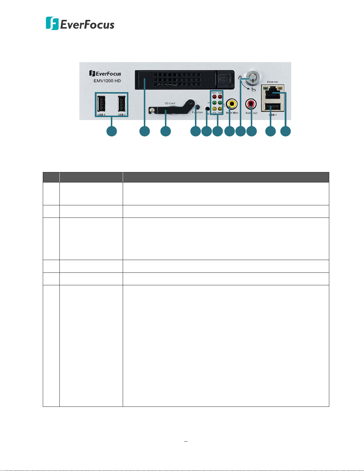
1.4 Front Panel
EMV800 HD / EMV1200 HD
1 USB2.0 Port
Three USB2.0 ports for connecting to the USB storage device or
mouse.
2 HDD Drive Tray Install a 2.5” HDD for recording.
Insert a SD / SDHC card (up to 32GB) for alarm event backup
3 SD Card Slot
recording (see 2.3 SD Card Installation). To see the SD card info, see
6.4.2 SD Card. To enable the SD card function, see 6.3.1 Alarm. You
can also see Appendix G for tested card brands.
4 Function Key This Function key is currently reserved.
5 IR Receiver Receives data from the infrared remote control.
• Alarm: Turns on when the connected alarm I/O is triggered;
turns off when the alarm I/O stops being triggered.
• GPS: Turns on continuously when the mobile DVR is receiving
GPS data.
• System Fail: Turns off when system is acting normally. Turns on
6 System LEDs
when these events occur: System Clock Error / Fan Fail / Disk
Temperature Over / Disk Fail / Disk Off / Network Loss.
• Heater: Blinks when heater on; off blinking when heater off.
• HD R/W: Blinks when the HDD is reading or writing.
• Power: Turns on continuously when the power is supplied. Blinks
when Battery power error occurs (lower than 9V or higher than
36V) or 12VDC power supply error.
5

EMV800 HD / EMV1200 HD Mobile DVR
1 2 3 4 5 6
7 8 9
11
1210
EMV1200 HD
1 2 3 4 5 6
7 8 9
11
12
10
EMV800 HD
RCA video output for connecting to a monitor for live view, playback
and displaying OSD.
7 Main Monitor
Note this mobile DVR has three Main Monitor outputs (one on the
front panel and the other two on the rear panel). All of the Main
Monitor ports can be connected simultaneously.
8 HDD Key Lock Lock and unlock the HDD tray.
RCA audio output for connecting to the speakers. The audio output
9 Audio Out
only works during playback. Speakers with a (built-in) amplifier and
external power supply are required.
10 Ethernet Port One RJ-45 port for connecting to the network.
1.5 Rear Panel
No. Name Description
1 Antenna 1 (3G/4G)
2 Antenna 2 (4G)
Connects to the 3G or 4G Antenna for using 3G / 4G LTE
function.
Connects to the 4G Antenna for using 4G LTE function. Note that
the 4G function is required to use both Antenna 1 and 2.
3 Antenna 3 (GPS) Connects to the GPS Antenna for using GPS function.
4 Antenna 4 (Wi-Fi) Connects to the Wi-Fi antenna for using Wi-Fi function.
6

EMV800 HD / EMV1200 HD Mobile DVR
5 Main Monitor (VGA)
6 D-Sub Connector
7 Main Monitor (BNC)
8 Call Monitor (BNC)
9 Audio Input
10 Video Input
VGA video output for connecting to the main monitor for live
view, playback and displaying OSD.
D-Sub connector for connecting to the Alarm I/O, RS-232 (CAN
bus) or RS-485 devices (such as analog PTZ cameras). For details,
please refer to 2.4.4 D-Sub Cable.
BNC video output for connecting to the main monitor for live
view, playback and displaying OSD.
Note the mobile DVR has 3 Main Monitor outputs (one on the
front panel and the other 2 on the rear panel). All of the Main
Monitor ports can be connected simultaneously.
BNC video output for connecting to the call monitor for
displaying the live view.
D-Sub connector for connecting to the supplied Audio Cable. For
details, please refer to 2.4.3 Audio Cable. Microphones with a
(built-in) amplifier and external power supply are required.
M12 connector for connecting to the supplied Video Cable. You
can then connect analog HD / SD cameras to the Video Cable.
* The MDVR doesn’t support HD-TVI / HD-CVI / HD-SDI cameras.
Note that if you want to connect different resolution types of
cameras (1080p / 720p / D1) to the MDVR, there are some
instructions to follow, please refer to 2.5.2.1 Camera
Connection for more details.
11 DC Power Input
12 12VDC Power Outputs
Power harness cable for connecting to 9 ~ 36VDC power source.
For details, please refer to 2.4.1 Power Harness Cable.
12VDC power supply to the connected cameras (supply 12VDC,
500mA per camera). Please refer to 2.4.2 Video Cable / Power-
Out Cable.
7

EMV800 HD / EMV1200 HD Mobile DVR
Bottom of passenger seat next to the driver
2
Chapter
2. Getting Started
2.1 Installation
Before installation, choose a location in the vehicle where it can:
• Provide convenient access for installing or removing the hard disk
• Allow air to flow around the fan vents. Inadequate or improper air flow can impede proper
operation of the mobile DVR
Please avoid installing the mobile DVR to the following locations in the vehicle:
• That is subject to high vibration / sunlight levels
• That is subject to be drenched of the rain
• Where passengers can interfere with the mobile DVR
• Next to a heater duct
The following table lists the recommended location options in the vehicle:
Location
Bottom of glove box- horizontal mount
Underneath bulkhead-horizontal mount Yes Yes No Yes
Front of bulkhead-horizontal mount Yes Yes Yes Yes
Beside deriver seat-horizontal mount
Note: Do not install the mobile DVR on the floor or on the transmission access hatch. These
locations have the highest levels of vibration and may be subject to water damage.
Convenient
Operation
Yes Yes Yes Yes
No Yes Yes Yes
Yes Yes Yes Yes
Easy to
Install
Low
Vibration
Good
Air Flow
8
EMV800 HD / EMV1200 HD Mobile DVR
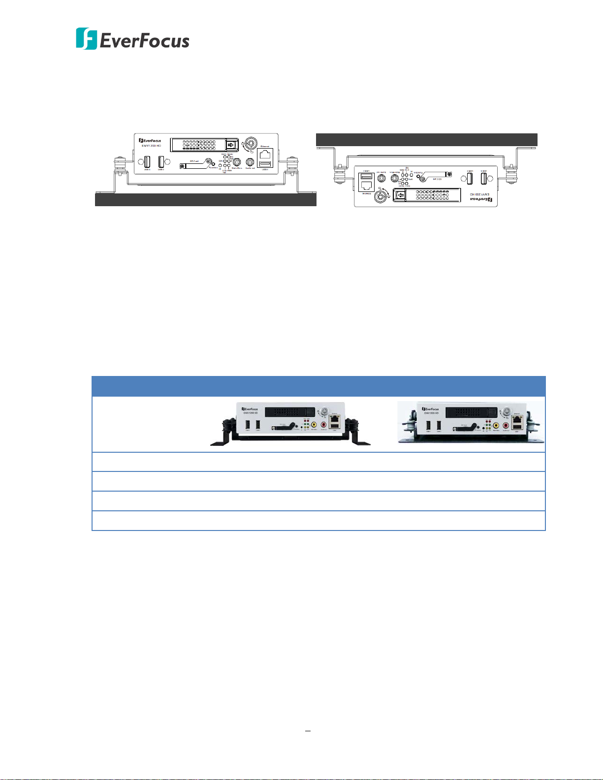
Support-Mount Suspend-Mount
Interface
Interface
2.1.1 Mounting
You can use the provided mounting bracket in the package to mount the mobile DVR inside
the vehicle. Two mounting types are available, Support-Mount and Suspend-Mount.
If the mounting bracket you ordered is a Z-Type Bracket, both of the above two mounting
types are supported. Please note that to meet the EN50155 standard for the mobile DVR, the
Z-Type Bracket is required to be used.
If the mounting bracket you ordered is an Anti-Vibration Bracket, only the Support-Mount is
supported. Please note that to meet the SAE-J1455 standard for the mobile DVR, the Anti-
Vibration Bracket is required to be used.
Z-Type Bracket Anti-Vibration Bracket
EN50155 Standard Yes -
SAE-J1455 Standard - Yes
Support-Mount Yes Yes
Suspend-Mount Yes -
9
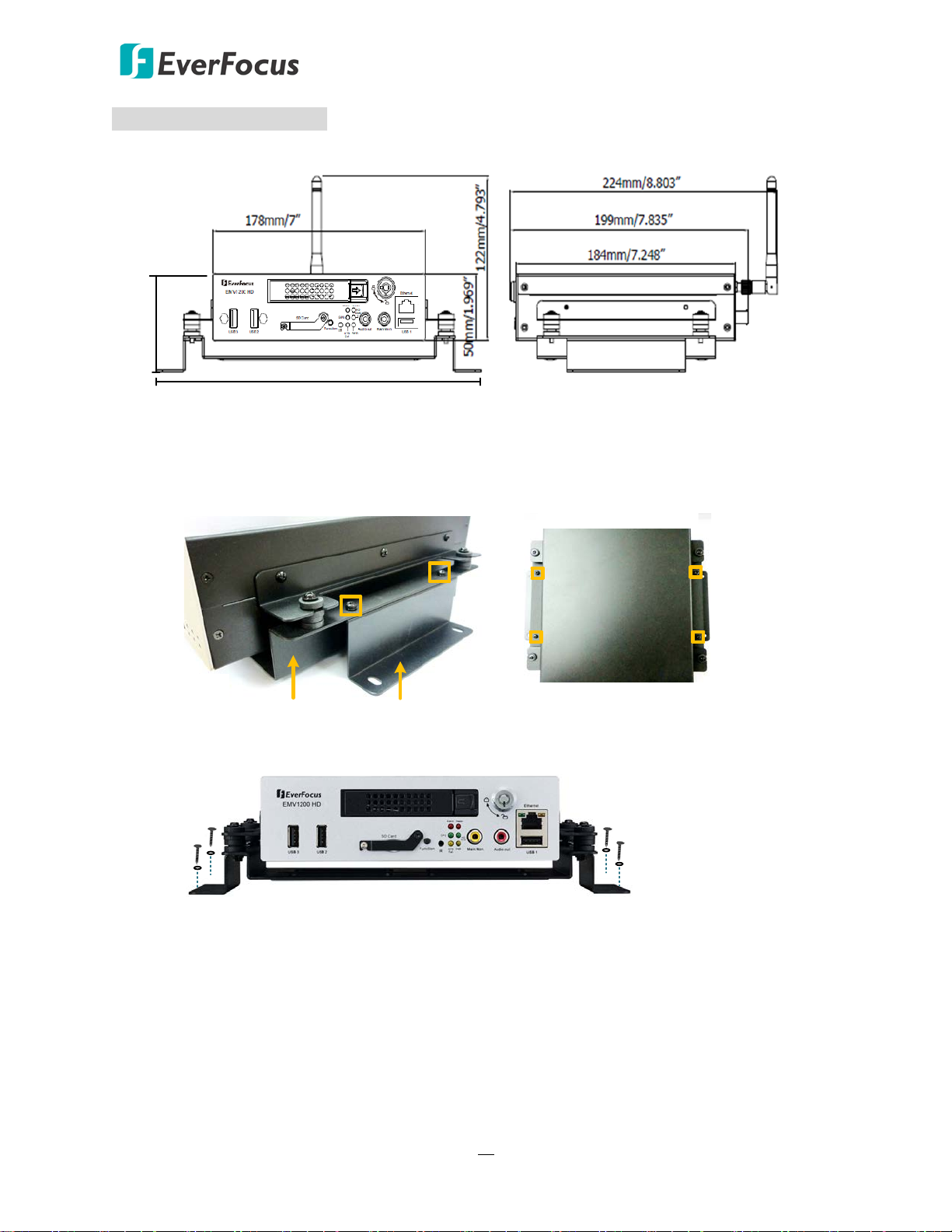
EMV800 HD / EMV1200 HD Mobile DVR
With Z-Type Bracket
272mm/10.709"
73mm/2.866"
Z-Type Bracket
Fixing Bracket
Dimensions and Installation
To install the mobile DVR onto a surface using Z-Type Brackets:
1. Attach the supplied two Z-Type Brackets to the Fixing Bracket on the mobile DVR. Use the
supplied four Short Screws with washers to screw the Z-Type Brackets to the Fixing
Bracket.
2. Screw the mobile DVR to the surface using the supplied four Long Screws with washers.
10
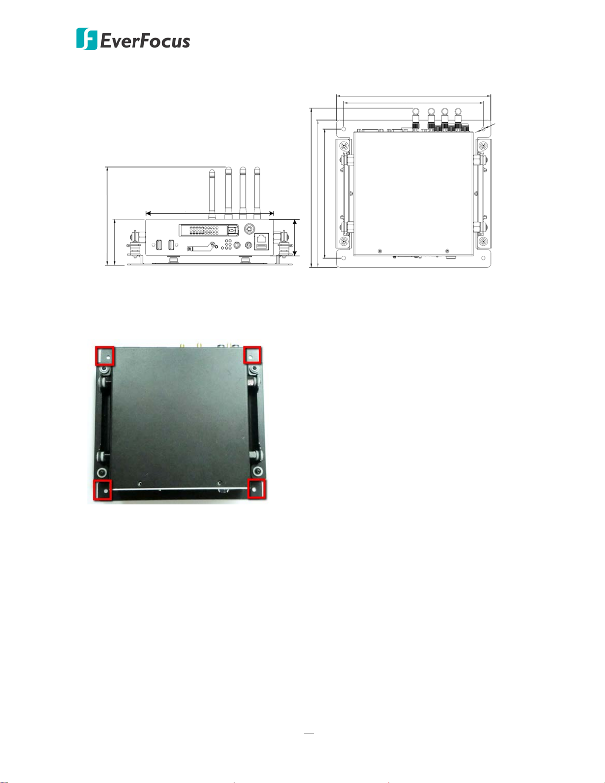
EMV800 HD / EMV1200 HD Mobile DVR
136.3mm/5.4"
63.4mm/2.5"
178mm/7"
50mm/1.969"
229.6mm/9"
207.4mm/8.2"
235.7mm/9.3"
218mm/8.6"
192mm/7.6"
Ø5.5mm/Ø0.2"
To install the mobile DVR onto a surface using Anti-Vibration Bracket:
The Anti-Vibration Bracket is already installed on the mobile DVR. Users need to prepare four
screws to screw the mobile DVR onto a surface. The screw diameter on the Anti-Vibration
Bracket is Ø5.5mm / Ø0.2”.
11
EMV800 HD / EMV1200 HD Mobile DVR
Locked
Unlocked
Release LatchLocking Arm
HDD Tray
Locking Arm
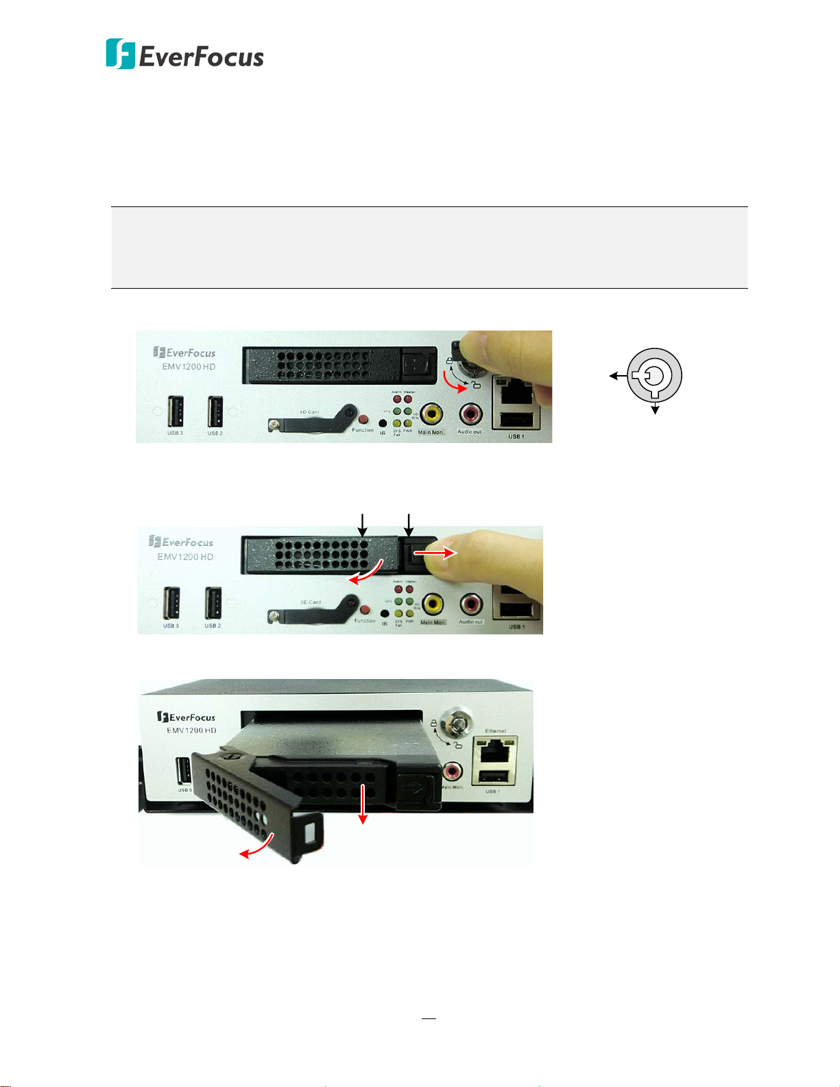
2.2 Hard Disk Installation
The mobile DVRs supply with a 2.5” HDD tray for inserting a Hard Disk for video recordings.
Please follow the steps below to install the Hard Disk.
Note: The mobile DVR does not support hot swap for the hard disk. Ensure to power off the
mobile DVR before removing the hard disk. Also ensure to remove the hard disk only after
the power was completely shut off. This would protect and extend the operating life of the
hard disk.
1. Make sure the mobile DVR is powered-off, and unlock the HDD Tray using the supplied key.
2. To install the HDD, press the Release Latch to the right, and the Locking Arm will pop up.
3. Gently pull out the Locking Arm to take out the HDD tray.
12
EMV800 HD / EMV1200 HD Mobile DVR
Locked
Unlocked
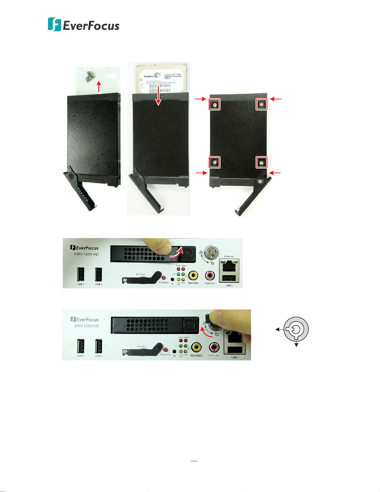
4. Take out the supplied HDD screw pack inside the HDD Tray, insert a HDD in the HDD Tray and
then screw the HDD to the tray with the supplied 8 screws.
5. Insert the HDD Tray into the drive bay and close the Locking Arm until you hear a click.
6. Lock the HDD Tray before you power on the mobile DVR.
13
EMV800 HD / EMV1200 HD Mobile DVR
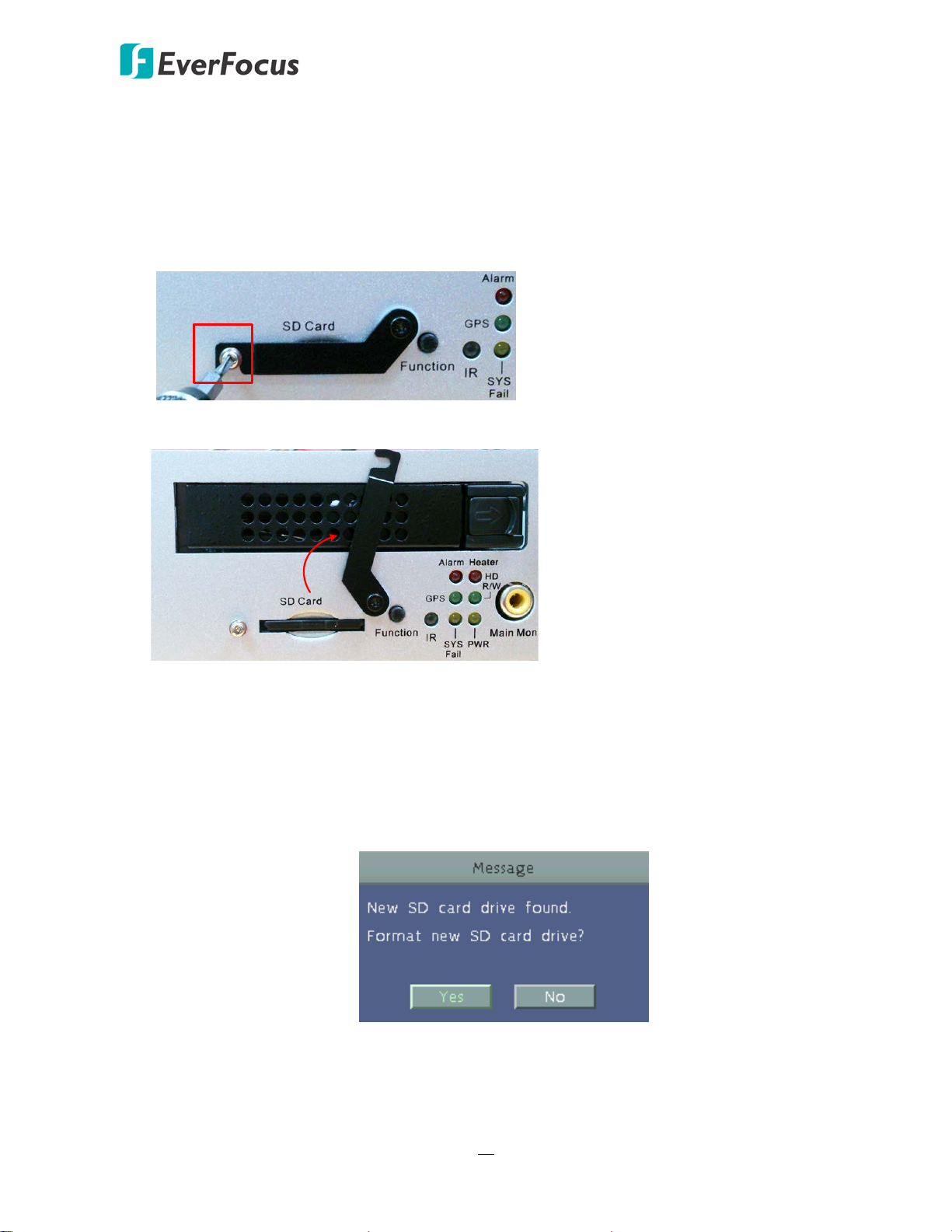
2.3 SD Card Installation
The mobile DVRs provide SD card function for Alarm event backup recording. Please follow the
steps below to install the SD Card. Up to 32 GB SD / SDHC cards are supported (see Appendix G
Tested Card Brands).
1. On the front panel of the mobile DVR, unscrew the SD card protection plate.
2. Lift up the SD card protection plate and then insert a SD card.
3. Screw back the SD card protection plate. The SD card installation is now complete.
The Mobile DVR will automatically detect when a new SD card has been inserted and the below
SD card format message will pop-up. Click Yes to format the SD card. The formatting process will
take about 30 ~ 60 seconds. Note that only the formatted SD card can be used for alarm event
backup recording function.
14
EMV800 HD / EMV1200 HD Mobile DVR
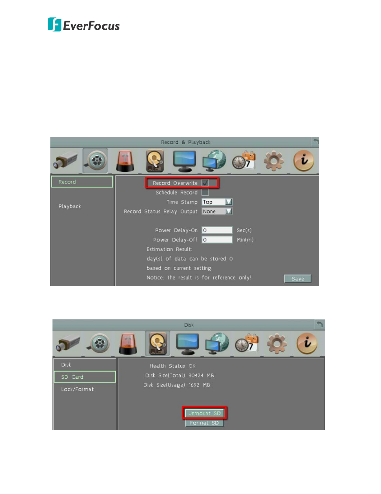
After installing the SD Card, it’s recommended to enable the Record Overwrite function. The
Record Overwrite function enables the mobile DVR to overwrite the recordings when the card
space is full. If Record Overwrite is not enabled, the alarm event backup recording to the SD card
will stop when card space is full. The mobile DVR will automatically pop-up a “SD Card Disk Full”
message for notification. Users will have to replace a new SD card; or backup the SD card
recordings and then erase (format) the recordings to resume the alarm event backup recording
function.
To enable the Record Overwrite function, please go to the OSD menu: System < Record &
Playback < Record.
To remove the SD card, please go to the OSD menu: System < Disk < SD Card, and click the
Unmount SD button. Then you can safely remove the SD card from the mobile DVR.
15
EMV800 HD / EMV1200 HD Mobile DVR
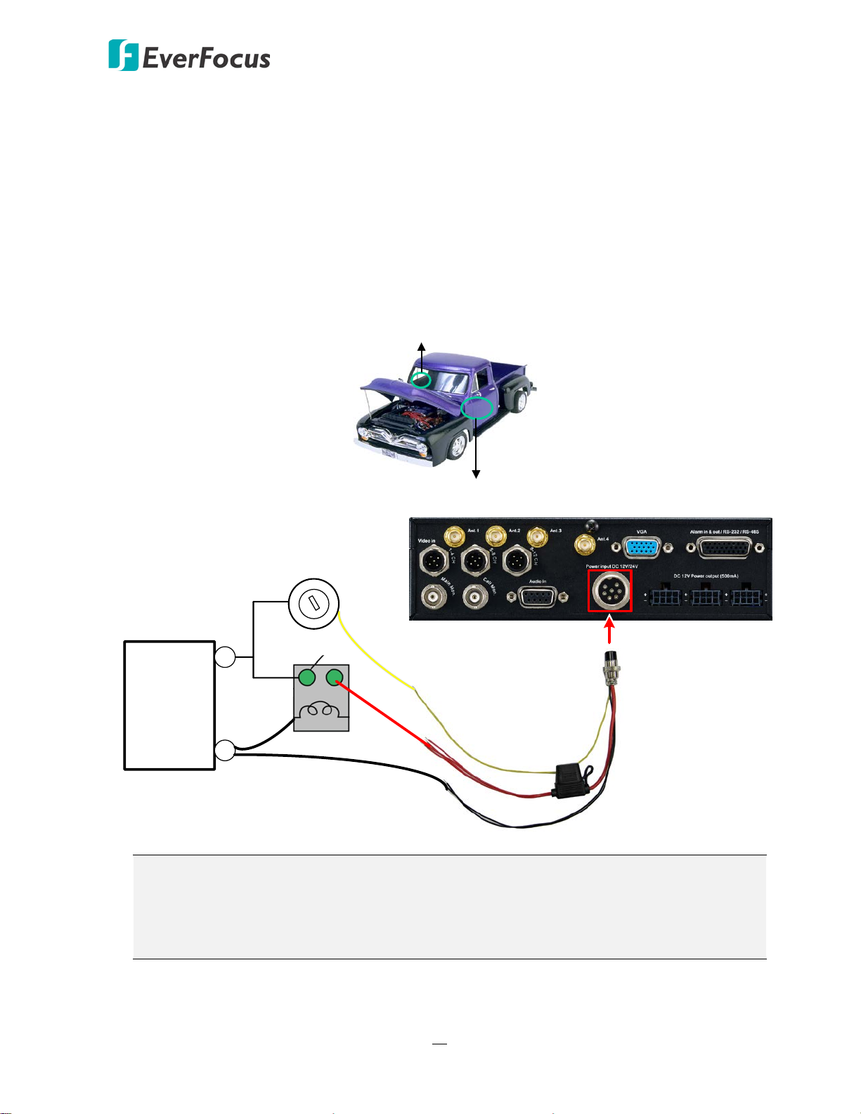
24V+ (Red)
IGN (Yellow)
Relay (24V)
EMV1200 HD (Rear Panel)
GND (Black)
Vehicle Battery
+
-
24V
Power Harness Cable
Fuse (15A)
Lock
ACC
On
Power
ACC
2.4 Vehicle Connection
The mobile DVR supports input power voltage between 9 VDC ~ 36 VDC. You can install the
mobile DVR in all kinds of vehicles support the above power voltage. The diagrams below are
examples to illustrate the connection inside car / truck with 12 VDC / 24 VDC.
* The following figures are using EMV1200 HD for example; the differences among the three
models are the video input / audio input / power output numbers.
2.4.1 Connecting to a Truck with 24 VDC
Glove box (inside or underneath)
Driver’s seat (between the seat and the back panel) or underneath the Passenger seat
Note:
1. If the car is without an ignition key, please connect the IGN (yellow) wire directly or
via a switch to the vehicle battery.
2. It is suggested to use a relay in the installation. Otherwise, the mobile DVR will always
draw the power from the vehicle battery.
16
EMV800 HD / EMV1200 HD Mobile DVR
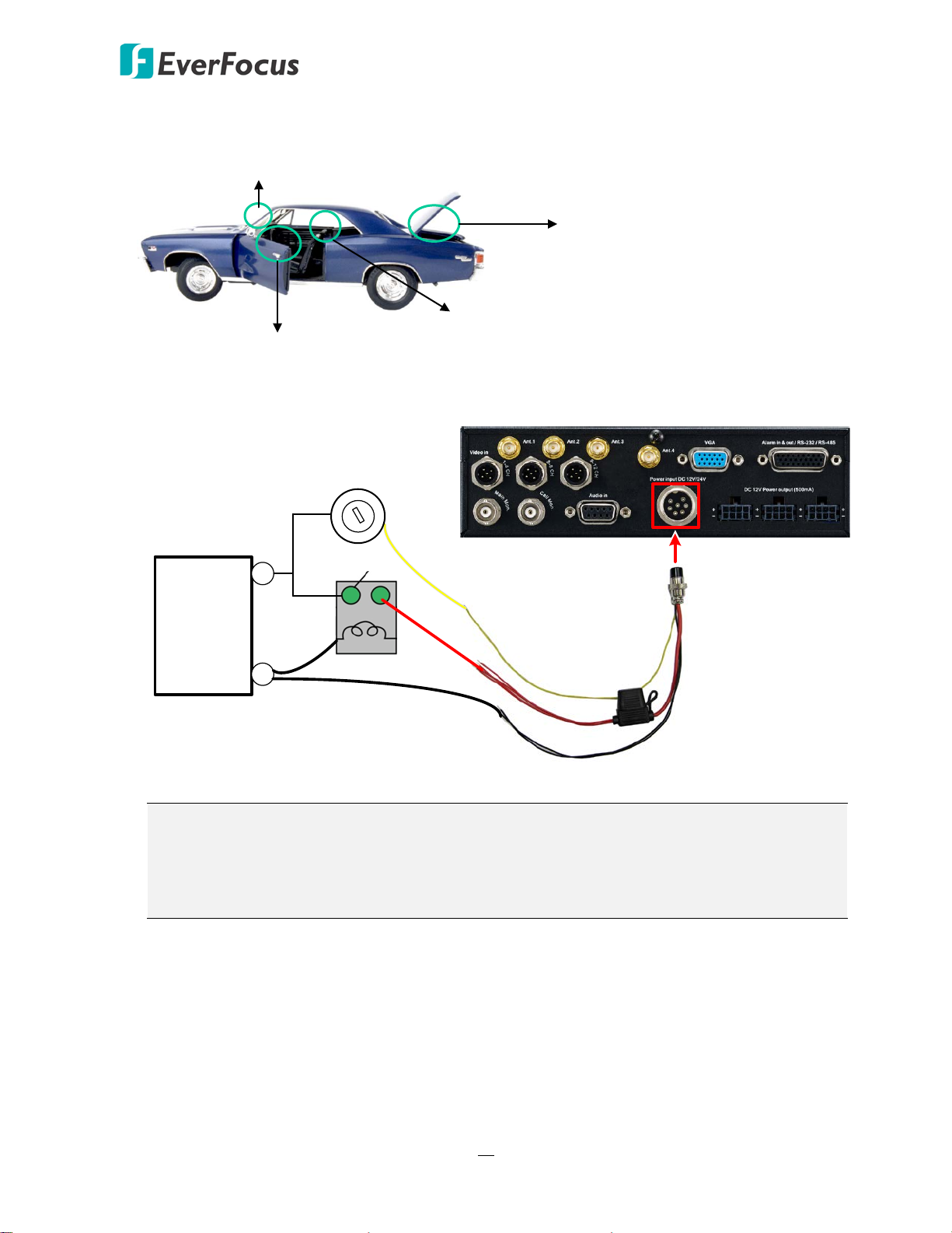
12V+ (Red)
IGN (Yellow)
Relay (12V)
GND (Black)
Vehicle Battery
+
-
12V
Power Harness Cable
Fuse (15A)
Lock
ACC
On
Power
ACC
EMV1200 HD (Rear Panel)
2.4.2 Connecting to a Car with 12 VDC
Glove box (inside or underneath)
Driver seat (between the seat and side panel)
Trunk
Passenger seat (underneath)
Note:
1. If the car is without an ignition key, please connect the IGN (yellow) wire directly or
via a switch to the vehicle battery.
2. It is suggested to use a relay in the installation. Otherwise, the mobile DVR will always
draw the power from the vehicle battery.
17
EMV800 HD / EMV1200 HD Mobile DVR
Front View Rear View
Mouse
2.5" HDD
1
2
Main Monitor
3 4
Speaker
WAN
CMS (Client PC)
5
9
Power Supply
Power Harness Cable
Analog SD/HD
Camera
Video Cable
6 8
Audio Cable
Audio Input
7
NB / PC
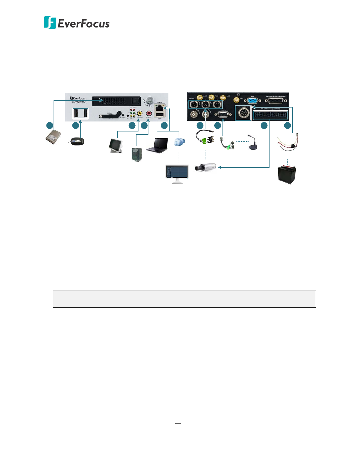
2.5 Basic Connection
After installing the mobile DVR in the vehicle, you can start connecting the mobile DVR to the
external devices. The instructions below describe the basic connection to the mobile DVRs. For
details on cable connections, please refer to the following sections.
1. To record videos, insert a 2.5” HDD to the HDD tray. Remember to lock the HDD Key Lock
after inserting the HDD or the recording will not start (see 2.2 Hard Disk Installation).
2. To control the system, connect a mouse to the mobile DVR or use the supplied IR Remote
Control.
3. To view videos, connect a monitor to the RCA port using the RCA cable supplied by the
monitor manufacturer. You can also connect other video out ports, please refer to 2.5
Monitor Connection.
4. To listen to audio of video source, connect a speaker to the Audio-out RCA socket. Note that
the speaker with a (built-in) amplifier and external power is required.
5. To manage the mobile DVR over network, use a standard RJ-45 cable to connect the mobile
DVR to the network.
Note: The mobile DVRs feature Wi-Fi/3G/4G function. You can optionally connect
Wi-Fi/3G/4G module and antenna to the mobile DVR for networking.
6. Connect the cameras to the mobile DVR using the supplied Video Cable. Please refer to 2.4.2
Video Cable / Power-Out Cable. (Note HD-TVI/HD-CVI/HD-SDI cameras are not supported.)
7. To power on the cameras, connect the power inputs of the cameras to the 12VDC power
outputs of the mobile DVR using the supplied Power-Out Cable, please refer to 2.4.2 Video
Cable / Power-Out Cable.
8. Connect the audio input devices to the mobile DVR using the supplied Audio Cable. Please
refer to 2.4.3 Audio Cable.
9. Connect the supplied Power Harness Cable to the power supply in the vehicle for powering
the mobile DVR. For details on vehicle connection, please refer to 2.3 Vehicle Connection.
18
EMV800 HD / EMV1200 HD Mobile DVR
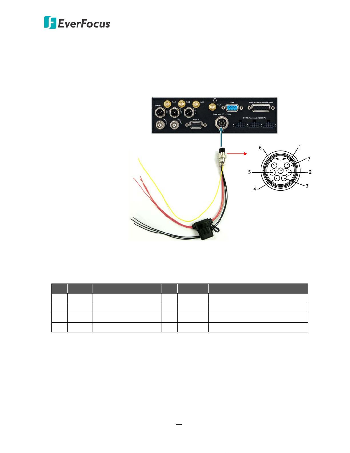
IGN (Yellow)
DC Power In (Red)
GND (Black)
9 VDC ~ 36 VDC
Pins on Power Cable
Power Input
EMV1200 HD (Rear Panel)
Power Harness Cable
2.5.1 Power Harness Cable
You can connect the mobile DVR to a power source between 9 VDC ~ 36 VDC.
(The following figure uses EMV1200 HD as an example).
Pin Assignment
No. Color Description No. Color Description
1 Red DC Power Input 5 Black GND
2 Red DC Power Input 6 Black GND
3 Red DC Power Input 7 Yellow IGN
4 Black GND
19
EMV800 HD / EMV1200 HD Mobile DVR
EMV1200 HD (Rear Panel)
Video Input
Ports
Camera 5 ~ 8
Video Cable
Camera 1 ~ 4
Video Cable
Camera 9 ~ 12
Video Cable
Power-Out
Cable
1 ~ 12
+ (black with white stripe)
- (black)
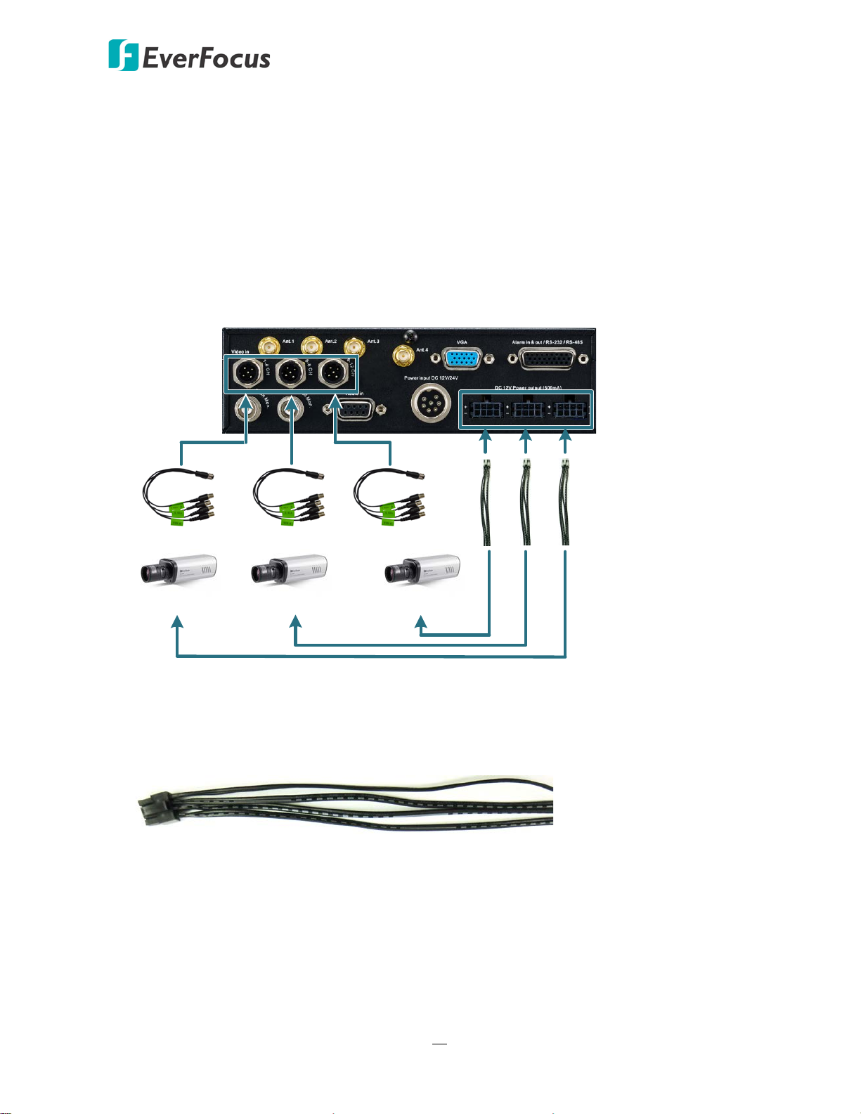
2.5.2 Video Cable / Power-Out Cable
The mobile DVRs have 1 / 2 / 3 Video In ports for connecting 4 / 8 / 12 analog cameras using
the supplied Video Cables. (Note that HD-TVI / HD-CVI / HD-SDI cameras are not supported.)
The Video Cables are all labeled with VIN 1~ VIN 4, and you can connect any Video Cable to
any of the Video In ports on the mobile DVR. If the Video Cable connects to 5-8 CH Video In
port, the cable labeled as VIN 1 will be channel 5 and so forth.
(The following figure uses EMV1200 HD as an example).
You can also use the supplied Power-Out Cable to power on the connected cameras. One
Power-Out Cable provides four set of power output wires (+/-). Each set of power output
wires provides 12VDC, 500mA power.
20
 Loading...