

Page 1
User Manual
E
MVV440000
E
M
DVV
D
R
R
Page 2

EVERFOCUS ELECTRONICS CORPORATION
EMV400 DVR
Instruction Manual
2010 EverFocus Electronics Corp
www.everfocus.com
All rights reserved. No part of the contents of this manual may be reproduced or transmitted in any form or by
any means without written permission of the Everfocus Electronics Corporation.
Release Date: Oct. 2010
QuickTime is a registered trademark of the Apple Computer, Inc.
Windows is a registered trademark of the Microsoft Corporation.
Linksys is a registered trademark of the Linksys Corporation.
D-Link is a registered trademark of the D-Link Corporation.
DynDNS is a registered trademark of the DynDNS.org Corporation.
Other product and company names mentioned herein may be the trademarks of their respective owners.
Page 3

Safety Precautions
Refer all work related to the installation of this product to qualified service personnel or system
installers.
Do not block the ventilation openings or slots on the cover.
Do not drop metallic parts through slots. This could permanently damage the appliance. Turn the
power off immediately and contact qualified service personnel for service.
Do not attempt to disassemble the appliance. To prevent electric shock, do not remove screws or
covers. There are no user-serviceable parts inside. Contact qualified service personnel for
maintenance. Handle the appliance with care. Do not strike or shake, as this may damage the
appliance.
Do not expose the appliance to water or moisture, nor try to operate it in wet areas. Do take immediate
action if the appliance becomes wet. Turn the power off and refer servicing to qualified service
personnel. Moisture may damage the appliance and also may cause electric shock.
Do not use strong or abrasive detergents when cleaning the appliance body. Use a dry cloth to clean
the appliance when it is dirty. When the dirt is hard to remove, use a mild detergent and wipe gently.
Do not overload outlets and extension cords as this may result in a risk of fire or electric shock.
Do not operate the appliance beyond its specified temperature, humidity or power source ratings. Do
not use the appliance in an extreme environment where high temperature or high humidity exists. Use
the DVR at indoor type temperatures within -20℃~55℃ (-4F~131ºF). The input power source for this
device is 10V~36VDC.
Read Instructions
All the safety and operating instructions should be read before the unit is operated.
Retain Instructions
The safety and operating instructions should be retained for future reference.
Heed Warnings
All warnings on the unit and in the operating instructions should be adhered to.
Follow Instructions
All operating and use instructions should be followed.
Cleaning
Unplug the unit from the outlet before cleaning. Do not use liquid cleaners, abrasive or aerosol
cleaners. Use a damp cloth for cleaning
ii
Page 4
y
Attachments
Do not use attachments not recommended by the product manufacturer as they may cause hazards.
Water and Moisture
Do not use this unit near water-for example, near a bath tub, wash bowl, kitchen sink, or laundry tub,
in a wet basement, near a swimming pool, in an unprotected outdoor installation, or any area which is
classified as a wet location.
Servicing
Do not attempt to service this unit by yourself as opening or removing covers may expose you to
dangerous voltage or other hazards. Refer all servicing to qualified service personnel.
Power Cord Protection
Power supply cords should be routed so that they are not likely to be walked on or pinched by items
placed upon or against them, playing particular attention to cords and plugs, convenience receptacles,
and the point where they exit from the appliance.
Object and Liquid Entry
Never push objects of any kind into this unit through openings as they may touch dangerous voltage
points or short-out parts that could result in a fire or electric shock. Never spill liquid of any kind on the
unit.
ATTENTION! This is a class A product which may cause radio interference in a domestic environment; in
this case, the user ma
be urged to take adequate measures.
Federal Communication Commission Interference Statement
This equipment has been tested and found to comply with the limits for a Class B digital device, pursuant to
Part 15 of the FCC Rules. These limits are designed to provide reasonable protection against harmful
interference in a residential installation. This equipment generates, uses and can radiate radio frequency
energy and, if not installed and used in accordance with the instructions, may cause harmful interference to
radio communications. However, there is no guarantee that interference will not occur in a particular
installation. If this equipment does cause harmful interference to radio or television reception, which can be
determined by turning the equipment off and on, the user is encouraged to try to correct the interference by
one of the following measures :
•Reorient or relocate the receiving antenna.
•Increase the separation between the equipment and receiver.
•Connect the equipment into an outlet on a circuit different from that to which the receiver is connected.
•Consult the dealer or an experienced radio/TV technician for help.
FCC Caution: Any changes or modifications not expressly approved by the party responsible for compliance
could void the users’ authority to operate this equipment.
iii
Page 5
WEEE
This Product is RoHS compliant.
The information in this manual was current upon publication. The manufacturer reserves the right to revise and improve his products.
Therefore, all specifications are subject to change without prior notice. Manufacturer is not responsible for misprints or typographical
errors.
Please read this manual carefully before installing and using this unit. Be sure to keep it handy for later reference.
iv
Page 6

TABLE OF CONTENTS
1 PRODUCT OVERVIEW..................................................................................................... 1
1.1 FEATURES....................................................................................................................... 1
1.2 PACKAGE CONTENTS................................................................................................... 2
1.3 SPECIFICATIONS ........................................................................................................... 3
1.4 FRONT
1.5 REAR
1.6 SYSTEM CONNECTION................................................................................................. 9
1.7 REAR PANEL CONNECTOR........................................................................................ 10
1.8 INSTALLATION OF EMV400 ...................................................................................... 12
1.9 VIDEO INPUTS/OUTPUTS INSTALLATION............................................................. 17
1.10 AUDIO INSTALLATION............................................................................................ 17
1.11 ALARM CONTACTS INSTALLATION .................................................................... 17
1.11.1 Alarm Input Contacts ........................................................................................................... .................18
1.11.2 Alarm Output Relay...............................................................................................................................18
1.12 USB-MOUSE INSTALLATION.......................................................................................... 18
1.13 NETWORK CONNECTION........................................................................................ 18
1.13.1 Direct PC Connection through Crossover Network Cable ...................................................................19
1.13.2 Network Connection through Patch Cable............................................................................................19
1.14 FINAL INSTALL PROCESS....................................................................................... 20
PANEL ................................................................................................................ 5
PANEL................................................................................................................... 7
2 MOUSE OPERATION....................................................................................................... 21
2.1 GENERAL USB MOUSE OPERATION....................................................................... 21
2.1.1 How to select a channel.........................................................................................................................21
2.1.2 OSD Root Menu.....................................................................................................................................21
2.1.3 Field Input Options ...............................................................................................................................22
3 CONFIGURATION
............................................................................................................ 23
3.1 CONFIGURATION OF DVR......................................................................................... 23
3.2 LOGIN............................................................................................................................. 23
3.3 ON SCREEN CONFIGURATION MENU ................................................................................ 24
3.4 SEARCH ......................................................................................................................... 26
3.4.1 Time Search...........................................................................................................................................26
3.4.2 G Sensor Search....................................................................................................................................27
3.4.3 GPS Speed Search.................................................................................................................................28
3.4.4 Event Search..........................................................................................................................................30
3.5 ARCHIVE
4 DVR CONFIGURATI
4.1 C
ONFIGURATION MENU.................................................................................................... 33
(USB)............................................................................................................ 32
ON.................................................................................................. 33
4.2 CAMERA SETTING ...................................................................................................... 35
4.2.1 Normal...................................................................................................................................................35
v
Page 7

4.2.2 Video Adjust ..........................................................................................................................................36
4.2.3 Alarm .....................................................................................................................................................37
4.3 RECORD SETTING ....................................................................................................... 38
4.3.1 Record...................................................................................................................................................38
4.4 ALARM/GPS .................................................................................................................. 39
4.4.1 Alarm-Alarm Settings............................................................................................................................39
4.4.2 Alarm-Event Settings.............................................................................................................................41
4.4.3 Alarm – Video Loss...............................................................................................................................50
4.4.4 Alarm-G-Sensor Settings.......................................................................................................................52
4.4.5 Alarm-GPS Speed..................................................................................................................................53
4.4.6 Alarm-GPS Event Action.......................................................................................................................54
4.4.7 Alarm-GPS Fencing..............................................................................................................................55
4.5 DATE/TIME SETTING ........................................................................................................ 56
4.5.1 Date/Time Settings ................................................................................................................................56
4.5.2 Daylight Saving.....................................................................................................................................57
4.6 D
4.6.1 Title .......................................................................................................................................................58
4.6.2 Monitor On Screen Display................................................................................................................... 58
4.6.3 Layout....................................................................................................................................................60
4.6.4 Sequence................................................................................................................................................61
ISPLAY ........................................................................................................................... 58
4.7 NETWORK SETTING.................................................................................................... 62
4.7.1 LAN Settings..........................................................................................................................................62
4.7.2 Wireless Settings....................................................................................................................................65
4.7.3 Mobile Connection Settings...................................................................................................................66
4.7.4 Email Settings........................................................................................................................................ 67
4.7.5 DDNS Settings.......................................................................................................................................68
4.7.6 Alarm Server Settings............................................................................................................................70
4.8 SYSTEM ......................................................................................................................... 71
4.8.1 User.......................................................................................................................................................71
4.8.2 I/O Control............................................................................................................................................74
4.8.3 DISK Info...............................................................................................................................................77
4.8.4 LOG.......................................................................................................................................................78
4.8.5 SETTINGS.............................................................................................................................................80
4.8.6 SERVICE...............................................................................................................................................81
4.9 INFORMATION............................................................................................................. 82
5 NETWORKING OVERVIEW
.......................................................................................... 83
5.1 INTRODUCTION TO TCP/IP............................................................................................... 83
5.2 S
UBNET MASKS................................................................................................................ 83
5.3 GATEWAY ADDRESS......................................................................................................... 83
5.4 V
IRTUAL PORTS................................................................................................................ 84
5.5 PRE-INSTALLATION .......................................................................................................... 84
5.6 WHAT IS YOUR NETWORK SETUP?.................................................................................... 85
5.7 S
IMPLE ONE TO ONE CONNECTION................................................................................... 86
5.8 DIRECT HIGH SPEED MODEM CONNECTION ..................................................................... 91
5.9 ROUTER OR LAN CONNECTION........................................................................................ 93
6 REMOTE OPERATION FROM BROWSER...................................................................... 96
6.1 CONNECTING TO EMV400......................................................................................... 96
vi
Page 8

6.2 BROWSER SECURITY SETTING .................................................................................... 97
6.2.1 Installing ActiveX controls....................................................................................................................97
6.2.2 Enabling ActiveX Controls..................................................................................................................100
6.3 REMOTE LIVE VIEW................................................................................................. 103
6.4 REMOTE PLAYBACK................................................................................................ 105
7 EVERFOCUS DDNS SETUP.......................................................................................... 106
8 LINKSYS & D-LINK PORT FORWARDING ............................................................. 108
8.1 TYPICAL LINKSYS PORT FORWARDING............................................................. 108
8.2 TYPICAL
D-LINK PORT FORWARDING ................................................................ 110
9 TROUBLESHOOTING
................................................................................................... 113
APPENDIX A: TIMING OF ALARM MODES.................................................................... 115
APPENDIX B: EXPRESS SETUP RECORDING VALUE SELECTION RULES .......... 118
APPENDIX C: REMOTE CONTROL................................................................................... 120
vii
Page 9

Chapter
1
1 PRODUCT O VERVIEW
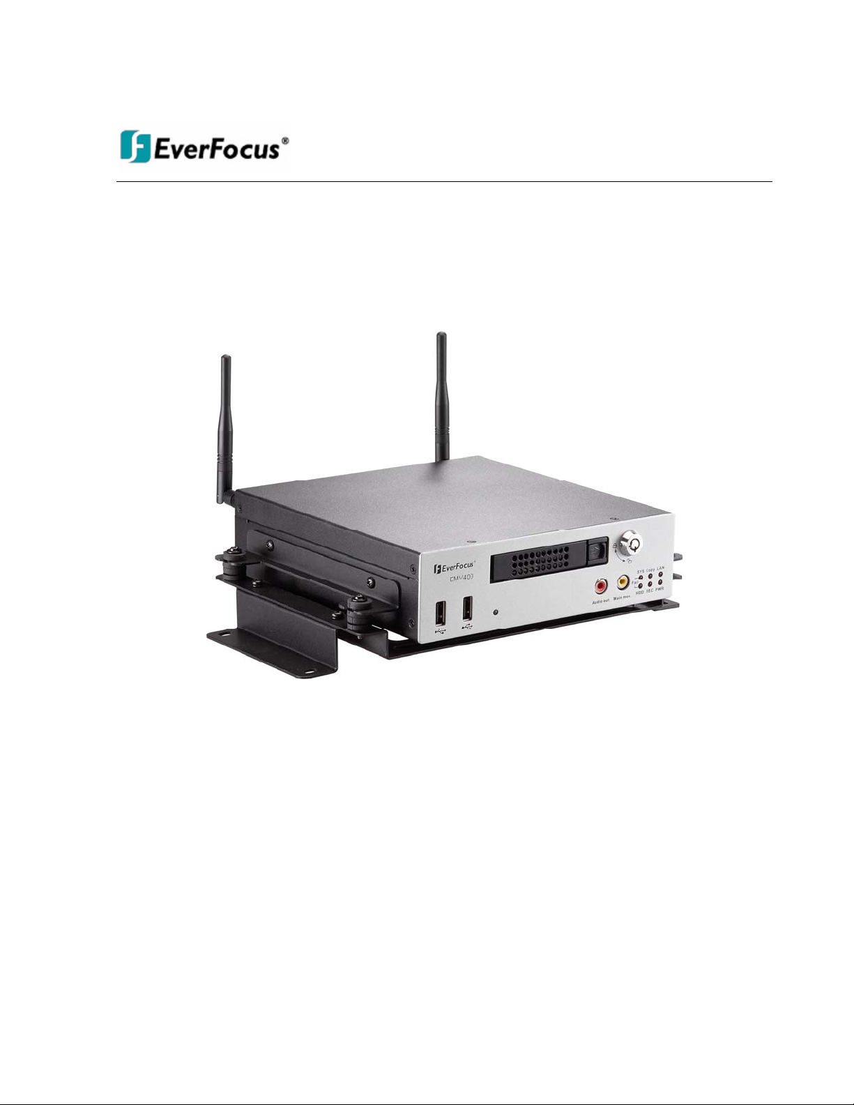
Full featured video surveillance on the move: the EverFocus EMV400 digital video recorder, with H.264
compression technology for enhanced recording capacity and improved network image transmission speed
with high image quality, delivers real-time video and audio recoding on all 4 channels (120FPS @ 2CIF/
60fps @ D1 resolution, frame rate and resolution independently configurable for each camera). The DVR
provides multiple interfaces including 3 USB ports, RS-485, RS-232, GPS port, wired and WiFi Ethernet, IR
remote control, 6 alarm inputs and 2 alarm outputs. Video outputs are provided at both front and rear
panels for ease of installation and maintenance, plus the new easy to read graphical user interface is
specially designed for use with portable small-screen monitors. The power supply in the EMV400 provides
surge protection, voltage regulation, and programmable delay power on/off for the DVR and the system
cameras. Added to this, comprehensive features including hot swap hard drive, embedded 3-axis g-sensor,
GPS receiver interface, 802.11b/g WiFi, individual camera power outputs, remote control capability and
shock/vibration resistant locking Molex connectors make this DVR the best choice for your 1~4 channel
portable and mobile recording applications.
1.1 FEA TU RES
4Channels of video and audio recording
1-DIN car audio size
Recording Rate : 60fps @ D1 resolution / 120fps @ 2CIF or CIF resolution (with global settings;
record rate, resolution and quality can be set independently per-camera up to the maximum of 240
CIF-equivalent FPS)
H.264 compression format for efficient disk and network utilization
Front and rear panel video outputs for easy connection and configuration
Special Graphical User Interface design for use with mobile small- sized monitors
Molex connectors for shock & vibration resistance; interface cables to BNC, RCA and power jack s
supplied
Alarm Inputs & Outputs : 6 & 2 (alarm outputs are form “C”)
Embedded 3-axis g-sensor function with separate programmable alarm levels for X/Y and Z axis
Supports single 2.5” SATA hard disk standard (up to 1TB)
Supports multiple interfaces: 3xUSB , RS-485, RS-232, GPS port, wired Ethernet, IR Remote Control
Optional wireless 802.11 b/g with diversity antennas
Provides camera power for 4 cameras; interface cables to power jacks supplied
Optional External EDGE/GPRS/CDMA/WI-FI Modules for cellular/specialized wireless Transmission
GPS function tracks speed and geographic limits (optional external GPS receiver)
Power Supply : 10V~36VDC with Surge Protection, Voltage Regulator, programmable Delay on/off
1
Page 10

Temperature : -20ºC ~ 55ºC (Operating), -20ºC ~ 85ºC (Non-Operating)
1.2 PA CKA GE CONTENTS
- Digital Video Recorder x1
- HDD Tray x 1
- HDD Fixing Bracket x 1 set
- Screws x 1 pack
- Antenna x 1 set
- IR Remote Control x 1
- Battery x 2
- Camera Power cable x 3
- Video & Audio cable x 3
- Alarm cable x 1
- Alarm Output cable x 1
- RS232/RS485 cable x 1
- GPS cable x 1
- DVR power cord x 1
2
Page 11

1.3 SPECIFICA TIO NS
EMV400 - 4CH Mobile DVR
Video Format NTSC/PAL (auto detected by system)
Operating System Embedded Linux with special small monitor friendly GUI
Video Input 4 channels (vibration resistant locking Molex connectors – Interface
cables to BNC-F supplied: two groups of 2 cameras each)
Video Output Main monitor: 1 composite BNC rear panel / 1 front panel RCA
output
Video Compression H.264
Recording Resolutions NTSC: 720x480/720x240/360x240
PAL: 720x576/720x288/360x288
Audio Inputs 4 line in (vibration resistant locking Molex connectors - Interface
cables to RCA-F supplied: two groups of 2 cameras each)
Audio Outputs 1 front panel RCA line out
Alarm Inputs 6 alarm inputs (vibration resistant locking Molex connectors -
Interface cables supplied)
Alarm Outputs 2 alarm outputs (form “C”; contacts rated at 30V AC/DC @ 1 amp –
interface cables supplied)
Storage 2.5" HDD x 1(up to 1TB)
Recording Rate
NTSC: D1 60FPS, 2CIF 120f FPS, CIF 240 FPS
PAL: D1 50 FPS, 2CIF 100 FPS, CIF 200 FPS
Per camera resolutions and record rates can be set individually per
camera through the OSD menus up to the maximum record
capacity of 240 NTSC (200 PAL) CIF equivalent FPS
Recording Mode Continuous recording, event recording, continuous + event
recording
(Rate and resolution in each mode set independently per camera)
Record Quality Adjustable in five levels per camera per Record Mode
Pre Alarm Recording Optional; 5 second interval
Playback Rate NTSC: D1 60 FPS, 2CIF 120 FPS, CIF 240 FPS
PAL: D1 50 FPS, 2CIF 100 FPS, CIF 200 FPS
Playback Search Time/date, event search
Video Loss Detection Yes
Event Alarm Fan failure, hard disk temperature, hard disk failure, hard disk full,
hard disk removed, power loss (after power is restored), network
loss, GPS loss, GPS speed, GPS fencing, G sensor limits
3
Page 12

Email alert Multiple email notifications in response to alarms and events.
(Requires real time network connectivity though cellular or WiFi
service).
G Sensor Embedded 3-axis G Sensor; data recorded; alarm if separate user
limits for X/Y or Z axis exceeded
GPS Function Optional External GPS Sensor for speed and geographic limit
alarms (rectangular or circular fencing)
Configuration Method On screen menu with ‘portable monitor friendly’ graphical user
interface
Control/Setup IR remote control, USB mouse, network I/F
Real time clock Can be synchronized to GPS/NTP time source; flexible DST
settings
Watchdog Function Reboots DVR automatically if required
Networking RJ45 socket, 10/100Mbps; 802.11b/g WiFi with diversity antennas
TCP-IP/DHCP/PPPoE/DDNS/SMTP/SSL/POP3/HTTP/NTP
System Warnings System fail LED : HDD full, HDD/Sys Temp, Fan fail,
HDD fail LED : HDD power off, HDD failure
File Export USB 2.0 interface
Interfaces RS-232 x 2, RS-485, USB x 3, GPS port
Power Source 13.8VDC nominal; 10V~36VDC range (Built in surge protection,
voltage regulation, programmable Delay On/Off relative to ignition
or other switched voltage)
Total current 5.5 amps @ 12VDC with 4ch x 450mA cameras
Camera Power Outputs 900mA for camera 1~2 and 900mA for camera 3~4. Vibration
resistant locking Molex connectors – interface cable provided to
coaxial power plugs: 2 X groups of 2 cameras.
Dimensions DVR alone : 178 x 50 x 199mm / 7”x 2”x 7.8”(1-DIN size)
DVR in mount with antennas 272 x 145 x 224mm / 10.7”x 5.7”x
8.8”
Weight DVR without mount 1.7kg / 3.75lbs.
DVR with mount 2.15kg / 4.74lbs
Operating Temp.
Working Temperature: -20℃~55℃; -4F~131ºF
Storage Temperature: -20℃~85℃; -4F~185ºF
4
Page 13
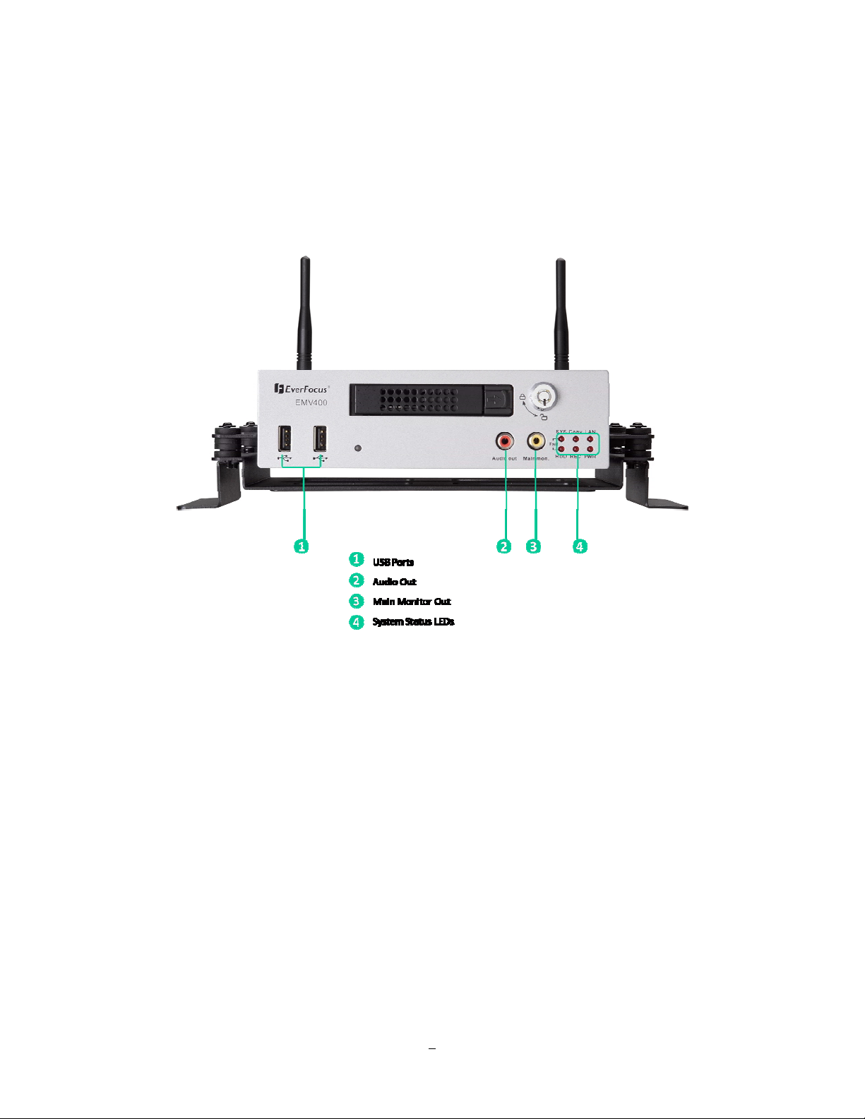
1.4 FRONT PANEL
Your primary interaction with your new DVR will be through the Front Panel buttons and their
corresponding buttons on the included IR Remote Control. Take a moment to learn where the keys are as
the remainder of the manual will refer to them often.
Figure 1-1 Front Panel
1) USB 2.0: For connecting USB-Flash-Drive to copy/archive video or for firmware upgrades.
2) Audio Out: Connect to the line level input of an audio amplifier
panel, no conflict between these 2 outputs, they both can be connected simultaneously).
(same output as the audio out at rear
3) Main Monitor Out: Main monitor for live and playback display and on-screen display. (same output as
the main monitor out at rear panel, no conflict between these 2 outputs, they both can be
connected simultaneously).
4) System Status LEDs: Indicators system status.
System fail LED: HDD full, HDD/System Temperature, Fan fail
HDD fail LED: HDD power off, HDD failure
Copy: This LED ON indicates system is archiving data.
5
Page 14

LAN: This LED ON indicates Network active. Network LED turns on depending on the network type
(LAN, Wireless or Mobile) set in Network setting.
Record: This LED ON indicates Record active.
Power: This LED ON indicates Power on.
6
Page 15
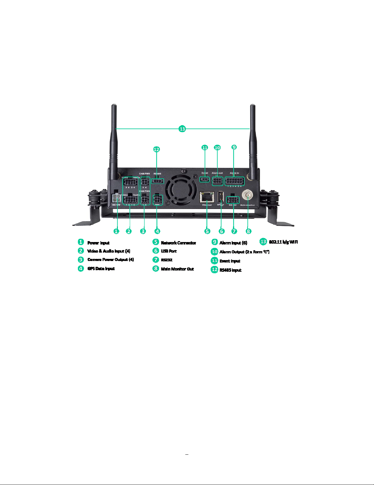
1.5 REAR PANEL
During initial setup you will be connecting your DVR to multiple input and output devices. This is done
through the rear panel.
Figure 1-2 Rear Panel
1
○
Power Input/Ignition Control In/Switched power out: 4 pins are reserved for power input; connect to
10V~36VDC power source. 1 pin is for ignition control; connect to the other vehicle devices to avoid
excess power consumption at ignition. 1 pin is reserved for switched power out. The power source
used for this additional power output is 600 mA x 12VDC.
2
○
Video & Audio Inputs (4): Connect camera’s video output or other composite video source to the video
input connection.
Connect line level output of an audio preamplifier to the audio input connection corresponding to the
appropriate camera.
3
○
Camera Power Outputs (4): EMV400 can provide power source to the cameras, connect camera
power to this output by using the camera power cable. The power source used is 450mA x 12VDC.
7
Page 16

4
○
GPS Data Input: Connect this connector to GPS receiver via GPS cable.
5
Network Connector: RJ-45 network connection 10/100Mbps Ethernet. There are two LEDs on the
○
LAN jack; Green LED means network is connected, amber LED flickers when data is
being exchanged.
6
○
USB port: USB port recommended for connecting the USB mouse.
7
○
RS232 socket: Connect this connector to RS232/RS485 compatible device.
8
○
Main Monitor Out: Main monitor for live and playback display and on-screen display. (same output as
the main monitor out at front panel, no conflict between these 2 outputs, they both can be
connected simultaneously)
○9 Alarm Input: Connect up to 4 alarm inputs, selectable between N.O./N.C. contacts.
10
○
Alarm Output: N.C or N.O type alarm out (form “C”).
11
○
Event Input: Reserved port.
12
○
RS485 Input: For remote control via RS-485 keyboards and telemetry control for attached PTZ devices.
13
○
802.11 b / g WiFi: Connection of the antenna.
8
Page 17
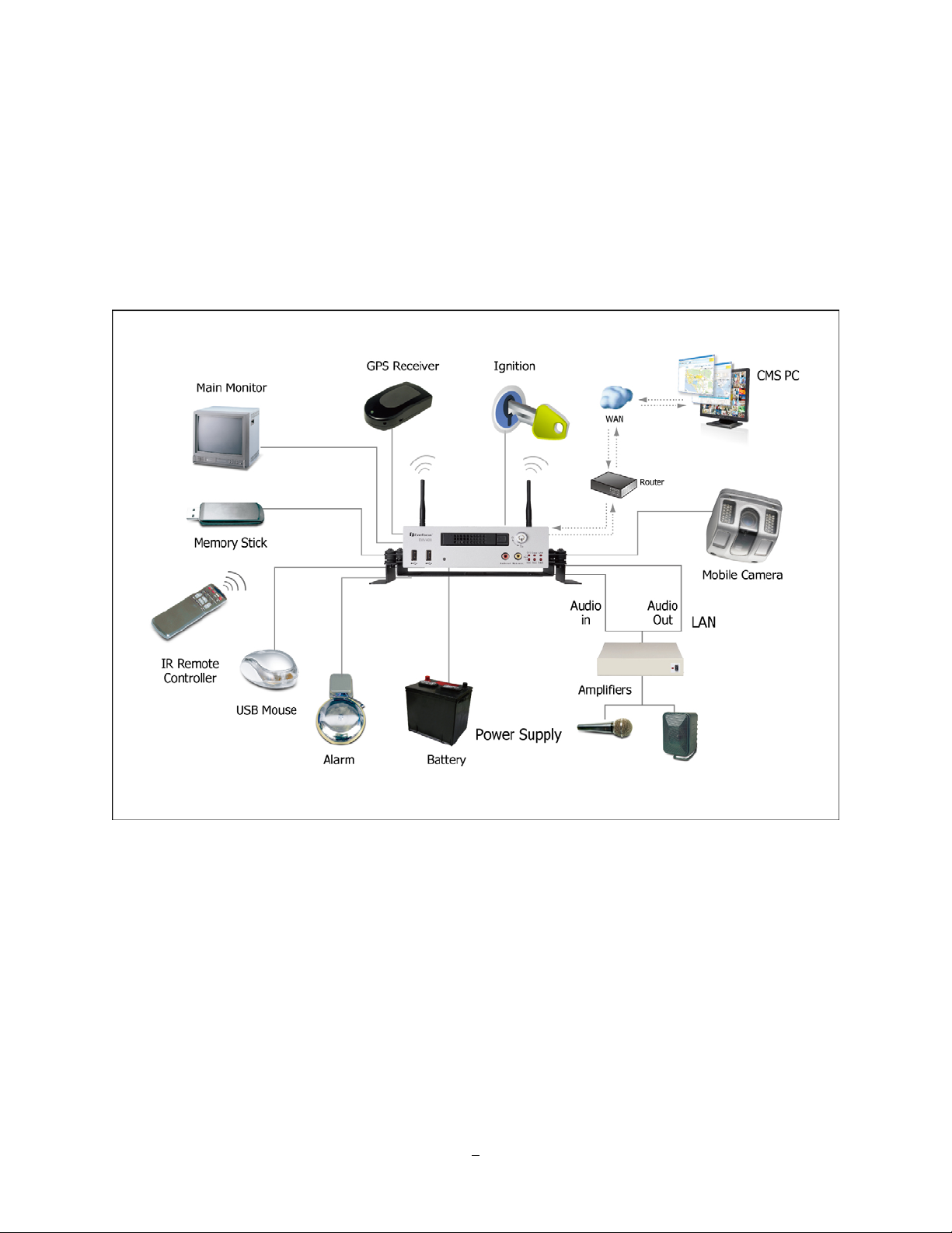
1.6 SY STEM CONNECTION
Please refer to the following diagrams for the system connections.
Note: Monitor and Camera must be purchased separately.
9
Page 18

1.7 REAR PANEL CONNECTOR
RS232/RS485
POWER
485+ 485- GND
IGN
GND
12V
ALARM IN
ALARM IN1 ALARM IN2 ALARM IN3 ALARM IN4 ALARM IN5 ALARM IN6
GND GND GND GND GND GND
ALARM
OUT
NO1 COM1 NC1
NO2 COM2 NC2
VIDEO/AUDIO IN1
VIDEO IN1 VIDEO IN2 VIDEO IN3 VIDEO IN4
GND GND GND GND
VIDEO/AUDIO IN2
VIDEO IN1 VIDEO IN2 VIDEO IN3 VIDEO IN4
GND GND GND GND
10
Page 19

CAM POWER1
CAM POWER2
12V OUT 12V OUT
GND GND
GPS
GND GPS_TX
GPS_RX +12V
12V OUT 12V OUT
GND GND
11
Page 20
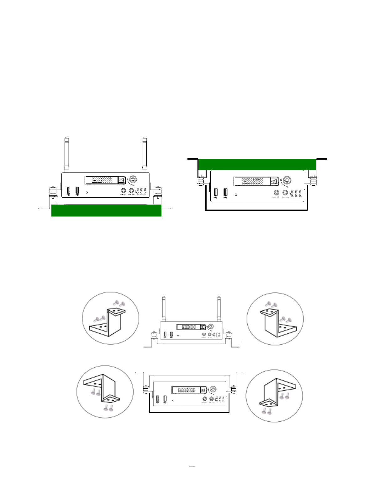
1.8 INST ALLATION OF EMV400
The DVR can be mounted horizontally (suspend or support mounted).
Support
Interface
Interface
Show all the possible ways to mount the DVR.
Use the two Z-brackets supplied to mount it in any ways shown.
Support
Support
Suspend
Suspend
12
Page 21

Quick Installation Guide
Unpack Everything
Make sure you have everything you need before you begin the installation.
Equipment Required
The following tools may help you to complete the installation:
‧Drill
‧Screwdrivers
‧Wire cutters
Choosing the Location Choose a location for installation that:
‧Provides convenient access for installing or removing the hard drive
‧Allows air to flow around the fan vents. Inadequate or improper air flow can impede proper operation of
the unit
Avoid any location for installation:
‧That is subject to high vibration
‧That is subject to high sunlight levels
‧That is subject to drenched of the rain
‧Where passengers can interfere with unit
‧Next to a heater duct
The following table lists the recommended location options.
Location Convenient operation Easy to install Low vibration Good air flow
Bottom of glove box- horizontal mount
Bottom of passenger seat next to the driver
Underneath bulkhead-horizontal mount
Front of bulkhead-horizontal mount
Beside deriver seat-horizontal mount
Yes
NO
Yes
Yes
Yes
Yes
Yes Yes
Yes
Yes
Yes
Yes
Yes
NO
Yes
Yes
Caution: Do not install the DVR on the floor or on the transmission access hatch. These locations
have the highest levels of vibration and may be subject to water damage.
Yes
Yes
Yes
Yes
13
Page 22

Possible Installation Locations Inside the Automobile Vehicle: Truck
Glove box (inside or underneath)
Drive seat (between seat and wall) or Passenger seat (underneath)
(Users are suggested to use “support” for mounting option)
Show the wiring on the wiring harness that connects to the electrical system.
14
Page 23

Possible Installation Locations Inside the Automobile Vehicle
Glove box (inside or underneath)
Trunk (Users are suggested to use
“suspend” for mounting option)
Passenger seat (underneath)
Drive seat (between seat and wall)
Show the wiring on the wiring harness that connects to the electrical system.
15
Page 24

Installing the Camera(s) and Monitor
The DVR is typically connected to one camera installed inside the car. Other camera(s) can also be
installed in different locations (for example, use the waterproof camera to the outside of vehicle). For
installation procedure, please refer to the guide that came with the camera(s) you purchased.
The Monitor power supply connects from the Automotive adapter (cigarette plug)
Monitor and cameras must be purchased separately.
LCD Monitor
LCD Monitor
Connect the Camera(s)Connect the power connector from the camera(s) harness into the CAMERA
POWER OUT jack on the back panel of the DVR.
Connect the primary camera(s) video connector to the CAMERA INPUT and the audio connector to the
AUDIO INPUT in the back panel.
Adjust the camera(s). After the camera is installed, connect a monitor directly to the camera and observe
the image.
Make any adjustment if necessary.
16
Page 25

1.9 VIDEO INPUTS/OUTPUTS INSTALLA TION
Cameras and CCTV monitors must use copper center conductor/copper braid 75 Ohm video cable (e.g.
RG-59, RG-6, RG-11) with BNC connectors.
To avoid impedance mismatch and undesired loss/reflections, 50 Ohm coax cable (e.g. RG-58), or 75 ohm
foil shield antenna cable and other types of coaxial cable are not compatible.
All connected video sources must provide a 1 Vpp NTSC or PAL standard video signal.
When converting other transmission types (twisted pair, fiber optics, radio) for the video inputs, be sure to
verify accurate receiver calibration and signal levels.
ATTENTION: In order for the system to auto-detect the appropriate video format (NTSC or PAL), make
sure that there is a video signal on video input 1 upon power-up.
1.10 AUDIO INSTALLA TION
This DVR provides 4 line level audio inputs and 1 line level audio output.
ATTENTION: The direct connection of a non-amplified microphone is not supported (a microphone
amplifier is required). The audio output requires an amplifier to drive a speaker or headphones.
The installation must be connected with audio coax cable and RCA plugs.
AUDIO RECORDING FUNCTIONALITY:
Audio recording is activated / deactivated in the Camera Menu for Camera #1~4 respectively. Please check
and always comply with local laws and regulations when using audio recording.
The audio channel is always recorded together with video and is independent of the image recording rate.
Though the audio record control is done in the Camera #1~4 screen, there is no specific camera allocation.
1.11 ALARM CONTA CTS INSTALLA TION
The alarm inputs can be used to start recording or for recording rate adjustment. In addition, alarm
reactions such as camera display on the monitor, buzzer, e-mail and network alarm are available. The
alarm output relay can be switched if required. Alarm input response actions can be controlled according to
a flexible schedule.
17
Page 26

1.11.1 Alarm Input Contacts
This DVR provides one alarm input per camera. All inputs are programmable N.O. (Normal Open) or N.C.
(Normal Closed) Inputs have to be switched by dry contacts.
Alarm input with N.O. (Normal Open) contact Alarm input with N.C. (Normal Closed) contact
in idle state in idle state
All settings are programmed in the ALARM menu (Section 0).
1.11.2 Alarm Output Relay
The relay output provides either Normally Open or Normally Closed dry contacts.
Output relay in idle state
1.12 USB-Mouse installation
Connect the USB mouse to one of the 2 USB ports. (This can be done while DVR is powered on) The rear
USB V1.0 port is recommended to reserve the higher speed front USB V2.0 port for video copy/export.
NOTE: Recommended mouse types are Logitech® and Microsoft® wired USB wheel-mouse. Wireless
USB mouse is not supported.
1.13 NETWORK CONNECTION
This section only describes physical connection to an Ethernet network. This step must be completed
before the DVR can connect to the network. There are two basic types of connection:
18
Page 27

1.13.1 Direct PC Connection through Crossover Network Cable
The point-to-point connection of DVR and PC requires a crossover (crossed) network cable. This type of
connection is ONLY used for direct connection to a single PC. Make sure that the PC is equipped with a
10/100 Mbps compatible network connection.
Figure 1-3 Direct PC Connection
Pinout of crossover-cable
1.13.2 Network Connection through Patch Cable
The connection to an existing network requires a normal patch cable (straight-through). The illustration
shows the connection to a network switch or router.
Figure 1-4 Network Connection through Patch Cable
19
Page 28

Pinout of straight patch cable
1.14 FINAL INST ALL PROCESS
Once you have completed the basic wiring connections, you are ready to turn on the DVR. Simply plug in
the power source. The POWER LED will light up if power is normal. Once the system has finished loading,
you can begin to set up the menu options for the DVR.
Note: When the DVR is placed in an environment where the temperature is under -10°, the DVR will NOT
turn on immediately. The heater will heat up the DVR until the temperature reaches -5°. The DVR will only
turn on when the temperature is above -5°.
20
Page 29

Chapter
2
2 MOUSE OPERA TION
EMV400 mobile DVRs support 2 sources to control the DVR. It can be controlled with a mouse and the
handheld IR remote control. (For IR remote control, please refer to Appendix C Remote Control)
This chapter will cover the basic operation using the mouse.
2.1 GENERAL USB MOUSE OPERA TION
2.1.1 How to select a channel
1. In a view consisting of more than one channel, users can select a channel by clicking once on the
desired channel screen. The selected screen will be highlighted by a white frame.
2. Double clicking on a channel screen will display full screen for this channel.
2.1.2 OSD Root Menu
1. Right-click the mouse to obtain the DVR Root menu (see Figure 2-1 OSD Root Menu ).
Figure 2-1 OSD Root Menu
21
Page 30

2. Click on any icon to perform that action. These actions are covered in detail in Chapter 3.
3. Click the button to go to live view.
2.1.3 Field Input Options
The following are examples of different types of fields available in the Configuration menu.
Textbox: Click on the box and an on-
screen keyboard will appear*. (see note about the on-screen keyboard below)
Dropdown box: Click on the down arrow to see all selections, then directly click on an
option to select it.
Check box: Click on the box to enable it (checked) or disable it (unchecked).
Button: Click the button to execute the function.
* Note about on-screen keyboard:
Click on a button to input that character.
The buttons on the right and bottom have the following functions:
Space Enter a space
Caps Switch to capital letters
Figure 2-2 On-Screen Keyboard
Delete the letter
/Del
Confirm the selection
Move to right
Move to left
22
Page 31

Chapter
3
3 CONFIGURA TION
This chapter provides information for configuring EMV400.
3.1 CONFIGURA TION OF DVR
EMV400 can be configured through On Screen Display Playback and Configuration
Connect to the “Main Mon” output with a monitor and use the mouse or the remote control to configure
menu settings.
3.2 LOGIN
In order to access EMV400 options, users may be asked to log in for authority identification. To log in,
follow these steps.
1. Right click on the screen to display the Main Menu
2. The following screen pops up:
Figure 3-1 Login page
3. Select the user name from the drop-down list and input the password. The defaults are:
User name: admin (lower case)
Password: 11111111
To input password: click the password field to bring up the on-screen keyboard (see Figure 3-2 On-screen
Keyboard). Click on each button to input the desired characters for the password. When finished, click
“
” on the on-screen keyboard to confirm the password.
+ Click on the “Login” button to log in to the system.
23
Page 32

Figure 3-2 On-screen Keyboard
3.3 On Screen Configuration Menu
1. To bring up the Main Menu, right-click with the USB mouse to bring up the root menu.
2. Left-click on the “Playback” icon “
shown below:
Figure 3-3 On-screen Configuration
” to enter the Playback Menu. A Playback Bar appear as
24
Page 33

Playback Bar Name Description
Layout TheEMV400 DVR has several display modes available. Click on the
desired layout choice
Display mode Press to show camera information, press again to show network,
HDD, GPS information. Press again to hide all information.
Audio Press to cycle through Audio 1, 2,3,4 or no audio
Fast Rewind Press to start fast reverse playback
Play Press to playback **
Fast Forward Press to start fast forward playback
Search Press to search by Time, Event, G Sensor or GPS. Please see “3.4
Search” for more details about search function.
Archive Press to save a video clip to USB. Please see “3.5 Archive” for more
details about archive function.
Exit Exit from playback bar
** During playback, DVR will stop recording. When an event occurred while playback, event log will be
saved but won’t display alarm status.
25
Page 34

3.4 SEARCH
Right-click to bring up the Root menu, select Playback and click to enter Search Menu.
3.4.1 Time Search
Figure 3-4 Search Menu – Time Search
Play From: Select the time to begin the search by choosing the Date and Time.
Click on the “Play” button to start the search. The DVR will automatically begin to play the video selected.
The DVR will play the nearest time if there is no data at the selected time.
In search playback mode, pressing the “Stop” button will return to the search menu.
Record Time (Start): Displays the starting time of record data in the disk.
Record Time (End): Displays the end time of record data in the disk.
Click
Click
button to enter GPS search menu.
button to enter G Sensor search menu.
Click button to enter Event search menu.
Click button to go to live view.
26
Page 35

3.4.2 G Sensor Search
Click
button to start G Sensor search.
Figure 3-5 Search Menu – G-Sensor Search
From: Select starting date and time
To: Select ending date and time.
Select search format from Less Than, More Than, Inside Range and Outside Range.
Value: Set the G-sensor value to be searched. If search format is a range, then set the values for both
ends of range.
Click button to start search action.
Click
button to enter GPS search menu.
Click button to enter Event search menu.
Click button to enter Time search menu.
Click
button to go to live view.
27
Page 36

3.4.3 GPS Speed Search
Click button to enter GPS search menu.
Figure 3-6 Search Menu – GPS Search
From: Select starting date and time
To: Select ending date and time.
Display Unit: If the speed is being recor ded from the GPS receiver, the desired speed display units must
be selected. Select GPS speed unit from KPH and MPH. Selecting MPH converts the GPS signal to display
speed in miles per hour.
Select search format from Less Than, More Than, Inside Range and Outside Range.
Speed Limit: Set the GPS speed limit to be searched. If search format is a range, then set the values for
both ends of range.
Click
button to start search action.
Click button to enter GPS bordering search menu.
28
Page 37

Figure 3-7 Search Menu – GPS Bordering Search
From: Select starting date and time
To: Select ending date and time.
GPS Border Type: Set GPS border type, select either circle or rectangle.
Search Mode: Select if searching Inside or Outside the border.
Center Lat.: Set the latitude if border type is circle.
Center Lon.: Set the longitude if border type is circle.
Radius: If GPS border type is circle, this option defines radius. Select radius unit from Km and Mi.
Upper Left Lat.: Set Upper Left Latitude if border type is rectangle.
Upper Left Lon.: Set Upper Left Longitude if border type is rectangle.
Lower Right Lat.: Set Lower Right Latitude if border type is rectangle.
Lower Right Long.: Set Lower Right Longitude if border type is rectangle.
Click button to start searching.
Click
button to return to the previous level of menu.
Click
button to enter GPS search menu.
Click button to enter Event search menu.
Click button to enter Time search menu.
Click
button to go to live view.
29
Page 38

3.4.4 Event Search
Click button to enter Event search menu.
Figure 3-8 Search Menu – Event Search
From: Select starting date and time
To: Select ending date and time.
Select which event type(s) to search for. Choose from Alarm, Video Loss or Power On.
Click on the button to select which cameras to include in the search.
Click on the button to start searching. The search results will be shown as a list of
events.
30
Page 39

Figure 3-9 Search Menu – Event List
Prev Page: Go to previous page
Next Page: Go to next page
Play: Playback selected item
Delete: Delete selected item
Click button to return to the previous level of menu.
Click button to enter G Sensor search menu.
Click button to enter GPS search menu.
Click
Click
button to enter Time search menu.
button to return to live view.
31
Page 40

3.5 ARCHIVE (USB)
Right-click to bring up the Root menu, select Playback and click to enter Archive Menu.
Figure 3-10 Archive Menu
Camera: Select which cameras will be archived. Choose “Select All” to select all the cameras.
Player: Check the box to include the ePlayer program as part of the copy (recommended).
Start Date/Time: Select the starting date/time to be archived.
End Date/Time: Select the ending date/time to be archived.
Data Size: Shows the estimated total size for the time period.
Copy Now: Press “Copy” button to start archiving data to USB.
Click
button to return to live view.
32
Page 41

Chapter
4
4 D VR CONFIGURA TION
This chapter will walk you through the DVR Menu Settings step by step and show you how to set the DVR
for your specific application.
4.1 Configuration Menu
1. To bring up the Main Menu, right-click with the USB mouse to bring up the root menu.
Figure 4-1 Root Menu
2. Left-click on the “Configuration” icon “ ” to enter the Configuration Menu. Log in if necessary (see
Section 3.2 LOGIN above).
33
Page 42

Figure 4-2 Configuration Menu
34
Page 43

4.2 CAMERA SETTING
Figure 4-3 is a screenshot of the CAMERA SETTING MENU. This menu is used to configure individual
camera settings.
Figure 4-3 Camera Settings-Normal
4.2.1 Normal
No.: Camera number.
Speed: Frame rate in frames (images) per second (FPS) for continuous recording. The speed is limited by
the maximum total recording capacity of the DVR as allocated across all the installed cameras, with an
upper limit of 30 FPS (NTSC – 25 PAL) per individual camera (real time recording). The DVR is capable of
recording 480 CIF (352x240) sized frames per second (NTSC; 400 PAL); each 704x240 image (2 CIF) per
second requires allocation of two of those CIF frames from the overall capacity of 480 CIF frames, and
each 704x480 image (D1 or 4 CIF) per second requires allocation of four of the CIF frames from the overall
capacity. Thus the DVR can record a combination of CIF, 2 CIF and 4 CIF images, with different
combinations of image size/resolution and different FPS rates on different cameras, so long as the total CIF
equivalents allocated is not greater than 480 CIF per second. Choices for possible record speeds are 30,
15, 10, 7.5, 5, 1 and 0 FPS.
Quality: Select an image quality for recording. There are five different qualities available: Superior, High,
Standard, Basic and Low. A higher image quality uses more HDD space.
Resolution: Select recording resolution based on video format.
NTSC:
704x480 / 704x240 / 352x240
PAL:
704x576 / 704x288 / 352x288
Aud: Check this box to enable audio recording on the DVR.
35
Page 44

Ins: Check the box to enable the current camera. To take full advantage of the DVR’s recording abilities,
any unused cameras should have this option set to “disabled”.
Click button to enter Video Adjust menu.
Click button to enter Alarm menu.
Click button to return to the previous level of menu.
4.2.2 Video Adjust
Figure 4-5 Camera Settings-Video Loss
Camera: Select the camera you wish to adjust. “Title” will change to the name of the selected camera.
Brightness: Adjusts how bright/dark the picture appears. If details appear to be lost in the shadows or
darker regions, try increasing the Brightness. If the image appears too saturated or if the colors appear
overwhelmed by glare, try decreasing the Brightness.
Contrast: Adjusts the total amount of light output from the display. If details are lost or lines appear
distorted, try decreasing the contrast.
Color: Adjusts the amount of color information in the picture.
Click
Click
Click
to enter Camera-Normal setting menu.
button to enter Alarm menu.
button to return to the previous level of menu.
36
Page 45

4.2.3 Alarm
Figure 4-6 Camera Settings-Alarm
Speed:
Maximum desired frame rate in frames per second (FPS) for event recording; if more than one camera
requires simultaneous event recording, the total for all cameras cannot exceed the maximum available FPS
for the DVR at the corresponding resolution setting, and the available FPS may be divided across the
cameras responding to an event. In the example above, with 225 CIF FPS allocated and 255 CIF FPS
remaining, it would be possible to increase the FPS rate on the two 4 CIF cameras from 10 FPS to 15 FPS
and also increase the resolution and rate of the five 2 CIF cameras to 4 CIF and 15 FPS, with 15 CIF
equivalent FPS still available to be assigned to one or more of the nine CIF resolution cameras. If not all
event conditions occur simultaneously, greater resolution and/or FPS increases are possible for individual
cameras, as long as the net total of 480 CIF equivalents is not exceeded.
Quality: Select an image quality for recording. There are five different qualities available: Superior, High,
Standard, Basic and Low. A higher image quality uses more HDD space.
Resolution: Select recording resolution based on video format.
NTSC:
704x480 / 704x240 / 352x240
PAL: 704x576 / 704x288 / 352x288
Click button to enter Video Adjust menu.
Click
Click
to enter Camera-Normal setting menu.
button to return to the previous level of menu.
37
Page 46

4.3 RECORD SETTING
Figure 4- is a screenshot of the RECORD SETTING MENU. This menu is used to configure basic recording
settings.
Figure 4-7 Record Settings
4.3.1 Record
Record Overwrite: Check the box and the disk will begin overwriting when full. NOTE: Unless this box is
checked, THE DVR MUST STOP RECORDING WHEN THE DISK IS FULL. The use of record overwrite
is strongly recommended. If you do not use this feature, please be sure to make specific arrangements to
monitor/be notified when the disk is full.
Power Delay-On: Set the delay time to supply power to the DVR in order to avoid excess consumption at
ignition.
Power Delay-Off: Set the delay time to power off the DVR after ignition off. It can extend the recording
time after ignition off.
Time Stamp: Select if the time and date will display while recording. Choose the location for the time
display from Top, Bottom or Off.
Auto Erase Video: The hard drive will automatically erase video after it has been on the hard drive for the
selected number of days. To use the maximum hard drive space, choose “OFF”. (See Record Overwrite
and notes above.) This feature is useful if local rules and regulations require recorded video to be
discarded after a specific number of days, or to limit the retention of older recorded video to clear space in
anticipation of event recording.
Click button to return to the previous level of menu.
38
Page 47

4.4 ALARM/GPS
Figure 4- is a screenshot of the ALARM/GPS SETTING MENU. This menu will guide you through alarm
and GPS setup.
4.4.1 Alarm-Alarm Settings
Figure 4-9 Alarm – Alarm Settings
Figure 4-8 Alarm/GPS - Alarm
39
Page 48

Alarm: Select the alarm input trigger connection number from 1 to 4.
Enable: Check box to enable response to that alarm trigger.
Input Type: This field is to change the type of alarm trigger.
N.O.: Normal Open contact.
N.C.: Normal Closed contact.
Display Switch: Select which channel to be displayed when alarm is triggered. Available options are
CH1~4, Quad 1, Quad 2 and Quad 3.
Alarm Output: This will transmit a signal through the alarm output. It can be set to either “NONE” (not
active), “1” or “2” (selects alarm relay to be active).
Output Type: Output action when alarm is triggered.
Timeout: Alarm output lasts for the set time duration.
Permanent: Alarm will remain active until the user presses the “Enter” key or resets the alarm remotely.
Transparent: Alarm output remains as long as the alarm input is active.
Trans+Timeout: Alarm output continues until event ends, then continues for the set time duration.
Timeout Duration: Time duration selectable from 1 to 150 seconds.
Pre-alarm Record: Check box to start copying recorded video to the hard disk from 5 seconds before the
alarm event. (Pre-alarm recording rate will follow the “Normal” frame rate setting)
Buzzer: Check this box to enable the buzzer when an alarm occurs.
Email: Check box to enable email notification when an alarm occurs. Email operation requires that valid
email settings have been entered in the Network Setting/Email setup screen. (See Section 4.7.4 Email for
more information.)
Network Alarm: Check this box to send out a network alarm to a client PC when motion occurs. (This
feature requires PowerCon software on the client PC and proper settings for the Alarm Server in the
Network Setup menu; see Section 4.7.6 Alarm Server for more information.)
Click
button to return to the previous level of menu.
40
Page 49

4.4.2 Alarm-Event Settings
This section covers notifications due to internal system event warnings.
Figure 4-10 Alarm – Event Settings
Event: Select from the following event types.
Fan Failure: Fan is not working.
HD Temperature: Hard drive is over the safety warning temperature.
HD Failure: If DVR fails to detect the HDD on start up, the system will create an HD failure event.
HD Full: If the DVR is not set to Overwrite in the Record Menu, an event will be created when the HDD
is filled.
HD Off
: If HDDs are switched off or are removed, the DVR will create an HD OFF event.
Power Loss: If power is disconnected, an alarm event will be triggered when power is restored.
Network Loss: If connection to the local network is lost, DVR will create a Network Loss event.
NOTE: This function only checks the physical connection (link) to the network. Any network behavior
that blocks data connectivity (blocked ports, IP addressing errors, etc.) is not detected by this function.
GPS Loss: If the GPS signal is lost, the DVR will create a GPS Loss event.
Click button to return to the previous level of menu.
41
Page 50

Fan Failure:
Figure 4-11 Alarm – Event – Fan Failure
Buzzer: Check box to enable buzzer when fan is not working.
Email Notify: Check box to enable email notification when fan is not working. Email operation requires
that valid email settings have been entered in the Network Setting/Email setup screen.
Network Alarm: Check box to send out a network alarm to client PC. (requires PowerCon software and
setting up Alarm Server in Network Setup menu)
Alarm Output: This will transmit a signal through the alarm output. It can be set to either “NONE” (not
active), “1”(active) or “2” (active).
Output Type: Output action will be Transparent and cannot be changed (alarm output remains as long as
the alarm condition is active).
Click button to return to the previous level of menu.
42
Page 51

HD Temperature:
Figure 4-12 Alarm – Event - HD Temperature
Buzzer: Check box to enable buzzer when hard drive’s temperature is over the “Temp. Warning Limit”.
Email Notify: Check box to enable email notification when HDD temperature is over the “Temp. Warning
Limit”. Email operation requires that valid email settings have been entered in the Network Setting/Email
setup screen.
Network Alarm: Check box to send out a network alarm to client PC. (requires PowerCon software and
setting up Alarm Server in Network Setup menu)
Stop Recording: Check box to stop recording when HD’s temperature is over the “Temp. Warning Limit”.
Temp. Warning Limit: Sets the trigger temperature for HD Temperature event actions. Choose between
55C /131F or 85C /185F.
Alarm Output: This will transmit a signal through the alarm output. It can be set to either “NONE” (not
active) “1” (active) or, “2” (active).
Output Type: Output action will be Transparent and cannot be changed (alarm output remains as long as
the alarm condition is active).
Timeout Duration: Time duration selectable from 1 to 150 seconds.
Click
button to return to the previous level of menu.
43
Page 52

HD Failure:
Figure 4-13 Alarm – Event - HD Failure
Buzzer: Check box to enable the buzzer if no hard drive is detected on system startup.
Email Notify: Check box to enable email notification function when HD fails. Email operation requires that
valid email settings have been entered in the Network Setting/Email setup screen.
Network Alarm: Check box to send out a network alarm to client PC. (requires PowerCon software and
setting up Alarm Server in Network Setup menu).
Alarm Output: This will transmit a signal through the alarm output. It can be set to either “NONE” (not
active), “1” (active) or “2” (active).
Output Type: Output action will be Transparent and cannot be changed (alarm output remains as long as
the alarm condition is active).
Timeout Duration: Time duration selectable from 1 to 150 seconds.
Click button to return to the previous level of menu.
44
Page 53

HD Full:
Figure 4-14 Alarm – Event - HD Full
Buzzer: Check box to enable the buzzer when hard drive is full (recommended if the Record Overwrite
function is disabled, see Section 4.3).
Email Notify: Check box to enable email notification when HD is full. Email operation requires that valid
email settings have been entered in the Network Setting/Email setup screen.
Network Alarm: Check box to send out a network alarm to client PC. (requires PowerCon software and
setting up Alarm Server in Network Setup menu)
Alarm Output: This will transmit a signal through the alarm output. It can be set to either “NONE” (not
active), “1”(active) or “2”(active).
Output Type: Output action when alarm is triggered.
Timeout:
Permanent:
Alarm output lasts for the set time duration.
Alarm will be continuously active until user presses the “Enter” key or resets the alarm
remotely.
Transparent:
Alarm output remains active until event ends.
Trans+Timeout: Alarm output continues until event ends, then continues for the set time duration.
Timeout Duration: The amount of time the alarm condition continues when the HD is full. Duration
selectable from 1 to 150 seconds.
Click button to return to the previous level of menu.
45
Page 54

HD Off:
Figure 4-15 Alarm – Event - HD Off
Buzzer: Check box to enable buzzer if the hard drive is turned off (disconnected) or becomes disabled
(cannot be detected by the system).
Email Notify: Check box to enable email notification when HD is off. Email operation requires that valid
email settings have been entered in the Network Setting/Email setup screen.
Network Alarm: Check box to send out a network alarm to client PC. (requires PowerCon software and
setting up Alarm Server in Network Setup menu)
Alarm Output: This will transmit a signal through the alarm output relay. It can be set to either “NONE” (not
active), “1”(active) or “2” (active).
Output Type: Output action when alarm is triggered.
Timeout:
Permanent:
Alarm output lasts for the set time duration.
Alarm will be continuously active until user presses “Enter” key.
Transparent: Alarm output remains active until event ends.
Trans+Timeout:
Alarm output continues until event ends, then lasts for the set time duration.
Timeout Duration: The amount of time the buzzer sounds when the HD is off. Duration selectable from 1
to 150 seconds.
Click
button to return to the previous level of menu.
46
Page 55

Power Loss:
Figure 4-16 Alarm – Event – Power Loss
Email Notify: Check box to enable email notification when power has been restored. Email operation
requires that valid email settings have been entered in the Network Setting/Email setup screen.
Network Alarm: Check box to send out a network alarm to client PC when power has been restored.
(requires PowerCon software and setting up Alarm Server in Network Setup menu)
NOTE: As alarms and emails cannot be transmitted without power, the log entry is made when power is
restored, and any notifications cannot be made until that time.
Click button to return to the previous level of menu.
47
Page 56

Network Loss:
Figure 4-17 Alarm – Event – Network Loss
Buzzer: Check box to enable buzzer when network is lost.
Alarm Output: This will transmit a signal through the alarm output relay. It can be set to either “NONE” (not
active), “1” (active) or “2” (active).
Output Type: Output action when alarm is triggered.
Timeout: Alarm output lasts for the set time duration.
Permanent: Alarm will be continuously active until user presses “Enter” key.
Transparent:
Alarm output remains active until event ends.
Trans+Timeout: Alarm output continues until event ends, then lasts for the set time duration.
Timeout Duration: The amount of time the buzzer sounds when DVR stops recording. Duration selectable
from 1 to 150 seconds.
NOTE: This function only checks the physical connection (link) to the network. Any network behavior
that blocks data connectivity (blocked ports, IP addressing errors, etc.) is not detected by this function.
Click
button to return to the previous level of menu.
48
Page 57

GPS Loss:
Figure 4-18 Alarm – Event – GPS Loss
Buzzer: Check box to enable buzzer when GPS is lost.
Email Notify: Check box to enable email notification when GPS is lost. Email operation requires that valid
email settings have been entered in the Network Setting/Email setup screen.
Network Alarm: Check box to send out a network alarm to client PC. (requires PowerCon software and
setting up Alarm Server in Network Setup menu)
Alarm Output: This will transmit a signal through the alarm output relay. It can be set to either “NONE” (not
active), “1” (active) or “2” (active).
Output Type: Output action when alarm is triggered.
Timeout: Alarm output lasts for the set time duration.
Permanent:
Transparent:
Alarm will be continuously active until user presses “Enter” key.
Alarm output remains active until event ends.
Trans+Timeout: Alarm output continues until event ends, then lasts for the set time duration.
Timeout Duration: The amount of time the buzzer sounds when GPS is lost. Duration selectable from 1 to
150 seconds.
NOTE: This function only checks the physical connection (link) to the network. Any network behavior
that blocks data connectivity (blocked ports, IP addressing errors, etc.) is not detected by this function.
Click
button to return to the previous level of menu.
49
Page 58

4.4.3 Alarm – Video Loss
Figure 4-19 Alarm – Video Loss
Camera: Select the camera you wish to configure, “Title” will change to the title name of the selected
camera.
Enable: Check box to enable Video Loss detection.
Alarm Output: This will transmit a signal through the alarm output relay. It can be set to either “NONE” (not
active), “1” (active) or “2” (active).
Output Type: Output action when alarm is triggered.
Timeout:
Alarm output lasts for a set time duration. If this option is selected, a field will appear for
setting the duration. Time duration selectable from 1 to 150 seconds.
Permanent: Alarm will remain active until the user presses “Enter” key on front panel.
Transparent: Alarm output continues as long as there is a video loss.
Trans+Timeout: Alarm output continues until the event ends, then continues for a set time duration.
Pre-alarm Record: Check box to start copying recorded video to the hard disk from 5 seconds before the
video loss. (Pre-alarm recording rate will follow the “Normal” frame rate setting)
Buzzer: Check box to enable the buzzer when a video loss event occurs.
Email: Check box to enable email notification when a video loss event occurs. Email operation requires
that valid email settings have been entered in the Network Setting/Email setup screen.
50
Page 59

Network Alarm: Check this box to send out a network alarm to a client PC when video loss occurs. (This
feature requires PowerCon software on the client PC and proper settings for the Alarm Server in the
Network Setup menu; see Section 4.7.6 Alarm Server for more information.)
Apply To: This button can be used to copy the video loss settings to other cameras. Select which cameras
you wish to copy to. "Select All" selects all cameras, “Unselect All” deselects all cameras. Click “OK” to
copy the settings or "Cancel" to exit without copying.
51
Page 60

4.4.4 Alarm-G-Sensor Settings
Figure 4-20 Alarm – G-Sensor
G-Sensor: Select On to enable G-Sensor function. Select Off to disable G-Sensor function.
XY Axial Trigger Value: Set XY Axial trigger value, alarm will be triggered when acceleration reaches this
value in horizontal direction with respect to the horizon.
Z Axial Trigger Value: Set Z Axial trigger value, alarm will be triggered when acceleration reaches this
value in vertical direction with respect to the horizon.
Alarm Output: This will transmit a signal through the alarm output relay. It can be set to either “NONE” (not
active), “1” (active) or “2” (active).
Output Type: Output action when alarm is triggered.
Timeout: Alarm output lasts for the set time duration.
Permanent:
Alarm will be continuously active until user presses “Enter” key.
Transparent: Alarm output remains active until event ends.
Trans+Timeout: Alarm output continues until event ends, then lasts for the set time duration.
Timeout Duration: The amount of time the buzzer sounds when GPS is lost. Duration selectable from 1 to
150 seconds.
Pre-alarm Record: Check box to start copying recorded video to the hard disk from 5 seconds before the
video loss. (Pre-alarm recording rate will follow the “Normal” frame rate setting)
Email Notify: Check box to enable email notification when GPS is lost. Email operation requires that valid
email settings have been entered in the Network Setting/Email setup screen.
Network Alarm: Check box to send out a network alarm to client PC. (requires PowerCon software and
setting up Alarm Server in Network Setup menu)
Click
button to return to the previous level of menu.
52
Page 61

4.4.5 Alarm-GPS Speed
Figure 4-21 Alarm – GPS Speed
Speed Unit: If the speed is being recorded from the GPS receiver, the desired speed display units must be
selected. Select GPS speed unit from KPH and MPH. Selecting MPH converts the GPS signal to display
speed in miles per hour.
GPS Speed: Select whether to record the vehicle speed or not.
Speed Higher Limit: Set the speed to determine at which level the alarm will be triggered.
Click button to return to the previous level of menu.
53
Page 62

4.4.6 Alarm-GPS Event Action
Press
to enter GPS Event Action Menu.
Figure 4-22 Alarm – GPS Event Action
Alarm Output: This will transmit a signal through the alarm output relay. It can be set to either “NONE” (not
active), “1” (active) or “2” (active).
Output Type: Output action when alarm is triggered.
Timeout: Alarm output lasts for the set time duration.
Permanent: Alarm will be continuously active until user presses “Enter” key.
Transparent: Alarm output remains active until event ends.
Trans+Timeout: Alarm output continues until event ends, then lasts for the set time duration.
Timeout Duration: The amount of time the buzzer sounds when GPS event occurs. Duration selectable
from 1 to 150 seconds.
Pre-alarm Record: Check box to start copying recorded video to the hard disk from 5 seconds before the
video loss. (Pre-alarm recording rate will follow the “Normal” frame rate setting)
Email Notify: Check box to enable email notification when GPS event occurs. Email operation requires
that valid email settings have been entered in the Network Setting/Email setup screen.
Network Alarm: Check box to send out a network alarm to client PC. (requires PowerCon software and
setting up Alarm Server in Network Setup menu)
Click button to return to the previous level of menu.
54
Page 63

4.4.7 Alarm-GPS Fencing
Press
to enter GPS Fencing Menu.
Figure 4-23 Alarm – GPS Fencing
GPS Alarm: Select “On” to enable GPS alarm. Select “Off” to disable GPS alarm function.
GPS Border Type: Set to a circle or rectangle and dynamic prompts for Latitude and Longitude appear.
Center Latitude: Set the latitude if border type is circle.
Center Longitude: Set the latitude if border type is circle.
Radius: If GPS border type is circle, this option defines radius. Select radius unit from Km and Mi.
Upper Left Latitude.: Set Upper Left Latitude if border type is rectangle.
Upper Left Longitude: Set Upper Left Longitude if border type is rectangle.
Lower Right Latitude: Set Lower Right Latitude if border type is rectangle.
Lower Right Longitude: Set Lower Right Longitude if border type is rectangle.
Click button to return to the previous level of menu.
55
Page 64

4.5 Date/Time Setting
Figure 4-24 is a screenshot of the DATE/TIME SETTING MENU. This menu is for setting up the date/time
parameters for the DVR.
Figure 4-24 Date/Time Settings
4.5.1 Date/Time Settings
Time Zone: Set the time zone that the DVR adjusts to when updating from the time server.
Date: Set current Date.
Time: Set current Time.
Date Format: Choose date format from yyyy/mm/dd, dd/mm/yyyy, and mm/dd/yyyy.
Time Format: Change time format between 12H and 24H mode.
Time Synchronization: Select “Off”, “NTP” or “GPS” for time synchronization.
If selecting “NTP”, you will be able to do the following NTP settings:
Update Interval: The frequency that the system automatically updates the time via the NTP server. Select
Daily, Weekly, or Monthly.
NTP Server: Displays the time server address that the DVR uses for time synchronization. Requires
operating network configuration and WAN or LAN access to a compatible NTP server.
To find a compatible NTP address, please follow these steps:
a) Go to a PC that is connected to the internet.
b) Click on “START” -> “RUN” -> type “command” and press “OK”.
56
Page 65

c) In the DOS Prompt, type “ping pool.ntp.org” to find out the IP address of an NTP Server.
If selecting “GPS”, you will be able to do the following setting:
Update Interval: The frequency that the system automatically updates the time via the NTP server. Select
Daily, Weekly, or Monthly.
Click button to return to the previous level of menu.
4.5.2 Daylight Saving
Click button to set up daylight saving parameters
Figure 4-25 Date/Time Settings-Daylight Saving
Daylight Saving: Check the box to enable automatic daylight saving time adjustment.
Start Date: Set the start date for daylight saving time.
Start Time (hh:mm): Set the time when daylight saving time begins.
Set To (hh:mm): This is what the time will change to when daylight saving begins. For most regions, this
will be one hour ahead of the “Start Time”.
End Date: Set the end date for daylight saving time.
End Time (hh:mm): Set the time when daylight saving time ends.
The time change difference on the End Date will be the same as the difference between the Start Time and
End Time entered for the Start Date (typically 1 hour as in the example shown).
Click
button to return to the previous level of menu.
57
Page 66

4.6 Display
Figure 4-26 is a screenshot of the DISPLAY SETTING MENU. This menu will walk you through the Main
Monitor On-Screen Display (OSD) and Main Monitor Sequential setup.
Figure 4-26 Display Settings
4.6.1 Title
Main Title: Input the main title by using the on-screen keyboard. Maximum text length is 16 characters.
Camera 1~4: Input camera name for camera 1~4 by using the on-screen keyboard. Maximum text length is
16 characters.
4.6.2 Monitor On Screen Display
Click
button to set up OSD parameters.
58
Page 67

Figure 4-27 Display-OSD
Main Monitor
Main Title: Check the box to display main title.
Camera Title: Check the box to display camera titles for main monitor.
Date/Time: Check the box to display current date/time.
Playback Date/Time: Check the box to display playback date/time.
Playback Status: Check the box to display playback status.
Event Status: Check the box to display event status.
HDD Status: Check the box to display hard drive status.
GPS Status: Check the box to display GPS status.
Network Loss: Select Disabled, LAN, Wireless and 3G.
59
Page 68

4.6.3 Layout
Click
button to set up Layout parameters.
Figure 4-28 Display-Layout
Main Monitor
Display Switch: Select display switch for main monitor from 1 UP, 4 UP and SEQ.
4 Up Type: Layout type for the display switch.
60
Page 69

4.6.4 Sequence
Click button to set up Sequence parameters.
Figure 4-29 Display-Sequence
Step: Sequence order. For reference.
Camera: Select which camera appears in the current step.
Dwell (sec): Set the dwell time for each step. Sequence dwell time can be set from 0 to 99 seconds.
Sequence repeats continuously from steps 1 through 20 until interrupted.
Click
button to return to the previous level of menu.
61
Page 70

4.7 NETWORK SETTING
Figure 4-30 is a screenshot of the NETWORK SETTING MENU. This menu is for configuring the DVR for a
network connection.
NOTE: Since every Network Configuration is different, please check with your Network Administrator or ISP
to see if your DVR should use specific IP addresses and/or port numbers.
4.7.1 LAN Settings
Figure 4-30 Network Menu
Figure 4-31 Network Menu – LAN
62
Page 71

Network Type:
Static IP: User can set a fixed IP for network connection.
DHCP:
DHCP server in LAN will automatically an assign IP configuration for the network connection
IP address: This field shows the DVR’s current IP Address. A static IP address must be set manually. If
DHCP or PPPoE is selected, this value will be assigned automatically.
Subnet Mask: This field shows the subnet mask for your network so the DVR will be recognized within the
network. If DHCP or PPPoE is selected, this value will be assigned automatically.
Gateway: This field shows the gateway on your network for the DVR to use when communicating with any
devices not on the local network. If DHCP or PPPoE is selected, this value will be assigned automatically.
DNS Server 1: This field shows the primary DNS server for your network. If DHCP is selected and an
internet connection is available, this value should be assigned automatically. This field must have a valid
DNS address in order to use the DDNS feature (see Sections 4.7.5 and 7 DDNS for more detail).
DNS Server 2: This field shows the secondary DNS server for your network.
HTTP Port: Port number for HTTP/WEB communication.
Additional information:
1. Set up the DVR Network Menu according to the instructions detailed in the Networking chapter of this
DVR’s manual.
a. If using DHCP, all settings will be detected automatically. While DHCP is a useful tool for
determining the network settings, if you set up your DVR in this manner its IP address may
change at different times for different reasons, particularly after a power failure. If the IP
address of the DVR changes, you may have difficulties accessing your DVR locally and/or
remotely. It is strongly recommended that you assign a fixed (static) IP address to your
DVR, and that in order to avoid address conflicts the IP address assigned be outside of the
DHCP range of addresses your router issues to DHCP clients. Please do not set the DHCP
address issued to the DVR by the router as its static IP address unless you take specific steps
that program your router to prevent such address conflicts.
b. If using a Fixed IP (recommended), you will need to input the information manually. In order for
DDNS to work, you must enter valid data, compatible with your network, for all four of the
network setting fields: IP address, subnet mask, default gateway and the DNS Address
(depending on your network hardware and configuration this may be the IP address of your
router/gateway, or it may be the actual IP address of the local DNS server).
The DNS server IP is required because your DNS server provides critical information
necessary for the DVR to communicate with the DDNS server.
You can obtain the actual DNS IP from your Internet Service Provider (ISP); or, from a PC located on the
same LAN as the DVR, go to http://www.dnsserverlist.org/ to obtain a list of the IP addresses of their
recommendation of the best servers to use for your location.
63
 Loading...