

Page 1
EMV401 / 801 / 1601 Hybrid Mobile DVR
4 / 8 / 16CH, H.264, Real Time at D1/WD1/1080P
User’s Manual
Copyright © EverFocus Electronics Corp,
Release Date: October, 2014
Page 2

E VERFOCUS ELECTRONICS CORPORATION
EMV401 / 801 / 1601 Hybrid Mobile DVR
User’s Manual
1995-2014 EverFocus Electronics Corp
www.everfocus.com
All rights reserved. No part of the contents of this manual may be reproduced or transmitted in any form
or by any means without written permission of the EverFocus Electronics Corporation.
Release Date: October, 2014
QuickTime is a registered trademark of the Apple Computer, Inc.
Windows is a registered trademark of the Microsoft Corporation.
Linksys is a registered trademark of the Linksys Corporation.
D-Link is a registered trademark of the D-Link Corporation.
DynDNS is a registered trademark of the DynDNS.org Corporation.
Other product and company names mentioned herein may be the trademarks of their respective owners.
Page 3

Safety Precautions
Refer all work related to the installation of this product to qualified service personnel or
system installers.
Do not block the ventilation openings or slots on the cover.
Do not drop metallic parts through slots. This could permanently damage the appliance.
Turn the power off immediately and contact qualified service personnel for service.
Do not attempt to disassemble the appliance. To prevent electric shock, do not remove
screws or covers. There are no user-serviceable parts inside. Contact qualified service
personnel for maintenance. Handle the appliance with care. Do not strike or shake, as this
may damage the appliance.
Do not expose the appliance to water or moisture, nor try to operate it in wet areas. Do
take immediate action if the appliance becomes wet. Turn the power off and refer servicing
to qualified service personnel. Moisture may damage the appliance and also may cause
electric shock.
Do not use strong or abrasive detergents when cleaning the appliance body. Use a dry cloth
to clean the appliance when it is dirty. When the dirt is hard to remove, use a mild
detergent and wipe gently.
Do not overload outlets and extension cords as this may result in a risk of fire or electric
shock.
Do not operate the appliance beyond its specified temperature, humidity or power source
ratings. Do not use the appliance in an extreme environment where high temperature or
high humidity exists. Use the hybrid mobile DVR at temperatures within -40°C~55°C / 40°F~131°F (Storage). The input power source is between 10V DC and 35V DC.
Read Instructions
All the safety and operating instructions should be read before the unit is operated.
Retain Instructions
The safety and operating instructions should be retained for future reference.
Heed Warnings
All warnings on the unit and in the operating instructions should be adhered to.
ii
Page 4

ATTENTION! This is a class A product which may cause radio interference in a domestic
Follow Instructions
All operating and use instructions should be followed.
Cleaning
Unplug the unit from the outlet before cleaning. Do not use liquid cleaners, abrasive or
aerosol cleaners. Use a damp cloth for cleaning
Attachments
Do not use attachments not recommended by the product manufacturer as they may
cause hazards.
Water and Moisture
Do not use this unit near water-for example, near a bath tub, wash bowl, kitchen sink, or
laundry tub, in a wet basement, near a swimming pool, in an unprotected outdoor
installation, or any area which is classified as a wet location.
Servicing
Do not attempt to service this unit by yourself as opening or removing covers may expose
you to dangerous voltage or other hazards. Refer all servicing to qualified service
personnel.
Power Cord Protection
Power supply cords should be routed so that they are not likely to be walked on or pinched
by items placed upon or against them, playing particular attention to cords and plugs,
convenience receptacles, and the point where they exit from the appliance.
Object and Liquid Entry
Never push objects of any kind into this unit through openings as they may touch
dangerous voltage points or short-out parts that could result in a fire or electric shock.
Never spill liquid of any kind on the unit.
environment; in this case, the user may be urged to take adequate measures.
iii
Page 5

This Product is RoHS compliant.
Federal Communication Commission Interference Statement
WEEE
The information in this manual was current upon publication. The manufacturer reserves the right to
This equipment has been tested and found to comply with the limits for a Class B digital
device, pursuant to Part 15 of the FCC Rules. These limits are designed to provide
reasonable protection against harmful interference in a residential installation. This
equipment generates, uses and can radiate radio frequency energy and, if not installed
and used in accordance with the instructions, may cause harmful interference to radio
communications. However, there is no guarantee that interference will not occur in a
particular installation. If this equipment does cause harmful interference to radio or
television reception, which can be determined by turning the equipment off and on, the
user is encouraged to try to correct the interference by one of the following measures:
•Reorient or relocate the receiving antenna.
•Increase the separation between the equipment and receiver.
•Connect the equipment into an outlet on a circuit different from that to which the
receiver is connected.
•Consult the dealer or an experienced radio/TV technician for help.
FCC Caution: Any changes or modifications not expressly approved by the party
responsible for compliance could void the users’ authority to operate this equipment.
Your EverFocus product is designed and manufactured with high quality materials and
components which can be recycled and reused. This symbol means that electrical and
electronic equipment, at their end-of-life, should be disposed of separately from your
household waste. Please, dispose of this equipment at your local community waste
collection/recycling centre. In the European Union there are separate collection systems
for used electrical and electronic product.
Please, help us to conserve the environment we live in!
revise and improve his products. Therefore, all specifications are subject to change without prior
notice. Manufacturer is not responsible for misprints or typographical errors.
Please read this manual carefully before installing and using this unit. Be sure to keep it handy for
later reference.
iv
Page 6

TABLE OF CONTENTS
1. Introduction ................................................................................................................... 1
1.1 Features .......................................................................................................................... 3
1.2 Packing List ..................................................................................................................... 4
1.3 Optional Accessories ...................................................................................................... 4
1.4 Front Panel ..................................................................................................................... 5
1.5 Rear Panel ....................................................................................................................... 6
2. Getting Started ............................................................................................................... 7
2.1 Installation ...................................................................................................................... 7
2.1.1 Mounting ............................................................................................................. 8
2.2 Hard Disk Installation ..................................................................................................... 9
2.3 Vehicle Connection ....................................................................................................... 11
2.3.1 Connecting to a Truck with 24 VDC ................................................................... 11
2.3.2 Connecting to a Car with 12 VDC ...................................................................... 12
2.4 Basic Connection .......................................................................................................... 13
2.4.1 Power Harness Cable ......................................................................................... 14
2.4.2 Video Cable ........................................................................................................ 15
2.4.3 Audio Cable ........................................................................................................ 16
2.4.4 Alarm Cable ....................................................................................................... 17
2.4.5 RS-232 / RS485 Cable ........................................................................................ 18
2.5 Monitor Connection ..................................................................................................... 19
2.6 Turning On / Off the Power .......................................................................................... 19
2.7 Checking the Dynamic IP Address ................................................................................ 20
2.8 Connecting the Hybrid Mobile DVR to the Network .................................................... 23
2.8.1 Router or LAN Connection ................................................................................. 23
2.8.2 Direct High-Speed Connection .......................................................................... 26
2.8.3 One-to-One Connection .................................................................................... 27
3. General Operation ....................................................................................................... 31
3.1 USB Mouse Operation .................................................................................................. 31
3.1.1 How to Select a Channel / Enable Audio Out .................................................... 31
3.1.2 OSD Root Menu ................................................................................................. 31
3.1.3 Field Input Options ............................................................................................ 32
3.2 General Operation ........................................................................................................ 33
3.2.1 Login .................................................................................................................. 33
3.2.2 Forget Your Password ........................................................................................ 34
3.2.3 Camera Selection ............................................................................................... 34
3.2.4 Audio Selection .................................................................................................. 35
v
Page 7

4. OSD Root Menu ............................................................................................................. 36
4.1 PTZ ................................................................................................................................ 38
4.1.1 Express Control of PTZ ....................................................................................... 40
4.2 Layout Switching .......................................................................................................... 41
4.3 Channel Switching ........................................................................................................ 41
4.4 Display .......................................................................................................................... 42
4.5 Sequence ...................................................................................................................... 43
4.6 Monitor Switching ........................................................................................................ 43
4.7 Zoom ............................................................................................................................. 43
4.8 Archiving the Recordings or Log Data to the USB ........................................................ 45
4.9 Logout ........................................................................................................................... 48
4.9.1 Temporarily Logout ........................................................................................... 49
5. Search and Playback ..................................................................................................... 51
5.1 Quick Playback .............................................................................................................. 51
5.2 Playback Bar ................................................................................................................. 52
5.3 Searching the Recordings for Playing Back .................................................................. 54
5.3.1 Time Search ....................................................................................................... 54
5.3.2 Event Search ...................................................................................................... 55
5.3.3 Snapshot Search ................................................................................................ 56
6. Configuration ............................................................................................................... 58
6.1 Camera ......................................................................................................................... 61
6.1.1 Camera Status .................................................................................................... 61
6.1.1.1 Manually Add an IP Camera: ................................................................... 62
6.1.1.2 Add and Configure the Analog Camera: ................................................. 65
6.1.2 Auto Search ....................................................................................................... 68
6.1.3 PTZ ..................................................................................................................... 71
6.1.4 Tracking.............................................................................................................. 74
6.1.5 Pattern Tour ....................................................................................................... 76
6.1.6 Adjust Setting .................................................................................................... 78
6.2 Record & Playback ........................................................................................................ 80
6.2.1 Alarm ................................................................................................................. 80
6.2.2 Playback ............................................................................................................. 81
6.3 Event ............................................................................................................................. 82
6.3.1 Alarm ................................................................................................................. 82
6.3.2 Video Loss .......................................................................................................... 84
6.3.3 Motion ............................................................................................................... 86
6.3.4 GPS Event ........................................................................................................... 89
6.3.5 G-Sensor Event .................................................................................................. 91
6.3.6 Other .................................................................................................................. 93
vi
Page 8

6.4 Hard Disk .................................................................................................................... 102
6.4.1 Disk .................................................................................................................. 102
6.4.2 Lock/Format ..................................................................................................... 103
6.5 Display Setting ............................................................................................................ 104
6.5.1 Monitor OSD .................................................................................................... 104
6.5.2 M/T SEQ ........................................................................................................... 105
6.6 Network Settings ........................................................................................................ 106
6.6.1 LAN ................................................................................................................... 106
6.6.2 Wireless ........................................................................................................... 110
6.6.3 Mobile .............................................................................................................. 112
6.6.4 Email ................................................................................................................ 113
6.6.5 DDNS ................................................................................................................ 114
6.6.6 FTP ................................................................................................................... 117
6.6.7 Alarm Server .................................................................................................... 118
6.6.8 Network Testing .............................................................................................. 119
6.7 Schedule Setting ......................................................................................................... 120
6.7.1 Express Setup ................................................................................................... 120
6.7.2 Holidays ........................................................................................................... 121
6.7.3 Schedule .......................................................................................................... 122
6.8 System Setting ............................................................................................................ 125
6.8.1 Date / Time ...................................................................................................... 125
6.8.2 Daylight Saving ................................................................................................ 127
6.8.3 User Group....................................................................................................... 128
6.8.4 User Management ........................................................................................... 129
6.8.5 I/O Control ....................................................................................................... 132
6.8.6 EKB200 Setting ................................................................................................. 134
6.8.7 Miscellaneous .................................................................................................. 136
6.9 Information ................................................................................................................. 138
6.9.1 System ............................................................................................................. 138
6.9.2 Log.................................................................................................................... 140
7. Remote Access to the Mobile DVR ............................................................................... 141
7.1 Accessing the Mobile DVR on the Network ............................................................... 141
7.2 Install JAVA Runtime .................................................................................................. 143
7.3 Browser Security Setting ............................................................................................ 145
7.3.1 Installing ActiveX Controls ............................................................................... 145
7.3.2 Enabling ActiveX Controls ................................................................................ 146
7.4 Remote Live View ....................................................................................................... 149
7.5 Menu Bar .................................................................................................................... 151
7.6 How to Add Camera from Remote Side ..................................................................... 152
7.6.1 Camera Status .................................................................................................. 152
vii
Page 9

7.6.1.1 Manually Add an IP Camera from Remote Side ................................. 153
7.6.1.2 Add an Configure an Analog Camera from Remote Side ................... 155
7.6.2 Auto Search ..................................................................................................... 158
7.7 PTZ .............................................................................................................................. 160
7.8 Remote Playback ........................................................................................................ 162
8. Specifications ............................................................................................................... 163
9. Troubleshooting .......................................................................................................... 166
Appendix A: Network Overview ......................................................................................... 167
Appendix B: Linksys & D-Link Port Forwarding ................................................................... 171
Appendix C: Timing of Alarm Modes .................................................................................. 175
Appendix D: Express Setup Recording Value Selection Rules .............................................. 178
Appendix E: IR Remote Control .......................................................................................... 180
viii
Page 10

EMV401 / 801 / 1601 Hybrid Mobile DVR
1
1
Chapter
1. Introduction
The latest EverFocus hybrid digital video recorder generation is based on H.264 compression
technology, resulting in enhanced recording capacity and improved network image transmission
speed with high image quality.
The hybrid mobile DVR EMV401 / 801 / 1601 can support 4 / 8 / 16 channels in combination of
analog and IP cameras, (EMV1601 supports maximum 8 channels of IP cameras). EMV401 / 801 /
1601 can deliver and record at real-time WD1 resolution of each analog camera and real-time
1080p resolution of each IP camera.
Its comprehensive features along with the embedded 3-axis g-sensor function enable the almost
universal application of this mobile DVR series. With EMV401 / 801 / 1601, you can install either
one 3.5”hard disk or one 2.5” hard disk as an option. It supports various interfaces such as three
USB ports / RS-485 / RS-232 / Panic Button / CAN bus / GPS, 3G, 4G and Wi-Fi Antenna. The design
of RCA video/audio outputs at front panel makes your installation easy. The User Interface has
been specially designed to fit mobile small-sized monitor.
EMV401 / 801 / 1601 are anti-shock and vibration due to the Molex connectors equipped. The
power supply supports voltage regulator, and delay on/off. In addition, EMV401 / 801 / 1601 can
be equipped with an explosion-proof black box to keep the last minute recording clip for
testimony.
Page 11
EMV401 / 801 / 1601 Hybrid Mobile DVR
2
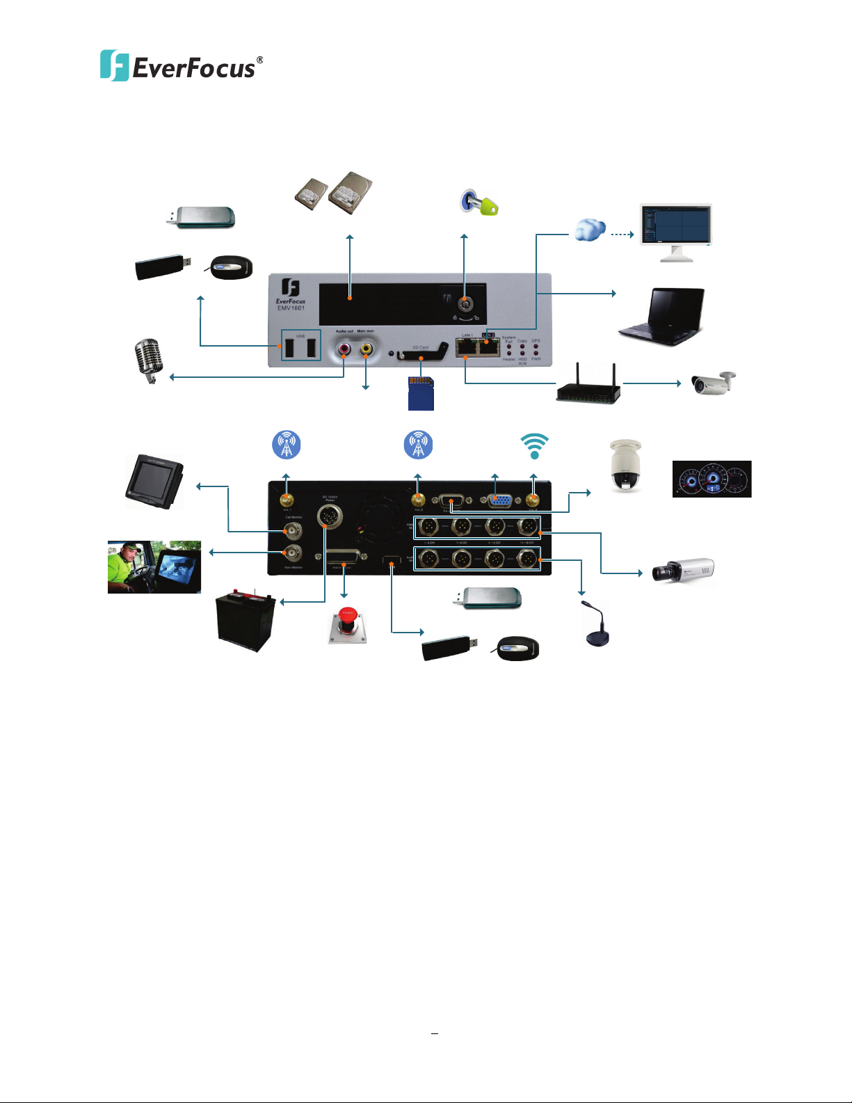
Mouse
Speaker
Main Monitor
(RCA)
HDD Key Lock
Power Supply
*Audio Input
Panic
Button
2.5" or 3.5" HDD x 1
3G USB Dongle
USB Storage Device
RS-232 CAN bus
(optional)
Call Monitor
WAN
CMS (Client PC)
Notebook / PC
(PoE) Hub / Switch
IP Cameras
(Optional)
SD Card (TBD)
*Analog Camera
Analog PTZ
Camera
Main
Monitor
(VGA)
Mouse
3G USB Dongle
USB Storage Device
Main Monitor
(BNC)
3G /4G LTE GPS
Wi-Fi
System Diagram
* This diagram uses EMV1601 as an example. The EMV401 / EMV801 have 4 / 8 video inputs and 4
/ 8 audio inputs respectively.
Page 12

EMV401 / 801 / 1601 Hybrid Mobile DVR
3
1.1 Features
• 4 / 8 / 16-Ch hybrid mobile DVR with independent audio-in per channel
• Support 4 / 8 / 16 channels in combination of analog and IP cameras, (EMV1601 supports
maximum 8 channels of IP cameras)
• Recording Resolution:
- Analog: D1/WD1 resolution
- IP: Up to 1080p resolution (depend on IP Camera)
• H.264 video compression format for better transmission and efficient storage
• Supports HDD up to 4TB
• Multiple serial interfaces
• Two 1Gb Ethernet ports
• 3-Axis G-Sensor embedded
• Internal temperature control
- Built-in two heaters (heater on: below 0°C / heater off: above 7°C)
• Shock and vibration resistant audio, video, alarm and power socket connectors
• Linux-based system
• Archives recordings to the USB storage device
• Supports multi-languages
Supports EverFocus’ CMS and Mobile Applications (MobileFocus)
•
• IR Remote Control
• Certificates: CE, FCC, EN50155, E-Mark
• Supports 3G USB dongle (Optional) *
• 3G, 4G LTE function / GPS function / Wi-Fi function (Optional) **
* 3G USB dongles tested by EverFocus include Huawei E161 / E173 / E180 / E220.
** Requires an external 3G / 4G / GPS / Wi-Fi antenna, please refer to 1.3 Optional Accessories.
For using 3G function, you can either use a 3G dongle or our 3G Receiver.
Page 13

EMV401 / 801 / 1601 Hybrid Mobile DVR
4
Note:
1.2 Packing List
• EMV401 / 801 / 1601 Hybrid Digital Video Recorder x 1
• HDD Tray (with 2 keys and 8 screws for 3.5” HDD, 6 screws for 2.5” HDD) x 1
• Z-Type Bracket x 2
• Long Screw (with 4 washers) x 4
• Short Screw (with 4 washers) x 4
• IR Remote Control (with two AAA batteries) x 1
• Power Harness Cable x 1
• Video Cable x 4 (EMV1601); x2 (EMV801); x1 (EMV401)
• Audio Cable x 4 (EMV1601); x2 (EMV801); x1 (EMV401)
• Alarm Cable x 1
• RS232/485 Cable x 1
• CD x 1 (Please see Note 3.)
• Quick Installation Guide x 1
1. Equipment configurations and supplied accessories vary by country. Please consult your
local EverFocus office or agents for more information. Please also keep the shipping
carton for possible future use.
2. Contact the shipper if any items appear to have been damaged in the shipping process.
3. The CD contains the IP Utility software, User Manual and Quick Installation Guide.
4. Risk of explosion if battery is replaced by an incorrect type. Dispose of used batteries
according to the instructions.
a. Use only two AAA dry cell batteries.
b. Do not dispose of the batteries in a fire as it may explode.
1.3 Optional Accessories
• 3G Receiver: For using 3G network function.
• 4G Receiver: For using 4G LTE network function.
• GPS Receiver: For using GPS function.
• Wi-Fi Antenna: For using Wi-Fi function.
Page 14
EMV401 / 801 / 1601 Hybrid Mobile DVR
5
1
2
3
4
6
7
8
9
5
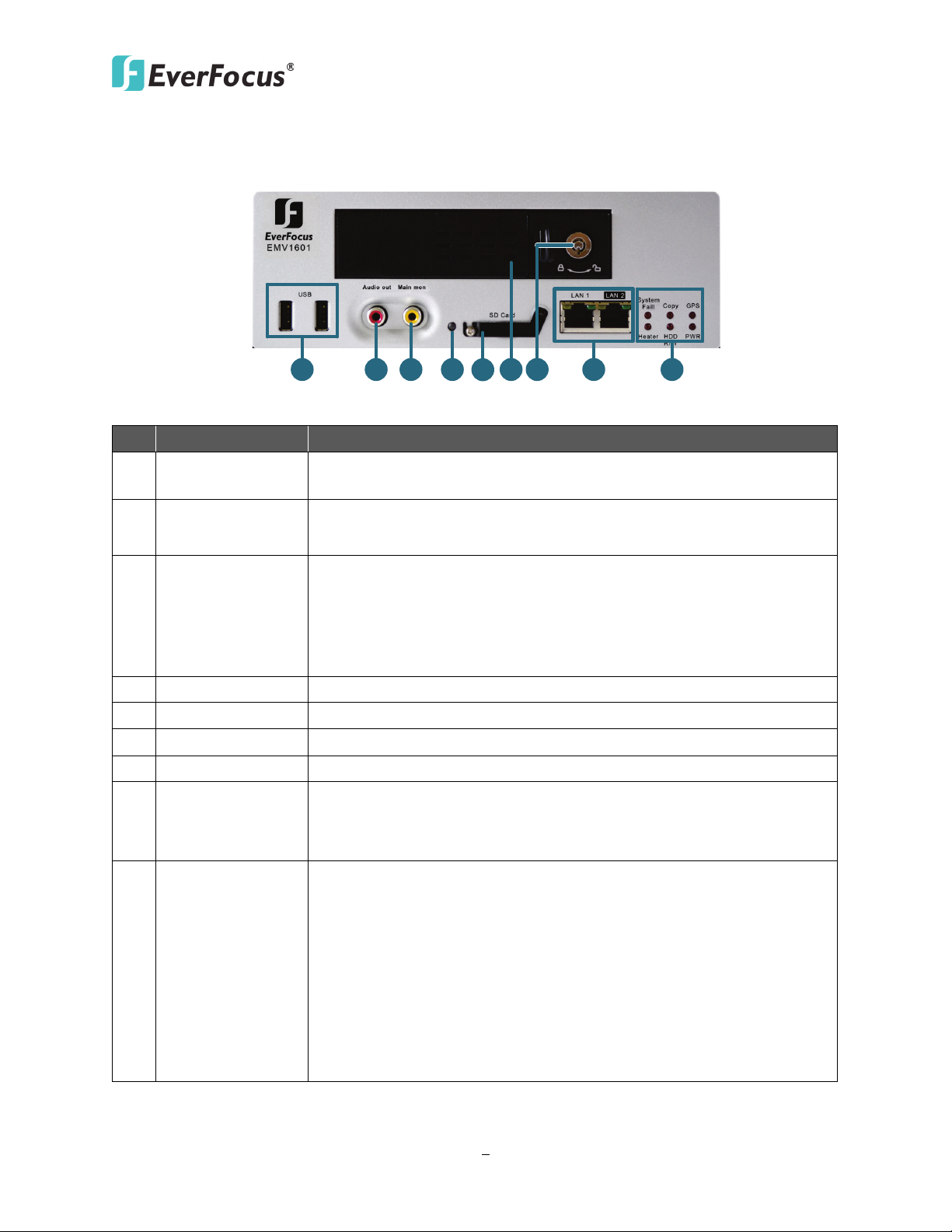
Two USB2.0 ports for connecting to the 3G USB dongle, USB
1.4 Front Panel
No. Name Description
1 USB2.0 Port
2 Audio Out
storage device or mouse.
RCA audio output for connecting to the speakers. The audio output
only works during playback.
RCA video output for connecting to a monitor for live view,
playback and displaying OSD.
3 Main Monitor
Note this mobile DVR has two Main Monitor outputs (one on the
front panel and the other on the rear panel). All of the Main
Monitor ports can be connected simultaneously.
4 IR Receiver Receives data from the infrared remote control.
5 SD Card (TBD) Insert a SD card for data storage. It is currently reserved.
6 HDD Drive Tray Installs a 3.5” or 2.5” HDD for recording.
7 HDD Key Lock Locks and unlocks the HDD tray.
Two RJ-45 ports for connecting to the network.
8 Ethernet Port
It’s recommended to use LAN 1 for connecting to the IP cameras
via a hub or switch, and use LAN 2 for WAN connection.
• GPS LED: Turns on when the mobile DVR is receiving the GPS
data.
• Power LED: Turns on when the power is supplied.
• Copy LED: Turns on when the mobile DVR is archiving data to
8 System LEDs
the USB storage device.
• HDD R/W LED: Turns on when the HDD is reading or writing.
• System Fail LED: Turns on when these events occur: HDD Full /
Fan Fail / HD Temperature.
• Heater LED: Turns on when the mobile DVR is overheating.
Page 15
EMV401 / 801 / 1601 Hybrid Mobile DVR
6
7
10
9 11 12
8
1 2
3
4 5
6
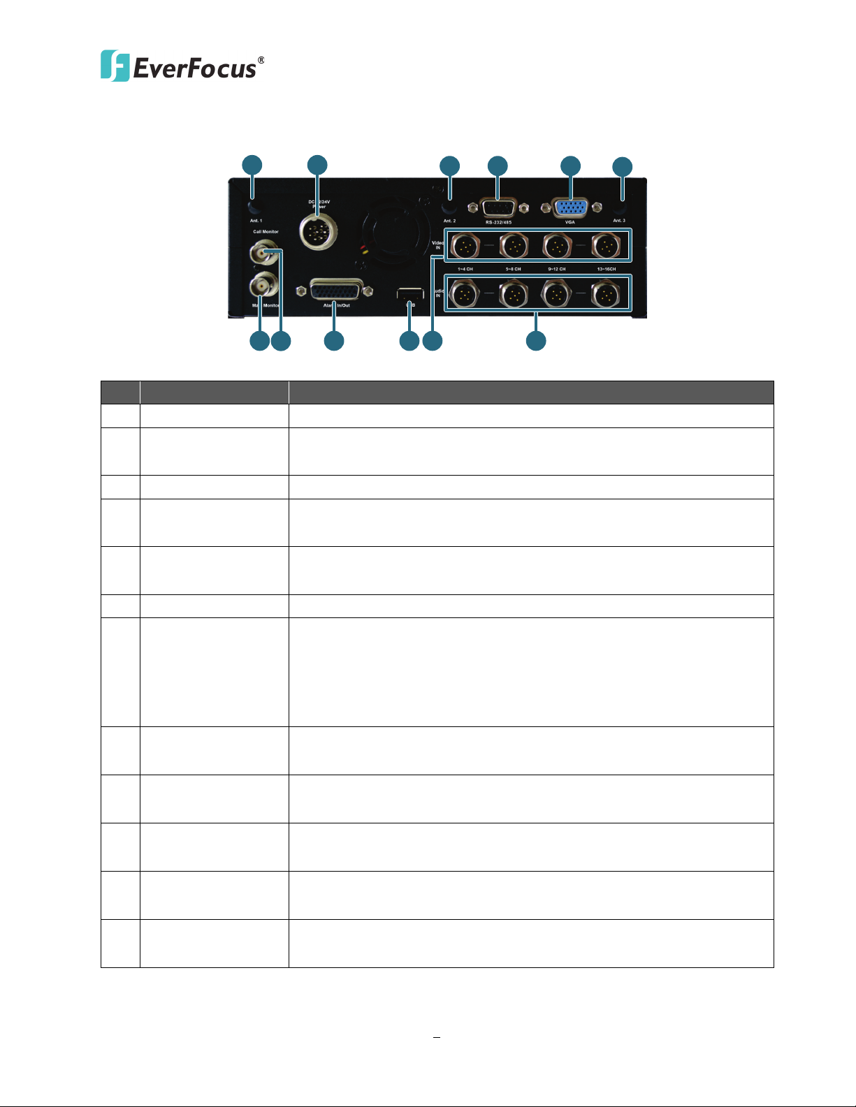
1.5 Rear Panel
No. Name Description
1 Antenna 1 (3G/4G) Connects to the 3G or 4G Receiver for using 3G / 4G LTE function.
2 DC Power Input
Power harness cable for connecting to 12 VDC ~ 24 VDC power
source. For details, please refer to 2.4.1 Power Harness Cable.
3 Antenna 2 (GPS) Connects to the GPS Receiver for using GPS function.
4 RS-232/485
Main Monitor
5
(VGA)
Connects to RS-232 (CAN bus) or RS-485 device (such as analog PTZ
cameras), please refer to 2.4.5 RS-232 /RS-485 Cable.
VGA video output for connecting to the main monitor for live view,
playback and displaying OSD.
6 Antenna 3 (Wi-Fi) Connects to the Wi-Fi antenna for using Wi-Fi function.
BNC video output for connecting to the main monitor for live view,
Main Monitor
7
(BNC)
playback and displaying OSD.
Note this mobile DVR has 3 Main Monitor outputs (one on the front
panel and the other 2 on the rear panel). All of the Main Monitor
ports can be connected simultaneously.
Call Monitor
8
(BNC)
9 Alarm In / Out
10 USB2.0 Port
BNC video output for connecting to the call monitor for displaying
the live view.
D-Sub connector for connecting to the supplied Alarm Cable. For
details, please refer to 2.4.4 Alarm Cable.
USB2.0 ports for connecting to the 3G USB dongle, USB storage
device or mouse.
11 Video Input
12 Audio Input
M12 connector for connecting to the supplied Video Cable. For
details, please refer to 2.4.2 Video Cable.
M12 connector for connecting to the supplied Audio Cable. For
details, please refer to 2.4.3 Audio Cable.
Page 16

EMV401 / 801 / 1601 Hybrid Mobile DVR
7
Bottom of glove box- horizontal mount
Bottom of passenger seat next to the driver
Underneath bulkhead-horizontal mount
Beside deriver seat-horizontal mount
Note: Do not install the hybrid mobile DVR on the floor or on the transmission access hatch.
2
Chapter
2. Getting Started
2.1 Installation
Before installation, choose a location in the vehicle where it can:
• Provide convenient access for installing or removing the hard disk
• Allow air to flow around the fan vents. Inadequate or improper air flow can impede proper
operation of the hybrid mobile DVR
Please avoid installing the hybrid mobile DVR to the following locations in the vehicle:
• That is subject to high vibration / sunlight levels
• That is subject to be drenched of the rain
• Where passengers can interfere with the hybrid mobile DVR
• Next to a heater duct
The following table lists the recommended location options in the vehicle:
Location
Front of bulkhead-horizontal mount Yes Yes Yes Yes
Convenient
Operation
Yes Yes Yes Yes
No Yes Yes Yes
Yes Yes No Yes
Yes Yes Yes Yes
Easy to
Install
Low
Vibration
Good
Air Flow
These locations have the highest levels of vibration and may be subject to water damage.
Page 17
EMV401 / 801 / 1601 Hybrid Mobile DVR
8
Support-Mount
Suspend-Mount
L-Type Bracket
Fixing Bracket
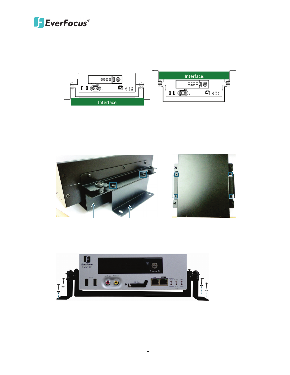
2.1.1 Mounting
The EMV401 / 801 /1601 can be mounted horizontally. Two mounting types are available:
Support-Mount and Suspend-Mount.
To install the L-type brackets to the hybrid mobile DVR for mounting:
1. Attach the supplied two L-Type Brackets to the Fixing Bracket on the hybrid mobile DVR.
Use the supplied four short screws with washers to screw the L-Type Brackets to the
Fixing Bracket.
2. Screw the hybrid mobile DVR to the interface using the supplied four Long Screws with
washers.
Page 18
EMV401 / 801 / 1601 Hybrid Mobile DVR
9
Note:
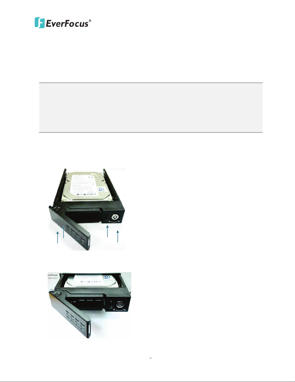
2.2 Hard Disk Installation
The EMV401 / 801 / 1601 supply with a 3.5” HDD tray for inserting a Hard Disk for video
recordings. Please follow the steps below to install the Hard Disk.
1. If you want to use a 2.5” HDD, make sure to use the supplied 2.5” HDD tray screws to
secure the HDD to the HDD tray.
2. The EMV401 / 801 / 1601 does not support hot swap for the hard disk. Ensure to power
off the hybrid mobile DVR before removing the hard disk. Also ensure to remove the
hard disk only after the power was completely shut off. This would protect and extend
the operating life of the hard disk.
1. Make sure the hybrid mobile DVR is power-off.
2. Place the hard disk in the HDD tray, secure the HDD with the supplied HDD Screws (8 for 3.5”
HDD and 6 for 2.5” HDD) on the bottom of the HDD tray.
3. Insert the HDD tray to the hybrid mobile DVR.
Page 19
EMV401 / 801 / 1601 Hybrid Mobile DVR
10
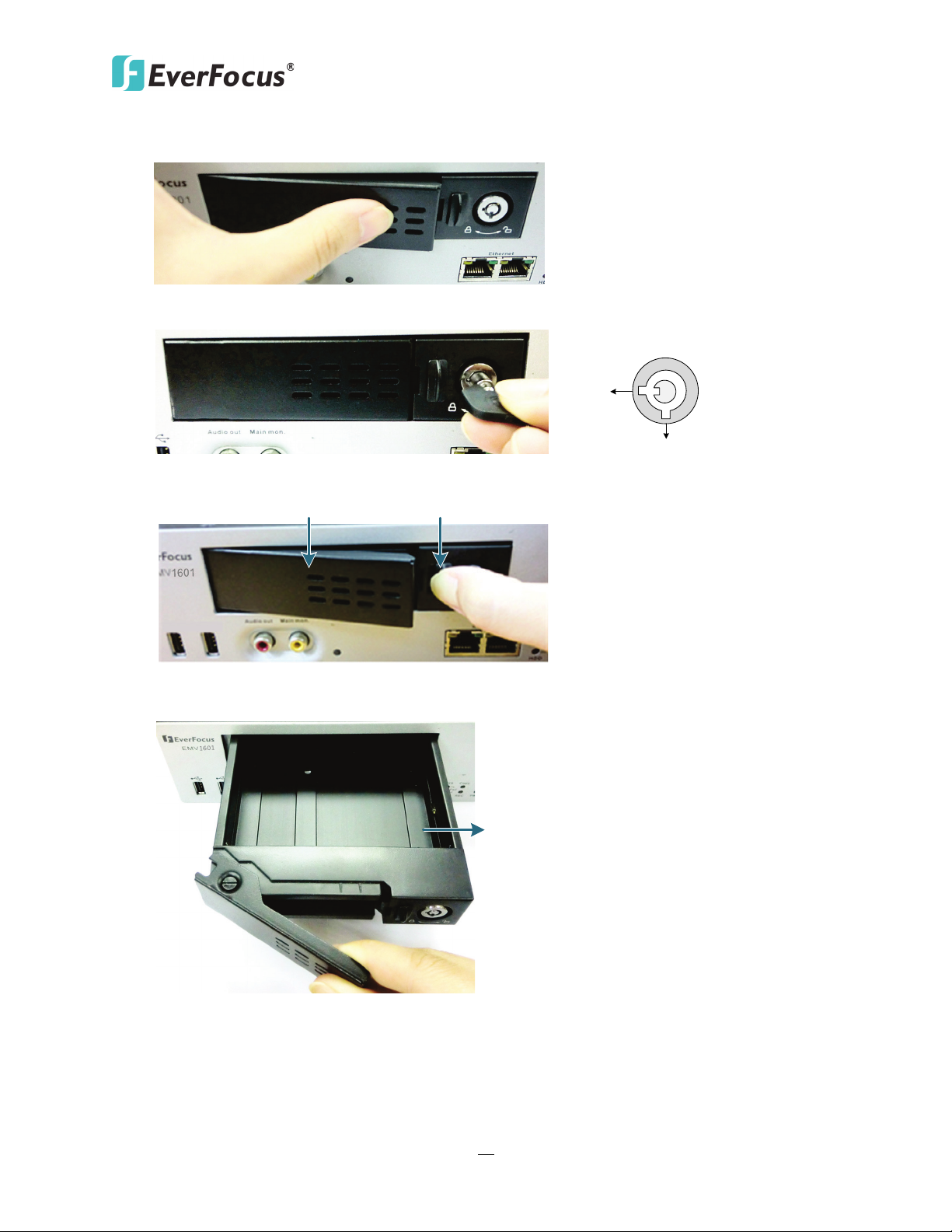
Locked
Unlocked
Lock ClipLatch
Hard Disk Tray
4. Push the Latch to fasten it to the HDD tray.
5. Lock the HDD tray using the supplied key.
6. To remove the HDD tray, slightly push the Lock Clip to loosen the Latch of the HDD tray.
7. Pull out the HDD tray.
Page 20
EMV401 / 801 / 1601 Hybrid Mobile DVR
11
24V+ (Red)
IGN (Yellow)
Relay (24V)
EMV1601 (Rear Panel)
GND (Black)
Vehicle Battery
+
-
24V
Power Harness Cable
Fuse (15A)
Lock
ACC
On
Power
ACC
Note:
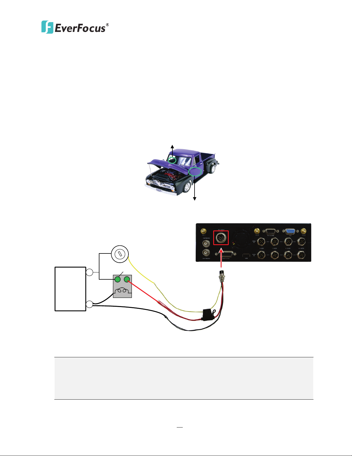
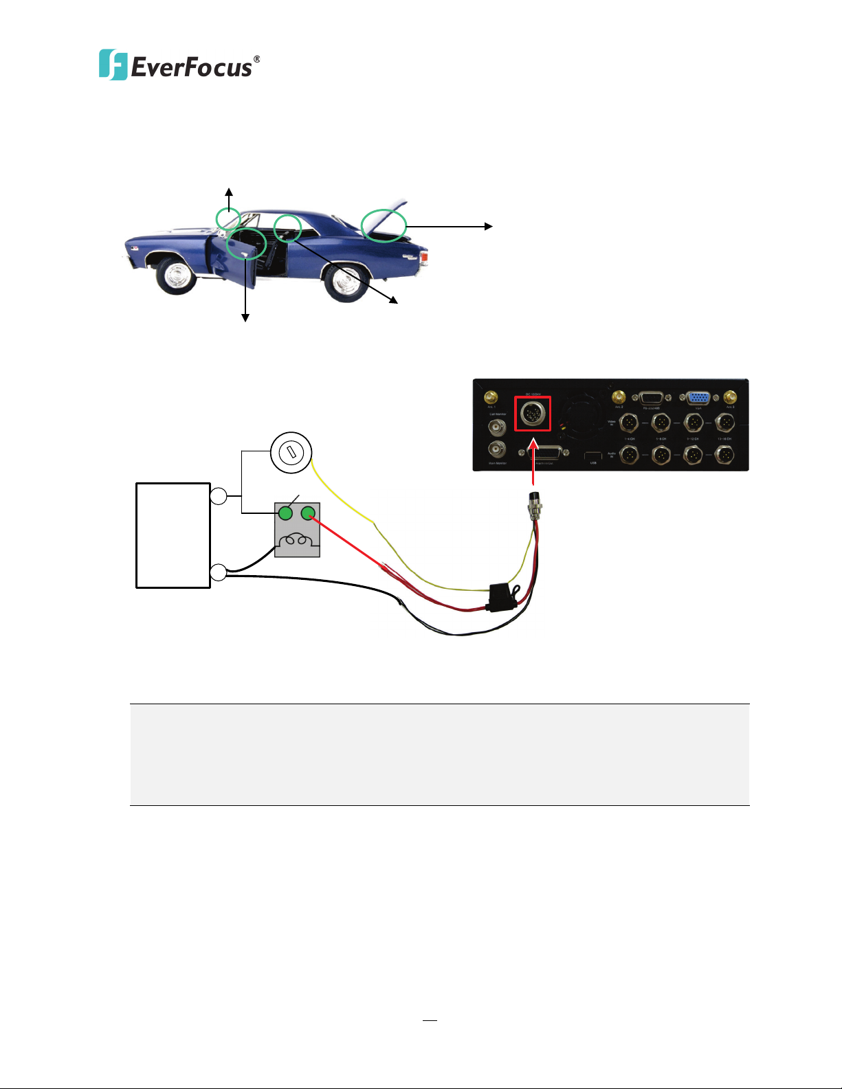
2.3 Vehicle Connection
The EMV401 / 801 / 1601 supports input power voltage between 10 VDC ~ 32 VDC. You can
install the hybrid mobile DVR in all kinds of vehicles support the above power voltage. The
diagrams below are examples to illustrate the connection inside car / truck with 12 VDC / 24 VDC.
* The following figures are using EMV1601 for example; the differences among the three models
are the video / audio / alarm inputs numbers.
2.3.1 Connecting to a Truck with 24 VDC
Glove box (inside or underneath)
Driver’s seat (between the seat and the back panel) or underneath the Passenger seat
1. If the car is without an ignition key, please connect the IGN (yellow) wire directly or
via a switch to the vehicle battery.
2. It is suggested to use a relay in the installation. Otherwise, the mobile DVR will always
draw the power from the vehicle battery.
Page 21
EMV401 / 801 / 1601 Hybrid Mobile DVR
12
12V+ (Red)
IGN (Yellow)
Relay (12V)
EMV1601 (Rear Panel)
GND (Black)
Vehicle Battery
+
-
12V
Power Harness Cable
Fuse (15A)
Lock
ACC
On
Power
ACC
Note:
Trunk
Passenger seat (underneath)
Glove box (inside or underneath)
Driver seat (between the seat and side panel)
2.3.2 Connecting to a Car with 12 VDC
1. If the car is without an ignition key, please connect the IGN (yellow) wire directly or
via a switch to the vehicle battery.
2. It is suggested to use a relay in the installation. Otherwise, the mobile DVR will always
draw the power from the vehicle battery.
Page 22
EMV401 / 801 / 1601 Hybrid Mobile DVR
13
Front View
Rear View
Mouse
Speaker
Main Monitor
Notebook / PC
Power Supply
Analog Camera
Audio Input
2.5"or
3.5" HDD
WAN
CMS (Client PC)
1
2
3
4
7 8
9
5
3G USB
Dongle
5 6
(PoE) Hub / SwitchIP Cameras
Audio Cable
Video Cable
Power Harness Cable
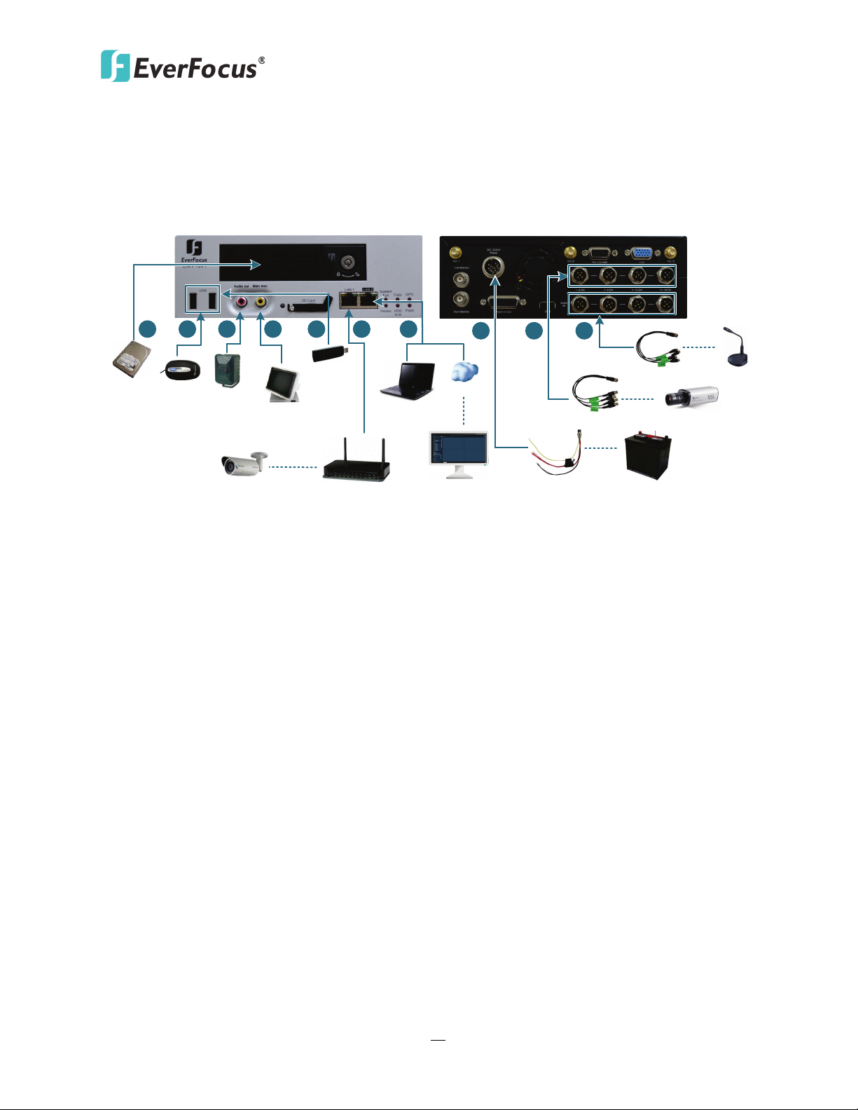
2.4 Basic Connection
After installing the EMV401 / 801 / 1601 in the vehicle, you can start connecting the hybrid
mobile DVR to the external devices. The instructions below describe the basic connection to the
EMV401 / 801 / 1601. For details on cable connections, please refer to the following sections.
1. To record videos, insert a 2.5” or 3.5” HDD to the HDD tray. Remember to lock the HDD Key
Lock after inserting the HDD or the recording will not start (see 2.2 Hard Disk Installation).
2. To control the system, connect a mouse to the hybrid mobile DVR or use the supplied IR
Remote Control.
3. To listen to audio of video source, connect a speaker to the Audio-out RCA socket. Note that
the speaker with a (built-in) amplifier and external power is required.
4. To view videos, connect a monitor to the RCA port using the RCA cable supplied by the
monitor manufacturer. You can also connect other video out ports, please refer to 2.5
Monitor Connection.
5. To manage the hybrid mobile DVR over network:
a. Use a standard RJ-45 cable to connect the hybrid mobile DVR to the network.
b. Connect a 3G USB dongle to the USB port on the hybrid mobile DVR. For details on 3G
wireless network settings, please refer to 6.6.3 Mobile.
6. You can optionally connect a (PoE) switch / hub to the LAN1 port of the hybrid mobile DVR
using a standard RJ-45 Ethernet cable for connecting the IP cameras.
7. Connect the supplied Power Harness Cable to the power supply in the vehicle for powering
the hybrid mobile DVR and the connected cameras. For details on vehicle connection, please
refer to 2.3 Vehicle Connection.
8. Connect the cameras to the hybrid mobile DVR using the supplied Video Cable.
9. Connect the audio input devices to the hybrid mobile DVR using the supplied Audio Cable.
Page 23
EMV401 / 801 / 1601 Hybrid Mobile DVR
14
IGN (Yellow)
DC Power In (Red)
GND (Black)
10 VDC ~ 32 VDC
Pins on Power Cable
Power Input
EMV1601 (Rear Panel)
Power Harness Cable
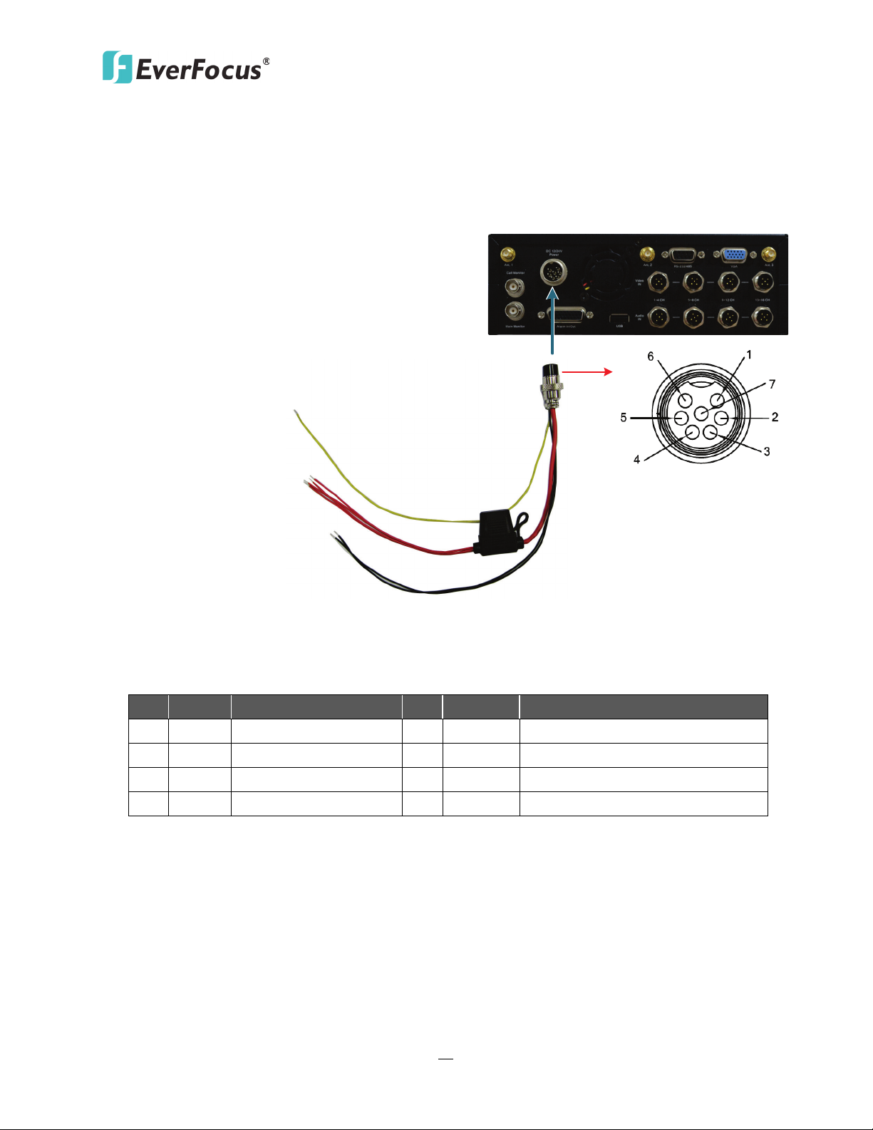
2.4.1 Power Harness Cable
You can connect the mobile DVR to a power source between 10 VDC ~ 32 VDC.
Pin Assignment
No. Color Description No. Color Description
1 Red DC Power Input 5 Black GND
2 Red DC Power Input 6 Black GND
3 Red DC Power Input 7 Yellow IGN
4 Red DC Power Input
Page 24
EMV401 / 801 / 1601 Hybrid Mobile DVR
15
EMV1601 (Rear Panel)
Video Input
Camera 1
Camera 16
Video Cable x 4
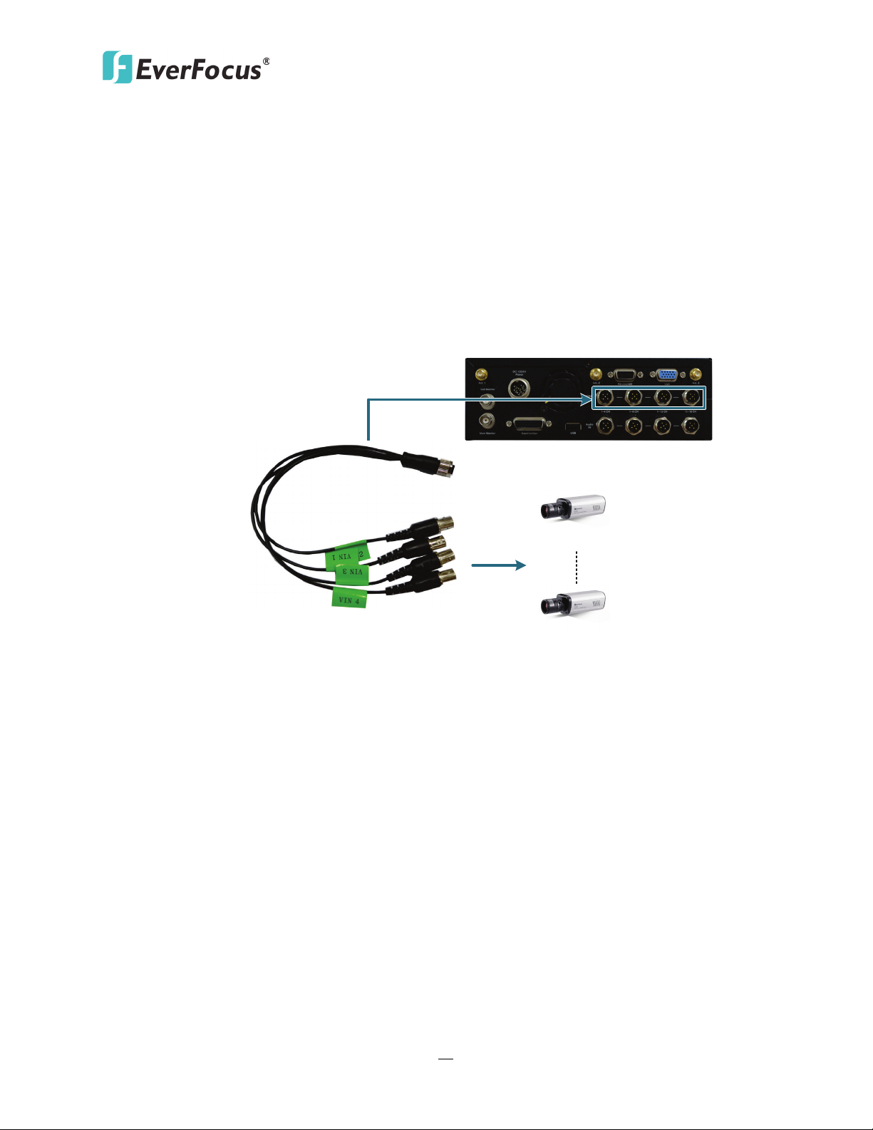
2.4.2 Video Cable
The EMV401 / 801 / 1601 have 1 / 2 / 4 Video In ports for connecting 4 / 8 / 16 analog
cameras using the supplied Video Cables.
The Video Cables are all labeled with VIN 1~ VIN 4, and you can connect any Video Cable to
any of the Video In ports on the mobile DVR. If the Video Cable connects to 5-8 CH Video In
port, the cable labeled as VIN 1 will be channel 5 and so forth.
(The following figure uses EMV1601 as an example).
Page 25
EMV401 / 801 / 1601 Hybrid Mobile DVR
16
EMV1601 (Rear Panel)
Audio Input
Audio Input 1 Audio Input 16
Audio Cable
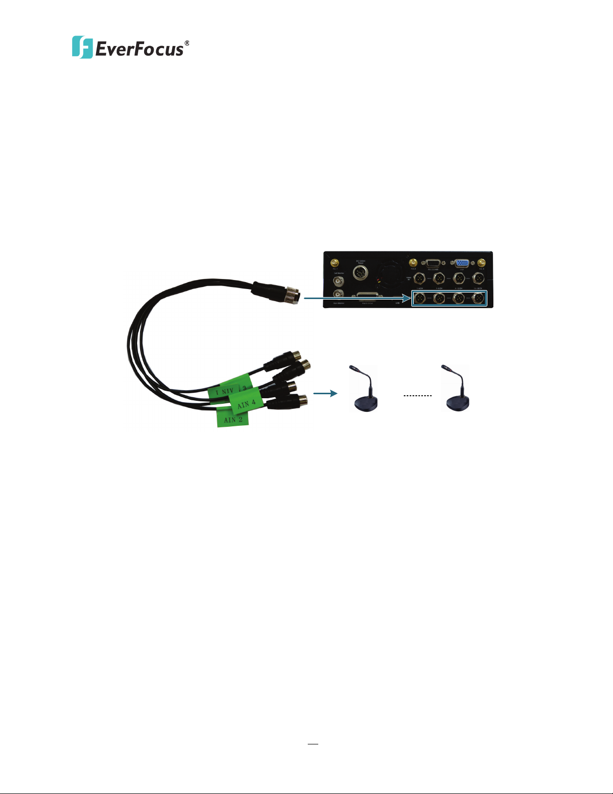
2.4.3 Audio Cable
The EMV401 / 801 / 1601 have 1 / 2 / 4 Audio In ports for connecting 4 / 8 / 16 microphones
using the supplied Audio Cables.
The Audio Cables are all labeled with AIN 1~ AIN 4, and you can connect any Audio Cable to
any of the Audio In ports on the mobile DVR. If the Audio Cable connects to 5-8 CH Audio In
port, the cable labeled as AIN 1 will be channel 5 and so forth.
(The following figure uses EMV1601 as an example).
Page 26
EMV401 / 801 / 1601 Hybrid Mobile DVR
17
EMV1601 (Rear Panel)
Alarm In / Out
Alarm Cable
Alarm Output
Alarm Input
Pins on Alarm Cable
1
10
19
9
18
26
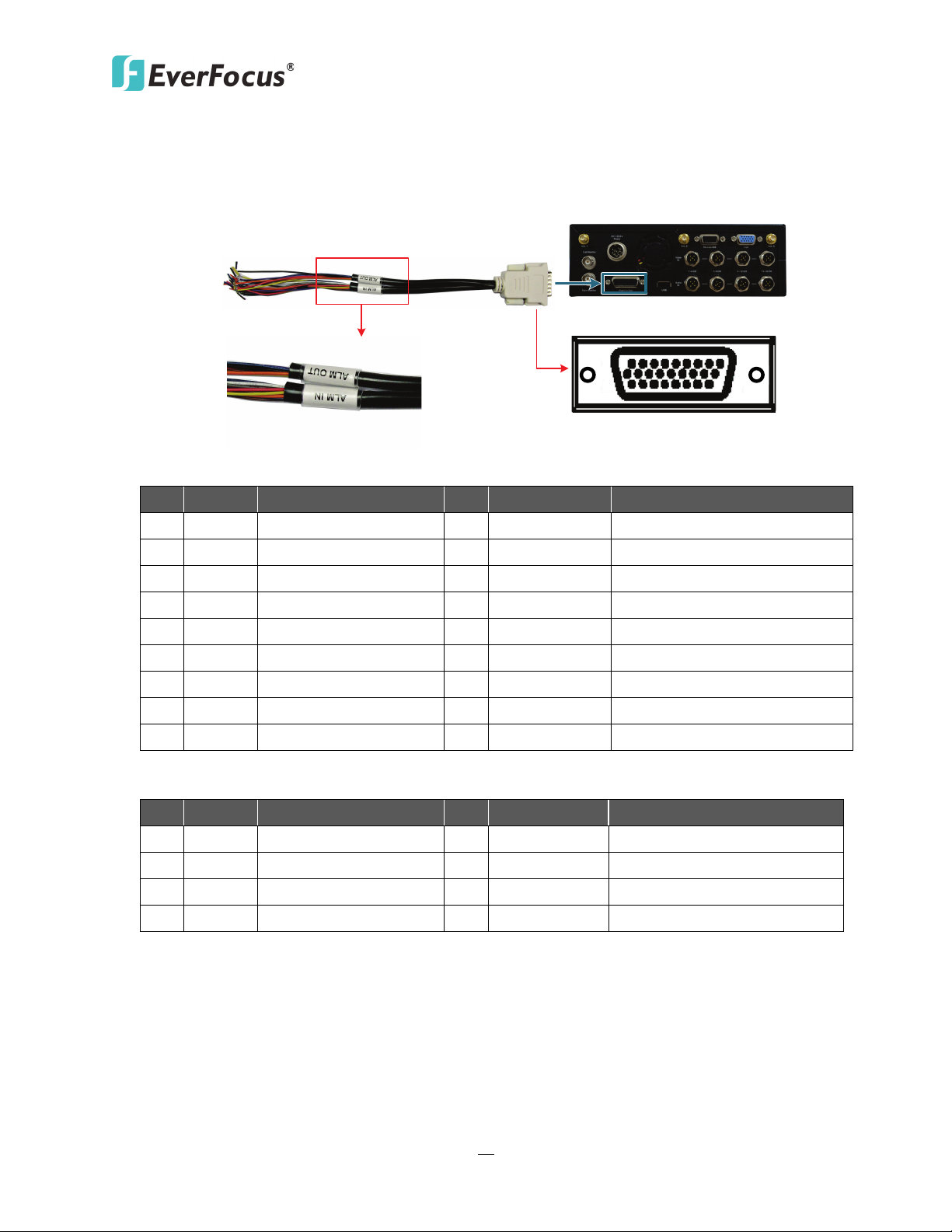
2.4.4 Alarm Cable
You can connect the hybrid mobile DVR to 16 / 8 / 4 alarm inputs and 2 alarm outputs.
Alarm Input
No. Color Description No. Color Description
1 Blue ALM_IN1 10 Black GND
2 Purple ALM_IN2 11 Purple ALM_IN9
3 Orange ALM_IN3 12 Green ALM_IN10
4 Gray ALM_IN4 13 Red ALM_IN11
5 Brown ALM_IN5 14 Brown ALM_IN12
6 Red ALM_IN6 15 Blue ALM_IN13
7 Yellow ALM_IN7 16 Yellow ALM_IN14
8 White ALM_IN8 17 Black ALM_IN15
9 Black GND 18 Orange ALM_IN16
Alarm Output
No. Color Description No. Color Description
19 Black GND 23 Red ALM1-NC
20 Black GND 24 Blue ALM2-NO
21 Orange ALM1-COM 25 Brown ALM2-NC
22 Yellow ALM2-COM 26 Purple ALM1-NO
Page 27
EMV401 / 801 / 1601 Hybrid Mobile DVR
18
EMV1601 (Rear Panel)
Audio Input
RS-232 / 485 Cable
Analog PTZ Camera
RS-232
CAN Bus
1 - - 6 -
4 - 9 Black
GND
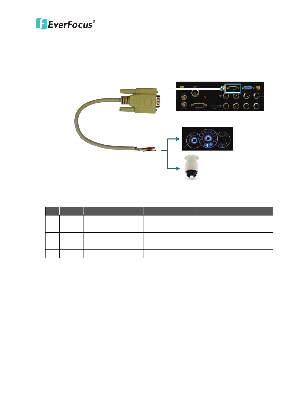
2.4.5 RS-232 / RS485 Cable
You can connect the I/O devices such as a CAN Bus / analog PTZ cameras using the RS-232 / RS485 Cable.
RS-232 / RS-485
No. Color Description No. Color Description
2 Blue RS-232_RX 7 Purple RS-485B (-)
3 Yellow RS-232_TX 8 Gray RS-485A (+)
5 Red GND
Page 28
EMV401 / 801 / 1601 Hybrid Mobile DVR
19
Main Monitor
Call Monitor
BNC Cable
VGA Cable
BNC Cable
RCA Cable
Main Monitor
Main Monitor
Front Panel
Rear Panel
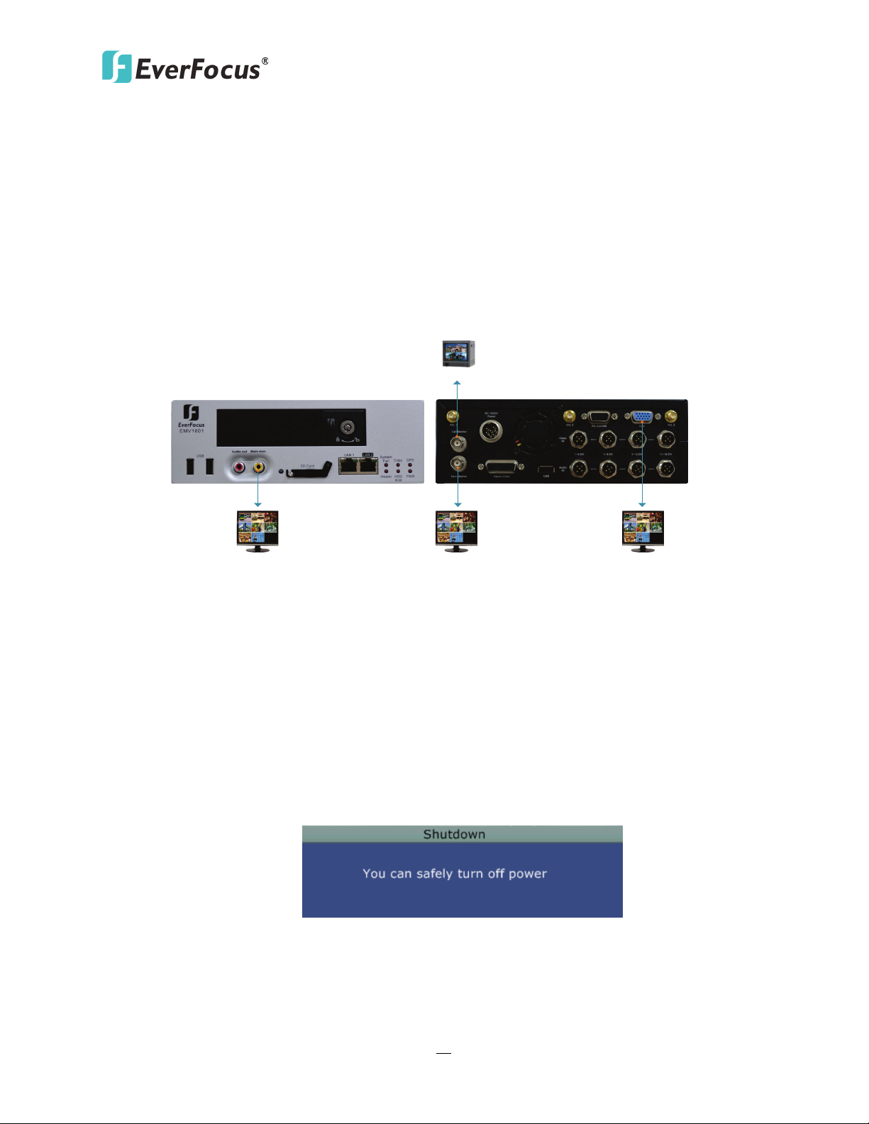
2.5 Monitor Connection
The EMV401 / 801 / 1601 have 3 Main Monitor ports and 1 Call Monitor port. You can connect
the monitors to the BNC, VGA or RCA Main Monitor and BNC Call Monitor ports of the hybrid
mobile DVR. All of the Main and Call Monitor ports can be used simultaneously.
The configuration can only be operated on the Main Monitors, and the 3 Main Monitor outputs
have the identical functionality.
Make sure that the connected monitor's specifications comply with these resolution requirements.
(This figure uses EMV1601
hybrid mobile DVR as an example).
2.6 Turning On / Off the Power
Before powering on the hybrid mobile DVR, please make sure the internal HDD have been
installed properly. Once you have completed the basic cable connections, you are ready to turn
on the hybrid mobile DVR. Simply plug in the power source. The POWER LED will light up if
power is normal. Once the system has finished loading, you can begin to set up the menu
options for the hybrid mobile DVR.
To turn off the power, please go to OSD Root Menu > System Setting > Miscellaneous setting page,
click Shutdown (refer to 6.8.7 Miscellaneous). After the message pops up as below, you can now
and
turn off the power source.
Note that when the hybrid mobile DVR is placed in an environment where the temperature is
very low (for example, -40°C, the hybrid mobile DVR will NOT turn on immediately.)
Page 29
EMV401 / 801 / 1601 Hybrid Mobile DVR
20
2.7 Checking the Dynamic IP Address
You can look up the IP address and access the Web interface of the hybrid mobile DVR using the
IP Utility (IPU) program, which can be downloaded from EverFocus’ Website:
http://www.everfocus.com/HQ/Support/DownloadCenter_p1.aspx. Please connect the hybrid
mobile DVR in the same LAN of your computer.
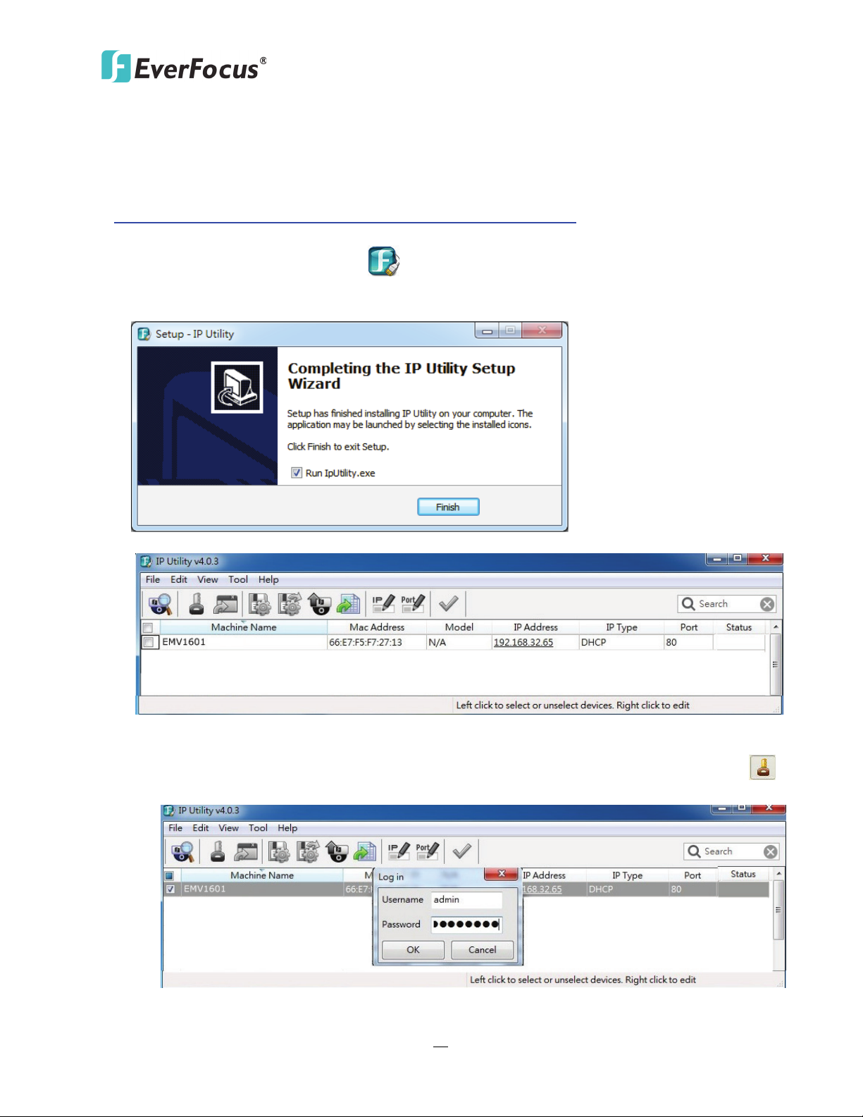
1. Save IP Utility Setup AutoRun.exe in your computer. Double click the .exe file and follow
the on-screen instructions. Check Run IPUtility.exe and click the Finish button, the IP Utility
will be launched to search the IP devices connected in the same LAN automatically.
2. To optionally configure the Machine Name, IP Address, IP Type or Port Number using the IPU:
a. Log in the hybrid mobile DVR by checking the desired model and then click the Log in
icon. The Log in dialog box appears.
Page 30
EMV401 / 801 / 1601 Hybrid Mobile DVR
21
Note:
Note: Most networks uses DHCP to assign IP address, if you are unsure of your network
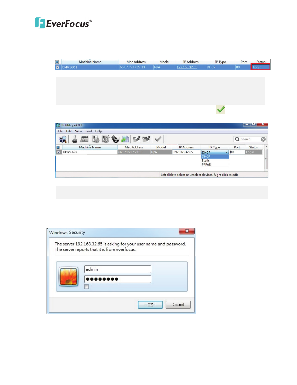
b. Type the Username and Password. Click the OK button, the status of the selected camera
will display Login.
1. The default user ID is admin and the default password is 11111111.
2. If you select more than one hybrid mobile DVRs that have the same user ID /
password, you will be able to log in several hybrid mobile DVRs at once.
c. Right click the column to configure the setting. Click Apply Changes button to apply
and save the settings.
settings, please consult your network administrators for configuration details.
3. To access to the Live View window, double click the IP address of the desired device, the login
window pops up. Type the user ID and password to log in. By default, the user ID is admin and
the password is 11111111.
Page 31

EMV401 / 801 / 1601 Hybrid Mobile DVR
22
4. When first connecting to the hybrid mobile DVR’s IP address, the following dialog will appear.
Please check the box and click the Run button to run the EverFocus Viewer application.
5. You might be required to download ActiveX and JAVA software for viewing the camera feed.
If asked, click Yes. For more details, please refer to 7.3.1 Installing ActiveX Controls.
6. You may need to turn User Account Control off if you still can’t see the Remote Live View.
7. On the computer, click Start > Control Panel > System and Security > Action Center (click
Change User Account Control Settings), the User Account Control Settings window appears.
Adjust the slide bar to Never Notify and then click OK. Restart your computer if requested.
8. If your PC or laptop is running with Windows, it’s required to run the browser as administrator
when first entering the remote web page of the device. Go to C:\Program Files (x86)\Internet
Explorer, right-click the browser and then click Run as administrator.
9. Now you will be able to see the remote live page.
Page 32

EMV401 / 801 / 1601 Hybrid Mobile DVR
23
Straight-through
Right: Pinout of a straight-through cable.
2.8 Connecting the Hybrid Mobile DVR to the Network
There are three methods to connect the hybrid mobile DVR to the network: Router or LAN
Connection, Direct High‐Speed Connection and One‐to‐One Connection. For more information of
the network, please refer to Appendix A. Network Overview.
2.8.1 Router or LAN Connection
This is the most common connection in which the IP camera is connected to a router and
allows multiple users on and off site to see the IP camera on a LAN/WAN (Internet). The
camera must be assigned an IP address that is compatible with its LAN. By setting up port
forwarding on the router, you can remotely access the cameras from outside of the LAN via
the Internet. To remotely access the Web interface, please refer to 7. Remote Access to the
hybrid Mobile DVR. To set up port forwarding, please consult the manual of the router or
refer to Appendix B: Linksys & D-Link Port Forwarding.
LAN patch cable
Page 33

EMV401 / 801 / 1601 Hybrid Mobile DVR
24
Connection Procedure:
The First step is to purchase or make a straight through cable. We recommend
purchasing one if you have never made a straight through cable. Please remember you
can not use a cross-over network cable for this application.
Once you have a straight through cable plug one end into the LAN port on the back of
the recorder and the other into the router.
Log into the EverFocus hybrid mobile DVR menu and go to the Network Setting Menu.
To let the router automatically assign an address:
Set the Network Type to DHCP. Make sure to write down the IP address and the
Gateway.
Exit from the Menu to save settings.
To manually assign an address:
Go to a computer connected on the same network as the mobile DVR.
Click on the Start button and choose Run.
If using Windows Vista, choose Search instead.
Type “command” and click on OK.
In Vista, you will need to double-click on the “Command Prompt” file to open it.
In the DOS prompt, type “ipconfig” and press Enter.
The network information will be displayed on a screen similar to the one below.
In Windows Vista, look for the information that says “IP v4”.
Page 34

EMV401 / 801 / 1601 Hybrid Mobile DVR
25
Note: The hybrid mobile DVR’s IP address will only work at the location of the
Note: If you changed to a different port other than 80, you will need to include this
http:// (the IP address given by your internet service provider):portnumber
Take the values for Subnet Mask and Default Gateway and input them into the
hybrid mobile DVR; these values should be exactly the same in both devices.
However, you should change the last number of the IP address. For example, if the
IP address of the computer is 192.168.2.101, the hybrid mobile DVR’s IP address
should be 192.168.002.050.
To access the hybrid mobile DVR from a computer simply open Internet Explorer and in
the address bar type:
http:// (IP address of the hybrid mobile DVR)
mobile DVR. To connect from a different location over the Internet, see below.
To set the hybrid mobile DVR for Internet Connection through router:
The next step is to open ports within your router. Log into the router using a PC and
open the following ports.
Ports to open: 80
If your Internet service provider blocks port 80, you can change it to a different port
in the hybrid mobile DVR’s Network Menu Setup; open/forward that port instead.
If you are using a Linksys or D-Link router, see Chapter 8 for basic support on
setting up ports. For any other router, you will need to contact the manufacturer
for support.
To access the hybrid mobile DVR from a computer simply open Internet Explorer and in
the address bar type:
http:// (the IP address given by your internet service provider)
at the end of the IP address:
If you have a WAN Dynamic IP address and have opened the ports, go to Chapter 7 to
setup DDNS.
Page 35

EMV401 / 801 / 1601 Hybrid Mobile DVR
26
Note: If you have a dynamic IP address, you can set the mobile DVR to DHCP to
Note: When using this type of connection, only one device can be connected to the
2.8.2 Direct High-Speed Connection
In a Direct High-Speed Connection, the camera connects directly to a modem without the
need for a router. You need to set the static or dynamic WAN IP address assigned by your ISP
(Internet Service Provider) in the camera’s configuration web pages. To access the camera,
just type “http://xxx.xxx.xxx.xxx”, where xxx.xxx.xxx.xxx is the IP address given by your ISP. If
you have a dynamic IP address, this connection may require that you use DDNS for a reliable
connection.
Connection Procedure:
The first step is to purchase or make a straight through cable. We recommend
purchasing one if you have never made a straight through cable. Please remember you
can not use a cross-over network cable for this application
Once you have a straight through cable plug one end into the LAN port on the back of
the recorder and the other into the high speed modem.
Log into the EverFocus hybrid mobile DVR menu and go to the Network Setting Menu.
Input the Static IP address, the Subnet Mask, and the Gateway that you obtained from
the internet service provider.
automatically detect the network settings. Therefore, it can use a dynamic IP address.
Exit from the hybrid mobile DVR’s Menu to save the settings.
To access the hybrid mobile DVR from a computer, open Internet Explorer and in the
address bar type: http:// (IP address given by your internet service provider)
modem at a time. You will need to use a computer at a different location to test the
connection s.
Page 36

EMV401 / 801 / 1601 Hybrid Mobile DVR
27
Right: Pinout of a crossed-over cable.
2.8.3 One-to-One Connection
You can connect directly without using a switch, router or modem. However, only the PC
connected to the camera will be able to view the IP camera. You will also have to manually
assign a compatible IP address to both the computer and the IP camera. Unless the PC has
another network connection, the IP camera will be the only network device visible to the PC.
See the diagram below:
Connection Procedure:
The First step is to purchase or make a cross-over cable. We recommend purchasing one
if you have never made a cross-over cable. Please remember you can not use a straight
through network cable for this application.
Once you have a cross-over cable plug one end into the LAN port on the back of the
hybrid mobile DVR and the other into the network card on the back of the computer.
Log into the EverFocus hybrid mobile DVR menu and go to the Network Setting Menu.
You must use the Static IP option for this type of connection.
Assign an IP of 192.168.001.003, a Subnet Mask of 255.255.255.000, and a Gateway of
192.168.001.001. You can ignore DNS Server.
The next step is to set the computer’s network settings to match those of the hybrid
mobile DVR. You will need Administrator privileges on your Windows machine to do this.
To assign a fixed IP address in Windows 2000/XP, follow the instructions below:
Page 37

EMV401 / 801 / 1601 Hybrid Mobile DVR
28
Go to Start. Double-click on Control Panel.
Click Network and Sharing Center.
Click Local Area Connection.
Page 38

EMV401 / 801 / 1601 Hybrid Mobile DVR
29
Click Properties.
Click on Internet Protocol Version 4 (TCP/IPv4) and then click Properties.
Page 39

EMV401 / 801 / 1601 Hybrid Mobile DVR
30
Select Use the following IP address. Assign an IP address of 192.168.1.2, a Subnet
Mask of 255.255.255.0, and a Default Gateway of 192.168.1.1 and then click OK.
Restart both of the computer and the hybrid mobile DVR.
To access the hybrid mobile DVR from the computer, simply open Internet Explorer
and in the address bar type: http://192.168.1.3
Page 40

EMV401 / 801 / 1601 Hybrid Mobile DVR
31
3
Chapter
3. General Operation
There are two ways to control the OSD menu of the EMV401 / 801 / 1601: with a Mouse or the
supplied handheld IR Remote Control. For details on the IR remote control, please refer to
Appendix E, IR Remote Control. This chapter will discuss the basic operations using the mouse.
3.1 USB Mouse Operation
3.1.1 How to Select a Channel / Enable Audio Out
1. In the Live View window, you can select a channel by clicking once on the desired
channel screen. The selected screen will be highlighted by a red frame.
2. Double clicking on a channel screen will display full screen for this channel.
3. To enable audio out, click the Audio Icon at lower-left side of the screen to switch the
Audio Output function to the desired channel or disable the Audio Output function.
3.1.2 OSD Root Menu
1. Right-click the mouse, the OSD Root Menu window appears.
2. Click on any icon to enter to the setup menus.
3. Click the button on the top-right corner or right-click to close the OSD Root Menu.
Page 41

EMV401 / 801 / 1601 Hybrid Mobile DVR
32
←
3.1.3 Field Input Options
You may found the following fields in the Configuration menu. Follow the instructions below
to configure the settings.
Text Box: Click on the box and an on-screen keyboard will appear.
On-Screen Keyboard: Click on a button to input that character. The buttons on the right and
bottom have the following functions:
Caps Switch to capital letters
Delete the letter backwards
Confirm the selection
Move to left
Move to right
Space Enter a space
Drop-Down Box: Click on the down arrow to see all selections, then directly click on an option
to select it.
Check Box: Click on the box to enable it (checked) or disable it (unchecked).
Button: Click the button to execute the function.
Bar: Slide the bar to the left or right for adjusting the set point.
Page 42

EMV401 / 801 / 1601 Hybrid Mobile DVR
33
.4 User
3.2 General Operation
3.2.1 Login
In order to access EMV401 / 801 / 1601, you may be prompted to log in for authority
identification. To log in, follow the steps below:
1. Right click on the screen to display the Root Menu. The following window appears.
2. Select the user name from the User name drop-down list and input the password. The
default user name and password are:
User Name: admin
Password: 11111111
Note: For details on setting up multiple user accounts, please refer to 6.8
Management.
To input the password, click the Password field to bring up the on-screen keyboard. Click
on each button to input the desired characters. When finished, click to confirm the
password.
3. Click the Login button to log in the system.
Page 43

EMV401 / 801 / 1601 Hybrid Mobile DVR
34
3.2.2 Forget Your Password
1. If you forget your password, please email the Serial Number of the hybrid mobile DVR to
techsupport@everfocus.com, and then EverFocus will send you a verification code.
2. Input this verification code in the Password field of the Login window within 24 hours,
and check the Verification Mode box.
3. Click Login to log in the hybrid mobile DVR.
Note: This verification code is effective within 24 hours only, so please set up a new
password in the System Setting page (refer to 6.8.4 User Management).
3.2.3 Camera Selection
You can control each camera individually by selecting that camera. To select a camera, follow
the instructions below.
Click a camera on the screen, and the selected camera will be highlighted with a red frame. All
cameras will be selected when you scrolling the mouse up / down between the first and the
last channel.
Page 44

EMV401 / 801 / 1601 Hybrid Mobile DVR
35
3.2.4 Audio Selection
In order to utilize the audio function, please follow the instructions below before switching on
the audio function.
Note: The Audio function is unavailable for Germany.
1. Connect the audio source and/or audio output amplifier to the hybrid mobile DVR.
2. Go to Camera setting menu (OSD Root Menu > System > Camera > Camera Status).
3. Click the Set button of the analog camera.
4. Check the box to enable the Record Audio option and select an audio input device. You can
select multiple cameras to one single audio input device.
Note that the hybrid mobile DVR only provide one channel audio output. You can switch the
Audio Output function to either one from the 16 cameras. To switch the Audio Output
function to the desired camera:
On the bottom of the live view screen, click the Audio icon to switch the Audio Output
function to the desired camera or disable the Audio Output function.
Page 45

EMV401 / 801 / 1601 Hybrid Mobile DVR
36
1
2
3
4
5
6
7
8
9
10
11
12
No
Click to display the Layout Bar as shown below. Select a layout type for
4
4. OSD Root Menu
Chapter
Name Description
1 Playback
2 PTZ
3 Layout
Click to display the Playback Bar for viewing the recording videos. For
details, please refer to 5. Search and Playback.
Click to display the PTZ Control Panel for controlling the connected PTZ
cameras. For details, please refer to 4.1 PTZ.
the live view display on the Main Monitor. For details, please refer to
4.2 Layout Switching.
Page 46

37
4
Click to display the Channel Changing Bar as show below. To switch the
Click to enter the auto sequential switching mode. Click again to
Click to display the Search menu for setting up the Search mode for
for Playback Back.
Click to display the Copy menu for archiving the recordings or log data
EMV401 / 801 / 1601 Hybrid Mobile DVR
selected camera to a specific channel, please refer to 4.3 Channel
Switching.
Change
Channel
5 Display
6 Sequence
7 Monitor
8 Zoom
9 Search
10 Copy
Click to display system information icons or status icons on the live
view screen. For details, please refer to 4.4 Display.
disable. For setting up the sequencing order, please refer to 6.5.2 M/T
Click to switch to the call monitor settings. For details, please refer to
4.6 Monitor Switching.
Click to enter the Zoom mode. You can zoom in the camera view up to
x4 and navigate the camera view. For details, please refer to 4.7 Zoom.
playing back. For details, please refer to 5.3 Searching the Recordings
to the USB storage device or DVD. For details, please refer to 4.8
Archiving the Recordings or Log Data to the USB or DVD.
11 Configuration Click to enter the Configuration menu. Please refer to 6. Configuration.
Click to bring up the Logout Confirmation window and then click Yes to
12 Logout
log out the system (see 4.9 Logout). To log in, please refer to 3.2.1
Login.
Page 47

EMV401 / 801 / 1601 Hybrid Mobile DVR
38
c.
4.1 PTZ
You can use the PTZ Control Panel to control the connected PTZ cameras. To bring up the PTZ
control panel, on the OSD Root Menu, click the PTZ button .
The following actions can be performed using the PTZ Control
Panel:
1. To move the camera to the desired direction and angle,
click the Direction buttons.
2. To zoom in / out the camera view, click the Zoom buttons.
3. To adjust the camera focus, click the Focus buttons.
4. To adjust the Iris open to increase / decrease the amount of
light in, click the Iris buttons.
5. To program a Preset Position (if supported by the camera):
a. Move the PTZ camera to the desired position.
b. Click the Preset button.
c. Set up a preset number for the current position by
clicking the number buttons. The number will be
displayed in the number box.
d. Click the Set button to save the settings.
6. To jump to a Preset Position:
a. Click the Preset button.
b. Click the desired Preset number.
c. Click the Go button.
7. Shortcut for Preset 1 ~ 9:
a. Click digit 1 ~ 9 button without clicking any other
buttons.
b. The camera will seek that Preset Position.
8. To delete a Preset Position (if supported by the camera):
a. Click the Preset button.
b. Click the desired Preset number.
Click the Delete button.
Page 48

EMV401 / 801 / 1601 Hybrid Mobile DVR
39
9. To operate the Auto Pan function, click the Auto Pan button.
10. To operate the Pattern function, click the Pattern button. The Pattern is the “0” Tour in
Everfocus and Pelco PTZ cameras.
11. To operate the Tour function:
a. Click the Tour button.
b. Click the desired Tour number.
c. Click the Go button.
12. To remove a pre-configured Tour (if supported by the camera):
a. Click the Tour button.
b. Click the desired Tour number.
c. Click the Delete button.
Click C to clear the entered number in the Number Box.
Click at the top-right corner to hide the PTZ Control Panel (see 4.1.1 Express Control of PTZ).
To display the PTZ Control Panel, right-click on the screen.
Click Logout to close the PTZ Control Panel and exit the PTZ mode.
Note: Before start using the Auto Pan, Pattern and Tour functions, you have to configure the
related settings for the connected PTZ cameras. Please refer to the User’s Manual of your PTZ
cameras.
Page 49

EMV401 / 801 / 1601 Hybrid Mobile DVR
40
4.1.1 Express Control of PTZ
If the PTZ Control Panel has first been opened and then hidden, the mouse can be used to
control basic PTZ functions. Move your mouse cursor on the screen, the mouse cursor will
turn into a control icon (direction, focus or zoom) in different areas of the screen. You can
control PTZ direction, focus and zoom by clicking directly on the screen.
Direction Controls: When your mouse cursor turns into a direction icon, click on the screen
will force the camera to turn in that direction.
Focus Controls: When your mouse cursor turns into , click on the screen will focus closer
the image. When your mouse cursor turns into , click on the screen will focus farther the
image.
Zoom Controls: When your mouse cursor turns into , click on the screen will zoom in the
image. When your mouse cursor turns into , click on the screen will zoom out the image.
Page 50

EMV401 / 801 / 1601 Hybrid Mobile DVR
41
4.2 Layout Switching
The hybrid mobile DVR have 7 screen division types available. The seven layouts are shown as
below:
To change layout, follow the steps below:
1. Right-click to bring up the OSD Root Menu.
2. Click the Layout icon.
3. Click on the desired layout.
4.3 Channel Switching
You can switch the selected camera to a specific channel. Follow the steps below:
1. On the live view screen, select a camera, the selected camera will be highlighted with a red
frame.
2. Right-click to display the OSD Root Menu.
3. Click the Channel icon , the Channel Bar appears.
4. Select a channel, the selected camera will be switched to that channel.
Page 51

EMV401 / 801 / 1601 Hybrid Mobile DVR
42
Recording
Playback
Fast forward
Fast backward
Back
pause
Alarm
Motion
Video loss
Uninstall
Audio On
Audio In
Audio On
Audio Off
Alarm
Motion
Video loss
No network 1
No Network 2
Main
Call
Sequence
HDD failure
HD temp. too
Event
GPS
G-sensor
4.4 Display
You can display system and camera status on the live view screen. Follow the steps below:
1. Click the Display button on the OSD Root Menu or press the Display button on the
front panel to display the system and camera status. Click the button to choose the desired
display mode:
2. The following icons will be displayed at the top-left side of each camera stream to show each
camera’s status.
3. The following icons will be displayed at the bottom of the monitor to show the system status.
high
4. There are four display modes, and you can click the Display button to change the display
mode: (1) Display both the camera and system status icons. (2) Display only the camera
status icons. (3) Display only the system status icons. (4) Hide both the camera and system
status icons.
Page 52

EMV401 / 801 / 1601 Hybrid Mobile DVR
43
4.5 Sequence
The sequence function is used to display each channel in sequence mode. To enable this
function:
Click the Sequence button to enter the sequential switching mode. The hybrid mobile DVR
will display one channel at a time in full screen. The channels will be displayed in the sequence
and for the amount of time as configured in the System > Display Setting > M/T SEQ submenu.
The default setting is channels 1~16 with a dwell time of 3 seconds each – repeated. Please refer
to 6.5.2 M/T SEQ for detailed information.
4.6 Monitor Switching
You can simultaneously connect Main and Call monitors to the hybrid mobile DVR.
On the OSD Root Menu, click the Monitor button to switch to the Call monitor. On the
OSD Root Menu, the Playback, PTZ, Zoom, Search, Copy, System and Exit icons will gray out. You
can only configure the Layout, Channel, Display and Sequence settings for the Call Monitor. To
switch to the Main Monitor, click the button.
4.7 Zoom
You can zoom in the camera view up to 4X and navigate the camera view using the mouse.
Page 53

EMV401 / 801 / 1601 Hybrid Mobile DVR
44
To enter the Zoom mode:
1. Select a camera and then click the Zoom button on the OSD Root Menu to zoom in
the camera view to 2X. The ZOOM 2X stamp will be displayed on the top screen.
2. Navigate the camera view to the desired position by moving your mouse cursor over the
camera view. The mouse cursor will turn into a direction icon when you move your mouse
cursor to different portion on the camera view. Click directly on the screen can move to that
direction.
3. Right-click the screen, the Zoom Bar appears in the middle of the screen.
4. Click to zoom in the camera view up to 4X.
5. Click the Logout button to log out the Zoom mode.
Page 54

EMV401 / 801 / 1601 Hybrid Mobile DVR
45
4.8 Archiving the Recordings or Log Data to the USB
You can archive the recordings or log data (event and motion) to the USB storage device. On the
OSD Root Menu, click the Copy icon , the following menu appears.
Camera: Select the desired cameras.
Data Type: You can copy the recordings of selected cameras from main stream, or sub stream.
Player: Check the box to include the EFPlayer program in the copy. You can use the
EFPlayer on a computer to play back the recordings. Please see the instruction the next page.
Start Date / Time: Click to bring up the on-screen keyboard / clock to select the start date / time.
End Date / Time: Click to bring up the on-screen keyboard / clock to select the end date / time.
Copy To: The log data can only be archived to the USB storage device.
Copy: Click to start archiving.
Page 55

EMV401 / 801 / 1601 Hybrid Mobile DVR
46
1
2
3
4
6 7 8 9 1210 11 13
5
Shows the recording information of the device, including
, current
Click to archive the recording file of 1 channel and save as AVI
Move the time bar to a desired time to play back the
EFPlayer:
Unzip the EFPlayer file and double-click to open it as below. The EFPlayer can only display up to 16
channels at one time.
No. Name Function Description
1 Information
model of the recorder, recording start time / date
playback time, recording end time / date.
2 Load Click to select a recording file and open it.
3 Save as AVI
format.
4 Time Search Click to search a recording from a selected time.
5 Channel Switch Click to switch channel bar between CH1~16 and CH17~32.
6 Time Bar
recording from that time.
Page 56

EMV401 / 801 / 1601 Hybrid Mobile DVR
47
Click to take a snapshot of the channels displayed on the UI.
: Click to display the channels to fit the screen.
u can select the same
screen division display mode to change the channels on the
7 Playback Controls
: Click to fast reverse / fast forward.
: Click to reverse play /play.
: Click to pause play backing.
8 Snapshot
You can save the snapshot file to a desired location.
9 Mute Click to mute; click again to turn off the mute function.
10 Volume Drag to increase or lower the volume.
11 Scale Out / In Click to adjust time scale.
12 Screen Division
: Click to select a desired screen division display mode
(1, 4, 9, 16 screen division display modes). If the channels are
more than the screen divisions, yo
screen.
13 Speed Shows the fast reverse / forward speed (up to 64X).
Page 57

EMV401 / 801 / 1601 Hybrid Mobile DVR
48
4.9 Logout
You can log out the hybrid mobile DVR by clicking the Logout icon on the OSD Root Menu to
bring up the Logout Confirmation window as Figure 4-9. Press “Yes” when you are ready to
logout of the system. You will need to login again before accessing the OSD Root Menu.
If you do not need the Login / Logout step before entering the Root Menu, please uncheck the
Login box in the User Management setting page. For more details, please refer to 6.8.4 User
Management.
Page 58

EMV401 / 801 / 1601 Hybrid Mobile DVR
49
4.9.1 Temporarily Logout
You can temporarily log out the hybrid mobile DVR by clicking the Logout icon on the
OSD Root Menu. This function is designed for use in conjunction with the Covert Camera
function, but it only supports analog camera streams only. Once you click the Logout icon, the
analog camera streams will be hidden on the Live View / Sequence Mode.
However, the hybrid mobile DVR will still record the videos and the recordings can be played
back. To enable the Temporarily Logout function, follow the steps below:
Ensure the User Login box is Unchecked (please refer to 6.8.4 User Management).
1. Go to Camera Setting > Camera Status, and then click Set of the Analog Camera which you
want to hide from the screen when you log out.
Page 59

EMV401 / 801 / 1601 Hybrid Mobile DVR
50
2. Check the Covert box.
3. Click the Logout icon on the OSD Root Menu, the Logout menu appears.
4. Click the Yes button and the selected camera streams will be hidden on the Live View /
Sequence Mode.
5. To disable the Temporarily Logout function, simply right-click the screen to bring up the
OSD Root Menu, and then you can start controlling the hybrid mobile DVR.
Page 60

EMV401 / 801 / 1601 Hybrid Mobile DVR
51
5
Chapter
5. Search and Playback
You can use the Quick Playback function to play back the recordings start from the pre-configured
time or use the Search functions to search for the desired recordings for playing back.
5.1 Quick Playback
To start using the Quick Playback function, follow the steps below:
1. To set up the start time of the playback recording, check the Quick Playback box in the
Record setting page (OSD Root Menu > System > Record & Playback > Playback) to enable
the configured time in the field below.
2. Enter the desired time for playing back the recording. Take 60 seconds for example, if the
current system clock time is 17:35:00, the start time for the playback recording will start
from 17:34:00 (60 seconds ago from 17:35:00).
3. On the Live View Window, select a desired camera, right-click to bring up the OSD Root
Menu and then click the Playback button .
4. The recording has been playing back and the Playback Bar appears on the bottom of the
screen.
Page 61

EMV401 / 801 / 1601 Hybrid Mobile DVR
52
2
6
8
9
1
7
11
12
2013/01/01 00:00:00 2013/01/01 00:15:00 2013/01/01 00:30:00
3
4
5
10
13
14
15
16
17
5.2 Playback Bar
The playback bar is the fastest way to show video from the exact time which users want to see.
The playback bar allows users to see both a timeline and the current playback indicator. Users can
then click the timeline to move the indicator to the desired position.
No. Name Description
1 Date/Time Click to set up the start time of playback recording.
Move the slider to the left / right on the Time Bar to select the
2 Time Bar
3 Playback Speed Indicates the current Playback Speed.
4 Express Copy
5 Close
6 Main /Sub Stream Click to select the recorded data from main or sub stream
7 Fast Reverse Click to play the recorded data in fast reverse.
8 Reverse Play/Pause
time for playing back. The status of each camera is presented by
different colors on the Time Bar. GreenNormal,
OrangeMotion, BlueVideo Loss, RedAlarm Event.
Click to bring up the Copy menu for archiving the recordings / log
data to the USB storage device or DVD burner. For details, please
refer to 4.8 Archiving the Recordings or Log Data to the USB or
DVD.
Click to hide the Playback Bar. To bring up the Playback Bar
again, move your cursor to the lower side of the screen.
Click to play the recorded data in reverse at normal speed. Click
this button again to Pause the reverse playback. Click the Stop
button to stop all playback actions and exit the playback area.
9 Stop
Click to stop either the Reverse, Fast Reverse, Play, and Fast
Forward functions, if that function is active. This button stops all
Play functions, but no Recording functions.
Page 62

EMV401 / 801 / 1601 Hybrid Mobile DVR
53
L1: Entire Time Bar scale is 30 days.
Use the + and - buttons to adjust the time scale range for the
the level, the Start Time and End Time will change.
No. Name Description
Click to play the recorded data forward. Click this button again to
10 Play/Pause
Pause the playback. Click the Stop button to stop all playback
actions and exit the playback area.
11 Fast Forward Click to play the recorded data in fast forward.
L2: Entire Time Bar scale is 2 weeks.
12 Time Scale
L3: Entire Time Bar scale is 1 week.
L4: Entire Time Bar scale is 1 day.
L5: Entire Time Bar scale is 1 hour.
L6: entire Time Bar scale is 30 minutes.
13
Time Bar Scale
bar. The scale range includes 6 options (levels). When changing
14
15 Start Time Indicates the playback start time.
16 Current Playback Time Indicates the current playback time.
17 End time Indicates the playback end time.
Page 63

EMV401 / 801 / 1601 Hybrid Mobile DVR
54
5.3 Searching the Recordings for Playing Back
You can search the recordings for playing back by using the Search menu. On the left side of the
Search menu, select Time Search, Event Search or Snapshot Search to enter to the setup menu.
To bring up the Search menu:
By Mouse: Right-click to bring up the OSD Root Menu, and then click the Search button .
By Front Panel: Press the Search button.
5.3.1 Time Search
Start Date: Click to bring up the on-screen keyboard to select the date.
Start Time: Click to bring up the on-screen clock to select the time.
Play: Click to start playing back.
Page 64

EMV401 / 801 / 1601 Hybrid Mobile DVR
55
5.3.2 Event Search
Start Date / End Date: Click to bring up the on-screen keyboard to select the start / end date.
Start Time / End Time: Click to bring up the on-screen clock to select the start / end time.
Camera: Select the desired cameras to be searched.
Event: Select an event type to be searched.
Search: Click to start searching. The search results will be listed in the Event List menu as
shown below.
Previous / Next: Click to go to the previous / next page.
Play: Click to playback the selected items.
Page 65

EMV401 / 801 / 1601 Hybrid Mobile DVR
56
5.3.3 Snapshot Search
You can display video frames in snapshot and resume a video from where the snapshot has
been set up.
Search Date: Click to bring up the on-screen keyboard to select the date.
Search Time: Click to bring up the on-screen clock to select time.
Search Direction: Click to search forward / backward based on the setup time above.
Search Camera: Select a desired camera to be searched.
Result Interval: Click to set up the interval for the snapshots of the video frame. For example,
if you select 5 minutes, the video frame will be snapshotted with 5-minute interval (see image
below).
Search: Click to start searching. The search results will be displayed in 16 screen division (see
image below).
Page 66

EMV401 / 801 / 1601 Hybrid Mobile DVR
57
Previous Play Close Next
To resume the video:
1. Click the Search button, the search results are displayed in 16 screen division. In this
picture, you can see the time layouts on the upper-left corner of each snapshot, which are
set up with 5-minute interval.
2. Right-click on the screen, the Resume Playback Bar appears in the middle of the screen.
3. Click the Previous or Next buttons to display the previous / next snapshots.
4. Select a snapshot by clicking on the snapshot, the selected snapshot will be highlighted
with a white frame.
5. Click the Play button to resume the video.
6. Click the Close button to close the Resume Playback Bar and then return to the Snapshot
Search menu.
Page 67

EMV401 / 801 / 1601 Hybrid Mobile DVR
58
6
Chapter
6. Configuration
The EMV401/801/1601 can be configured through a series of menus on screen by using a Mouse
or the supplied IR Remote Control. The following operations are examples of using a Mouse. This
chapter describes the functions and options of the Configuration Setting in the on-screen display
(OSD) menus. Right-click the mouse, the OSD Root Menu appears. Click the System button ,
the following Configuration Menu displayed with 9 setup options appears.
Page 68

EMV401 / 801 / 1601 Hybrid Mobile DVR
59
List of Configuration Options:
Please find the topic of interest by referring to the section prefixed to each option.
6.1.1 Camera Status
6.1.2 Auto Search
6.1.3 PTZ
6.1 Camera
6.1.4 Tracking
6.1.5 Pattern Tour
6.1.6 Adjust
6.2 Record
6.3 Event
6.4 Hard Disk
6.5 Display Setting
6.6 Network
6.2.1 Record
6.2.2 Playback
6.3.1 Alarm
6.3.2 Video Loss
6.3.3 Motion
6.3.4 GPS Event
6.3.5 G-Sensor Event
6.3.6 Other
6.4.1 Disk
6.4.2 Lock/Format
6.5.1 Monitor OSD
6.5.2 M/T SEQ
6.6.1 LAN
6.6.2 Wireless
6.6.3 Mobile
6.6.4 Email
6.6.5 DDNS
6.6.6 FTP
6.6.7 Alarm Server
6.6.8 Network Test
6.7 Schedule
6.8 System Setting
6.7.1 Express Setup
6.7.2 Holidays
6.7.3 Schedule
6.8.1 Date / Time
6.8.2 Daylight Saving Time
6.8.3 User Group
6.8.4 User Management
Page 69

EMV401 / 801 / 1601 Hybrid Mobile DVR
60
6.8.5 I/O Control
6.8.6 EKB200 Setting
6.8.7 Miscellaneous
6.10 System Information
6.10.1 System
6.10.2 Log
Page 70

EMV401 / 801 / 1601 Hybrid Mobile DVR
61
6.1 Camera
You can add IP cameras automatically by search or manually in these settings, and you can
configure the settings for each analog and IP cameras. You can also set up the PTZ, Tracking,
Pattern and Tour functions only for IP PTZ cameras.
6.1.1 Camera Status
Channel: Displays the channel number.
Type: Click to select the type of the camera for this channel. The options are IP, Analog and
Mask. If you select Mask, there will be no video image showing on the live view.
Address: Shows the IP address of the connected IP cameras.
FPS (Frame Rate per Second): Shows the current frame rate of the connected IP camera.
REC: Shows the recording status.
Connect: Shows the connection status.
Add: Click to manually add an IP camera. Please see the instruction below.
Set: Click to set up the detail settings of the analog or IP cameras.
Page 71

EMV401 / 801 / 1601 Hybrid Mobile DVR
62
6.1.1.1 Manually Add an IP Camera:
1. On the channel which you want to add an IP camera, click to select IP from the Type
option, and click the Add button. (For EMV1601, you can only add up to 8 IP
cameras).
2. Enter the IP Address, Port (default: 80), ID, Password of the camera.
Page 72

EMV401 / 801 / 1601 Hybrid Mobile DVR
63
3. Click Auto Detection to auto detect the Protocol, Brand and Model of the camera. Then,
there will be a message popping up to remind you to check the settings in step 2, if they
are correct, just click Yes to continue.
4. After the Protocol, Brand and Model name of the camera are automatically detected and
displayed as below, click Next to continue.
Page 73

EMV401 / 801 / 1601 Hybrid Mobile DVR
64
5. You can just click Save to add this camera, or you can also configure the detailed settings
before saving.
【Main / Sub Stream Parameter】 You can separately configure the settings for the
Main / Sub Streams.
Camera Channel: Show the camera channel number.
Normal Frame Rate: Select a frame rate per second (FPS) for continuous recording. The
frame rate is limited by the maximum total recording capacity of the NVR as allocated
across all the installed cameras.
Event Frame Rate: Select a frame rate per second (FPS) for continuous recording. The
frame rate is limited by the maximum total recording capacity of the NVR as allocated
across all the installed cameras.
Resolution: Select a desired recording resolution.
Quality: Select an image quality of the camera.
Record Audio: Select to enable or disable the audio recording function.
Page 74

EMV401 / 801 / 1601 Hybrid Mobile DVR
65
6.1.1.2 Add and Configure the Analog Camera:
1. On the channel which you want to connect and display an analog camera, click to select
the Analog from the Type option.
2. Click Save to save the setting.
3. Connect the analog camera to the video input which corresponds to the channel that you
select to display an analog camera view.
For example: If you select channel 3 and 4 to display analog camera views as the figure
above, you need to connect the analog cameras to video input 3 and 4. (The video cables
are all attached with a label to show you the channel number, please refer to 2.4.2 Video
Cable.)
4. You can now see its live view on the screen.
You can set up the detail settings of the analog camera by click the Set button. Please
see the settings as follows:
Page 75

EMV401 / 801 / 1601 Hybrid Mobile DVR
66
Analog Camera Settings:
Camera: Select a camera to be configured.
Title: Click to bring up the on-screen keyboard for assigning a title for the selected camera.
Each title supports up to 16 characters.
Covert: Check the box to hide the analog camera stream in Live View and Sequence modes.
However, the mobile DVR will still record the videos and the recordings can be played back
by users who have the privilege to playback. For details on enabling the Covert function,
please refer to 4.9.1 Temporarily Logout. To hide the IP camera streams, please refer to 6.1.6
Adjust.
Record Mode: Select a record mode from the drop-down list.
Normal+Event: Continuous and Event recordings.
Event Only: Event recordings only.
Record Dual Stream: Click to enable / disable the dual stream recording function. And then
configure the following settings for the Main Stream and Sub Stream.
Resolution: Select a recording resolution for the Main Stream and Sub Stream.
Page 76

EMV401 / 801 / 1601 Hybrid Mobile DVR
67
Record Quality: Select a recording quality for the Main Stream and Sub Stream. The options
include Low, Basic, Standard, High and Superior. The higher the quality, the more the HDD
space is used.
Normal Speed: Select a frame rate per second (FPS) for continuous recording. The speed is
limited by the maximum total recording capacity of the mobile DVR as allocated across all the
installed cameras, with upper limit of 30 FPS (NTSC) / 25 FPS (PAL) per individual camera
respectively(real time recording).
Event Speed: Select a frame rate per second (FPS) for event recording.
Ratio: Select 4:3 or 16:9 display aspect ratio of a camera, and its video will be displayed in 4:3
or 16:9 format on that channel screen.
Record Audio: Check the box to enable audio recording on the mobile DVR, and then select
an audio input device. Note that the Audio function is unavailable for Germany.
PTZ ID: To allow the mobile DVR to recognize and then control the connected PTZ camera,
you have to set up an ID for the PTZ camera. Select On and then enter an ID for the camera.
This ID must match the ID address set up on the PTZ camera. For setting up the ID address on
the PTZ camera, please refer to the User’s Manual of your PTZ camera.
PTZ Speed: Select a PTZ speed from the PTZ Speed drop-down list for the camera to move to
the directions when you use the direction buttons during the configuration period.
Page 77

EMV401 / 801 / 1601 Hybrid Mobile DVR
68
6.1.2 Auto Search
This function allows you to automatically search and add the IP cameras connected in the
same LAN network. Please see the steps below.
1. Before using the Auto Search function, you need to configure which channels you want to
display IP camera live view from the Camera Status setting page, please refer to 6.1.1
Camera Status.
Page 78

EMV401 / 801 / 1601 Hybrid Mobile DVR
69
2. On the Auto Search page, click the Search button, and the IP cameras connected in the
same network will show up in the Camera List.
3. To add cameras, there are two methods:
A. Click Auto Assign, the system will automatically add the cameras from the top on this
camera list to the channels that you have selected in Camera Status page. Then, click
Save to save it.
Page 79

EMV401 / 801 / 1601 Hybrid Mobile DVR
70
B. You can also add the desired camera to channel one by one.
a. Click on a desired camera, and then click Add to add that camera to the channel.
b. Click on a desired channel, and click Add to add the camera to that channel.
c. Click Save to save the setting and it will return to the search page for you to add
another camera. You can also click Cancel to return to previous setting.
Page 80

EMV401 / 801 / 1601 Hybrid Mobile DVR
71
Click the direction buttons to force the
camera to turn into that direction
Click to stop thet current action, such
as Auto Pan, Tour or Pattern
Click to Zoom In/Out
Click to widen/narrow down the IRIS
opening
Click to Focus Near/Far
6.1.3 PTZ
You can set up the Preset and Auto Pan settings in this page.
【Camera】: Select a PTZ camera.
【Speed】: Select a pan and tilt speed from the Speed drop-down list for the camera to move
to the directions when you use the direction buttons during the configuration period
【PTZ Control Pad】:
Page 81

EMV401 / 801 / 1601 Hybrid Mobile DVR
72
Preset: You can configure up to 192 preset positions in this field.
To set up a Preset Positions:
1. Adjust the camera view to a desired position using the direction button. You can select the pan
/ tilt speed from the Speed drop-down list for controlling the direction buttons. Adjust zoom,
focus and Iris if necessary.
2. To set up the current camera view as a preset position, select a preset number from the Preset
No drop-down list for the current camera view.
3. Optionally set up a title for this preset position in the Title field .Click Apply to save the title
name or click Reset to reset the current changes.
4. Click Set to save the current position as the Preset Number you have selected.
5. Follow Step 1 to 4 to set up another preset position. You can click the Next button to go to the
next page and then click the Preset No drop-down list to select a number. Or click on the
number in the Page field to select a preset number.
To activate the Preset function on the PTZ Live View window, click the PTZ icon on the OSD
Root Menu. Click the Preset button, click on the numeric buttons to select a Preset number and
then click the Go button. The selected Preset position should be displayed on the camera view.
Please refer to 4.1 PTZ for detailed instructions.
Page 82

EMV401 / 801 / 1601 Hybrid Mobile DVR
73
Auto Pan: You can only configure one Auto Pan sequence. The configured Auto Pan (A to B Pan)
sequence will always be numbered as “1”. The number “2” will always be an endless pan around
the given (not preconfigured) X/Y tilt axis.
Endless Mode: The Endless Mode is always numbered as “99” in the PRESET function. If you select
On, the Preset number “99” will be the 360° endless pan function; if you select Off, the Preset
number “99” will be the preconfigured A to B Pan function. To use the function, go to PTZ live view
page first. Click the Preset button and click the Preset number “99”. Finally, click Go to activate the
Endless Mode.
To set up an Auto Pan Sequence:
Using the direction buttons to adjust the camera view to a desired position where you want to
1.
set up the position as the Left Position. You can select the pan / tilt speed from the Speed
drop-down list for controlling the direction buttons. Adjust zoom, focus and Iris if necessary.
2. Click the Set L Position button to save the current position as the Left Position.
3. Follow Step 1 to set up the Right Position and then click the Set R Position to save the current
position as the Right Position.
4. Enter a dwell time (1~99 seconds) for the Left and Right positions (the time that the camera will
pause at each position).
5. Enter a speed (1~255) at which the camera will move during the Auto Pan sequence.
6. Click Save to save the settings.
To activate the configured Auto Pan on the PTZ Live View window, click the PTZ icon on the
Menu Bar. Click the Auto Pan button, click “1” on the numeric buttons and then click the Go
button. The camera will continuously move to the left and right positions which you have
configured. Click “2” on the numeric buttons and then click the Go button will force the camera to
pan 360° endlessly. To stop the Auto Pan function, click the Stop button on the PTZ Control
panel.
Page 83

74
6.1.4 Tracking
Note: If the user did not set up a start point or the start point is disabled, the camera will go
EMV401 / 801 / 1601 Hybrid Mobile DVR
To set up the Auto Tracking function:
1. Auto Tracking Start Point: Check the box to enable a camera position to which the camera
will return to after a tracking operation. Use the direction buttons to adjust the camera view
to a desired position where you want to set up the position as the Auto Tracking Start Point.
You can select the pan / tilt speed from the Speed drop-down list for controlling the direction
buttons. Adjust zoom, focus and Iris if necessary. Click Set to set the position as the Auto
Tracking Start Point.
back to track/monitor the initial point instead of the Auto Tracking Start Point, once the
tracked object exits in the camera’s field of view.
2. Pan/Tilt Limit: Check the box if you want to create a zone where the camera will track the
movement inside the zone only. Before clicking the Upper/Lower/Right/Left buttons, use the
direction buttons to adjust the camera view to a desired position where you want the camera
to track the movement in that zone. You can select the pan / tilt speed from the Speed dropdown list for controlling the direction buttons. Adjust zoom, focus and Iris if necessary. Click
the Upper/Lower/Right/Left buttons to set up the Pan/Tilt limits (Left and Right for the Pan
limit; Upper and Lower for the Tilt limit).
Page 84

EMV401 / 801 / 1601 Hybrid Mobile DVR
75
Note: Please note that if enabling the Pan/Tilt Limits function, the position of the Start Point
Note: In the on-going auto tracking process after object is identified, the PTZ function keeps
should be within the range of the Pan/Tilt Limits, or there will be a pop-up message showing
“Setting error: Start Point is not inside Pan/Tilt Limits”.
Zoom control on tracking:
Keep current zoom ratio: the current zoom ratio will stay fixed during the tracking process.
Multi-step zoom function: the zoom ratio will change according to the distance of the
object against the camera. When the object is moving further away, the camera will keep
zooming in to track; on the other hand, when moving closer, the camera will zoom out to
check whether it should track the object or not.
Tracking Duration: User can set the tracking time duration of the camera (0~600 seconds).
When the Tracking Duration is up, the camera will return to the Start Point. The function is
used to prevent the camera from tracking an object which is intentionally set to lure the
camera away.
When the object is lost on the screen: User can select a tracking mode when the object is
lost on the screen. The options are:
Keep tracking: The camera will stop at the current position and wait for another moving
object in the camera's field of view. Then, the camera will track the new object without
changing zoom ratio.
Zoom out and look for a new object: The camera will zoom out at the current position
immediately for expanded the field of view and restart tracking a new moving object
appearing in the camera's field of view.
Stop tracking and zoom out: The camera will stop auto tracking and stay at the current
position. Then, the camera will zoom out for expanded the field of view.
In sec and Back to Start Point: Set up a period of time for the camera to stay at the current
position before returning to the Start Point (0 is returning to Start Point without any
waiting).
Resume from manual stop: The function is used to set up the Auto Tracking restart time
(0~600 seconds). If user manually operates the PTZ function during auto tracking process,
the auto tracking function will stop. When the manual operation ceases, the camera will
resume to “Auto Tracking Start Point” after a given period of time. Setting of value 0
indicates do not restart.
the moving object in the center of the screen. But the PTZ function may stop if the object
moves too slow and stays in center of the screen too long. In case like this the auto tracking
may incorrectly assume the object is lost and ends the tracking process.
Page 85

EMV401 / 801 / 1601 Hybrid Mobile DVR
76
6.1.5 Pattern Tour
Pattern:
(and different zoom / focus / Iris positions). The camera then saves that sequence under the
Pattern No. you’ve selected. Up to 4 Patterns can be configured.
You are given 90 seconds to move the camera (via the PTZ buttons) to different positions
To set up a Pattern Sequence:
1. Select a pan and tilt speed from the Speed drop-down list for the camera to move to the
directions when you use the direction buttons during the configuration period.
2. Select a pattern number from the Pattern No drop-down list.
3. Click the Set button to start the 90-second configuration period. Use the direction / zoom /
focus / Iris buttons to move the camera in the desired sequence.
4. Click the Complete button again to end the configuration.
Click Clear can void the configuration for the entered Pattern No. Click Go to view/test the
configured Pattern sequence.
To activate the Pattern function on the PTZ Live View window, click the PTZ icon on the
Menu Bar. Click the Pattern button, click on the numeric buttons to select a Pattern number
and then click the Go button. The camera will move to the positions in the Pattern sequence
you have configured. To stop the Pattern function, click the Stop button on the PTZ
Control panel. Please refer to 4.1 PTZ for detailed instructions.
Page 86

EMV401 / 801 / 1601 Hybrid Mobile DVR
77
Tour: You can combine up to 16 preconfigured camera positions and patterns into one long
sequence. Up to 16 Tour sequences can be set up.
To set up a Pattern Sequence:
1. Select a number from the Tour No drop-down list.
2. To set up the first position for Tour No.1, select OFF, Preset or Pattern in the Mode field.
3. Enter a Preset No. or Pattern No. in the Value field.
4. Enter a dwell time (1~99 seconds) in the Dwell Tour field that the Tour will pause at a Preset
position or after a Pattern sequence.
5. Enter a speed (1~255) at which the camera will move to the Preset position or first point of
the Pattern sequence.
6. Follow Step 3 to 5 to configure up to 16 positions for Tour No.1.
7. To configure another Tour sequences, select a number from the Tour No drop-down list and
follow Step 3 to 6 to configure up to 16 positions for the selected Tour number.
8. Click Apply to apply the settings. Click Clear to clear the current settings for the selected
Tour No.; click Default to set the Tour Sequence to Default setting; click Go to view/test the
configured Tour sequence.
To activate the Tour function on the PTZ Live View window, click the PTZ icon on the
Menu Bar. Click the Tour button, click on the numeric buttons to select a Tour number and then
click the Go button. The camera will move to the positions in a long sequence you have
configured. To stop the Pattern function, click the Stop button on the PTZ Control panel.
Please refer to 4.1 PTZ for detailed instructions.
Page 87

EMV401 / 801 / 1601 Hybrid Mobile DVR
78
6.1.6 Adjust Setting
You can adjust the detail camera settings in this page.
Camera: Select a desired camera for adjusting the following settings.
Device Title: Enter a camera title.
Record Dual Stream: Select to enable or disable the dual streams recording function. (IP
camera only)
Record Mode: Select a recording mode from the drop-down list. (IP camera only)
Normal+Event: Set all cameras to the Continuous and Event recording mode.
Event Only: Set all cameras to the Event only recording mode.
Ratio: Select 4:3 or 16:9 display aspect ratio of a camera, and its video will be displayed in 4:3
or 16:9 format on that channel screen.
Connected Channel: Check the box to enable the connection between the camera and the
NVR. If the box is unchecked, the system will disconnect the camera and stop recording. (IP
camera only)
Mask Channel: Check the box to hide the IP camera’s live view on the screen, but the
recording function is still on. (IP camera only). To hide the analog camera’s live view, please
refer to 6.1.1.2 Add and Configure the Analog Camera.
Page 88

EMV401 / 801 / 1601 Hybrid Mobile DVR
79
Note: Whether the following functions marked with a “*” will be enabled or not depends
on the connected IP camera. If the IP camera doesn’t have the any one of these functions,
the function will not be enabled. The setting options will also vary according to the IP
cameras you selected. For more details, please refer to your IP camera’s user’s manual.
* Profile Setting: Select Day Mode or Night Mode. It is designed for user to easily have a best
image quality of the IP camera in the daytime and night time. (IP camera only)
* Profile Mode: Select a desired profile mode (Vivid/High Contrast, Standard, More Detail and
User Define) to adjust image quality. (IP camera only)
* Flicker: Check the box to enable the Flicker function. Please enable this function only if flicker
artifacts are observed.
(IP camera only)
*【Exposure Settings】This setting is used to adapt to the amount or type of light used by the
camera.
* Mode:
ALC (Shutter Priority): Selecting ALC (Automatic Light Control) allows the camera circuitry to
either take bright spots more into consideration (peak), bringing out detail in bright areas, or
less into consideration (average) bringing out detail in shadows. (
IP camera only)
AES (Iris Priority): Selecting AES (Auto Electronic Shutter) disables the Shutter setting below
this setting. In this mode, the camera measures the light level and decides whether it needs
more or less light and then automatically adjusts the shutter speed accordingly. You can
further adjust the Iris (P-Iris) value. (
Auto: Selecting Auto for the camera to automatically adjust the Iris and Shutter based on the
measured light level. (
IP camera only)
IP camera only)
* Shutter: If enabled, this setting lets you set the shutter speed yourself (measured in fractions of a
second). (
IP camera only)
* Flickerless: The function is only activated if you select Auto in the Mode field. Choose between
OFF, 50HZ, 60HZ, 50HZ (High Luminance) or 60HZ (High Luminance). (
IP camera only)
Brightness: Move the bar to adjust the brightness.
Contrast: Move the bar to adjust the contrast. (The function can only be used when the camera
has the contrast function)
Color: Move the bar to adjust the color.
Sharpness: Move the bar to adjust the sharpness.
Save: Click to save the settings.
Page 89

EMV401 / 801 / 1601 Hybrid Mobile DVR
80
6.2 Record & Playback
6.2.1 Alarm
You can configure the basic recording settings on the hard disk.
Record Overwrite: Check the box to overwrite the hard disk when it is full. Note that unless
this box is checked, or the mobile DVR will stop recording when the hard disk is full. The use of
record overwrite is strongly recommended. If you do not use this feature, please be sure to
enable the Event setting for Disk Full for notification (see 6.3.6 Other).
Schedule Record: Check the box to record by the schedule. Please see 6.7 Schedule Setting for
more details.
Record Status Relay Output: Select a number to monitor the recording status of the selected
alarm relay. The recording status of the selected alarm relay will be transmitted to the alarm
output device.
Power Delay-On: Set the delay time to supply power to the mobile DVR in order to avoid
excess consumption surge at ignition.
Power Delay-Off: Set the delay time to power off the mobile DVR after ignition off. It can
extend the recording time after ignition off.
Page 90

EMV401 / 801 / 1601 Hybrid Mobile DVR
81
6.2.2 Playback
You can set up the quick playback time on this page. For using this function, please refer to
5.1 Quick Playback.
Quick Playback: Check the box to enable the Quick Playback function as described below.
Playback From X Seconds ago: When the mobile DVR is put into playback mode, it will begin
playing from the selected time. Choose from 60 to 3600 seconds prior to the present time.
Page 91

EMV401 / 801 / 1601 Hybrid Mobile DVR
82
6.3 Event
You can configure the Alarm, Video Loss, Motion and Other settings in this menu.
6.3.1 Alarm
Alarm: Select an Alarm input number from 1 to 16.
Enable: Check the box to enable the Alarm trigger function for the selected alarm input.
Log: Check the box to record alarm events to log data.
Pre-alarm Record: Check the box to start copying the recordings to the hard disk from 5
seconds before the alarm event occurs. Note that the pre-alarm recording rate will follow the
Normal Speed configured in the earlier section (see 6.1.1 Basic Setting).
Buzzer: Check the box to enable the buzzer when an alarm event is triggered.
Email Notify: Check the box to send email notification with a snapshot file when an alarm
event is detected. Email operation requires valid email entered in the Email setup menu (see
6.6.4 Email).
Network Alarm: Check the box to send out a network alarm to a client PC when an alarm
event occurs. This feature works with EverFocus’ CMS software. You will need to configure
Page 92

EMV401 / 801 / 1601 Hybrid Mobile DVR
83
the Alarm Server for the mobile DVR to send network alarms to the client PC (see 6.6.7 Alarm
Server).
Auto Lock: Check the box and the events will be recorded in a write protected segment of the
hard disk (will not be overwritten). The mobile DVR will lock a period of time when the alarm
occurs. The length of the time depends on mobile DVR setting (see 6.4.2 Lock / Format).
FTP Upload: Check the box to enable uploading recordings to the FTP server function. To
setup the FTP server, please refer to 6.6.6 FTP.
FTP Upload File Type: Select MP4 file type to upload videos to FTP server; select JPEG file
type to upload snapshots to the FTP server.
Alarm Output: Select an alarm output number. When an alarm is triggered, the signal will be
transmitted through the selected alarm output relay.
Output Type: Select an output type when an alarm is triggered.
Timeout: Select this option and then set up the Timeout Duration in the field below, the
alarm output will last for the setup duration time (10 ~ 150 seconds).
Permanent: Alarm will remain active until the user presses the “Enter” key on the IR
Remote Control or resets the alarm remotely.
Transparent: Alarm output remains as long as the alarm input is active.
Trans + Timeout: Alarm output continues until event ends, then continues for the setup
duration time (10 ~ 150 seconds).
Timeout Duration: This function only appears when you select Timeout or Trans + Timeout
options in the Output Type drop-down list. Select a duration time for the motion event. The
alarm output will last for the setup duration time between 1 and 150 seconds.
Main Monitor: Select Full Screen to force the camera associated with the selected alarm
number to display full screen on the Main Monitor. The full screen camera view will last
according to the Output Type selected in the field above.
Record: Select a camera to start recording when the associated alarm number is triggered.
Input Type: Select an input type when the selected alarm number is triggered. The options
include N.O. and N.C.
Active Camera: This function is for associating an alarm trigger with a specific camera. For
example, if you set up an external motion detector near Camera 2, you can select Camera 2 in
this field. The alarm will be associated with this camera for full screen display, event logging
and PTZ actions.
PTZ: If the Active Camera selected above is a PTZ camera, you can further set up the PTZ
actions in this field.
Apply To: Click the button to apply the same settings to the desired cameras.
Page 93

EMV401 / 801 / 1601 Hybrid Mobile DVR
84
6.3.2 Video Loss
You can enable the Video Loss Event function and configured the video loss event
notifications in this menu.
Camera: Select a camera to be configured.
Enable: Check the box to enable the Video Loss event settings for the selected camera.
Log: Check the box to record video loss events to log data.
Buzzer: Check the box to enable the buzzer when a video loss event is triggered.
Email Notify: Check the box to send email notification when a video loss event is detected.
Email operation requires valid email entered in the Email setup menu (see 6.6.4 Email).
Network Alarm: Check the box to send out a network alarm to a client PC when video loss
event occurs. This feature works with EverFocus’ CMS software. You will need to configure
the Alarm Server for the mobile DVR to send network alarms to the client PC (see 6.6.7 Alarm
Server).
Alarm Output: Select an alarm output number. When an alarm is triggered, the signal will be
transmitted through the alarm output relay.
Output Type: Select an output type when an alarm is triggered.
Page 94

EMV401 / 801 / 1601 Hybrid Mobile DVR
85
Timeout: Select this option and then set up the Timeout Duration in the field below, the
alarm output will last for the setup duration time (10 ~ 150 seconds).
Permanent: Alarm will remain active until the user presses the “Enter” key on the IR
Remote Control or resets the alarm remotely.
Transparent: Alarm output remains as long as the alarm input is active.
Trans + Timeout: Alarm output continues until event ends, then continues for the setup
duration time (10 ~ 150 seconds).
Timeout Duration: This function only appears when you select Timeout or Trans + Timeout
options in the Output Type drop-down list. Select a duration time for the motion event. The
alarm output will last for the setup duration time between 10 and 150 seconds.
Apply To: Click the button to apply the same settings to the desired cameras.
Page 95

EMV401 / 801 / 1601 Hybrid Mobile DVR
86
6.3.3 Motion
You can enable the Motion Event function and configured the related settings including
motion event notifications and motion areas in this menu.
Camera: Select a camera to be configured.
Enable: Check the box to enable the Motion Event settings for the selected camera.
Log: Check the box to record motion events to log data.
Pre-alarm Record: Check the box to start copying the recordings to the hard disk from 5
seconds before the motion event occurs. Note that the pre-alarm recording rate will follow
the Normal Speed configured in the above section (see 6.1.1 Camera Status).
Buzzer: Check the box to enable the buzzer when a motion event is triggered.
Email Notify: Check the box to send email notification when a motion event is detected. Email
operation requires valid email entered in the Email setup menu (see 6.6.4 Email).
Network Alarm: Check the box to send out a network alarm to a client PC when motion
occurs. This feature works with EverFocus’ CMS software. You will need to configure the
Alarm Server for the mobile DVR to send network alarms to the client PC (see 6.6.7 Alarm
Server).
Page 96

EMV401 / 801 / 1601 Hybrid Mobile DVR
87
Auto Lock: Check the box and the events will be recorded in a write protected segment of the
hard disk (will not be overwritten). The mobile DVR will lock a period of time when the alarm
occurs. The length of the time depends on mobile DVR setting (see 6.4.2 Lock / Format).
FTP Upload: Check the box to enable uploading recordings to the FTP server function. To
setup the FTP server, please refer to 6.6.6 FTP.
FTP Upload File Type: Select MP4 file type to upload videos to FTP server; select JPEG file
type to upload snapshots to the FTP server.
Alarm Output: Select an alarm output relay. When an alarm is triggered, the signal will be
transmitted through the selected alarm output relay.
Output Type: Select an output type when an alarm is triggered.
Timeout: Select this option and then set up the Timeout Duration in the field below, the
alarm output will last for the setup duration time (10 ~ 150 seconds).
Permanent: Alarm will remain active until the user presses the “Enter” key on the IR
Remote Control or resets the alarm remotely.
Transparent: Alarm output remains as long as the alarm input is active.
Trans + Timeout: Alarm output continues until event ends, then continues for the setup
duration time (10 ~ 150 seconds).
Timeout Duration: This function only appears when you select Timeout or Trans + Timeout
options in the Output Type drop-down list. Select a duration time for the motion event. The
alarm output will last for the setup duration time between 10 and 150 seconds.
Main Monitor: Select Full Screen to force the camera which detects motion to display full
screen on the Main Monitor. The full screen camera view will last according to the Output
Type selected in the field above.
Edit Motion Grid: Press the button to bring up the Motion Setting menu. To edit the motion
grids, please refer to the instructions later in this section.
Apply To: Click the button to apply the same settings to the desired cameras.
Page 97

EMV401 / 801 / 1601 Hybrid Mobile DVR
88
To Edit the Motion Grids:
Note: The IP and analog camera motion setting methods are the same.
1. Click the Edit Motion Grid button, the Motion Setting menu appears.
2. Click on the image and the grid will be displayed.
3. To set up a motion area, drag a rectangle with your mouse (from top to bottom / upperleft to lower-right). The selected areas will be highlighted in green (see image below).
4. To delete a motion area, drag a rectangle with your mouse (from bottom to top / lowerright to upper-left).
5. Follow Step 3 to set up multiple motion areas if necessary.
6. Sets up the Sensitivity, Min Area and Motion Delay for the motion grids.
Sensitivity: Sets up the motion sensitivity for the grids. The larger the number, the higher
the sensitivity.
Min Area: This function is designed to prevent false detections caused by small objects. If
you select 2, only the object size larger than 2-grid size can be detected.
7. Click the Save & Back button to save the settings and then return to the Motion menu.
Page 98

EMV401 / 801 / 1601 Hybrid Mobile DVR
89
6.3.4 GPS Event
You can configure the GPS settings to display the vehicle speed on the live view / recordings,
or to set up the GPS events including higher speed limit / GPS fencing for alarm notifications.
【Event Action】: You can configure the alarm types for GPS events.
Email Notify: Check box to enable email notification when GPS event occurs. Email
operation requires valid email settings entered in the Email setup screen (see 6.6.4 Email).
Network Alarm: Check box to send out a network alarm to the client PC. This feature works
with EverFocus’ CMS software. You will need to configure the Alarm Server for mobile DVR
to send network alarms to the client PC (see 6.6.7 Alarm Server).
Alarm Output: This will transmit a signal through the alarm output relay. It can be set to
either “NONE” (not active), “1” (active) or “2” (active).
Output Type: Output action when alarm is triggered.
Timeout: Alarm output lasts for the set time duration.
Permanent: Alarm will be continuously active until user presses the “Enter” key or
resets the alarm remotely.
Page 99

EMV401 / 801 / 1601 Hybrid Mobile DVR
90
Transparent: Alarm output remains active until event ends.
Trans+Timeout: Alarm output continues until event ends, then continues for the set
time duration.
Timeout Duration: The amount of time the buzzer sounds when GPS event occurs.
【GPS Fencing】: You can display the vehicle speed on the live view / recordings or to set up
the higher speed limit event for alarm notification.
GPS Alarm: Select On / Off to enable / disable GPS Fencing alarm.
GPS Border Type: Select Circle or Rectangle for the GPS border type.
Coordinate Express: Select DMS to set up the latitude and longitude of the border in Degrees
/ Minutes / Seconds; or select Decimal Degrees to set up the border in decimal degrees.
If you select Circle in the GPS Border Type field, the following settings will appear:
Center Latitude: Select S (South) or N (North) and then set the latitude.
Center Longitude: Select E (East) or W (West) and then set the latitude.
Radius: Select radius value from kilometer (Km) or mile (Mi).
If you select Rectangle in the GPS Border Type field, the following settings will appear:
Upper Left Latitude.: Select S (South) or N (North) and then set the latitude.
Upper Left Longitude: Select E (East) or W (West) and then set the latitude.
Lower Right Latitude: Select S (South) or N (North) and then set the latitude.
Lower Right Longitude: Select E (East) or W (West) and then set the latitude.
【GPS Speed】: You can display the vehicle speed on the live view / recordings or to set up
the higher speed limit event for alarm notification.
GPS Speed: Select whether to display the vehicle speed or not.
Speed Higher Limit: Set the vehicle speed to determine at which level the alarm will be
triggered. Once the vehicle reaches the setup speed, the alarm will be triggered.
Speed Unit: Select KPH (kilometer per hour) or MPH (mile per hour) to display the vehicle
speed on live view or recordings.
Page 100

EMV401 / 801 / 1601 Hybrid Mobile DVR
91
6.3.5 G-Sensor Event
You can configure the gravity value of the X, Y and Z-axial, once the vehicle reach the setup
value, the alarm will be triggered.
G-Sensor: Select On / Off to enable / disable G-Sensor function.
Email Notify: Check box to enable email notification when GPS is lost. Email operation
requires valid email settings entered in the Email setup screen (see 6.6.4 Email).
Network Alarm: Check box to send out a network alarm to the client PC. This feature
works with EverFocus’ CMS software. You will need to configure the Alarm Server for
mobile DVR to send network alarms to the client PC (see 6.6.7 Alarm Server).
XY Axial Trigger Value: Set XY Axial trigger value, alarm will be triggered when acceleration
reaches this value in horizontal direction with respect to the horizon. The available setup
value is between 0 ~127 (1000mg = 1 Gravity).
Z Axial Trigger Value: Set Z Axial trigger value, alarm will be triggered when vertical
acceleration reaches this value. The available setup value is between 0 ~127 (1000mg = 1
Gravity).
 Loading...