

EverFocus EB220, EM200 Instruction Manual
III. Installation Instruc t io ns
EB220 Series
INSTRUCTION
MANUAL
1/3" Color Low Lux CCD
Cameras
II. Precautions
• Do not expose the camera to humidity and dust . Outdoor
application without shielding is not recommended.
• Handle with care. This camera consists of high sensitive parts.
Do not disassemble it or place it on an unstable base.
• Do not touch the surface of CCD sensor by hand directly. When
the camera is not in use, put the cover cap on the lens.
• Operate on DC +12V (Use a regulated power source only).
• Never face the camera toward the sun.
IV. Specifications
The EB220 Series Camera are compact, full functioned CCD
Camera. Their stylish appearance can be applied as per
installer's ideal locations. These Color Low Lux CCD Camera
can be mounted either on the ceiling or on the wall easily.
EB220 uses high sensitive 1/3" Color interline transfer CCD
sensor. EB220 is featured with Auto Electronic Shutter,
Automatic Gain Control.
I. General
EB220
Pickup Device: 1/3 inch Color low lux
CCD Cameras
Picture Element : 512x492(NTSC)
Horizontal resolution: 3800 TV lines (NTSC)
Sensitivity: 2.0 lux/F=1.2
S/N ratio: Over 48 dB
Electronic shutter: Up to 1/100,000
Gamma Correction: > 0.45
Video output: 1.0Vp-p,75 ohm
Power source: 12VDC+/-10%,
150mA Max.
Sync. Mode: Internal Sync.
Lens Mount: M12 x P0.5
Operating Temperature: -10
o
C to +50oC
Decide t he location to install the metal case camera. The horizontal
view angle of the metal case camera with 3.6mm lens is
92-degree.
In application, the metal case camera can be installed as the
following four positions :
1) Ceiling mount
2) Floor mount
3) Wall mount, aim to right
4) Wall mount, aim to left
In order to get the correct picture, please always please keep
the cable connector on the bottom side.
1) Ceiling Mount :
The metal case camera are set in th e actual position
when the shipment is made. They are ready to be
installed.
2) Floor Mount :
Rotate the metal case in 180-degree so that the
connector is on the bottom side.
3) Wall Mount, aim to right :
Remove the metal case from the supporting bracket
by using screw driver to loosen the two screws,
which connect the case to the br acket. Turn the
metal case in 90-degree and mount into the supporting
bracket again by changing the screw holes in order to
keep the screw indicator on the bottom side.
4) Wall Mount, aim to left:
Remove the metal case from the supporting bracket
by using screw driver to loosen the two screws, which
connect the iron case to the supportin g br acket. Turn
the metal case in 90-degree and mount into the supporting
bracket again by changing the screw holes in order to keep
the screw indicator on the bottom side.
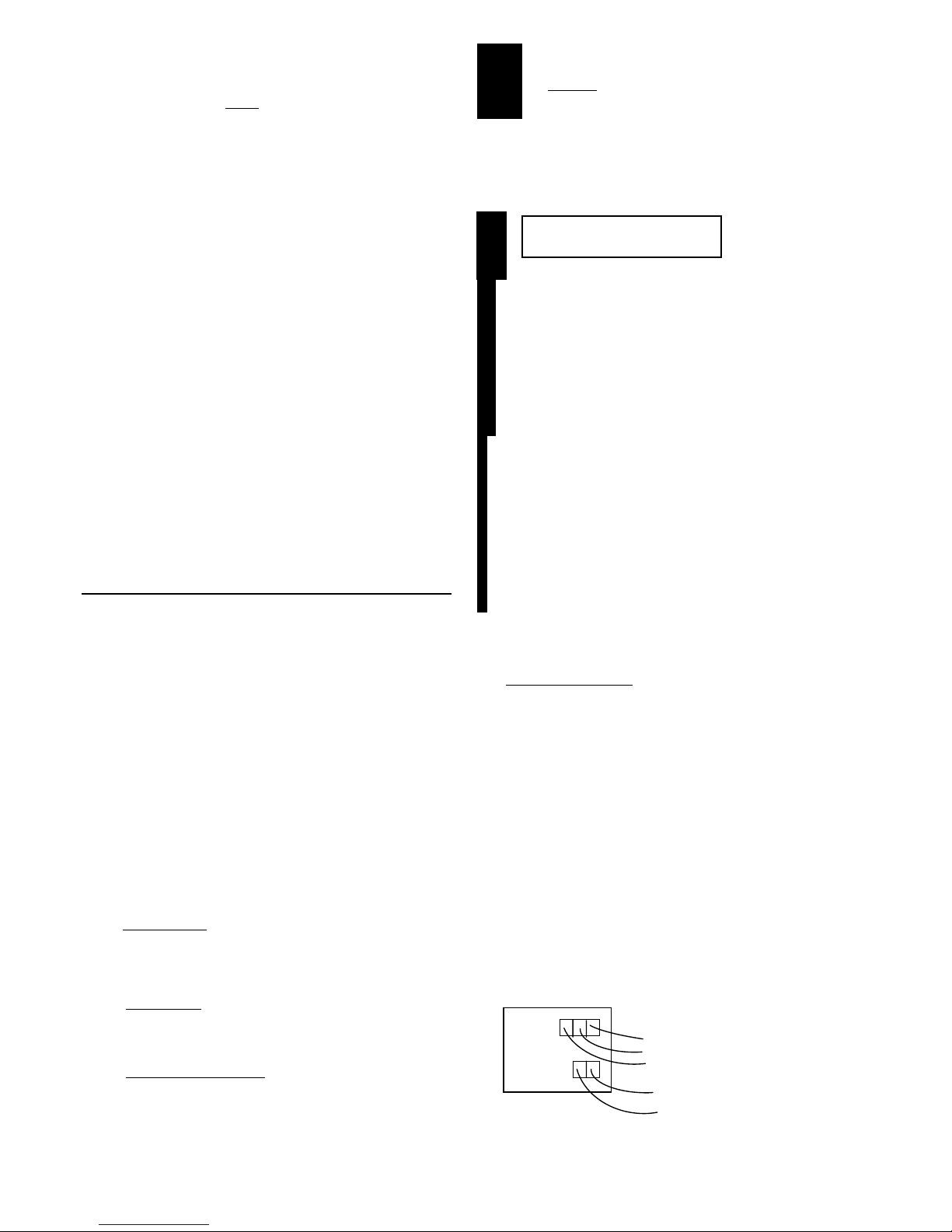
Connect the video output of the camera (yellow line) to a Color
monitor (EB220) or a color monitor (EM200), or other video device
through a 75 ohm type coaxial cable with BNC female
connector at cable extensi on.
Connect the DC+12V regulated power source of the camera (red
line) to the DC12V Power-in jack with 2mm, center+, outer- plug.
Connect the ground of the camera (black line) to the ground.
Connect the audio output line of the camera (white line) to the
audio connector of the monitor.

EB220/200 Series
INSTRUCTION
MANUAL
1/3" Metal Case Cameras
II. Precautions
• Do not expose the camera to humidity and dust . Outdoor
application without shielding is not recommended.
• Handle with care. This camera consists of high sensitive parts.
Do not disassemble it or place it on an unstable base.
• Do not touch the surface of CCD sensor by hand directly. When
the camera is not in use, put the cover cap on the lens.
• Operate on DC +12V (Use a regulated power source only).
• Never face the camera toward the sun.
IV. Specifications
MEM1G00100
The EB220 & EM200 Series Camera are compact, full
functioned CCD Camera. Their stylish appearance can be
applied as per installer's ideal locations. These metal case
camera can be mounted either on the ceiling or on the wall
easily. EB220 uses high sensitive 1/3" Color interline transfer
CCD sensor and EM200 uses high sensitive 1/3" color interline
transfer CCD sensor. Both cameras are featu r ed with Auto
Electronic Shutter, Automatic Gain Control, and EM200
includes Auto White Balance function.
I. General
EB220 EM200
Pickup Device: 1/3 inch Color interline 1/3 inch Color
transfer CCD interlin e t ra nsfer CCD
Picture Element: 510 x 492 (EIA) 510 x 492 (NTSC)
500 x 580 (CCIR) 500 x 580 (PAL)
Horizontal resolution: 420 TV lines (EIA) 380 TV lines (NTSC)
400 TV lines (CCIR) 340 TV lines (PAL)
Sensitivity: 0.04 lux/F=2.0 2.5 lux/F=2.0
S/N ratio: Over 48 dB Over 48dB
Electronic shutter: Up to 1/100,000 Up to 1/100,000
Gamma Correction: > 0.45 0.45
Video output: 1.0Vp-p,75 ohm 1.0Vp-p,75 ohm
Power source: 12VDC+/-10%, 12VDC+/-10%,
150mA Max. 250mA Max.
Sync. Mode: Internal Sync. Internal Sync.
Lens Mount: M12 x P0.5 M12 x P0.5
Operating Temperature: -10
o
C to +50oC-10
o
C to +50oC
III. Installation Instruc t io ns
Decide the location to install the metal case camera. The horizontal
view angle of the metal case camera with 3.6mm lens is
92-degree.
In application, the metal case camera can be installed as the
following four positions :
1) Ceiling mount
2) Floor mount
3) Wall mount, aim to right
4) Wall mount, aim to left
In order to get the correct picture, please always please keep
the cable connector on the bottom side.
1) Ceiling Mount :
The metal case camera are set in th e actual position
when the shipment is made. They are ready to be
installed.
2) Floor Mount :
Rotate the metal case in 180-degree so that the
connector is on the bottom side.
3) Wall Mount, aim to right :
Remove the metal case from the supporting bracket
by using screw driver to loosen the two screws,
which connect the case to the br acket. Turn the
metal case in 90-degree and mount into the supporting
bracket again by changing the screw holes in order to
keep the screw indicator on the bottom side.
4) Wall Mount, aim to left:
Remove the metal case from the supporting bracket
by using screw driver to loosen the two screws, which
connect the iron case to the supportin g br acket. Turn
the metal case in 90-degree and mount into the supporting
bracket again by changing the screw holes in order to keep
the screw indicator on the bottom side.
Connect the video output of the camera (yellow line) to a Color
monitor (EB220) or a color monitor (EM200), or other video device
through a 75 ohm type coaxial cable with BNC female
connector at cable extensi on.
Connect the DC+12V regulated power source of the camera (red
line) to the DC12V Power-in jack with 2mm, center+, outer- plug.
Connect the ground of the camera (black line) to the ground.
Connect the audio output line of the camera (white line) to the
audio connector of the monitor.
 Loading...