

EverFocus ELR-4, ELR-8 Instruction Manual
Instruction Manual
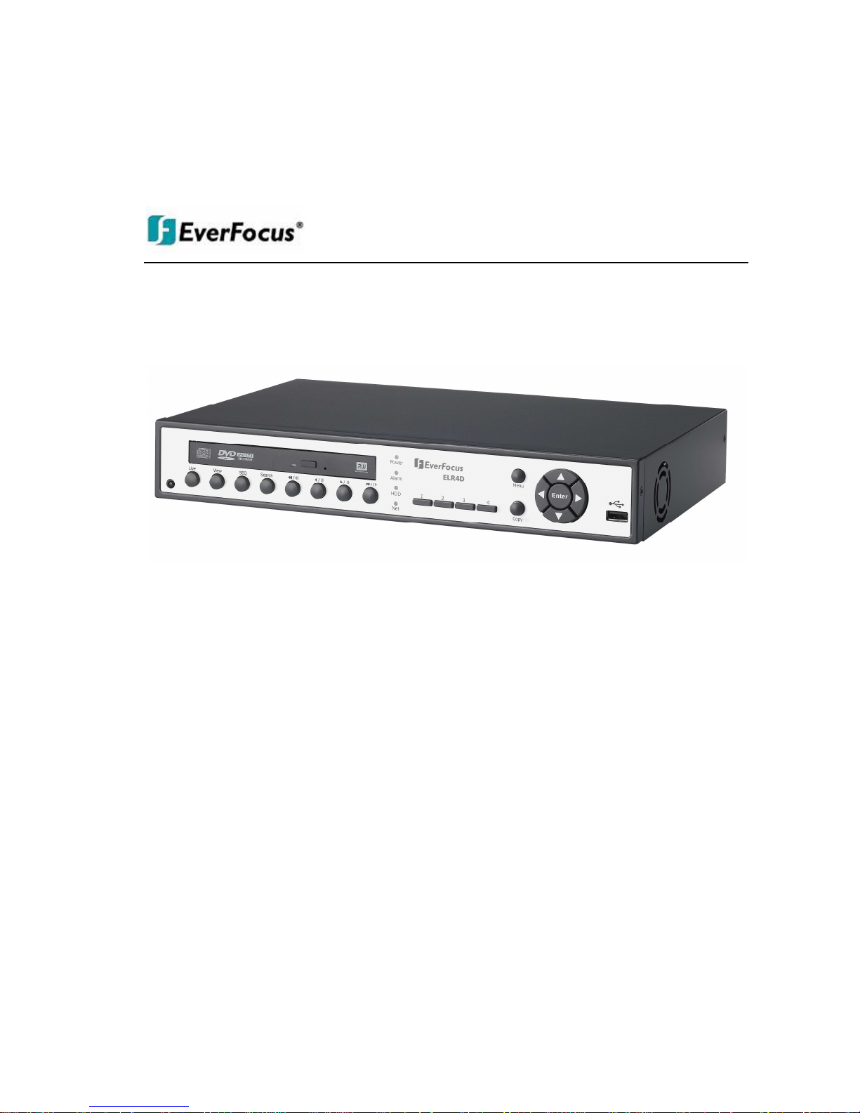
EELLRR--44//EELLRR--88

EVERFOCUS ELECTRONICS CORPORATION
ELR Series
Instruction Manual
2009 EverFocus Electronics Corp
www.everfocus.com
All rights reserved. No part of the contents of this manual may be reproduced or transmitted in any form or by
any means without written permission of the Everfocus Electronics Corporation.
Release Date: Aug. 2009
QuickTime is a registered trademark of the Apple Computer, Inc.
Windows is a registered trademark of the Microsoft Corporation.
Linksys is a registered trademark of the Linksys Corporation.
D-Link is a registered trademark of the D-Link Corporation.
DynDNS is a registered trademark of the DynDNS.org Corporation.
Other product and company names mentioned herein may be the trademarks of their respective owners.
ii
iiii
ii
Safety Precautions
• To avoid any damage, please consider the following safety warnings:
• Never place the recorder near to heaters, furnaces, other heat sources or under direct solar irradiation.
• Operate the device only in locations providing the tolerable operating temperature range
0°C~40°C/32°F ~ +104°F.
• Make sure that the device‘s ventilation slots are not covered or sheeted.
• For cleaning, make sure the device is plugged off and only use a damp cloth without acid detergent.
• Install the device only in dry and dustproof surroundings. Protect the device against any liquid‘s
penetration.
• Avoid the penetration of any artifacts, e.g. through ventilation slots.
• Do not attempt to disassemble the appliance. To prevent electric shock, do not remove screws or
covers. There are no user-serviceable parts inside. Contact qualified service personnel for maintenance.
Handle the appliance with care. Do not strike or shake, as this may damage the appliance.
• Do not operate appliance with other than specified power supplies. The input power source of the power
supply is 12 VDC.
• Avoid any affection of the device through vibrations or mechanical shock at the recorder‘s installation
location.
• Avoid to power off DVR during playback or recording operation.
ATTENTION!
This is a class A product which may cause radio interference in a domestic environment; in
this case, the user may be urged to take adequate measures.
Federal Communication Commission Interference Statement
This equipment has been tested and found to comply with the limits for a Class B digital device, pursuant to
Part 15 of the FCC Rules. These limits are designed to provide reasonable protection against harmful
interference in a residential installation. This equipment generates, uses and can radiate radio frequency
energy and, if not installed and used in accordance with the instructions, may cause harmful interference to
radio communications. However, there is no guarantee that interference will not occur in a particular
installation. If this equipment does cause harmful interference to radio or television reception, which can be
determined by turning the equipment off and on, the user is encouraged to try to correct the interference by
one of the following measures :
•Reorient or relocate the receiving antenna.
•Increase the separation between the equipment and receiver.
•Connect the equipment into an outlet on a circuit different from that to which the receiver is connected.
•Consult the dealer or an experienced radio/TV technician for help.
FCC Caution: Any changes or modifications not expressly approved by the party responsible for compliance
could void the users’ authority to operate this equipment.
iii
iiiiii
iii
This Product is RoHS compliant.
WEEE
The information in this manual was current upon publication. The manufacturer reserves the right to revise and improve his products.
Therefore, all specifications are subject to change without prior notice. Misprints reserved.
Please read this manual carefully before installing and using this unit. Be sure to keep it handy for later reference.

iv
iviv
iv
TABLE OF CONTENTS
1 PRODUCT OVERVIEW..................................................................................................... 1
1.1 FEATURES....................................................................................................................... 1
1.2 PACKAGE CONTENTS................................................................................................... 2
1.3 SPECIFICATIONS ........................................................................................................... 3
1.4 FRONT PANEL ................................................................................................................ 4
1.5 REAR PANEL................................................................................................................... 6
2 INSTALLATION.................................................................................................................. 8
2.1 COVERT INSTALLATION .............................................................................................8
2.2 VIDEO INPUTS/OUTPUTS INSTALLATION............................................................. 10
2.3 AUDIO INSTALLATION .............................................................................................. 10
2.4 ALARM CONTACTS INSTALLATION....................................................................... 10
2.4.1 Alarm Input Contacts ............................................................................................................................11
2.4.2 Control Input Contact ...........................................................................................................................11
2.4.3 Alarm Output Relay...............................................................................................................................12
2.5 RS-485
KEYBOARD /
PTZ I
NSTALLATION
......................................................................... 12
2.5.1 General RS-485 bus installation ...........................................................................................................12
2.5.2 RS-485 socket pin assignment ...............................................................................................................14
2.5.3 EKB-500 connection with network patch cable.....................................................................................14
2.5.4 EKB-500 connection to several DVRs...................................................................................................14
2.5.5 Speed Dome Installation .......................................................................................................................14
2.6 USB-M
OUSE INSTALLATION
............................................................................................ 15
2.7 NETWORK CONNECTION .......................................................................................... 15
2.7.1 Direct PC Connection through Crossover Network Cable ...................................................................15
2.7.2 Network Connection through Patch Cable............................................................................................16
2.8 FINAL INSTALL PROCESS.......................................................................................... 17
3 MOUSE AND FRONT PANEL OPERATION ............................................................... 18
3.1 GENERAL USB MOUSE OPERATION....................................................................... 18
3.1.1 How to select a channel / Enable audio................................................................................................18
3.1.2 OSD Root Menu ....................................................................................................................................18
3.1.3 Operation in Configuration Menu.........................................................................................................18
3.1.4 Component Options...............................................................................................................................19
3.2 GENERAL FRONT PANEL OPERATION................................................................... 21
3.2.1 How to select a channel / Enable audio................................................................................................21
3.2.2 OSD Root Menu ....................................................................................................................................21
3.2.3 Front Panel Key Review........................................................................................................................21
3.2.4 Operation in Configuration Menu.........................................................................................................21
3.2.5 Component Options...............................................................................................................................22
4 GENERAL DVR OPERATIONS...................................................................................... 24
4.1 RECORD......................................................................................................................... 24

vvvv
4.2 LOGIN............................................................................................................................. 24
4.3 SELECT CAMERA OPERATION................................................................................. 25
4.4 CHANGE AUDIO OUTPUT OPERATION.................................................................. 25
4.5 PLAYBACK.................................................................................................................... 25
4.6 PTZ.................................................................................................................................. 27
4.6.1 General PTZ control .............................................................................................................................27
4.6.2 Express control PTZ..............................................................................................................................28
4.7 LAYOUT......................................................................................................................... 30
4.7.1 Bring to full screen mode ......................................................................................................................30
4.8 CHANNEL SWITCHING............................................................................................... 30
4.9 DISPLAY ........................................................................................................................ 31
4.10 SEQUENCE.................................................................................................................. 31
4.11 ZOOM........................................................................................................................... 31
4.12 SEARCH....................................................................................................................... 32
4.12.1 Time Search...........................................................................................................................................33
4.12.2 Event Search..........................................................................................................................................34
4.13 COPY............................................................................................................................ 36
4.14 LOGOUT...................................................................................................................... 37
5 DVR CONFIGURATION.................................................................................................. 38
5.1 CONFIGURATION MENU............................................................................................ 38
5.2 EXPRESS........................................................................................................................ 38
5.3 CAMERA SETTING ...................................................................................................... 40
5.3.1 Basic Setting..........................................................................................................................................41
5.3.2 Video Adjust ..........................................................................................................................................43
5.3.3 Motion ...................................................................................................................................................44
5.3.4 Video Loss.............................................................................................................................................47
5.4 RECORD & PLAY SETTING........................................................................................ 48
5.4.1 Record ...................................................................................................................................................48
5.4.2 Built-in Cal............................................................................................................................................49
5.4.3 Play .......................................................................................................................................................50
5.5 ALARM & EVENT SETTING....................................................................................... 51
5.5.1 Alarm.....................................................................................................................................................51
5.5.2 Event......................................................................................................................................................53
5.6 SCHEDULE SETTING................................................................................................... 60
5.6.1 Express Setup ........................................................................................................................................60
5.6.2 Holidays ................................................................................................................................................61
5.6.3 Schedule ................................................................................................................................................62
5.6.4 Alarm Action .........................................................................................................................................67
5.7 NETWORK SETTING.................................................................................................... 71
5.7.1 LAN .......................................................................................................................................................71
5.7.2 EMAIL...................................................................................................................................................72
5.7.3 DDNS ....................................................................................................................................................73
5.7.4 Alarm Server .........................................................................................................................................75
5.8 D
ISK SETTING
................................................................................................................... 76
5.8.1 Disk .......................................................................................................................................................76
5.9 DISPLAY SETTING....................................................................................................... 77
5.9.1 Monitor OSD.........................................................................................................................................77

vi
vivi
vi
5.9.2 Main M/T SEQ ......................................................................................................................................78
5.10 SYSTEM SETTING..................................................................................................... 79
5.10.1 Date/Time..............................................................................................................................................79
5.10.2 Daylight Saving.....................................................................................................................................80
5.10.3 User.......................................................................................................................................................81
5.10.4 I/O Control............................................................................................................................................83
5.10.5 Misc.......................................................................................................................................................84
5.11 INFORMATION SETTING......................................................................................... 85
5.11.1 System....................................................................................................................................................85
5.11.2 Log.........................................................................................................................................................86
6 NETWORKING OVERVIEW.......................................................................................... 88
6.1 I
NTRODUCTION TO
TCP/IP............................................................................................... 88
6.2 S
UBNET MASKS
................................................................................................................ 88
6.3 G
ATEWAY ADDRESS
......................................................................................................... 88
6.4 V
IRTUAL PORTS
................................................................................................................ 89
6.5 PRE-I
NSTALLATION
.......................................................................................................... 89
6.6 W
HAT IS YOUR NETWORK SETUP
?.................................................................................... 90
6.7 S
IMPLE ONE TO ONE CONNECTION
................................................................................... 91
6.8 D
IRECT HIGH SPEED MODEM CONNECTION
..................................................................... 96
6.9 R
OUTER OR
LAN C
ONNECTION
........................................................................................ 98
7 REMOTE OPERATION FROM BROWSER............................................................... 101
7.1 CONNECTING TO ELR .............................................................................................. 101
7.2 BROWSER SECURITY SETTING .................................................................................. 102
7.2.1 Installing ActiveX controls ..................................................................................................................102
7.2.2 Enabling ActiveX Controls..................................................................................................................104
7.3 REMOTE LIVE VIEW................................................................................................. 107
7.4 REMOTE PLAYBACK................................................................................................ 108
8 EVERFOCUS DDNS SETUP.......................................................................................... 109
9 LINKSYS & D-LINK PORT FORWARDING ............................................................. 110
9.1 LINKSYS PORT FORWARDING............................................................................... 110
9.2 D-LINK PORT FORWARDING.................................................................................. 112
10 TROUBLESHOOTING ................................................................................................ 115
APPENDIX A: TIMING OF ALARM MODES.................................................................... 116
APPENDIX B: CHANGING RULE FOR EXPRESS SETUP............................................. 119

1
1 PRODUCT OVERVIEW
The latest EverFocus digital video recorder generation is based on H.264 compression technology,
resulting in enhanced recording capacity and improved network image transmission speed with high image
quality. Comprehensive features and extended event recording settings enable the almost universal
application of this DVR series. The ELR Series DVR comes with multiple control inputs. These inputs
include mouse control, front panel control, IR remote control and EverFocus keyboard (EKB500) control.
Mouse control is supported with the simple Graphical User Interface (GUI), offering experienced PC users
the similarity of interactive command of a computer-controlled device. With the GUI, users can command
specific actions on the ELR Series DVR through graphical icons and visual indicators. Simply point, click
and drag the playback bar on the screen to playback our recordings in any time slot. All GUI functions can
be operated via front panel or mouse. Hop on the Express Lane! The ELR series DVR is engineered for
express operations. Setup, copy, search and playback recordings in seconds with a simple “point and click”
on the command icons.
1.1 FEATURES
• H.264 Compression format
• Pentaplex Operation (Simultaneous live, recording, playback, archiving and remote viewing)
• User friendly GUI with graphical icons and visual indicators
• Free EverFocus DDNS Service
• Multiple Control Inputs: mouse/front panel/remote control
• Built-in DVR calculator for fast recording estimation
• Express Setup: Located in menu option for quick & easy installation
• Remote configuration support from built-in web interface
• Audio recording capabilities
• Support 1 internal SATA HDD
• Built-in DVD burner(Optional)
• 1 USB 2.0 ports on front panel for video archive and mouse usage
• Multi-language support
Chapter
1

2
1.2 PACKAGE CONTENTS
Digital Video Recorder x1
User’s Manual Disk x1
AC Adapter and Power Cord x1
Hard Drive Rack Mount x1
SATA Connection Cable x1
Pack of screws x 1
* marked accessories not included in some models

3
1.3 SPECIFICATIONS
Channel Number 4 8
Compression Format H.264
Recording Rate/Resolution
120 NTSC / 100 PAL (CIF)
60 NTSC / 50 PAL (Half D1)
30 NTSC / 25 PAL (D1)
120 NTSC / 100 PAL (CIF)
60 NTSC / 50 PAL (Half D1)
30 NTSC / 25 PAL (D1)
Playback Rate/Resolution
120 NTSC / 100 PAL (CIF)
60 NTSC / 50 PAL (Half D1)
30 NTSC / 25 PAL (D1)
120 NTSC / 100 PAL (CIF)
60 NTSC / 50 PAL (Half D1)
30 NTSC / 25 PAL (D1)
Pentaplex Operation Simultaneous Live, Recording, Playback, Archive and Remote Viewing
Video Input/Output 4/Main, VGA 8/Main, VGA
Audio Input/Output 1 Input / 1 Output
Recording Mode Manual, Schedule and Event
Playback Search By Date/Time and Event
Alarm In 4 Inputs 8 Inputs
Alarm Out 1 Alarm Outputs
Video Pause Yes
Video Loss Detection Yes
Motion Detection Yes
Event Log Yes
Watch Dog Timer Yes
Internal HDD 1
Built-in DVD Burner Slim Type DVD Burner(Optional)
User Interface GUI(Graphical User Interface)
OS Embedded Linux
Network/Protocol 10/100Mbps Ethernet; TCP-IP / DHCP/ PPPoE / Everfocus DDNS
USB 1 USB 2.0 on Front Panel
Schedule Setting Support Express and Advanced Schedule Setting
User Access 3 Levels of User Access Support
RS-232 No
RS-485 Terminal connector
Power Source 12VDC
Dimensions (L x W x H) 320 x 208.9 x 54.3 mm / 12.6" x 8.2" x 2.1"
Temperature 0°C~40°C / 32°F~104°F (20~80% humidity)
Support PTZ Protocol EverFocus, Pelco D, Pelco P, Samsung, Transparent
4
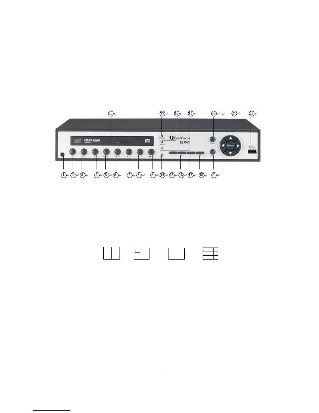
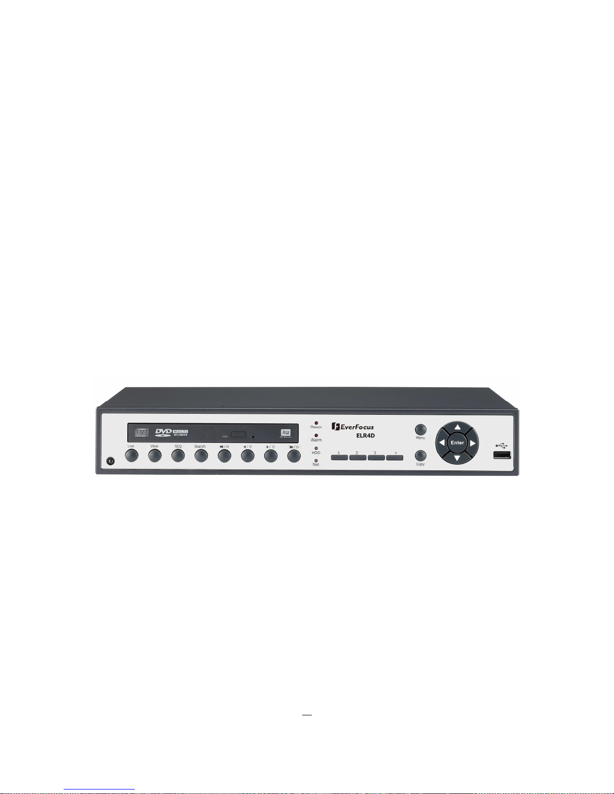
1.4 FRONT PANEL
Your primary interaction with your new DVR will be through the Front Panel buttons and their
corresponding buttons on the included Remote Control. Take a moment to learn where the keys are as the
remainder of the manual will refer to them often.
Figure 1-1 Front Panel
1) IR Receiver: Receiver for IR remote control
2) Live: Press this key to show live view. Press to exit from playback mode.
3) View: Press this key to switch between 4x, PiP (Picture In Picture), full screen and 9x.
Examples of four different views are listed below:
4x PiP Full screen 9x
Note1: PIP display is not available in playback mode.
Note2: 9-screen display available in 8 Channel model only.
4) SEQ: Press this key to enter the auto sequential switching mode. The sequence dwell
time can be set in “Display Setting” tab of the Menu. For more detail about SEQ,
please see “5.9.2 Display Setting-Main M/T SEQ”.

5
5) SEARCH: Press this key to enter Search Menu. For more detail about Search function,
please see “4.12 Search ”.
6) ◄◄/◄I: Fast reverse playback or step reverse playback depending on playback mode.
7) ◄/ I I: Reverse playback or pause
8) ►/ I I: Forward playback or pause
9) ►►/I►: Fast Forward playback or step forward playback depending on playback mode.
10) DVD+RW: DVD+RW burner (D models only)
11) POWER LED: This LED ON indicates Power active.
12) ALARM LED: This LED ON indicates Alarm active.
13) HDD LED: This LED ON indicates HDD active.
14) Net LED: This LED ON indicates Network active.
15~18) Channel keys 1~4 (1~8): Press channel key (CH1~CH4) / (CH1~CH8) to display that channel in
full screen view.
19) MENU: Press this key to enter/exit MAIN SETUP MENU.
20) COPY: Press this key to enter Copy Menu. For more detail about Copy function, please
see “4.13 Copy”.
21) ENTER/ ARROW keys: If you do not use a mouse, you can use these keys to change the Menu
settings.
22) USB port: For connecting USB mouse or USB-Flash-Drive.
6
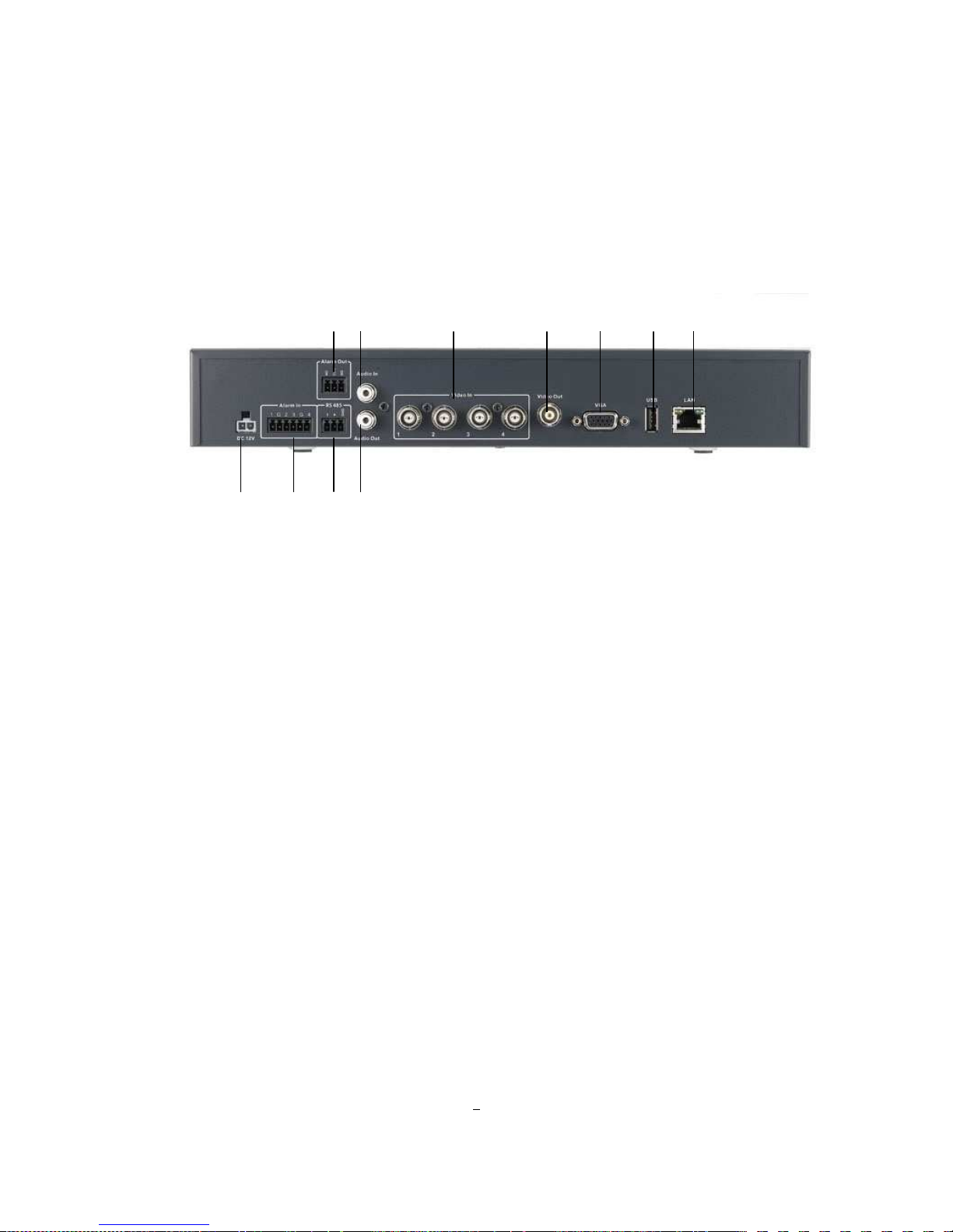
1.5 REAR PANEL
During initial setup you will be connecting your DVR to multiple input and output devices. This is done
through the rear panel.
Figure 1-2 Rear Panel
○○○○1 POWER: Plug the DC 12V power source into the power socket.
○○○○2 Alarm In: Connect up to 4 alarm inputs, selectable between dry contact or TTL/CMOS signal
polarity.
○○○○
3
Alarm Out: N.C or N.O type alarm signal out.
○○○○4 RS485 socket: For remote control via RS-485 keyboards and telemetry control
○○○○5 Audio In: Connect a microphone or camera audio output to the audio input connection.
○○○○6 Audio Out: Connect a speaker or other audio listening devices to the audio output connection on
the back of the digital video recorder.
○○○○7 Video In: Connect camera’s video output or other composite video source to the video input
connection.
○○○○8 Video Out: Connect a CCTV monitor to the video output connection.
○○○○9 VGA: Connect a VGA monitor to the VGA output connection.
○○○○10 USB 2.0: USB port allows you to archive video files to USB flash memory device or to connect
the mouse.
○
1
○
2
○
3
○
9
○
4
○
6
○
5
○
7
○
8
○
10
○
11

7
○○○○11 LAN: RJ-45 network connection
8
2 INSTALLATION
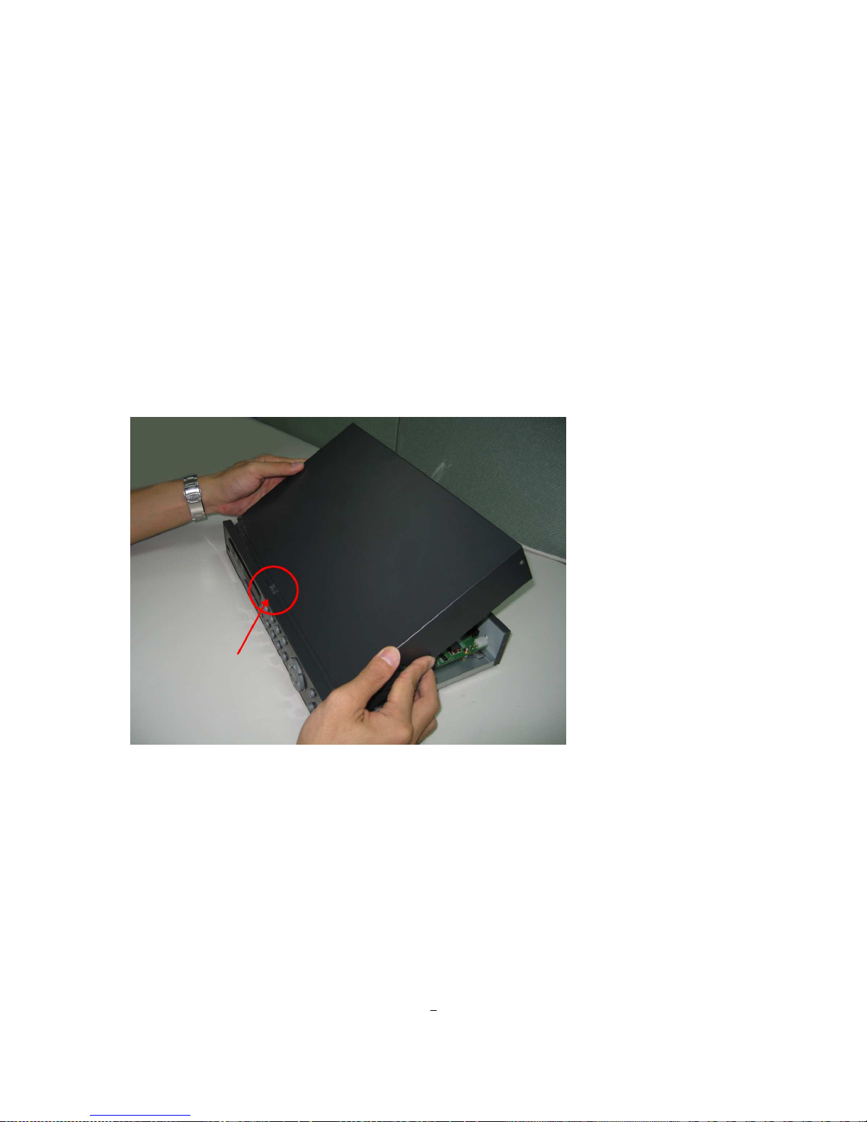
2.1 COVERT INSTALLATION
1. Aim the small rectangular hole of the covert to the protrudent part of the front panel. Please see diagram
2.1.
Diagram 2.1
Chapter
2
9
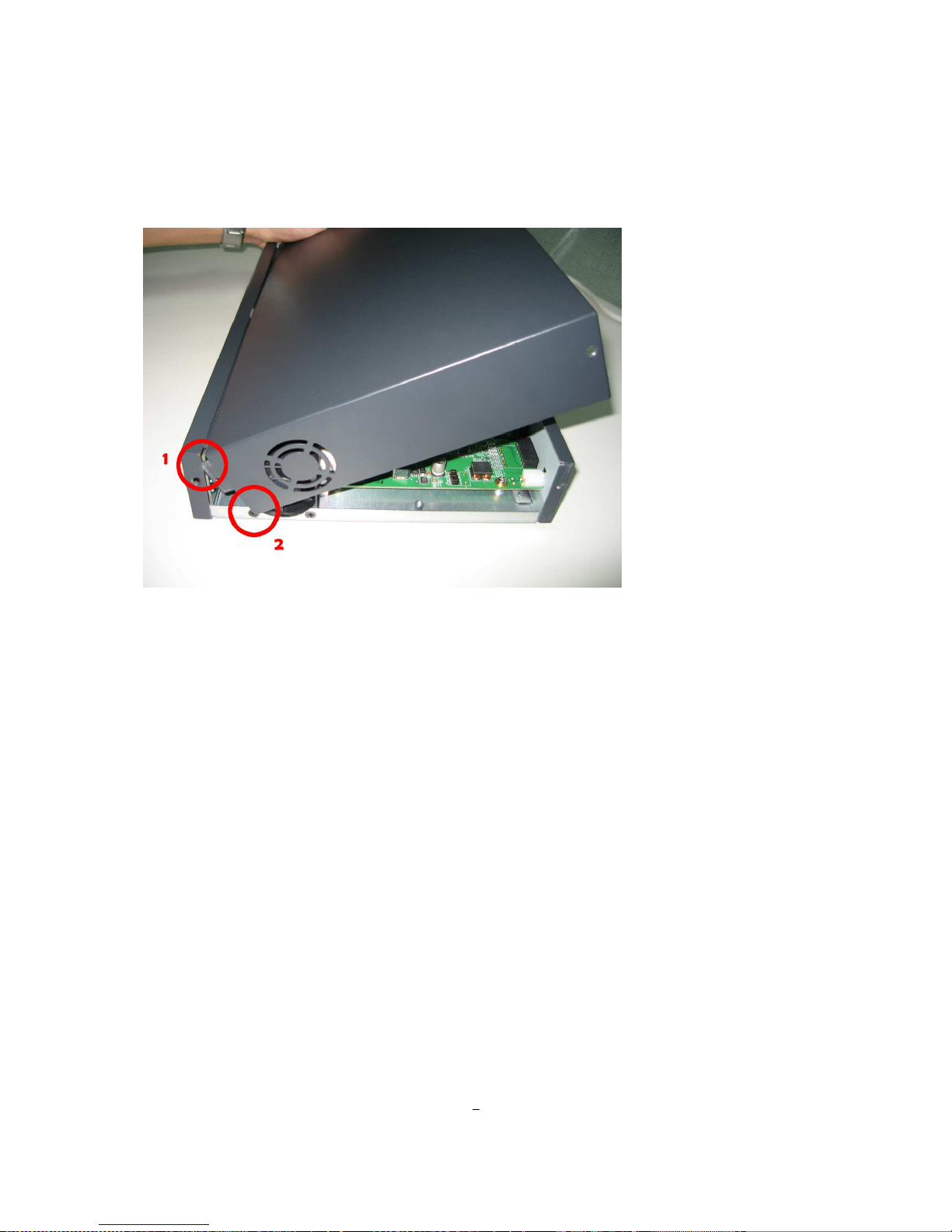
2. Please see diagram 2.2 first. Make sure to have part 1 inserted inside the front panel, and part 2 has to
stay outside the base. Finally, fix the covert firmly.
Diagram 2.2

10
2.2 VIDEO INPUTS/OUTPUTS INSTALLATION
Camera and CCTV monitor must use 75 Ohm video cable (e.g. RG-59, RG-6, RG-11) with BNC connectors.
Due to inappropriate absorbability, 50 Ohm coax cable (e.g. RG-58), antenna cable and other types of
coaxial cable are not compatible.
All connected video sources must provide a 1 Vpp NTSC or PAL standard video signal.
When converting transmission lines (twisted pair, fibre optics, radio) to the video inputs, be sure to verify
accurate receiver calibration.
ATTENTION: In order for the system to auto-detect the appropriate video format (NTSC or PAL), make
sure that there is a video signal on video input 1 upon power-up.
2.3 AUDIO INSTALLATION
The ELR DVR provides 1 audio input and 1 audio output.
The input is designed for max. 500 mV to 10 KOhm line audio signals.
ATTENTION: The direct connection of a non-amplified microphone is not supported (a microphone
amplifier is required).
The installation must be done with audio coax cable and RCA plugs.
The output provides a max. 500 mV to 10 KOhm line audio signal and may be connected to a monitor‘s
audio input. The direct connection of passive speakers is not supported.
AUDIO RECORDING FUNCTIONALITY:
Audio recording is activated / deactivated in the RECORD menu.
Audio channel is always recorded together with video and is independent of the image recording rate.
There is no specific camera allocation.
2.4 ALARM CONTACTS INSTALLATION
The ELR alarm inputs can be used for recording start or recording rate adjustment. Furthermore, alarm
reactions such as camera switching to monitors, buzzer, e-mail and network alarm are available. 4 alarm
output relays can be switched if required.
Additionally the ELR DVR provides 4 x TTL - level control outputs with similar functionality as the relay
outputs.
11
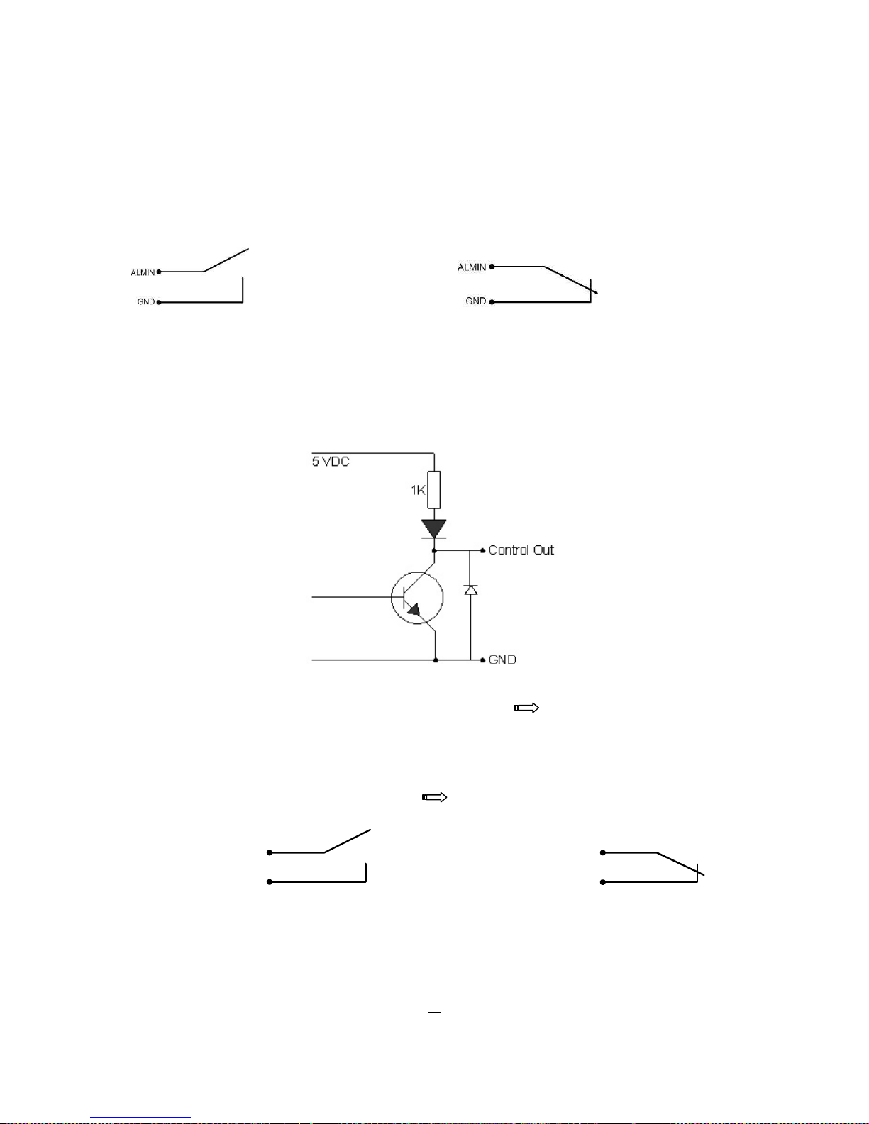
2.4.1 Alarm Input Contacts
ELR4 provides 4/8 alarm inputs. All inputs are programmable N.O. (Normal Open) or N.C. (Normal Closed)
Inputs have to be switched by dry contacts.
Alarm input with N.O. (Normal Open) contact Alarm input with N.C. (Normal Closed) contact
in idle state in idle state
All settings are programmed in the ALARM menu (chapter 5.5.1).
2.4.2 Control Input Contact
The Control Input CTRL IN is a N.O. (Normal Open) contact. Changing to N.C. is not possible.
Control Input relay in idle state
The Control Input Contact CTRL IN is defined in I/O Control menu ( chapter 5.10.4) for following
possible functions:
1. Playback: Playback is active as long the contact is closed. This function is helpful in
combination with the "Quickplay" function ( chapter 5.4.3)
CTRL IN
GND
CTRL IN
GND
Idle state Playback

12
2. Record: The input switches to Record (or Record Standby) as long the contact is closed.
CTRL IN
GND
CTRL IN
GND
Idle state Record / Record Standby
3. Armed / Disarmed: If the contact is closed, the DVR will switch off alarm (alarm contact and motion
alarm) operation. System alarm events are always active.
CTRL IN
GND
CTRL IN
GND
DVR armed DVR disarmed
2.4.3 Alarm Output Relay
The relay outputs provide either Normally Open or Normally Closed dry contacts.
Output relay in idle state
2.5 RS-485 keyboard / PTZ Installation
All ELR functions can be remote-controlled by the EKB-500 universal keyboard. Using the EEPbus protocol,
digital video recorders, keyboards and speed domes can be installed on one single RS-485 bus. One
system can comprise up to 8 keyboards.
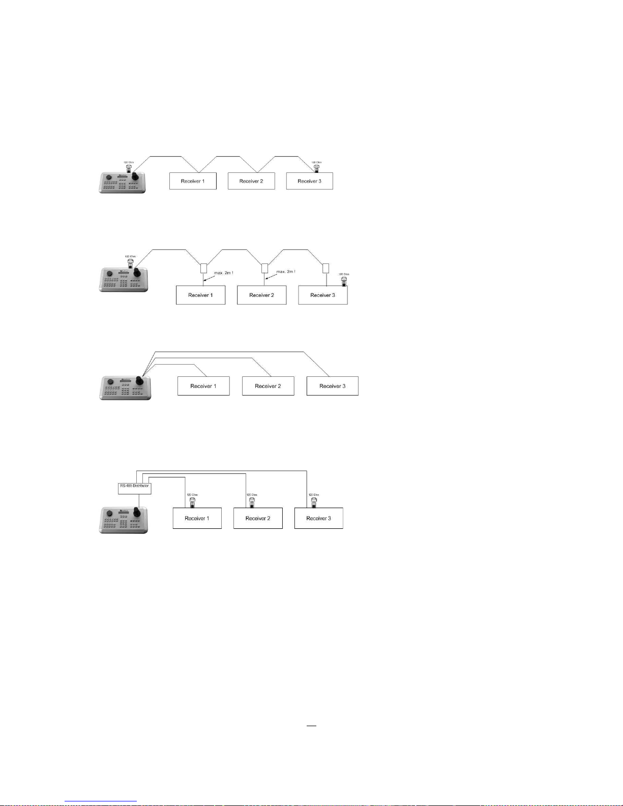
2.5.1 General RS-485 bus installation
The EKB-500 keyboard uses a RS-485 simplex wiring; the signal is transferred via a single twisted pair line.
CAT5 network cable is recommended, UPT version (unshielded) is sufficient for normal application. A
shielded cable should be used if the installed cables are expected to be highly susceptible to interferences.
The number of devices installed in one bus is limited to 32, and the maximum cable length is 1200m. Both
of these can be expanded using a signal distributor (see below).
13
Both the first and the last device in series should be terminated with 120 Ohm resistance in order to
minimize line reflections.
RS-485 bus serial wiring
Cable length from box to device („Stubs“) has to be limited to 2m using connector boxes.
RS-485 bus serial wiring with connector boxes and connection cable
A direct RS-485 bus star wiring is not supported unless using a signal distributor (see below).
Improper RS-485 bus star wiring
A RS-485 signal distributor may be used to use a star wiring configuration.
Star wiring with RS-485 signal distributor
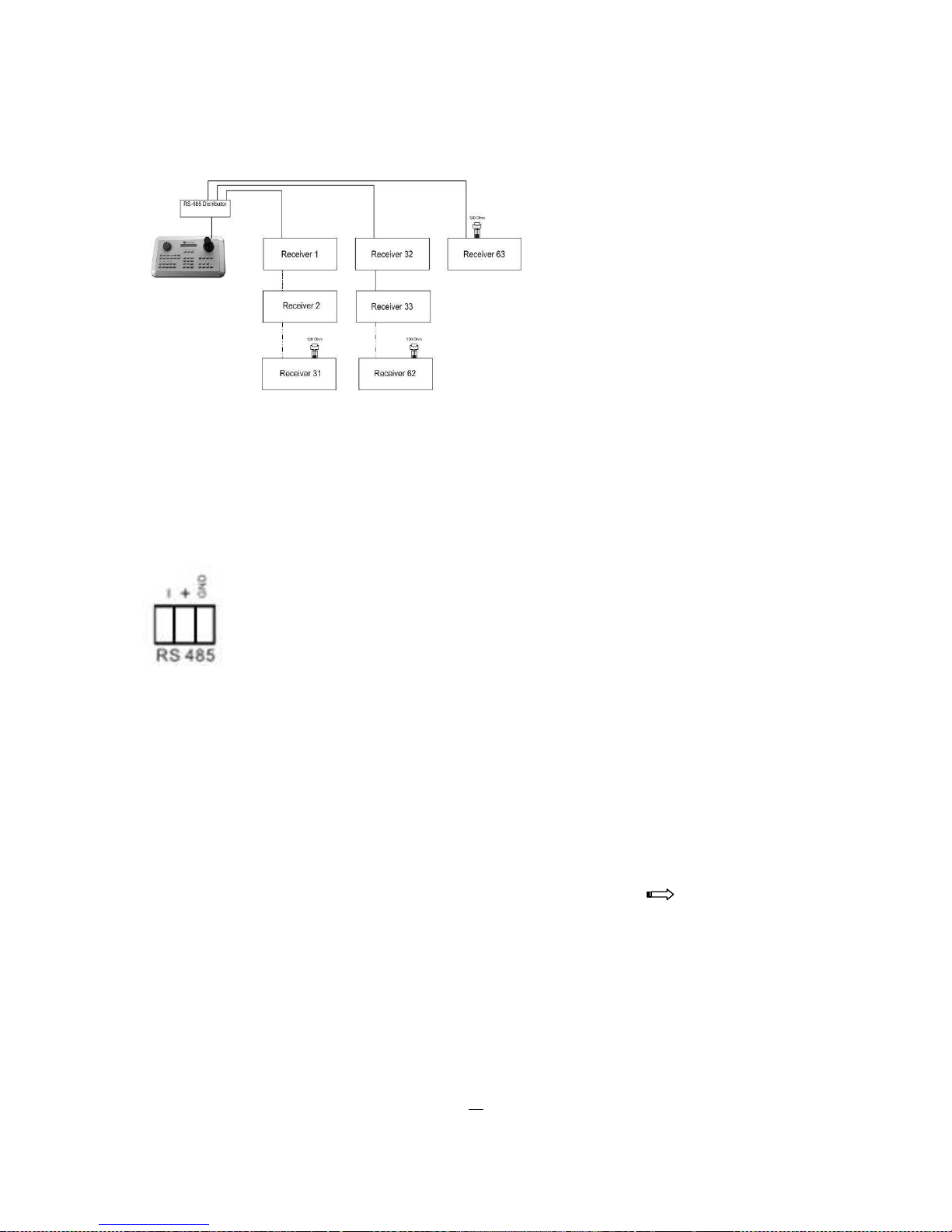
A RS-485 distributor can also be used to increase the maximum number of devices on the bus as well as
the total range. Each distributor output provides another RS-485 bus. This allows each output to extend an
additional 1200m, and it also enables the additional connection of 31 further devices to each output (the
output itself represents one device).
The maximum system expandability depends on the RS-485 address range of the installed devices.
14
System expansion with RS-485 signal distributor
ATTENTION: Most signal distributors are unidirectional! This means that the signal only flows from the
input towards the outputs. Therefore, e.g. the interconnection of several keyboards is not possible with
these types of signal distributor!
2.5.2 RS-485 socket pin assignment
The following RS485 pin assignment as follow:
2.5.3 EKB-500 connection with network patch cable
For a simple, short distance installation, recorder and keyboard can directly be connected using a standard
CAT5 network cable (patch cable, uncrossed!).
2.5.4 EKB-500 connection to several DVRs
For long distance installations connecting several DVRs, please use signal distributor to connect
For further details on keyboard connection, please refer to the EKB-500 manual.
RS-485 port communication settings are configured in the I/O CONTROL menu ( chapter 5.10.4
System Setup: I/O - control).
2.5.5 Speed Dome Installation
Speed dome or telemetry receiver pan/tilt/zoom control is available through web browser or the optional
PowerCon software if the DVR is connected to a network. Local telemetry control is provided by USB mouse control or by the optional EKB-500 keyboard.
15
Supported protocols: EverFocus, Pelco-D, Pelco-P, Samsung, Transparent
Required DVR settings: RS-485 receiver address in CAMERA menu
( chapter 5.3)
RS-485 parameters and protocol in the I/O CONTROL menu
( chapter 5.10.4.)
ATTENTION: Some Pelco-D / -P protocol domes and receivers require an address offset of -1, i.e. the
address assigned to the dome / receiver in the DVR camera menu must be 1 below the address set in the
dome / receiver itself!
2.6 USB-Mouse installation
Connect the USB mouse to one of the 2 USB ports. (This can be done while DVR is powered on)
NOTE: Recommended mouse types are Logitech® and Microsoft® wired USB wheel-mouse. Wireless
USB mouse is not supported.
2.7 NETWORK CONNECTION
This section only describes physical connection to an Ethernet network. This step must be completed
before the DVR’s can connect to the network. There are two basic types of connection:
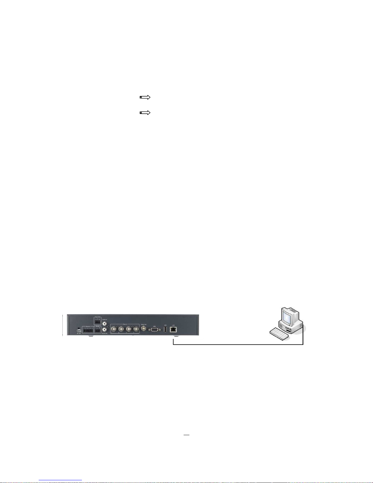
2.7.1 Direct PC Connection through Crossover Network Cable
The point-to-point connection of DVR and PC requires a crossover (crossed) network cable. This type of
connection is ONLY used for direct connection to a single PC. Make sure that the PC is equipped with a
10/100/1000 Mbps compatible network connection.
Figure 2-1 Direct PC Connection
16
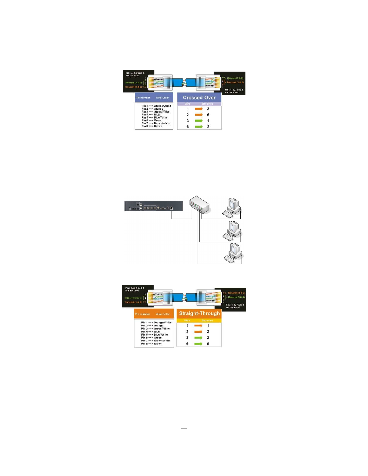
Pinout of crossover-cable
2.7.2 Network Connection through Patch Cable
The connection to an existing network requires a normal patch cable (straight-through). The illustration
shows the connection to a network switch, router, or modem.
Figure 2-2 Network Connection through Patch Cable
Pinout of straight patchcable

17
2.8 FINAL INSTALL PROCESS
Once you have completed the basic wiring connections, you are ready to turn on the DVR. Simply plug in
the power source. The POWER LED will light up if power is normal. Once the system has finished loading,
you can begin to set up the menu options for the DVR.
18
3 MOUSE AND FRONT PANEL OPERATION
ELR series DVR supports multiple sources to control the DVR. It can be controlled with a mouse, the front
panel, an EKB500, the handheld remote control.
This chapter will cover the basic operation using mouse and front panel.
3.1 GENERAL USB MOUSE OPERATION
3.1.1 How to select a channel / Enable audio
1. In a view consisting of more than one channel, user can select a channel by clicking once on desired
channel screen. The selected screen will be highlighted by white frame.
2. Double clicking on a channel screen will display full screen of this channel.
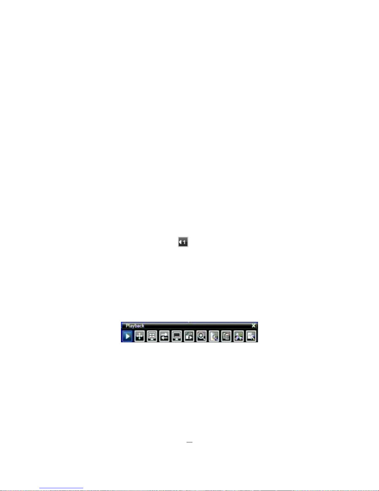
3. To enable audio out, click audio icon (ex: ) at lower side of the screen. This system can have
only one audio out for one camera at a time. Click this button to select a camera for audio out, or to
select none audio-out mode.
3.1.2 OSD Root Menu
1. Right-click the mouse to obtain DVR control bar (see Figure 3-1 OSD Root Menu ). When you move the
mouse over each icon, the appropriate title will be displayed on top of the control bar.
Figure 3-1 OSD Root Menu
2. Click on any icon to perform that action. These actions are covered in detail in Chapter 4.
3. Click the “X” in the top-right corner to close the DVR control bar.
3.1.3 Operation in Configuration Menu
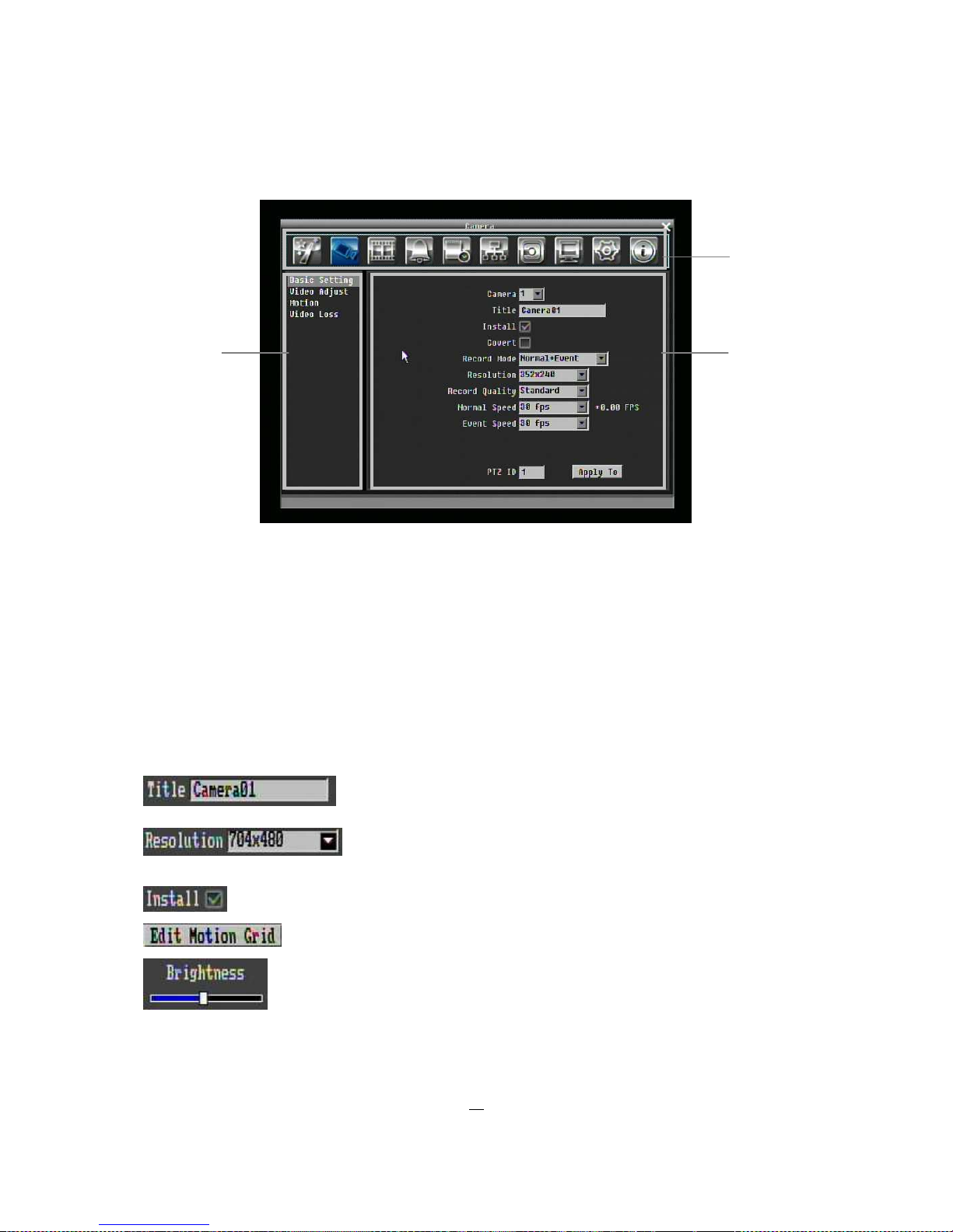
The Main menu (shown in Figure 3-2 OSD Menu) is divided into 3 main sections.
Chapter
3
19
Figure 3-2 OSD Menu
○1 In section 1, there are ten setup options available. Move the mouse over an icon and click to select it.
○2 In section 2, the categories for the selected icon will be displayed. Click on a word to select it.
○3 In section 3, all the details for the selected option will be available. Click on a field to make changes.
3.1.4 Component Options
The following are examples of different fields available in the Configuration menu.
Textbox: Click on the box and an on-screen keyboard will appear. (see
below)
Dropdown box: Click on the down arrow to see all selections, then
directly click on an option to select it.
Check box: Click on the box to enable it (checked) or disable it (unchecked).
Button: Click the button to execute the function.
Bar: Click and hold on the bar to adjust the cursor Left or Right.
○
1
○
3
○
2

20
* Note about on-screen keyboard:
Click on a button to input that character.
The buttons on the right and bottom have the following functions:
Delete Delete the letter
Done Confirm the selection
All Caps Switch to capital letters
Space Enter a space
← Move to left
→ Move to right
Cancel Cancel and exit from the keyboard
21
3.2 GENERAL FRONT PANEL OPERATION
3.2.1 How to select a channel / Enable audio
1. In a view consisting of more than one channel, use the mouse or press arrow keys
(Up/Down/Right/Left) to scroll through each channel that is displayed. The selected channel will be
highlighted by white frame.
2. While one channel is selected, click “Enter” button to turn Audio On/ Off.
3.2.2 OSD Root Menu
1. Press “Menu” key to obtain DVR control bar. Use Jog or Shuttle to scroll over each icon. The title for
each icon will be displayed on top of the control bar.
2. Press “Enter” key on any icon to perform that action. These actions are covered in detail in Chapter 4
3. Press “Menu” to close the DVR control bar.
3.2.3 Front Panel Key Review
The basic principle of front panel operation is to use arrow keys to navigate among the menu items. Use
“Enter” key to confirm a selection or enter the next level menu. Press “Menu” key to enter the Main Menu
or exit from the current level of the menu.
3.2.4 Operation in Configuration Menu
Press “Menu” and press “Enter” with “Configuration” icon highlighted to bring up Configuration menu.
NOTE: If password is active, you will need to log in first. Refer to “4.2 LOGIN” for information on logging in.
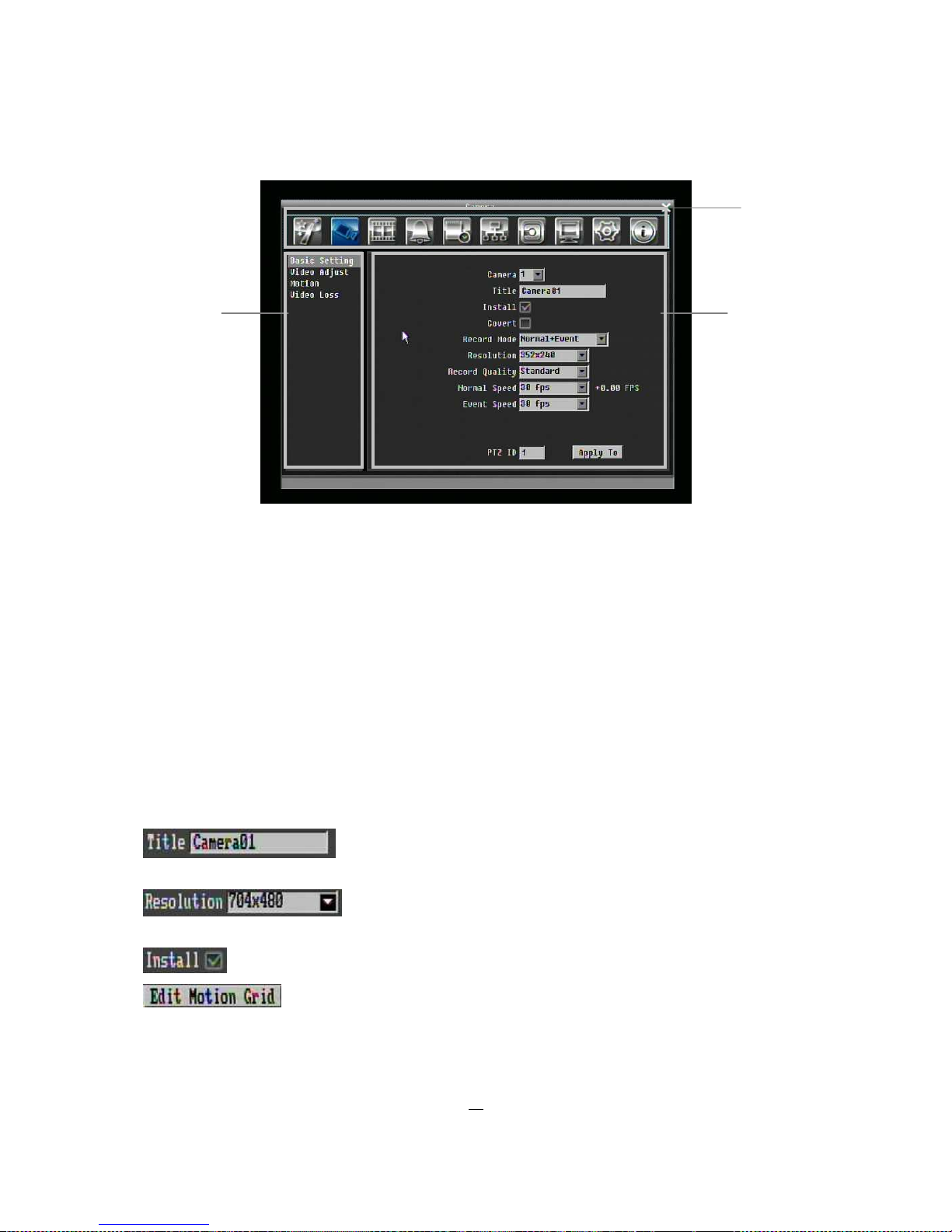
The menu (shown in
Figure 3-3 OSD Menu
) is divided into 3 main sections.
22
Figure 3-3 OSD Menu
○1 In section 1, there are ten setup options available. Use arrow keys to highlight an icon and press “Enter”
to select it.
○2 In section 2, the main options for the selected icon will be displayed. Use Up/Down arrow keys to
highlight an option and press “Enter” to select it.
○3 In section 3, all the details for the selected option will be available here. Use arrow keys to move
between items and press “Enter” to make changes.
Note: press “Menu” button to go back to the previous menu section.
3.2.5 Component Options
Textbox: Press Enter key and an on-screen keyboard will appear. (see
below)
Dropdown box: Press “Enter” key to show the available options. Use
arrow keys to highlight the desired option and press “Enter” again to select it.
Check box: Press “Enter” key on a setting to enable it (checked) or disable it (unchecked).
Button: Press “Enter” key to execute the function.
○
1
○
3
○
2

23
Bar: Press “Enter” key to activate the slider, then use arrow keys to adjust the setting.
Press “Enter” again to finalize the changes.
 Loading...