

Page 1
Multi-Function Keyboard Controller
EKB500
User’s Manual v1.13
Page 2

2
Table of Contents
1. INTRODUCTION
2. INSTALLATION
2.1. EKB500 KEYBOARD CONNECTION DIAGRAM..........................5
2.2. PACKING LIST.................................................................................5
2.3. Quick Installation and Operation Guide (Work with EPTZ1000).........6
3. FEATURE
4. SETTING
4.1. COM PORT SETTING..................................................................... 11
4.2. DEVICE SETTING..........................................................................12
4.2.1. Camera Setting..........................................................................12
4.2.2. Monitor Setting.........................................................................13
4.2.3. DVR Setting .............................................................................13
4.2.4. Camera List & Delete................................................................14
4.2.5. Monitor List & Delete...............................................................15
4.2.6. DVR List & Delete ...................................................................16
4.2.7. Non-listed Device .....................................................................17
4.3. KEYBOARD SETTING...................................................................17
...............................................................................................7
................................................................................................9
..................................................................................4
.....................................................................................5
4.3.1. Sub Keyboard Setting ...............................................................17
4.3.2. MENU Password ......................................................................18
4.3.3. Lock Password..........................................................................19
4.3.4. Alarm Password........................................................................20
4.3.5. Buzzer ON/OFF........................................................................21
4.3.6. Joystick Calibration...................................................................21
4.3.7. Keypad Test..............................................................................22
4.3.8. Jog & Shuttle Test.....................................................................22
4.3.9. Load default setting...................................................................23
4.3.10. Firmware update.......................................................................23
5. KEYBOARD FUNCTIONS
5.1. DVR support ....................................................................................24
5.2. Monitor support................................................................................26
5.3. Camera (Speed dome) support..........................................................26
6. DEVICE CONTROL OPERATION GUIDE
6.1. To operate a speed dome (EPTZ1000)...............................................29
6.1.1. Manual Control Mode...............................................................29
...............................................................24
...................................29
6.1.2. Auto Pan Mode.........................................................................30
Page 3

3
6.1.3. Position Setting.........................................................................31
6.1.4. Tour Mode ................................................................................ 32
6.1.5. Alarm to Position/Tour Link......................................................34
6.2. To operate an DVR (EDSR900/1600) ...............................................34
6.2.1. Main setup menu.......................................................................35
6.2.2. Recording .................................................................................35
6.2.3. Play back ..................................................................................35
6.2.4. Copy.........................................................................................36
6.2.5. Monitor views / operation .........................................................37
Page 4

4
1. INTRODUCTION
The multi-function keyboard controller, EKB500 is designed to control
speed dome, integrated DVR, camera, access control and monitor. The
EKB500 provides a programmable user’s preferences for extending the
flexibility of customers’ requests and furthermore the local alarm signal can be
carried out to a remote operation center through RS-485 port in security
network system. The access control module will be built to connect the
keyboard in the near future.
There are 3 hot keys for major functions of the speed dome camera,
Digital Video Recorder, and monitor, allowing you to switch functions without
complicated operation. The EKB500 is capable of controlling a speed dome’s
panning and tilting movement with variable speed from 0.1/sec to 360°/sec as
well as its zoom, focus and iris commands can be performed by one-touch
button. Pan/tilt speed is adjustable automatically to the current camera zoom
ratio. In the meantime, keyboard configuration can be set to control up to 8
keyboards with cascading topology in different places.
The design philosophy of our design team believes even the most
powerful system is pointless if it isn't easy to install, configure, and simple to
operate. Its easy installation and simple configuration give you that feasibility
of total security solution.
Page 5
5
2. INSTALLATION
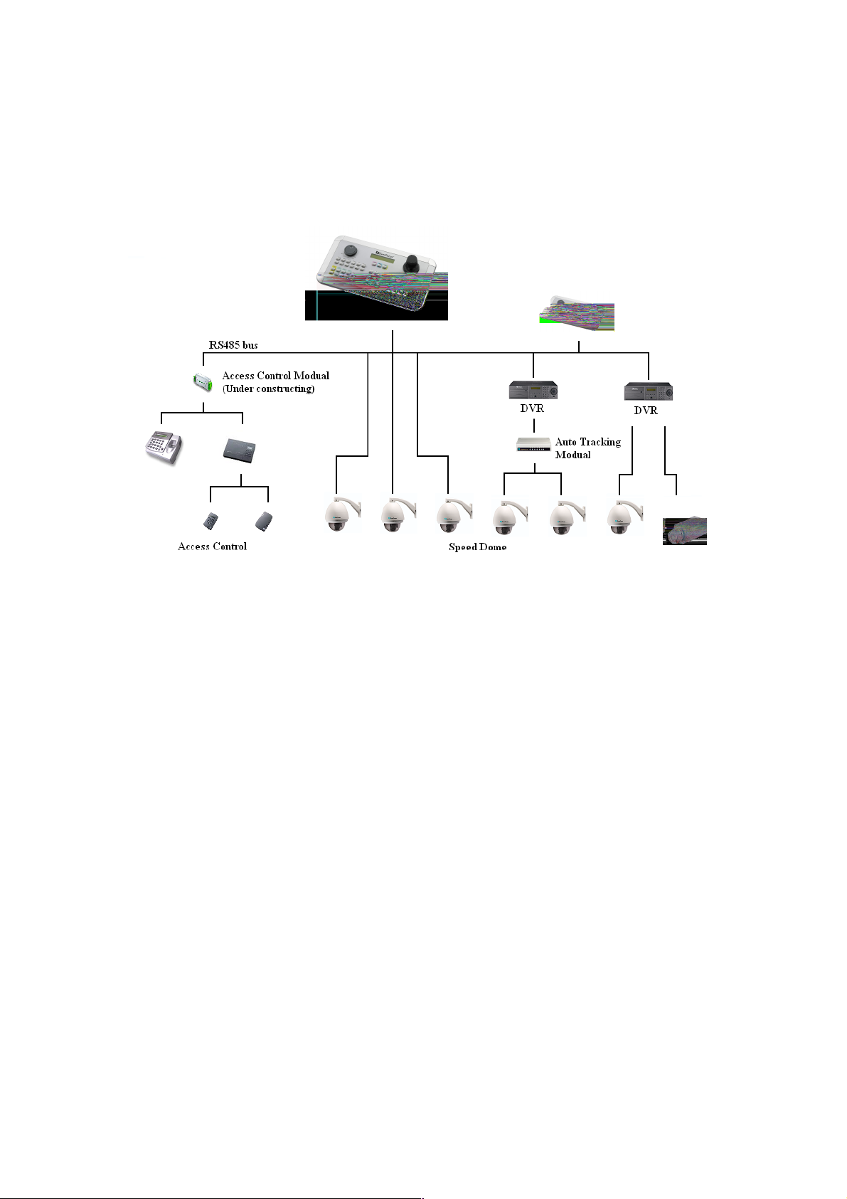
2.1. EKB500 KEYBOARD CONNECTION DIAGRAM
2.2. PACKING LIST
EKB500
Subkeyboards
Camera
Please check accessories in the packing before the installation.
1) EKB500 Multi-function controller keyboard X1
2) User’s manual in CD-ROM format/Hard Copy X1
3) Wiring Box for RS-485 connection X1
4) External Power adapter X1
5) RS-485 terminator X1
Page 6
6
2.3. Quick Installation and Operation Guide (Work with EPTZ1000)
EKB500 and EPTZ1000 (Speed dome) and can work together by using
factory default setting. You just need to connect cables by following
steps:
1. Connect the RS485 cable to EKB500 and EPTZ1000.
2. Connect a video cable from EPTZ1000 to a monitor.
3. Connect the power to EKB500 and EPTZ1000.
After the EPTZ1000 finishes the self-test mode, you can start to operate
the EPTZ1000 via the EKB500.
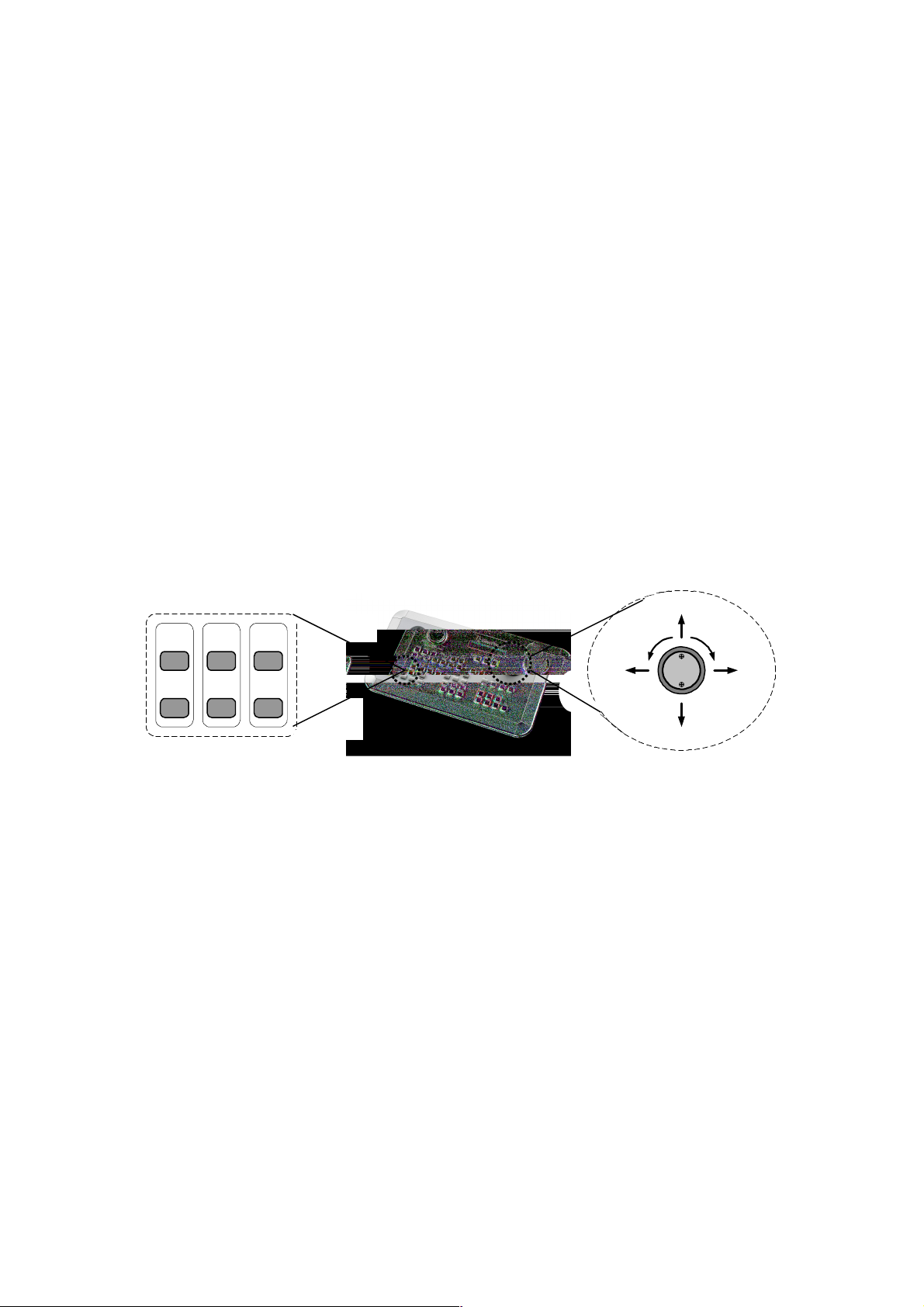
To operate the EPTZ1000:
IRIS+FocusF.Zoom
- N. Out
UP
In
LEFT RIGHT
Zoom INZoom OUT
DOWN
1. Shift the Joystick up/down or right/left to view from camera.
2. Turn the top of the Joystick to zoom in/out.
3. Press Zoom In/Out, Focus N. /F. and IRIS +/- function keys to
operate the EPTZ1000.
Page 7
7
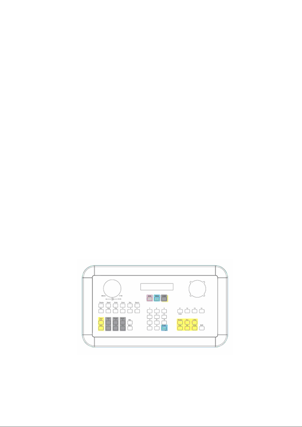
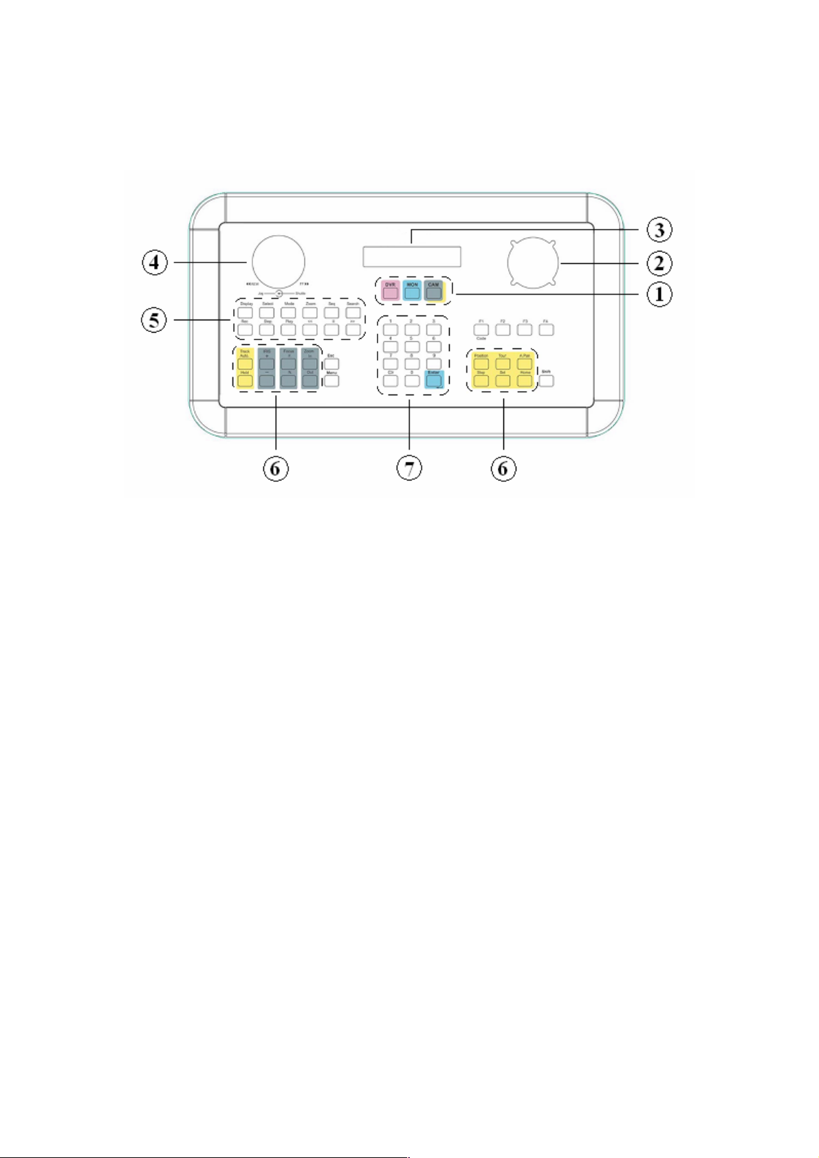
3. FEATURE
1. Main function keys
Main function keys allow you to switch the control of DVRs, monitors
and cameras easily.
2. Three-way Joystick
The 3-way Joystick is for controlling speed dome mainly. Shift it right/left
and up/down to view right/left and up/down subjects, and turn it
clockwise/counter-clockwise to zoom in/out.
3. LCD panel
The LCD panel shows operation information, and it has a capability to
display maximal 2 x 20 digits.
4. Jog and Shuttle
Jog and Shuttle dials allow you to control the play/reverse play back
speed of a DVR.
Page 8

8
5. DVR reserved keys
DVR reserved keys are for DVRs control mainly. You can operate a
DVR that is compatible with EKB500.
6. Speed Dome reserved keys
These keys are for Speed Dome control mainly.
7. Number keys
Numbers from 0~9, one Clr (clear) key and one Enter (enter) key.
Page 9

9
4. SETTING
After Keyboard powered on, firmware version will be displayed on the
panel, and the message will disappear after 3 seconds (Fig.1). After the
version display disappears, a display with 3 main categories that are CAM
(Camera), MON (Monitor) and DVR (Digital Video Recorder) will show on the
LCD panel (Fig.2).
Keyboard
Version 1.13
CAM:0001 MON:0001
____ [ CAM / MON / DVR ]
Fig. 1 Fig. 2
Some settings have many items (options). However, the LCD has only 2
lines on the panel. In order to display all items, a cursor “<“ at the end of the
second line indicates there are more options to display. Shift Joystick up and
down to display all items.
An item flashes when it is selected. You can press Enter to get into it, or
press Esc to return to previous setting list.
Press Shift + Menu to enter the main setup menu.
You will see 2 lines on the display, and the first line is flashing. You can
switch Joystick up/down to change the flashing line, and display more
subentries. Press Enter to get into the flashing line.
Page 10
10
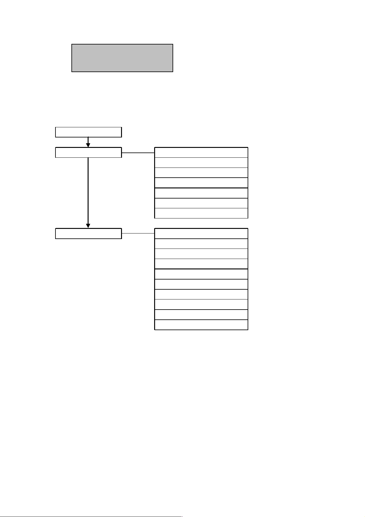
COM Port Setting
The structure of setup menu shows below:
Device Setting
COM Port Setting
Device Setting
Camera Setting
Monitor Setting
DVR Setting
Camera List & Delete
Monitor List & Delete
DVR List & Delete
Non-listed Device
Keyboard setting
Sub Keyboard Setting
MENU Password
Lock Password
Alarm Password
Buzzer ON/OFF
Joystick Calibration
Keypad Test
Jog & Shuttle Test
Load default setting
Firmware update
Page 11
11
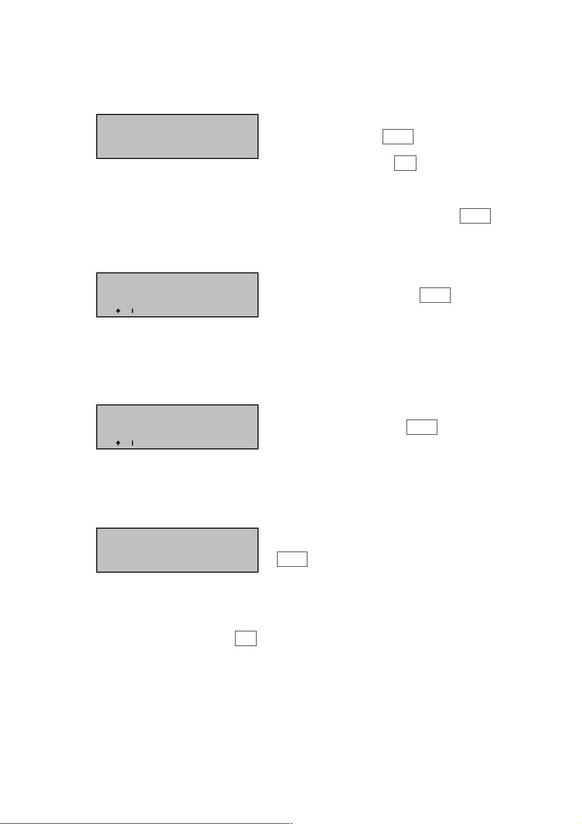
4.1. COM PORT SETTING
Select “COM Port Setting” (The line is
Port : _ ( 1 or 2 )
flashing), and press Enter to enter the
Input the port.
COM Port Setting, or Esc to go back
main setup menu. Key in the port you
want to set (1 or 2), and then press Enter.
Switch Joystick up/down to change the
BAUD : 9600 <
Baud Rate, and then press Enter. The
available Baud Rates are 1200, 2400,
4800 and 9600.
Switch Joystick up/down to change the
Protocol : EVF-1
protocol, and then press Enter. The
available protocols are EVF-1, EVF-2,
A-TYPE, PELCO-D and PELCO-P.
After finishing setting, you need to press
Port : 1 Changed
[ ENT ] to save
Enter to save the setting.
When the setting is saved, the display will go back to the COM Port Setting.
Enter another port to set, or Esc to quit the COM Port Setting.
Note: It’s important to select a correct Baud Rate and protocol for the device
connection, and please do not connect devices with different protocols/baud
rate to a COM port. For example: If you have 3 devices on Port 1 of the
Page 12

12
keyboard, all devices should be set with the same protocols and Baud Rate.
4.2. DEVICE SETTING
4.2.1. Camera Setting
Assign a name from 0~9999 to the
Camera Name : _ _ _ _
camera. The name can be different from
the RS485 address.
Select the RS485 port number to which
RS485 Connected to
Port : _ [ 1 or 2 ]
the camera connects.
RS485 Address:
Enter the RS485 address that the camera
_ _ _ _
is defined.
We define DVR number as “DVR”, and
Video Connected to
DVR : _ _ _ _ CH : _ _
the channel number to which the camera
is connected as “CH”.
Camera : 0001 changed
Press Enter to save the setting of the
[ ENT ] to save
camera.
Press Esc to quit the setting of the
camera without saving.
Page 13

13
4.2.2. Monitor Setting
Assign a name from 0~9999 to the
Monitor Name : _ _ _ _
monitor.
Assign the monitor to an output channel of
Video Connected to
DVR : _ _ _ _ Matrix : _ _
a DVR.
Press Enter to save the setting of the
Monitor : 0001 changed
monitor.
[ ENT ] to save
Press Esc to quit the setting of the
monitor without saving.
4.2.3. DVR Setting
Assign a name from 0~9999 to the DVR.
DVR Name : _ _ _ _
The name can be different from the RS485
address.
RS485 Connected to
Select the RS485 port number to which
Port : _ [ 1 or 2 ]
the DVR connects
RS485 Address:
Enter the RS485 address that the camera
_ _ _ _
is defined.
Page 14

14
DVR Type :
In this display, we define
Select the DVR brand and model name.
EDSR1600 <
The available models now are EDR410,
EDR810, EDR1620, EDR1640,
EDSR400H, EDSR400, EDSR600,
EDSR900 and EDSR1600.
DVR : 0000 set
Press Enter to save the setting of the
[ ENT ] to save
camera.
Press Esc to quit the setting of the
camera without saving.
4.2.4. Camera List & Delete
In the Camera List & Delete menu, you can check all available cameras. You
can also delete a camera from the list.
Total 005 Cameras
Show the camera amount. Press Enter to
[ ENT ] to view list
view camera list, or press Esc to quit.
Name
0012 2- 0014
RS485 DVR CH
0002
03 <
Name: The name of the camera.
RS485: The port and the address to which
the camera is connected. The
number before the “-“ is the port
number, the number after the
“-“ is the camera address
Page 15

15
number.
In this display, we define
DVR: The DVR to which the camera is
connected.
CH: The channel number to which the
camera is connected.
Switch Joystick up/down to change the cameras.
Del Camera0000
Press Enter for a camera you want to
[ ENT ] to confirm.
delete. Press Enter again to confirm.
4.2.5. Monitor List & Delete
In the Monitor List & Delete menu, you can check all available monitors. You
can also delete a monitor from the list.
Total 005 Monitors
Show the monitor amount. Press Enter to
[ ENT ] to view list
view monitor list, or press Esc to quit.
Name
DVR CH
0012 0014 0002 <
Name: The name of the monitor.
DVR: The DVR to which the monitor is
CH: The channel number to which the
monitor is connected.
connected.
Page 16

16
Switch Joystick up/down to change the Monitor.
Del Monitor0000
Press Enter for a Monitor you want to
[ ENT ] to confirm.
delete.
Press Enter again to confirm.
4.2.6. DVR List & Delete
In the DVR List & Delete menu, you can check all available DVRs. You can
also delete a DVR from the list.
Show the DVR amount. Press Enter to
Total 005 DVRs
[ ENT ] to view list
view DVR list, or press Esc to quit.
Name
RS485
In this display, we define:
0012 1- 0010
Name: The name of the DVR.
RS485: The port and the address to which the DVR is connected. The
number before the “-“ is the port number, the number after the “-“ is
the DVR address number.
Switch Joystick up/down to change the DVRs.
Del DVR : 0000
Press Enter for a DVR you want to delete.
[ ENT ] to confirm.
Press Enter again to confirm.
Page 17

17
4.2.7. Non-listed Device
In the Non-listed Device menu, you can set the keyboard only control the listed
device or not.
The message indicates the non-listed
Allow Operation w/o
device operation is allowed. Switch
Joystick up/down to disable it, and then
press Esc to quit.
The message indicates the non-listed
No Operation w/o
device operation is disabled. Switch
Joystick up/down to disable it, and then
press Esc to quit.
4.3. KEYBOARD SETTING
Keyboard setting provides you the configuration of this keyboard. You can
define keyboard type, set passwords, test keyboard and update firmware in the
setting.
4.3.1. Sub Keyboard Setting
This keyboard ID : 0
Key in the number of this keyboard.
( 0 – 7 , 0 for master )
MAX Subkeyboards :
Key in the total number of the keyboards
0 – 7 supported
on the RS485 bus.
Page 18

18
Note: Up to 8 keyboards can be connected, and each keyboard has to have
an exclusive ID to indicate each keyboard on the RS-485 bus. The master
keyboard ID has to value as 0 and the subkeyboards can be set from 1 to 7 as
its value.
4.3.2. MENU Password
You may lock the setup menu to protect unauthorized operation.
Input new Password :
Input a new menu password.
_ _ _ _ _ _ _ _
Repeat Password :
Repeat the new menu password.
_ _ _ _ _ _ _ _
Switch Joystick up/down to select
Protect setup menu
YES/NO, and then press Enter.
Select YES to enable a setup menu password, and a password-enabled
message will show up on the display.
Setup menu password
set and enabled.
Select NO to disable a setup menu password, and a password-disabled
Page 19

19
message will show up on the display.
Setup menu password
set but disabled.
4.3.3. Lock Password
You may lock the Keyboard to protect unauthorized operation.
Input new Password :
Input a new keyboard lock password.
_ _ _ _ _ _ _ _
Repeat Password :
Repeat the new keyboard lock
_ _ _ _ _ _ _ _
password.
Enable Lock password
Switch Joystick up/down to select
YES/NO, and then press Enter.
Select YES to enable a keyboard lock password, and a password-enabled
message will show up on the display.
Lock password
set and enabled.
Select NO to disable a keyboard lock password, and a password-disabled
message will show up on the display.
Page 20

20
Lock password
set but disabled.
4.3.4. Alarm Password
Alarm would not be turned off before the operator key-in a password to
terminate it. The keyboard is equipped with a buzzer for acoustic signals when
an alarm is enabled.
Input new Password :
Input a new alarm password.
_ _ _ _ _ _ _ _
Repeat Password :
Repeat the new alarm password.
_ _ _ _ _ _ _ _
Enable Alarm Passwd
Switch Joystick up/down to select
YES/NO, and then press Enter.
Select YES to enable an alarm password, and a password-enabled message
will show up on the display.
Alarm password
set and enabled.
Select NO to disable an alarm password, and a password-disabled message
will show up on the display.
Page 21

21
Alarm password
set but disabled.
4.3.5. Buzzer ON/OFF
Buzzer can be enabled or disabled by setting here. Switch Joystick to
change the buzzer status, and then press Enter to confirm.
Buzzer Enabled
Buzzer Disabled
4.3.6. Joystick Calibration
Joystick calibration helps users to test the functions of the Joystick.
Release Joystick, and then press Enter to
Release Joystick
and press [ ENT ]
test or press Esc to quit test.
The message shows up after pressing
Move joystick
to corners.
Enter.
X+000 Y+000 Z+000
X-000 Y- OK Z-000
There are 3 ways that are X, Y and Z to be checked, and each way has 2
Page 22

22
directions. We divide each direction into 16 scales. A direction will show OK if
the Joystick can reach the 16th scale.
Sway the Joystick up/down to check the X+/X- calibration.
Sway the Joystick right/left to check the Y+/Y- calibration.
Turn the Joystick clockwise/counterclockwise to check the Z+/Z- calibration.
4.3.7. Keypad Test
Under the Keypad testing stage, you may press any key on the keyboard and
the key name will display accordingly to the LCD.
[
_ _ _ _ _ _ _ _ _ _ ]
Pressed
[ Esc ] to exit
4.3.8. Jog & Shuttle Test
Shuttle : >>>> 5
Jog : 9934
Shuttle test:
Turn the Shuttle right/left and the sign “>>>>” / ”<<<<” shows up with a
number that indicates the scale of Shuttle. The scale number is zero before the
Shuttle is dialed. It increases from 0 to 7 when the Shuttle is dialed.
Jog test:
Dial the Jog clockwise, the number will increase.
Dial the Jog counter-clockwise, the number will decrease.
The number displays from 0000 ~ 9999.
Page 23

23
4.3.9. Load default setting
Load default setting
Press Enter to load default setting.
Press [ ENT ] to load.
In order to prevent a mistake, system
Input 123 to start
will ask you to enter 123, and then
_ _ _ [ ENT ]
press enter to start to load default.
The setting will go back to keyboard setting if the password is wrong.
The setting will go back to keyboard setting after a long buzzer if the password
is right, and every setting will be cleaned up.
4.3.10. Firmware update
In order to prevent a mistake, system
Input 123 to start
_ _ _ [ ENT ]
will ask you to enter 123, and then
press enter to start firmware update.
Page 24

24
5. KEYBOARD FUNCTIONS
There are three main functions that are in support of DVR, monitor and camera
of the keyboard.
5.1. DVR support
EKB500 can support DVRs, and control DVRs via DVR reserved keys.
Keyboard functions if the DVR has the according function. For instance, the
search key on the keyboard will not work if the DVR does not have the
function.
To add a DVR into the keyboard is necessary. Please check DVR setting on
page 13 to get more information.
To get controlled over a DVR:
DVR : 0001
[ CAM / MON / DVR ]
There are 2 ways to get controlled over a DVR.
1. Press the DVR key, and then the DVR line on the display will start to flash.
Press Enter after the DVR name is keyed in, and you can start to operate
the DVR.
2. Enter the DVR name, and then press DVR to get controlled over a DVR.
To operate a DVR:
The DVR reservation keys are available for operating a DVR. The following
table shows the main functions of a DVR operation. The buzzer will buzz three
Page 25

25
times if the protocol does not suppose the function after pressing the function
key.
DVR main function table:
Function Key
Enter setup menu Press MENU to enter the setup menu.
Full screen display Enter the channel number, and then press Enter
Zoom In/Out In the full screen mode, press Zoom to zoom
in/out.
Normal record Press Rec to record.
Normal playback Press Play to playback.
Search playback Press Search to search a time or a event for
playing back.
Fast Forward/Reverse
playback
Turn the Shuttle dial clockwise/counter-clockwise
during playback mode.
Pause playing back Press Pause to freeze a playing back image.
Stop playing back Press Stop to stop a playing back image.
Change the information
display mode
Change the screen
display mode
Press Display to change different information
display mode.
Press Mode to change different screen display
mode.
Sequence mode Press Seq to enable a sequence mode.
Call monitor setting Press Call to enter the call monitor setting.
Select mode Select a display on the screen. A start will show on
the selected display.
Copy a video file Press Copy to copy a video file.
Page 26

26
5.2. Monitor support
To add a monitor and a DVR into the keyboard devices before operating is
necessary. Please check monitor setting on page 13 to get more monitor
setting information.
To show camera on different monitor:
In order to do this, the camera and the monitor need to be connected to the
same DVR.
CAM : 0001 MON : 0001
[ CAM / MON / DVR ]
There are 2 ways to display a camera on a monitor:
1. Press the MON key, and then the MON line on the display will start to flash.
Press Enter after the monitor name is keyed in, and then DVR will display a
selected video on the assigned monitor.
2. Enter the DVR name, and then press MON to command a matrix. Example:
Press 0 0 1 2 MON, the current camera’s image will show on
the monitor 12.
5.3. Camera (Speed dome) support
EKB500 can support speed domes (or cameras), and control speed domes via
DVR reserved keys. Keyboard functions if the camera has the according
function. For instance, the search key on the keyboard will not work if the
camera does not have the function.
Page 27

27
To add a speed dome into the keyboard device is necessary. Please check
camera setting on page 12 to get more information.
To get controlled over a camera (speed dome):
CAM : 0001 MON : 0001
[ CAM / MON / DVR ]
There are 2 ways to get controlled over a speed dome camera.
1. Press the CAM key, and then the CAM line on the display will start to flash.
Press Enter after the camera name is keyed in, and you can start to operate
the speed dome camera.
2. Enter the camera name, and then press CAM to get controlled over a speed
dome camera.
To operate a camera (speed dome):
You can operate the selected speed dome camera by using camera
reservation keys of EKB500. The functions that can be operated by the
EKB500 depend on different protocols. The buzzer will buzz three times if the
protocol does not suppose the function after pressing the function key.
Camera main function table:
Function Key
Manual up/down/right/left Switch the Joystick up/down/right/left.
Zoom In/Out Press Zoom In / Zoom Out.
Focus Far/Near Press Focus F. / Focus N..
Page 28

28
IRIS +/- Press IRIS + / IRIS -.
Go to a position Position number + Position / Position +
position number, and then press Enter
Save a position Press Shift + Position to save a position.
Set position parameter Press Set + Position to set position parameter.
Delete a position Press Clr + Position to delete a position.
Tour mode 1 (One-way) Press Tour to run a one-way tour.
Tour mode 2 (To-and-fro) Press Shift + Tour to run a to-and-for tour.
Set a tour Press Set + Tour to set a tour.
Start auto pan Press A.Pan to start a two-point auto pan.
360 auto pan mode Press Shift + A.Pan to start a 360 auto pan.
Set auto pan Press Set+ A.Pan to set an auto pan.
Go back to home position Press Home to go back to the home position.
Set auto go back home Press Set + Home to set auto go back home
position.
Link an alarm to a position
Press F1 to link an alarm to a position or tour.
or tour
Delete an alarm link to a
position or tour
Press Clr + F1 to delete a link of an alarm to a
position or tour.
Page 29

29
6. DEVICE CONTROL OPERATION GUIDE
The device connection depends on the users’ application. Users can
check the device’s manual to set up and operate the keyboard. Two examples
here provide you the guide of basic functions to operate.
6.1. To operate a speed dome (EPTZ1000)
In order to operate a speed dome, to get controlled over the speed dome
is necessary. There are 2 ways to get controlled over a speed dome camera,
which are:
1. Press the CAM key, and then the CAM line on the display will start to
flash. Press Enter after the camera name is keyed in, and you can start
to operate the speed dome camera.
2. Enter the camera name, and then press CAM to get controlled over a
speed dome camera.
6.1.1. Manual Control Mode
Manual control: Shift Joystick Up/Down/Left/Right, and turn it
Clockwise/Counterclockwise to control speed dome.
Use the control keys which are Zoom, Focus and IRIS function keys on
the keyboard to zoom in/out, focus N (near)/F (Far), or IRIS +/-.
HOME Mode: The camera view will go back to the home position when
there is no keyboard operation in a specific time. The home position and
the specific time can be set by pressing Set + Home.
Page 30

30
Back to home if no
Enter the specific time to go back home
action for ___Minute
position, and then press Enter.
Switch the Joystick to move the view to
Move to home position
the home position, and then press Enter
[ENT] to confirm
to confirm the home position.
Switch the Joystick to enable or disable
Auto Back Enabled
the auto back home function, and then
press Enter to confirm.
6.1.2. Auto Pan Mode
Two point auto pan: Press A.Pan to enter the auto pan mode, and
then the system will ask you to enter the auto pan speed (1~239). Press
Enter to start auto pan.
Speed:___[1-239]
[ENT] to start.
In order to set the two points, press Set
Position A
+ A.Pan, and then enter the dwell time
Dwell:___[1-239]
(1~239 seconds) of position A.
Move to Position B
Move to the position B of auto pan, and
[ENT] to confirm
then press Enter.
Page 31

31
Position B
Enter the dwell time of position B, and
Dwell:___[1-239]
then press Enter to finish setting.
360° auto pan: Press Shift + A.Pan to enter the 360° auto pan. The
camera will turn 360° automatically, but not tilt.
6.1.3. Position Setting
Focus on a preset position: Press the number key, and then press
Position to focus on the number of preset position; or you can press
Position, then enter the preset position number, and then press Enter
to focus on the number of preset position.
Camera:0001 go to
Position:___[1-192]
Preset a position: Shift the Joystick to the position you would like to
preset, and then press Shift + Position. The system will ask you to
enter the preset position number (1~239), and then press Enter to save
the position. There are up to 192 positions can be preset.
Camera:0001 Save to
Position:___[1-192]
Set the parameter of a preset position: Press Set + Position to set
the parameter of a preset position. You can set the going-to speed
(1~239), dwell time (1~239 seconds), and the title of the position.
Page 32

32
Set Camera:0001
Set Position:001
Position:___[1-192]
Speed:___[1-239]
Set Position:001
Dwell:___[1-239]
Shift the joystick Right/Left to change bits, and shift the Joystick
Up/Down to change the alphanumeric characteristic. The available
alphanumeric characteristics are 0~9, A~Z, &, ?, !, :, ‘, ., ,, /, -, and a
space.
Title for position
____________________
V
___________________
Delete a preset position: Press Clr + Position to delete a preset
position. The system will ask you to enter the position number that you
would like to delete, and then press Enter.
Camera:0001
Del Position:___
6.1.4. Tour Mode
In the tour mode, you can set a tour for viewing. There are 16 tours can be
set, and 16 preset positions in a tour.
One-way tour Mode: Press Tour to enter the tour mode. The system
will ask you to enter the tour number you would like to run, and starts
Page 33

33
the tour after pressing Enter. To preset a tour before running it is
necessary.
Camera:0001
Run Tour:__[1-16]
Preset a one-way tour: Press Set + Tour to preset an one-way tour.
The system will ask you to enter preset position numbers (The positions
need to be preset). After finish entering all positions, press Stop to quit,
and then press Enter to save the tour.
Set Camera:0001
Add Position#01:___
Tour:__[1-16]
[ENT / STOP]
Tour:001 Pos#01:001<
[ENT] to save
To-and-fro tour mode: Press Shift + Tour to run a to-and-fro tour. The
system will ask you to enter the tour number you would like to run, and
starts the tour after pressing Enter. To preset a tour before running it is
necessary.
Note: The difference between the One-way tour mode and To-and-fro tour
mode is that the return modes are different. For example: There is a tour with 3
preset positions 1, 2 and 3. The camera runs 123123 in the One-way
tour mode, and 12321 in the To-and-fro tour mode.
Page 34

34
6.1.5. Alarm to Position/Tour Link
EPTZ1000 have 4 alarm inputs that can be set to link to a position or a tour
when an alarm is triggered.
Set an alarm link:
Press F1 to set an alarm link. Enter the alarm number, and then press
Enter. Switch the Joystick up/down to select a position or a tour, enter a
position or tour number, and then press Enter to confirm the setting.
Link Alarm:_ [1-4] to
Link Alarm:_ [1-4] to
Delete an alarm link:
Press Clr + F1 to delete a link of alarm to position/tour.
Del AlarmLink:_[1-4]
[ENT] to confirm
6.2. To operate an DVR (EDSR900/1600)
In order to operate a DVR, to get controlled over the DVR is necessary.
There are 2 ways to get controlled over a DVR, which are:
1. Press the DVR key, and then the DVR line on the display will start to
flash. Press Enter after the DVR name is keyed in, and you can start to
operate the DVR.
2. Enter the DVR name, and then press DVR to get controlled over a
Page 35

35
DVR.
6.2.1. Main setup menu
Press MENU to enter the main setup menu. In the main menu, dial the
Shuttle to select an item or a value, and press Enter to enter a subentry or go
to next item. There are 17 items in the main menu, which are CLOCL,
DAYLIGHT SAVING, TIMER, SEQUENCE, TITLE, COVERT, ALARM,
MOTION, RECORD, NETWORK, CONTROL, BUZZER, ARCHIVE, MATRIX,
DISK, PTZ and SYSTEM setting menus.
6.2.2. Recording
Instant recording: Press Rec to start normal recording.
Schedule recording: The schedule recording needs to be set up and
enabled in the TIMER SETTING MENU.
Alarm recording: The alarm recording needs to be set up and enable
in the ALARM SETTING MENU.
Motion recording: The motion recording needs to be set up and
enabled in the MOTION SETTING MENU.
6.2.3. Play back
Normal playback: Press the Play key to start playing back the stored
image form last segment.
Fast Forward/Reverse playback: During playing back, turn the
Page 36

36
Shuttle dial clockwise to start fast playback; and turn the Shuttle dial
counter-clockwise to start fast reverse playback. The available speeds
are 2X, 4X, 8X, 16X, 32X and 600X for both forward and reverse.
Slow Forward/Reverse playback: During playing back, press Pause
to freeze the playing back picture. Turn the Shuttle dial clockwise to
start fast playback; and turn the Shuttle dial counter-clockwise to start
fast reverse playback. The available speeds are 1/2X, 1/4X, 1/8X,
1/16X and 1/32X for both forward and reverse.
Field advance Forward/Reverse: During the pause mode, turn the
Jog dial clockwise or counter-clockwise to get still images field by field.
Search playback: Press Search to enter search playback mode.
There are 3 search modes available that are search by segment list,
search alarm list, and search by data time.
6.2.4. Copy
The copy function is not available during record mode. To insert a
compatible CF card before copy is necessary.
Still image copy: In the pause mode, dial Jog to select a wanted image.
Press Copy to copy the still image.
Copy to a movie file: In the playback mode, press Copy to enter a
copy OSD. Follow the messages on the OSD to complete the movie file
copy.
Page 37

37
6.2.5. Monitor views / operation
Main monitor: In the main monitor, press Mode to switch the different
multi-screen mode, press Display to switch the OSD displays, or press
channel number + Enter to display in a full screen.
Call / Matrix monitor: Press Call to set up the call/matrix monitor. The
sequence for a call/matrix monitor is set up here as well.
There are some other functions of a DVR, and only main functions listed
here. To check a DVR manual for more detailed functions.
Page 38

38
EverFocus Electronics Corp.
Head Office:
China Office:
12F, No.79 Sec. 1 Shin-Tai Wu Road,
Hsi-Chih, Taipei, Taiwan
TEL: +886-2-26982334
FAX: +886-2-26982380
www.everfocus.com.tw
USA Office:
1801 Highland Ave. Unit A
Duarte, CA 91010, U.S.A.
TEL: +1-626-844-8888
FAX: +1-626-844-8838
www.everfocus.com
European Office:
Albert-Einstein-Strasse 1
D-46446 Emmerich, Germany
TEL: 49-2822-9394-0
FAX: 49-2822939495
Room 609, Technology Trade Building,
Shandgdi Information Industry Base,
Haidian District, Beijing,China
TEL: +86-10-62971096
FAX: +86-10-62971432
www.everfocus.com.cn
Japan Office:
1809 WBG MARIBU East 18F,
2-6 Nakase.Mihama-ku.
Chiba city 261-7118, Japan
TEL : +81-43-212-8188
FAX : +81-43-297-0081
www.everfocus.com
www.everfocus.de
PN: MKB3G00100
 Loading...