

Page 1
IP 99 Series
EVS110 1CH Video Server
EIP220 Network Camera
User’s Manual
Copyright © EverFocus Electronics Corp,
Version Release: Dec. 2008
Page 2

IP99 series
Product Name: IP99 EverFocus Network Cameras
Model Number(s): EVS110, EIP220
FCC Notice "Declaration of Conformity Information"
This equipment has been tested and found to comply with the limits for a Class
A digital device, pursuant to part 15 of the FCC Rules. These limits are designed
to provide reasonable protection against harmful interference in a residential
Installation. This equipment generates, uses and can radiate radio frequency energy
and, if not installed and used in accordance with the instructions, may cause harmful
interference to radio communications. However, there is no guarantee that
interference will not occur in a particular installation. If this equipment does cause
harmful interference to radio or television reception, which can be determined by
turning the equipment off and on, the user is encouraged to try to correct the
interference by one or more of the following measures:
- Reorient or relocate the receiving antenna.
- Increase the separation between the equipment and receiver.
- Connect the equipment into an outlet on a circuit different from that to which the
receiver is connected.
- Consult the dealer or an experienced radio/TV technician for help.
Warning: Changes or modifications made to this equipment, not expressly approved
by EverFocus or parties authorized by EverFocus could void the user's authority to
operate the equipment.
This device complies with part 15 of the FCC Rules. Operation is subject to the
following two conditions:
(1) This device may not cause harmful interference, and
(2) This device must accept any interference received, including interference that
may cause undesired operation.
EverFocus Electronics Corp.
12F, No. 79, Sec. 1, Shin-Tai Wu Rd., His-Chi,
Taipei Hsien, Taiwan, R.O.C.
IP99 complies with FCC.
1
Page 3

IP99 series
About this document
All the safety and operating instructions should be read and followed before the
unit is operated. This manual should be retained for future reference. The
information in this manual was current when published. The manufacturer reserves
the right to revise and improve its products. All specifications are therefore subject
to change without notice.
Safety Notice
-These limits are designed to provide reasonable protection. This equipment
generates, uses and can radiated radio frequency energy and, if not installed and
used in accordance with the instructions, may cause harmful interference to radio
communications. However, there is no guarantee that interference will not occur in
a particular installation. If this equipment does cause harmful interference to radio
or television reception, which can be determined by turning the equipment off and
on, the user is encouraged to try to correct the interference by one or more of the
following measures: -Reorient or relocate the receiving antenna.
-Increase these separations between the equipment and receiver.
-Connect the equipment into an outlet on a circuit different from that to which the
receiver is connected.
-Consult the dealer or an experienced radio/TV technician for help.
The changes or modifications not expressly approved by the party responsible for
compliance could void the user's authority to operate the equipment.
To reduce risk of fire or electric shock, do not expose this appliance to rain or
moisture.
Do not attempt to disassemble the appliance. To prevent electric shock, do
not remove screws or covers. There are no user-serviceable parts inside.
Contact qualified service personnel for maintenance. Handle the appliance with
care. Do not strike or shake, as this may damage the appliance.
Do not use strong or abrasive detergents when cleaning the appliance body.
Use a dry cloth to clean the appliance when it is dirty. When the dirt is hard to
remove, use a mild detergent and wipe gently.
Do not operate the appliance beyond its specified temperature, humidity or
2
Page 4

IP99 series
power source ratings. Do not use the appliance in an extreme environment where
high temperature or high humidity exists. Use the appliance at temperature within
-10℃ ~ 50℃ / 14 ~ 1℉ 22 and a humidity below 90%. The input power source ℉
for this appliance is 12VDC.
Use only the recommended power supplies. Power supplies must comply
with the requirement of the latest version of IEC60950-1. Substitutions may
damage the unit or cause a fire or shock hazard.
Electrostatic-sensitive device. Use proper CMOS/MOSFET handing
precautions to avoid electrostatic discharge.
Installation should be performed by qualified service personnel only in
accordance with the National Electrical Code or applicable local codes.
Terms and Trademark
Ethernet, Internet Explorer, Linux, Microsoft, Windows, WWW are registered
trademarks of the respective holders. Other product names appearing in this User's
Guide may be trademarks or registered trademarks of their respective holders.
Java™ and all Java-related logos and trademarks are trademarks or registered
trademarks of Sun Microsystems, Inc. in the United States and other countries.
Support
If the unit ever needs repair service, the customer should contact the nearest
EverFocus Electronics Corp. Service Center for return authorization and shipping
instruction.
Minimum Computer Requirements:
-CPU: PC Pentium IV (2.0 GHz or higher) / AMD Athlon (or higher)
-VGA card: 32 MB min, 16,7 million colours, with DirectX9.0c support
-Memory: 512 MB RAM min., 1 GB HD space or above
Additional HD space depends on required local storage of video files,
-Ethernet: 100 Mbps
-Operating System: Windows XP, service pack 2 or higher, Windows 2000, Windows
Vista (turn off User Account Control)
-Software: DirectX9,0c, Microsoft IE 4.X or higher
Note: Please connect to Microsoft’s Web Site for downloading:
3
Page 5

IP99 series
For example: (This web site may change without notices.)
http://www.microsoft.com/downloads
4
Page 6

IP99 series
TABLE OF CONTENTS
1. STARTING THE CAMERA OR VIDEO SERVER ............................................. 7
1.1 INSTALL IP99 SEARCHER IN PC ............................................................................. 7
1.2 ASSIGN NEW IP ADDRESS (OPTIONAL) .................................................................. 7
1.3 ACCESSING THE CAMERA ...................................................................................... 8
1.4 RESET AND FACTORY DEFAULT ............................................................................. 9
2. IP99 SYSTEM OPERATION ................................................................................. 9
2.1 ADD MORE VIDEOS .............................................................................................. 10
2.2 CHANGE VIDEO RESOURCE .................................................................................. 10
2.3. EDIT AND CHANGE DISPLAY LAYOU T ................................................................. 11
2.3.1 Edit layout ................................................................................................... 11
2.3.2 Save layout setting ...................................................................................... 11
2.4 ZOOM IN/ZOOM OUT ............................................................................................ 12
2.4.1 Integer zoom in/zoom out ........................................................................... 12
2.3.2 Single display zoom in/zoom out ................................................................ 12
2.4 OPERATING BUTTONS .......................................................................................... 12
2.4.1 Record ......................................................................................................... 12
2.4.2 Stop recording ............................................................................................. 13
2.4.3 Snapshot ...................................................................................................... 13
2.4.4 Playback ...................................................................................................... 13
2.4.5 PTZ control panel (for Video Server only) ................................................. 14
2.4.7 System setting ............................................................................................. 15
2.4.8 Right-click functions ................................................................................... 15
3. SYSTEM SETTING .............................................................................................. 17
STATUS INFORMATION ......................................................................................... 17
3.1
3.2
VIDEO/AUDIO SETTING ........................................................................................ 18
3.3 DEVICE SETTING.................................................................................................. 19
3.4 ALARM EVENT .................................................................................................... 20
3.5 NETWORKING ...................................................................................................... 22
3.6 WIRELESS LAN .................................................................................................. 23
3.7 PPPOE SETTING .................................................................................................. 23
3.8 DDNS SETTING ................................................................................................... 24
3.9 SMTP SETTING ................................................................................................... 24
3.10 FTP SETTING ..................................................................................................... 25
3.11 DATE & TIME SETTING ...................................................................................... 26
5
Page 7

IP99 series
3.12 PTZ SETTING ..................................................................................................... 26
3.13 ADMINISTRATOR ............................................................................................... 27
3.14 CHANGE PASSWORD .......................................................................................... 28
3.15 SPECIAL SETTING ............................................................................................... 28
3.16 MAINTENANCE .................................................................................................. 29
4. FREQUENTLY ASKED QUESTIONS ............................................................... 30
4.1 I HAVE PROBLEM RECORDING AND PLAYBACK ON WINDOWS VISTA. ................... 30
6
Page 8
IP99 series
1. Starting the camera or video server
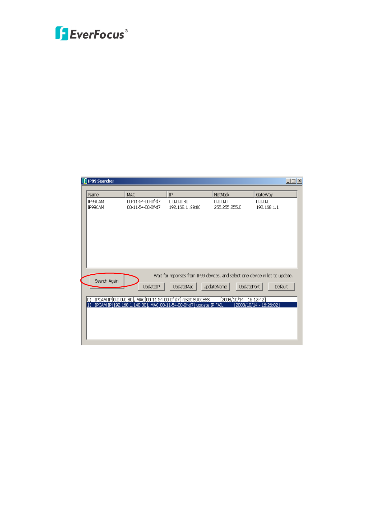
1.1 Install IP99 searcher in PC
Though you can simply enter 192.168.1.99 in IP address bar to access camera
when you connect to only one IP99 device.( Default IP address is: 192.168.1.99
Port is: 80). However, it is recommended that you use IP search to manage IP camera
and encoder. Please insert CD to install IP99 searcher tool. After finishing installation,
click “IP searcher” icon to find IP99 encoders and cameras. Click “Search Again” to
refresh list as shown in diagram 1.1
Diagram 1.1 Search IP device
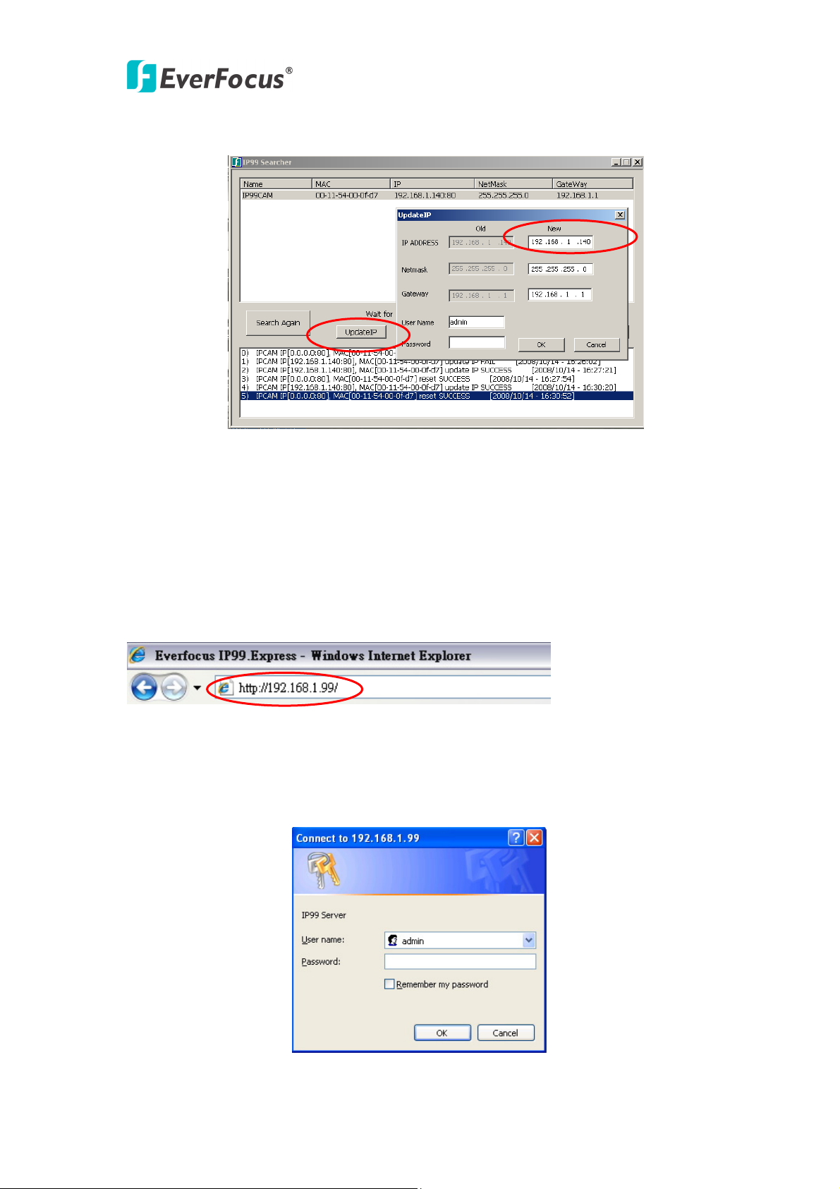
1.2 Assign New IP address (optional)
The Default IP address is 192.168.1.99. You can change IP address through IP
searcher. You don’t need to change IP address if you connect only one IP device. If
you are connecting to multiplies of IP99 devices, please assign different IP address for
different cameras For example, if you have 2 IP cameras, click “UpdateIP” to show
old and new IP address. Then change to the IP address you want. Type default user
name: admin, password: 11111111 then click “OK”. See diagram 1.2
Otherwise, you can set camera as DHCP. Please refer to 3.6 network setting.
7
Page 9
IP99 series
Note: Please consult your network administrator for avoiding IP address conflict
Diagram 1.2 Assign new IP address
1.3 Accessing the camera
Double click selected camera in IP99 searcher or Enter IP address in IP address bar, as
shown in diagram 1.3:
Diagram 1.3 enter IP address
Enter IP address and click Enter to confirm, login window will pop up as shown in
diagram 1.4:
Diagram 1.4 login window
8
Page 10
IP99 series
In login window, enter user name and password, (default user name is admin,
password is 11111111). Click“Confirm"button to enter web window, as shown in
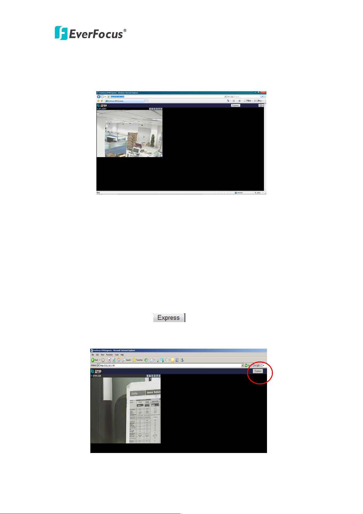
diagram 1.5:
Diagram 1.5 Camera Web page
1.4 Reset and Factory Default
You can physically push” RST” button on IP99 camera or click “Default” on IP
searcher to back to factory default.
2. IP99 system operation
After entering to web window, a button shows on top right corner, click
this button enter to an easy to operate window, as shown in diagram 2.1:
Diagram 2.1 Express operation page
9
Page 11

IP99 series
2.1 Add more videos
If you wish to add one video display in the same web page, click “Add New” button,
as shown in diagram 2.2:
Diagram 2.2 Add video display
2.2 Change video resource
You can change video resource and simultaneously view multiplies cameras
and encoders at same time.
Right click mouse on display center point and go to “Change Resource”.
Then you would see the login page. Enter IP address, user name, password for the
camera you want to add. Default username is admin, NO password. Now you can add
more cameras. See Diagram 2.3
Diagram 2.3 Change video resource
10
Page 12

IP99 series
2.3. Edit and Change Display Layout
2.3.1 Edit layout
If you wish to add more video displays, please click , then interface
changes to ,you can
freely set the layout of video display in this window.
Enter the number of channels you want for each row. Use comma to separate them.
And click to make the actual layout change. For example,”5,3,0”,
“shows the following layout. As shown in diagram 2.4:
Diagram 2.4 Display re-layout
After editing layout, click “Save” button to save settings.
Note: When you open IP browser again, click button, IE interface will
return to the layout order that you lastly saved.
2.3.2 Save layout setting
You can save in preset layouts from layout0~layout10 for using it in the future.
Total 10 preset layouts are supported by IP99 express. To save and load the wanted
layout, click icon at the left top corner, a layout list will pop up; click the
needed layout to change. See diagram 2.5.
11
Page 13

IP99 series
2.4 Zoom in/zoom out
Diagram 2.5 Layout selection
2.4.1 Integer zoom in/zoom out
Click buttons at top right side of the page to zoom in or zoom out the entire
screen.
2.3.2 Single display zoom in/zoom out
To zoom in/zoom out single channel screen, direct the mouse to at top of
that channel display, and click on , slide the tilt wheel of mouse to zoom in or
zoom out video images.
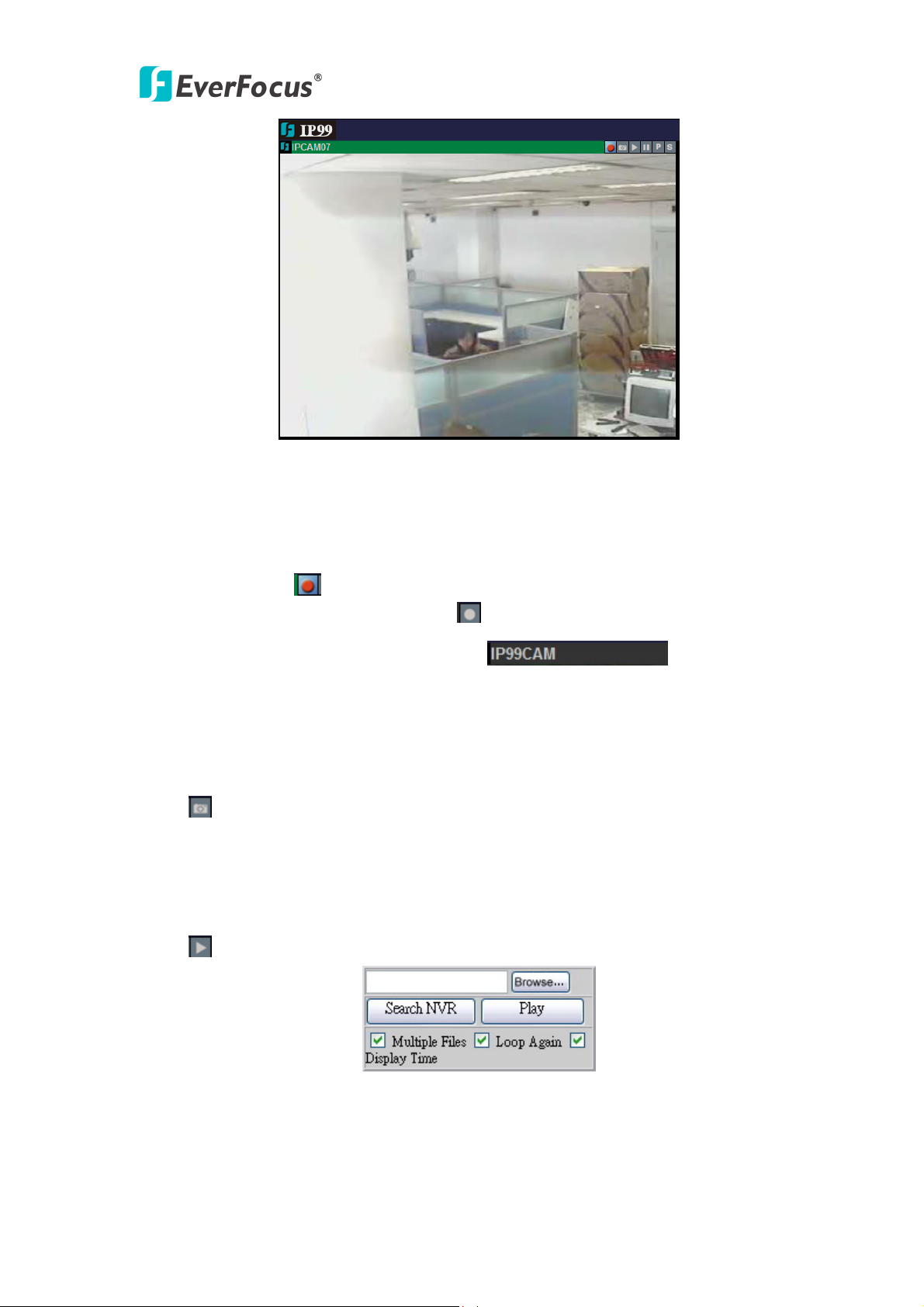
2.4 Operating buttons
There are 6 operating buttons at top right corner of every camera display
, their functions are described as follows:
2.4.1 Record
Method 1: Click on button located at top right corner of the image. Record
function is activated, button changes to .
Method 2: Double click on , this area will turn to green color,
and the device starts to record immediately, as shown in diagram 2.6:
12
Page 14
IP99 series
Diagram 2.6 Record
2.4.2 Stop recording
Method 1: Click on
button located at top right corner of the image, it will stop
recording immediately, button changes to .
Method 2:Double click on the green area of , it returns to
original color meaning that recording is stopped.
2.4.3 Snapshot
Click button to snapshot the image,default file path for the snapshot is:
C:\image99\...
2.4.4 Playback
Click button,playback window pops up as shown in diagram 2.7:
Diagram 2.7 Playback
Click “Browse"button to search file to be played. Default file path for the image
recorded is:C:\rec99\06-05\IP99CAM.
13
Page 15

IP99 series
Click “Search NVR"button to search the NVR device used for archiving recording
files. If you do not have NVR device, please ignore this selection.
Open the file to be played, click “Play"to play recorded video.
¾ Click fast forward button , to adjust playback speed.
¾ Click fast reverse button , to adjust reverse speed.
¾ Click pause button , to pause the video.
¾ Click play button , to stop playback, returning to normal page.
Note: If you have problem when use windows vista, please refer to 4.Frequesntly ask
question.
2.4.5 PTZ control panel (for Video Server only)
PTZ function is available when you connect PTZ to IP99 video server or use IP99
PTZ. IP99 supports Pelco-D, Pelco-P protocol PTZ control
Click button, a PTZ control panel pops up, as shown in diagram 2.8:
Diagram 2.8 PTZ control panel
1)Zoom:Click“T"button to zoom in. Click“W"button to zoom out.
Right click the mouse at the top right corner of video display to zoom in.
Right click the mouse at the bottom right corner of video display to zoom out.
2)Focus: Click“F"or“N"button to control the focus.
Right click the mouse at the left side of video display to adjust the focus.
3)Iris: Click“O"or“C"button to control iris.
4)Set preset position:Direct the camera to preset position, select preset number, click
“S"button to save preset position setting.
5)Go to preset position: Select preset position and click “GO” button.
6)Delete preset position:select the preset position number and click “C" button to
delete it.
Note 1:Left click the mouse around the video display to freely control the PTZ.
14
Page 16

IP99 series
Note 2:PTZ control can also be preformed by using PC’s keyboard, please refer to
section 5 of 2.4.7 for more details.
Note3: PTZ control is functioning only if PTZ Function is set On in PTZ Setting,
please refer to section 3.12.
2.4.6 On-Screen PTZ Control (for Video Server only)
On Screen PTZ function is available when you connect PTZ to IP99 video server or
use IP99 PTZ.
a) Left click mouse in the view to move PTZ to the clicked direction
b) Zoom in/out: Right click mouse at top right corner to zoom in and right click
mouse in lower right corner to zoom out
Zoom in Zoom out Focus
c) Focus: Right click mouse at left top and bottom corner to adjust focus.
2.4.7 System setting
Click button to make system setting. Plaese refer to Chapter 3 for more details.
2.4.8 Right-click functions
Right click the mouse at the center part of screen, a function window pops up as
shown in diagram 2.9:
Diagram 2.9 right-click functions
1) Display size: Click “Display size"option to set display size.
15
Page 17

IP99 series
Diagram 2.10 Display size
2)Change source: Click“Change source"to fill out information for the IP camera to
be controlled, as shown in diagram 2.11:
Diagram 2.11 Change source
First row: Camera name
Second row: IP address of camera to be connected
Third row: User name
Fourth row: Login password
When you finish filling out, click on“Change"button to enter video display with
setting changed. If you do not need to change those settings, please click “Abort” to
exit from this page.
3)Alarm setting:Click“Alarm setting"to enter alarm setting as shown in diagram
2.12 window:
Diagram 2.12 Alarm setting
16
Page 18

IP99 series
4)Sound ON:used to enable/disable sound transmission.
5)PTZ(for Video Server only):Click “PTZ"option which allows you to check
keyboard keys of PC used to control speed dome, as shown in diagram 2.13:
Diagram 2.13 PTZ contraol keys and functions
6)File .av to AVI:Click“File .av to AVI"option, select .av file to be converted and
click “Confirm” to save it as AVI format.
Diagram 2.14 File .av to AVI confirmation dialogue box
Note:AVI is the most widely used playback format.
3. System setting
3.1 Status information
Click button to enter setup menu, the screen shows camera’s current status, as
shown in diagram 3.1:
17
Page 19

IP99 series
Diagram 3.1 status information
3.2 Video/audio setting
Select 2. Video & Audio from the drop-down menu at top right corner, as shown in
diagram 3.2:
Diagram 3.2 Video & Audio settings
Enable settings for video stream, snapshot, OSD, Record and Audio.
1)CBR setting: Set CBR enabled or disabled, default value is Disable.
Note: CBR is fixed ratio.
18
Page 20

IP99 series
2)Resolution: Set record resolution
D1: 720x480 (NTSC) / 720x576 (PAL)
Half D1: 720x240 (NTSC) / 720x288 (PAL)
CIF: 352x240 (NTSC) / 352x288 (PAL)
QCIF: 176x120 (NTSC) / 176x144 (PAL)
3)Limit frame rate to: Set frame rate according o resolution.
4)OSD setting: Set OSD text and font size.
5)Record: Set REC File path, REC file Duration Time and REC Disk Overwrite at.
“REC Disk Overwrite at” means that when HDD remaining storage is less than the
value you set, IP99 will deleted previous recording data, in order to keep the newest
information.
6)Audio: Set audio volume, enable IP cam audio and enable PC audio.
Note:When settings are completed, click “Save"button to save settings.
3.3 Device setting
User can adjust video screen according to status of real environment.
Diagram 3.3(a) Device setting
Diagram 3.3(a)shows all functions that all IP99 series have. User can set Brightness,
Contrast and Color.
Brightness: Adjust image’s brightness level.
Contrast: Adjust contrast to make image clearer.
Color: Adjust color of the screen.
19
Page 21

IP99 series
Diagram 3.3(b)Device setting
Diagram 3.3(b)shows the functions of IP camera, it is for IP camera NOT for Video
Server. It has some additional functions compared to other cameras, as shown in
diagram 3.3 (c):
Diagram 3.3(c)Extension functions of device setting
Mirror: Enable or Disable Mirror function by selecting ON/OFF.
Shutter Speed: Control exposure time by changing shutter speed value. If lighting
source is sufficient enough, the exposure time required is less. By contrast, if lighting
source is insufficient, the exposure time required is more.
Set Shutter Speed to Auto if a manual iris lens is used. When a DD auto iris lens is
connected, set Shutter Speed to 1/60 and can adjust IRIS Level Control remotely.
BLC: Enable or Disable Back Light Compensation function by selecting ON/OFF.
AGC Max: Maximum value of Auto Gain Control. Set lower AGC Max in order to
prevent recording noisy video of huge data size at night.
Note: Funtions shown in Diagram 3.3(c)are only available for IP camera.
3.4 Alarm Event
Select motion detection area, click “Edit Region” then keep left clicking to drag the
area to be detected on the screen. Click “End Edit” to save change. To delete the
20
Page 22

IP99 series
selected area, click “Remove region”. Please refer to diagram 3.4:
Diagram 3.4 Alarm event
1)Motion detection event: No event, send JPEG file by e-mail or upload to FTP.
Note: When sending JPEG by e-mail or upload to FTP, file will be sent to the
assigned e-mail adress.
2)Alarm I/O setting: Set Alarm Input/Output setting and status, as shown in diagram
3.5: Select Alarm input level high, low or no alarm for each AI alarm inputs. Different
alarm actions: send JPEG file by e-mail, load to FTP or no action can be selected. In
Alarm Output table, the current status of AO1 and AO2 are shown. The output of AO1
and AO2 can be changed remotely by clicking High or Low button and do Save.
AO1/AO2 will output 3.3V or 0V TTL level to the terminal.
Diagram 3.5 Alarm I/O setting
21
Page 23

IP99 series
3.5 Networking
Set camera’s IP address, DNS setting, HTTP port information, as shown in diagram
3.6:
Diagaram 3.6 Networking
DHCP will automatically get the IP address. If you are not using DHCP, you can
manually assign IP address and port.
Primary DNS server has to be the same as HTTP port set in IP address. Default HTTP
port is 80.
22
Page 24

IP99 series
3.6 Wireless LAN
Assignment will be made according to local wireless router, as shown in diagram 3.7:
Diagram 3.7 Wireless settings
3.7 PPPOE setting
Select whether to enable PPPoE function. If PPPoE function is enabled, please enter
user name and password:
Diagram 3.8 PPPOE setting
23
Page 25

IP99 series
When network is connected, it will show IP address, default router and DNS server
after connection in status section.
Enable“Email notification when IP is changed"function, so when the system
re-connects to network, it will automatically notify the IP address to user by e-mail.
3.8 DDNS setting
Dynamic DNS setting as shown in diagram 3.9:
Diagram 3.9 DDNS setting
IP99 series cameras support 3 DDNS servers: DynDNS, PeanutHull and
Perfecteyes.cn
Apply DDNS account to the above DDNS servers, and enter DDNS account, user
name and password.
3.9 SMTP setting
Assign a mail server, sender’s e-mail address and receiver’s e-mail address, as shown
in diagram 3.10:
24
Page 26

IP99 series
Diagram 3.10 SMTP setting
Enter user name and password of login mail server. Once SMTP is set, it can be used
when snapshot, alarm and PPPoE are enabled.
3.10 FTP setting
Select “FTP server setting"page, as shown in diagram 3.11:
Diagram 3.11 FTP setting
25
Page 27

IP99 series
Set FTP server, user name, password, FTP command port and path & file name. User
can upload recorded video and event file to FTP server.
3.11 Date & Time setting
Set camera’s current date, time and time zone, as shown in diagram 3.12:
Dirgram 3.12 Date & Time settings
3.12 PTZ setting
Define PTZ protocol, PTZ baud rate and PTZ address, as shown in diagram 3.13:
26
Page 28

IP99 series
Diagram 3.13 PTZ settings
Since IP address is the only fixed one, therefore PTZ address is set as “1”. Protocols
are Pelco-D and Pelco-P which are in common use.
Note: When using Everfocus speed dome, user only needs to set the protocol as
AUTO in order to control the speed dome.
3.13 Administrator
Add user, set user’s right, set maximum number of simultaneous viewers and change
camera name, as shown in diagram 3.14:
27
Page 29

IP99 series
Diagram 3.14 Management
3.14 Change password
Change user’s login password, as shown in diagram 3.15:
Diagram 3.15 change password
3.15 Special setting
Set compression, set camera type and transform to AVI format, as shown in diagram
3.16:
28
Page 30

IP99 series
Diagram 3.16 Special setting
Default compression rate is 8. The lowest compression rate is 5 for clearer image.
compression 15 is the highest rate for smoother image.
3.16 Maintenance
Maintenance and system upgrade, as shown in diagram 3.17:
Diagram 3.17 Maintenance server and Upgrade server
Note: Please only use *.img file provided by Everfocus to upgrade firmware.
Everfocus will not be responsible for any damage or loss caused by usage of firmware
provided by the third party.
29
Page 31

IP99 series
4. Frequently Asked Questions
4.1 I have problem recording and playback on Windows Vista.
Answer: You need to turn off User Account Control (UAC)
1. Open Control Panel.
2. Under User Account and Family settings click on the "Add or remove user
account".
3. Click on one of the user accounts, for example you can use the Guest
account.
4. Under the user account click on the "Go to the main User Account page"
link.
5. Under "Make changes to your user account" click on the "Change security
settings" link.
6. In the "Turn on User Account Control (UAC) to make your computer more
secure" click to unselect the "Use User Account Control (UAC) to help
protect your computer". Click on the Ok button.
7. You will be prompted to reboot your computer. Do so when ready.
30
Page 32

IP99 series
Y
EverFocus Electronics Corp.
Head Office:
12F, No.79 Sec. 1 Shin-Tai Wu Road,
Hsi-Chi, Taipei, Taiwan
TEL: 886-2-26982334
FAX: 886-2-26982380
www.everfocus.com.tw
USA Office:
1801 Highland Ave. Unit A
Duarte, CA 91010, U.S.A.
TEL: +1-626-844-8888
FAX: +1-626-844-8838
www.everfocus.com
USA N.Y. Office:
415 Oser Avenue Unit S
Hauppauge, NY 11788
China Office:
Room B-05D-1, KESHI PLAZA, Shangdi
Information Industry Base,Haidian
District, Beijing China
100085
TEL: +86-10-62973336/37/38/39
FAX: +86-10-62971423
www.everfocus.com.cn
Europe Office:
Albert-Einstein-Strasse 1
D-46446 Emmerich, Germany
TEL: 49-2822-9394-0
FAX: 49-2822-939495
www.everfocus.de
Japan Office:
Tel: 631-436-5070
AX: 631-436-5027
F
www.everfocus.com
our EverFocus product is designed
and manufactured with high quality
materials and components which can
be recycled and reused.
This symbol means that electrical and
electronic equipment, at their
end-of-life, should be disposed of
separately from your household waste.
Please, dispose of this equipment at
your local community waste
collection/recycling centre.
In the European Union there are
separate collection systems for used
electrical and electronic product.
Please, help us to conserve the
environment we live in!
31
Ihr EverFocus Produkt wurde entwickelt
und hergestellt mit qualitativ
hochwertigen Materialien und
Komponenten, die recycelt und wieder
verwendet werden können.
Dieses Symbol bedeutet, dass
elektrische und elektronische Geräte am
Ende ihrer Nutzungsdauer vom
Hausmüll getrennt entsorgt werden
sollen.
Bitte entsorgen Sie dieses Gerät bei
Ihrer örtlichen kommunalen
Sammelstelle oder im Recycling Centre.
Helfen Sie uns bitte, die Umwelt zu
erhalten, in der wir leben
1809 WBG Maribu East 18F,
2-6 Nakase.Mihama-ku.
Chiba city 261-7118, Japan
TEL: 81-43-212-8188
FAX: 81-43-297-0081
www.everfocus.com
®
EverFocus
!
 Loading...