

EverFocus EHN Series User Manual
EHN Series
Outdoor Vandal Proof IP Dome Camera
User’s Manual
Copyright © EverFocus Electronics Corp,
Release Date: March, 2013

Copyright 2013 EverFocus Electronics Corp.
All rights reserved. No part of the contents of this manual may be reproduced or transmitted in any form or by
any means without written permission of the EverFocus Electronics Corporation.
EverFocus
12F, No.79, Sec. 1, Shin-Tai Wu Road,
Hsi-Chih, Taipei, Taiwan
TEL: +886 2 2698 2334
FAX: +886 2 2698 2380
www.everfocus.com.tw
March, 2013

i
About this document
All the safety and operating instructions should be read and followed before the unit is operated. This
manual should be retained for future reference. The information in this manual was current when
published. The manufacturer reserves the right to revise and improve its products. All specifications are
therefore subject to change without notice.
Regulatory Notices
FCC Notice "Declaration of Conformity Information"
This equipment has been tested and found to comply with the limits for a Class
A digital device, pursuant to part 15 of the FCC Rules. These limits are designed to provide reasonable
protection against harmful interference in a residential installation. This equipment generates, uses and
can radiate radio frequency energy and, if not installed and used in accordance with the instructions,
may cause harmful interference to radio communications. However, there is no guarantee that
interference will not occur in a particular installation. If this equipment does cause harmful interference
to radio or television reception, which can be determined by turning the equipment off and on, the user
is encouraged to try to correct the interference by one or more of the following measures:
- Reorient or relocate the receiving antenna.
- Increase the separation between the equipment and receiver.
- Connect the equipment into an outlet on a circuit different from that to which the receiver is
connected.
- Consult the dealer or an experienced radio/TV technician for help.
Warning: Changes or modifications made to this equipment, not expressly approved by EverFocus or
parties authorized by EverFocus could void the user's authority to operate the equipment.
This device complies with part 15 of the FCC Rules. Operation is subject to the following two conditions:
(1) This device may not cause harmful interference, and
(2) This device must accept any interference received, including interference that may cause undesired
operation.
EverFocus Electronics Corp.
12F, No. 79, Sec. 1, Shin-Tai Wu Rd., Hsi-Chi,
Taipei Hsien, Taiwan, R.O.C.
EHN Series cameras comply with CE and FCC.

ii
Precautions
1. Do not install the camera near electric or magnetic fields.
Install the camera away from TV/radio transmitters, magnets, electric motors, transformers and
audio speakers since the electromagnetic fields generated from these devices may distort the video
image or otherwise interfere with camera operation.
2. Never disassemble the camera beyond the recommendations in this manual nor introduce
materials other than those recommended herein.
Improper disassembly or introduction of corrosive materials may result in equipment failure or other
damage.
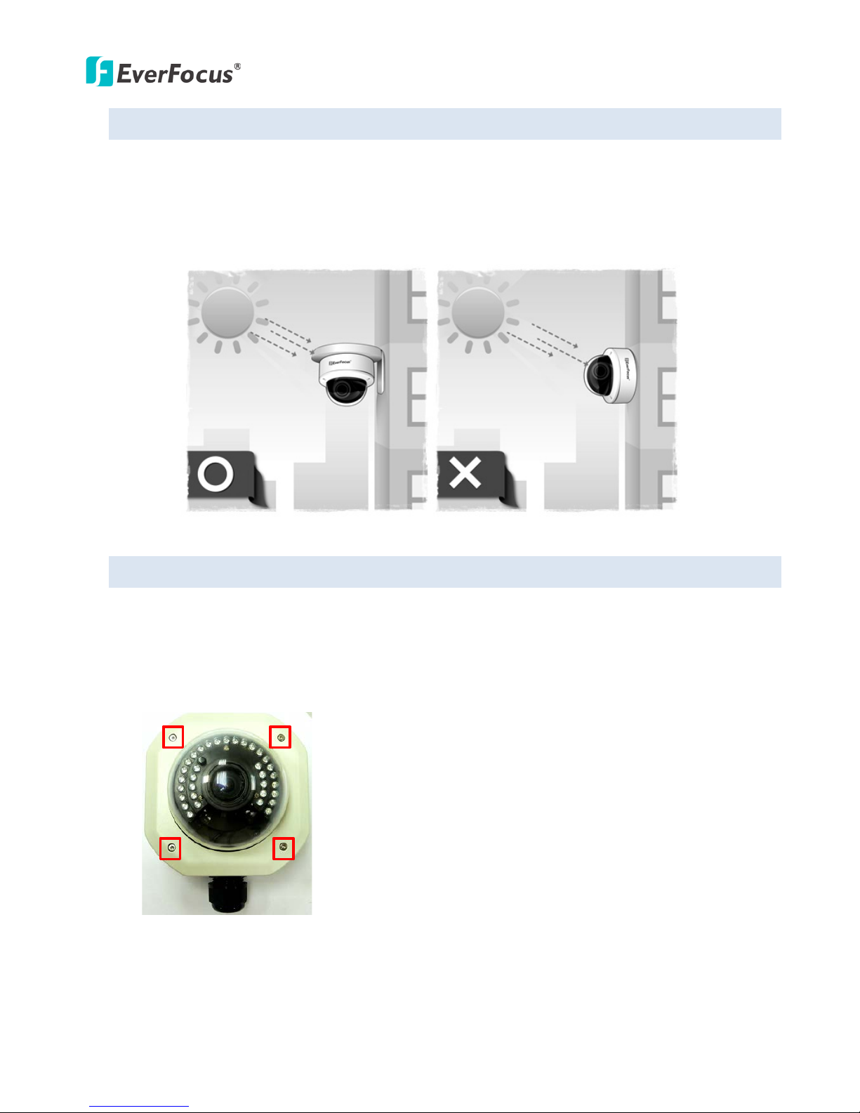
3. Try to avoid facing the camera toward the sun.
In some circumstances, direct sunlight may cause permanent damage to the sensor and/or internal
circuits, as well as creating unbalanced illumination beyond the capability of the camera to
compensate.
4. Keep the power cord away from water and other liquids and never touch the power cord with wet
hands.
Touching a wet power cord with your hands or touching the power cord with wet hands may result in
electric shock.
5. Never install the camera in areas exposed to oil, gas or solvents.
Oil, gas or solvents may result in equipment failure, electric shock or, in extreme cases, fire.
6. Cleaning
For cameras with interchangeable lenses, do not touch the surface of the sensor directly with the
hands. Use lens tissue or a cotton tipped applicator and ethanol to clean the sensor and the camera
lens. Use a damp soft cloth to remove any dirt from the camera body. Please do not use complex
solvents, corrosive or abrasive agents for cleaning of any part of the camera.
7. Do not operate the camera beyond the specified temperature, humidity or power source ratings.
Use the camera at temperatures within -40°C ~ 55°C / -40°F ~ 131°F (12 VDC) or -20 the camera at
temperatures wi; this device is not rated as submersible. The input power source is 12 VDC / PoE. Be
sure to connect the proper + / - polarity and voltage, as incorrect polarity or too high a voltage will
likely cause the camera to fail, and such damage is not covered by the warranty. The use of properly
fused or Class 2 power limited type supplies is highly recommended.
8. Mounting
Use care in selecting a solid mounting surface which will support the weight of the camera plus any
wind, snow, ice or other loading, and securely attach the camera to the mounting surface using
screws and anchors which will properly support the camera. If necessary (e.g. when mounting to
drop ceilings) use a safety wire to provide additional support for the camera.

iii
CONTENTS
1. Introduction ................................................................................................................................. 1
2. Overview ....................................................................................................................................... 2
3. Features ........................................................................................................................................ 3
4. Installation ................................................................................................................................... 4
4.1 Packing List ....................................................................................................................................... 4
4.2 Optional Accessories ........................................................................................................................ 4
4.3 Terminal Block .................................................................................................................................. 5
4.4 Important Notice for the Installation ............................................................................................... 6
4.5 Basic Installation .............................................................................................................................. 6
5. Accessing the User Interface ................................................................................. 13
5.1 Checking the Dynamic IP Address .................................................................................................. 13
5.2 Settings for Microsoft Internet Explorer ........................................................................................ 15
5.3 Connecting the Camera to the Network ........................................................................................ 17
5.4 Live View Window .......................................................................................................................... 19
6. Playback ............................................................................................................. 22
6.1 Playback Window ........................................................................................................................... 22
6.2 Setting Up the Playback Function .................................................................................................. 24
6.2.1 Preparing the SD Card ........................................................................................................ 24
6.2.2 Testing the Playback Function ............................................................................................ 24
6.3 Playing Back Using ARV Viewer ...................................................................................................... 26
7. Settings .............................................................................................................. 27
7.1 System Info ..................................................................................................................................... 27
7.1.1 Information .......................................................................................................................... 27
7.1.2 Log ........................................................................................................................................ 28
7.2 User Config ..................................................................................................................................... 29
7.2.1 Live View Config ................................................................................................................... 29
7.2.2 Recording/Snapshot ............................................................................................................. 30
7.2.3 Language .............................................................................................................................. 31
7.3 Network ......................................................................................................................................... 32
7.3.1 Network ............................................................................................................................... 32
7.3.2 DDNS .................................................................................................................................... 34
7.3.3 SMTP / FTP ........................................................................................................................... 36
7.3.4 HTTPS ................................................................................................................................... 38

iv
7.3.5 SNMP .................................................................................................................................... 41
7.3.6 Network Alarm ..................................................................................................................... 41
7.4 Video .............................................................................................................................................. 42
7.4.1 Multi Streaming ................................................................................................................... 42
7.4.2 Camera ................................................................................................................................. 44
7.4.3 Advanced .............................................................................................................................. 47
7.4.4 ROI (Region of Interest) ........................................................................................................ 61
7.4.5 Privacy Mask ........................................................................................................................ 62
7.4.6 Schedule ............................................................................................................................... 63
7.5 Audio .............................................................................................................................................. 64
7.6 User ................................................................................................................................................ 65
7.6.1 User Information .................................................................................................................. 65
7.6.2 IP Address Filter ................................................................................................................... 67
7.7 Event .............................................................................................................................................. 68
7.7.1 Event Settings ....................................................................................................................... 68
7.7.2 Motion Detection ................................................................................................................. 71
7.7.3 Tamper Detection................................................................................................................. 72
7.7.4 Alarm I/O .............................................................................................................................. 72
7.7.5 Schedule ............................................................................................................................... 73
7.8 System ............................................................................................................................................ 74
7.8.1 Date/Time ............................................................................................................................ 74
7.8.2 Daylight Saving ..................................................................................................................... 75
7.8.3 SD Card ................................................................................................................................. 75
7.8.4 Maintenance ........................................................................................................................ 76
8. Upgrading Firmware Using IP Utility ...................................................................... 78
9. Specifications ...................................................................................................... 80

EHNSeries
1
1. Introduction
TheEHNseriesisanoutdoorvandalproofIPdomedeliveringimagequalityofupto3‐megapixel.The
cameraisequippedwithaP‐Iris,whichenablesthecameratoautomaticallyandpreciselycontrolthebest
irispositioninvaryinglightingconditions,expandingthefocusareaoftheimagesandmeanwhileimprove
theimagesharpness.
TheEHNseriessupportsbothH.264andMJPEGcompressionformats.TheIP68‐ratedandIK10vandal
proofhousingmakeitsuitableforoutdooruse.TheIRLEDsarealsoimplementedforinfraredillumination
innightvisionapplications.
TheEHNseriesfeaturestheWideDynamicRange(WDR)function,whichcanprovideclearimageseven
underbacklightcircumstanceswhereintensityofilluminationcanvaryexcessively.Abuilt‐inSDHCcard
slotandPoweroverEthernet(IEEE802.3at)featuresarealsoprovided.Youcanpowerthecameraover
thenetworkorbyconnectingthecameratoa12VDCpowersupply.SincetheEHNseriesconformsto
ONVIF/PSIAforcompatibilitywithothernetworkvideodevices,itinteroperateswithawidevarietyof
hardwareandsoftwaresystems.YoucanalsouseEverFocus’MobileApplicationstoremotelyviewthelive
viewsofthecamerasthroughyourhandhelddevices;oruseEverFocus’CMStoremotelymanagemultiple
IPdevicesconnectedontheLANorWAN.
TheEHNSeriesModels
ModelName Megapixel P‐Iris WDR
EHN3160 1.3MP Yes Yes
EHN3260 2MP Yes Yes
EHN3340 3MP Yes No
SystemRequirement
Beforeinstalling,pleasecheckthatyourcomputermeetsthissystemrequirement.
OperatingSystem:MicrosoftWindowsXP/Vista(32‐bit)/7(32‐bit)
MicrosoftInternetExplorer7orabove
Note:ForusingtheInternetExplorer,somesettingsarerequired.Pleasereferto5.2Settingsfor
MicrosoftInternetExplorer.
EHN Series
2
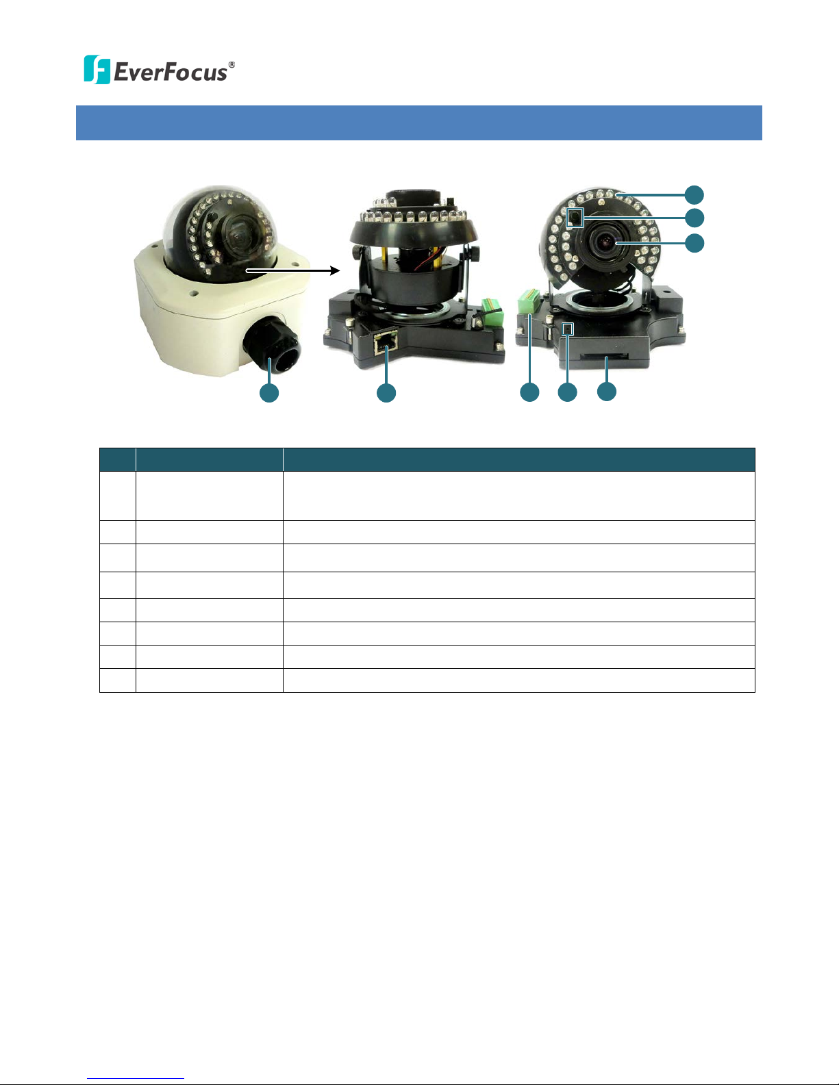
2. Overview
3
5
2
Camera Module
1
7
6
4
8
No. Item Name Descriptions
1 Cable Gland
Equipped with three plugs inserted in the cable conduits for
waterproofing.
2 LAN / PoE Connects to a 10/100 Ethernet or PoE.
3 Terminal Block A 12-pin terminal block. See 4.3 Terminal Block.
4 Reset Button Resets all configurations to the factory default settings.
5 SD / SDHC Slot For inserting an SD / SDHC card
6 Lens Varifocal lens with P-Iris control.
7 Light Sensor Detects lights.
8 IR LEDs 33 IR LEDs for infrared illumination in night vision applications.

EHN Series
3
3. Features
1/3” Panasonic CMOS sensor (for EHN3160 / 3260)
1/2.8” Sony CMOS sensor (for EHN3340)
Triple streams (stream 1 / 2 / 3 from H.264 or MJPEG)
Up to 30 fps at 1920 x 1080
Supports 15 fps at 2048 x 1536 (only for EHN3340)
Built-in P-Iris
Vandal-proof (IK10)
Weather-proof (IP68-rated)
Built-in SD / SDHC card slot
Removable IR-cut filter for Day / Night function
3-axis mechanism (pan / tilt / rotate)
One alarm input and output
Two-way audio
TV-out
Wide Dynamic Range (for EHN3160 / 3260)
Digital Slow Shutter (DSS)
2D / 3D Dynamic Noise Reduction (DNR)
Motion detection
10x digital zoom
Privacy mask
12 VDC / PoE
Multi-languages on Web interface
ONVIF / PSIA compliant
Supports EverFocus’ CMS and Mobile Applications
EHN Series
4
4. Installation
4.1 Packing List
Please check that there is no missing item in the package before installing.
• EHN Series Camera x 1 • Desiccant Bag x 2
• Base Plate Screw x 4 • Inner Paper x 1
• Screw Anchor x 4 • Software CD x 1
• Hexagon Screwdriver x 1 • Quick Installation Guide x 1
Note:
1. Equipment configurations and supplied accessories vary by country. Please consult your local
EverFocus office or agents for more information. Please also keep the shipping carton for
possible future use.
2. Contact the shipper if any items appear to have been damaged in the shipping process.
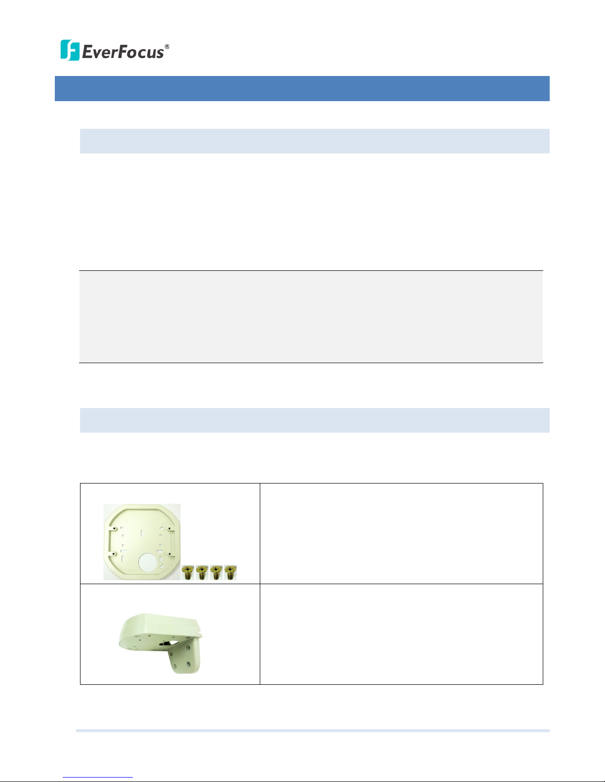
4.2 Optional Accessories
You can use the optional accessories to expand the capabilities and versatility of the camera. Please
contact your dealer for more information.
• One Adapter Plate with 4 Screws
The Adapter Plate is designed for wiring the cables through
the bottom of the camera case. For details on how to wire
the cables through the bottom of the camera, please refer
to 4.5 Basic Installation.
• L-Shaped Mounting Bracket
To prevent the camera from being damaged by direct
sunlight, it is strongly recommended to use the L-Shaped
Mounting Bracket to mount the camera to the wall. For
details on mounting the camera to the wall using the
L-Shaped Mounting Bracket, please refer to 4.4 Important
Notice for the Installation.
EHN Series
5
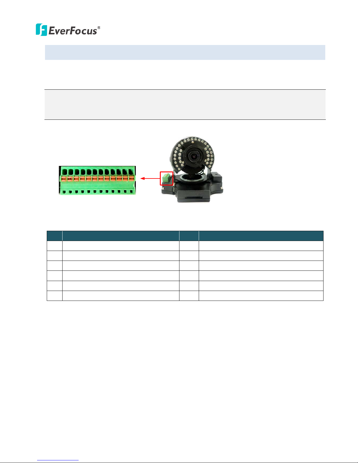
4.3 Terminal Block
The I/O terminal block, located on the camera module, can be used to develop applications for alarm
input and output, two-way audio, TV-output or a variety of other functions.
Note:
1. You can unplug the terminal block from the camera module for easier wiring.
2. Microphones with external power supplies are required.
Camera Module
1 2 3 4 5 6 7 8 9 10 11 12
Pin Assignment
No. Functions No. Functions
1 12 VDC Input 7 Audio Input C (Line-in)
2 Digital GND 8 Audio GND
3 Alarm Output C 9 Audio Output
4 Alarm COM C 10 Audio GND
5 Alarm Input C 11 CVBS Output
6 Digital GND 12 Digital GND
EHN Series
6
4.4 Important Notice for the Installation
If you want to mount the camera on the wall where direct sunlight may occur, it is strongly
recommended to mount the camera using the L-Shaped Mounting Bracket to prevent the camera from
being damaged by direct sunlight. Please refer to the Quick Installation Guide of L-Shaped Mounting
Bracket for more details.
4.5 Basic Installation
Follow the steps below to install the EHN IP camera to the wall.
To mount the camera to the wall and connect the cables to the related devices:
1. Unscrew the four screws and remove the cover from the camera.
EHN Series
7
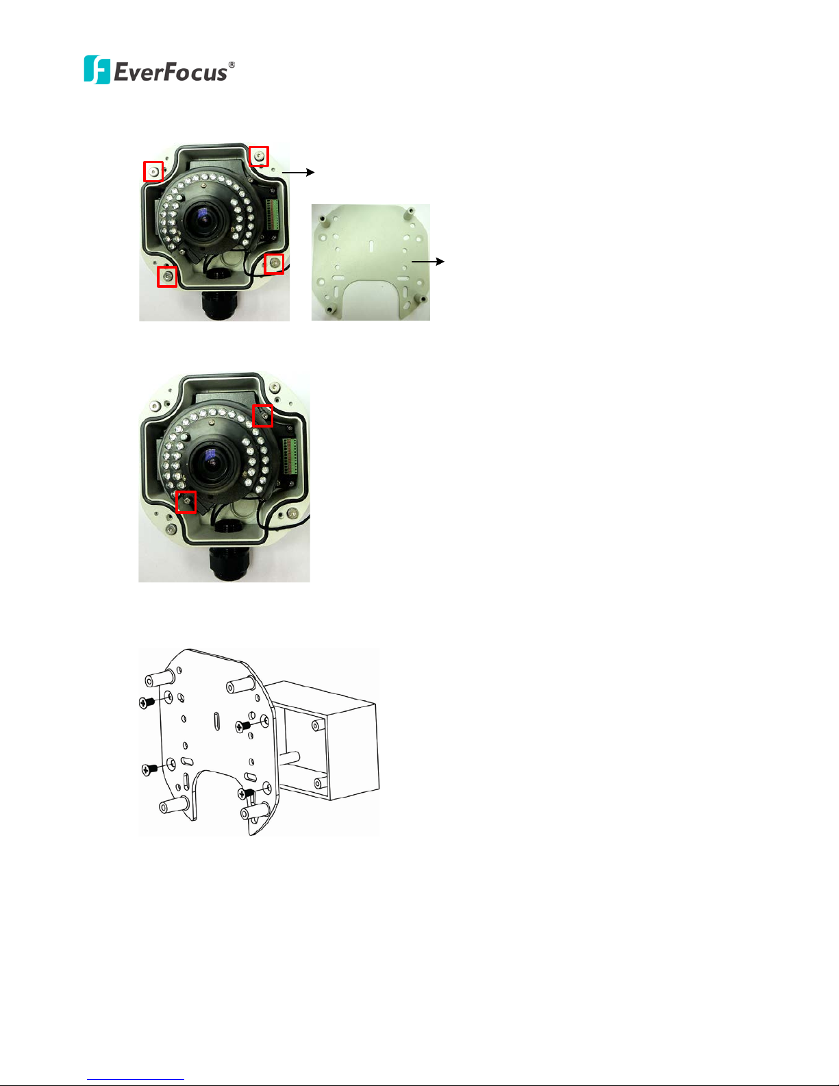
2. Unscrew the four screws and remove the Base Plate from the Camera Case.
Camera Case
Base Plate
3. Unscrew the two screws and take out the camera module.
4. Screw the Base Plate to the wall / Wiring Box using the supplied four screws.
Base Plate
Wiring Box
EHN Series
8
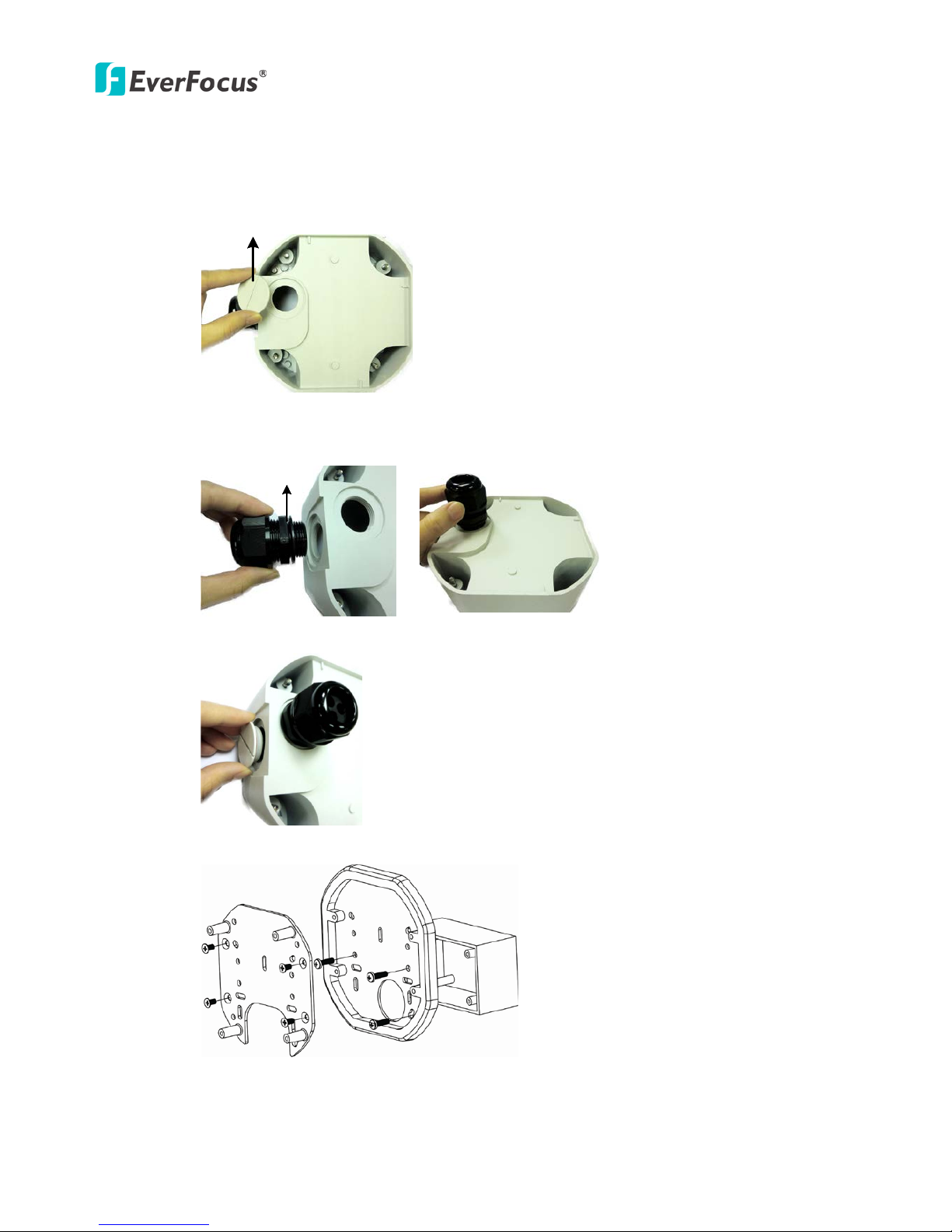
If you want to wire the cables through the bottom of the Camera Case, follow the steps below:
a. Remove the Circle Plate on the bottom of the Camera Case. You can simply loosen the Circle
Plate using a coin.
Circle Plate
Camera Case
b. Loosen and remove the Cable Gland from the Camera Case. Screw the Cable Gland to the
hole on the bottom of the Camera Case.
Cable Gland
Camera Case
c. Screw the Circle Plate to the side hole on the camera Case.
d. Screw an Adapter Plate between the Base Plate and Wiring Box.
Base Plate
Wiring Box
Adapter Plate
EHN Series
9
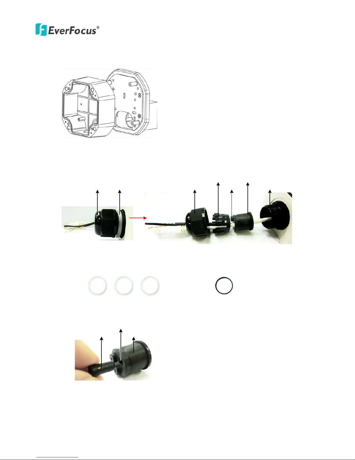
5. Screw the Camera Case back to the Base Plate.
Base Plate
Camera Case
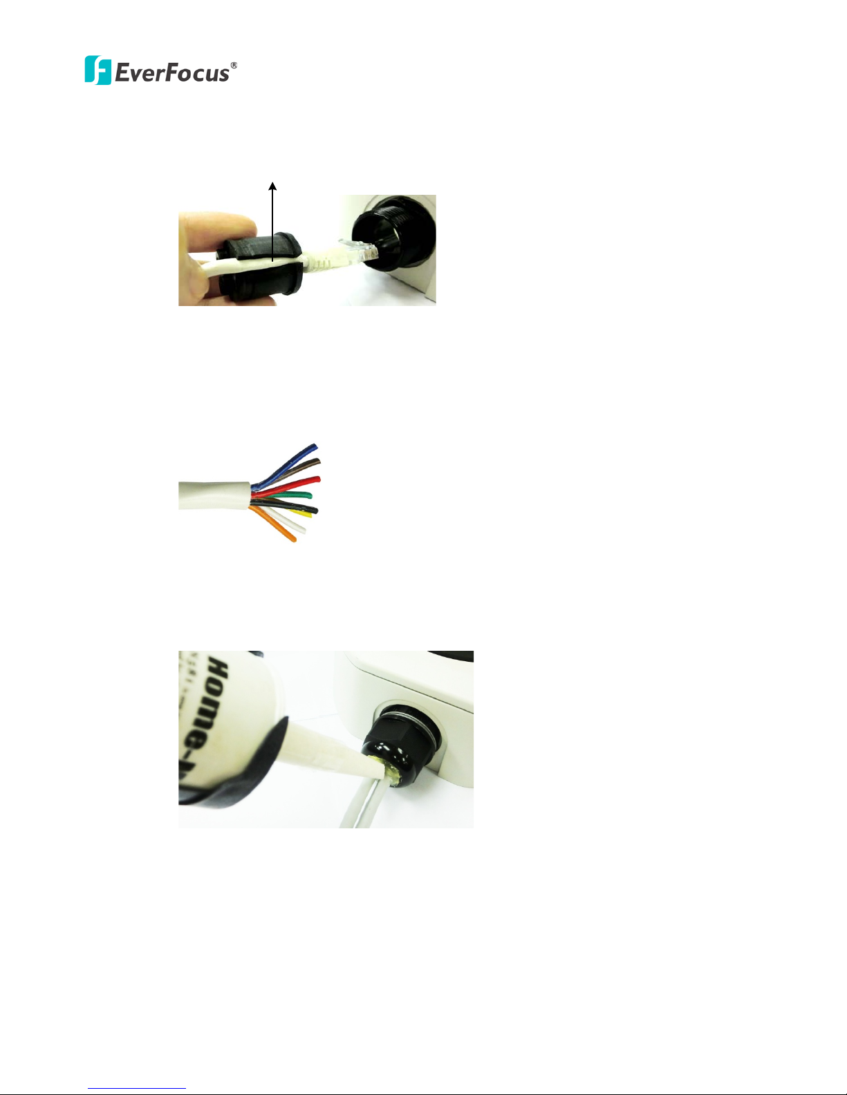
6. Insert the network / PoE cable or the additional cables through the Cable Gland. Up to three
cables can be inserted. Note that except the network / PoE cable, additional wires have to be
bundled into a cable with diameter ranging from 5.3mm to 6.4mm (see Step d below).
Screw BodyScrew Cap
Stopper Claw
Plug
Stopper
Adjustment Ring(s)
Cable Gland Cable Gland
Screw Cap
a. Keep the supplied 6 Adjustment Rings for waterproofing.
• Transparent x 5 (1 mm thickness)
• Black x 1 (0.5 mm thickness)
b. Remove the Plug(s) from the Stopper (depends on the number of cables inserted). One
Cable Conduit can only be inserted with one cable.
Plug Stopper
Cable Conduit
EHN Series
10
c. Insert the network / PoE cable through the Cable Conduit, if your network / PoE cable
already has a RJ-45 connector, then you can use the Slitted Cable Conduit.
Slitted Cable Conduit
d. Optionally insert the additional wires, such as power (if you want to power the camera
through a 12 VDC power source), alarm and audio cables, through the other Cable Conduit.
Note that one Cable Conduit can only be inserted with one cable. The Cable Conduit has
been tested to support cable diameter between 5.3mm and 6.4mm. Please refer to the
image below to bundle the lose wires before inserting to the Cable Conduit.
e. Tighten the Screw Cap all the way to the Adjustment Ring(s).
f. Due to the variable cable diameters, for better waterproofing, it is strongly recommended
that you apply silicon sealants to the inner Screw Cap.
7. Connect the network / PoE cable to the LAN / PoE port on the camera module.
8. If you have inserted additional wires, connect the wires to the terminal block. Please refer to 4.3
Terminal Block for pin assignment.
EHN Series
11
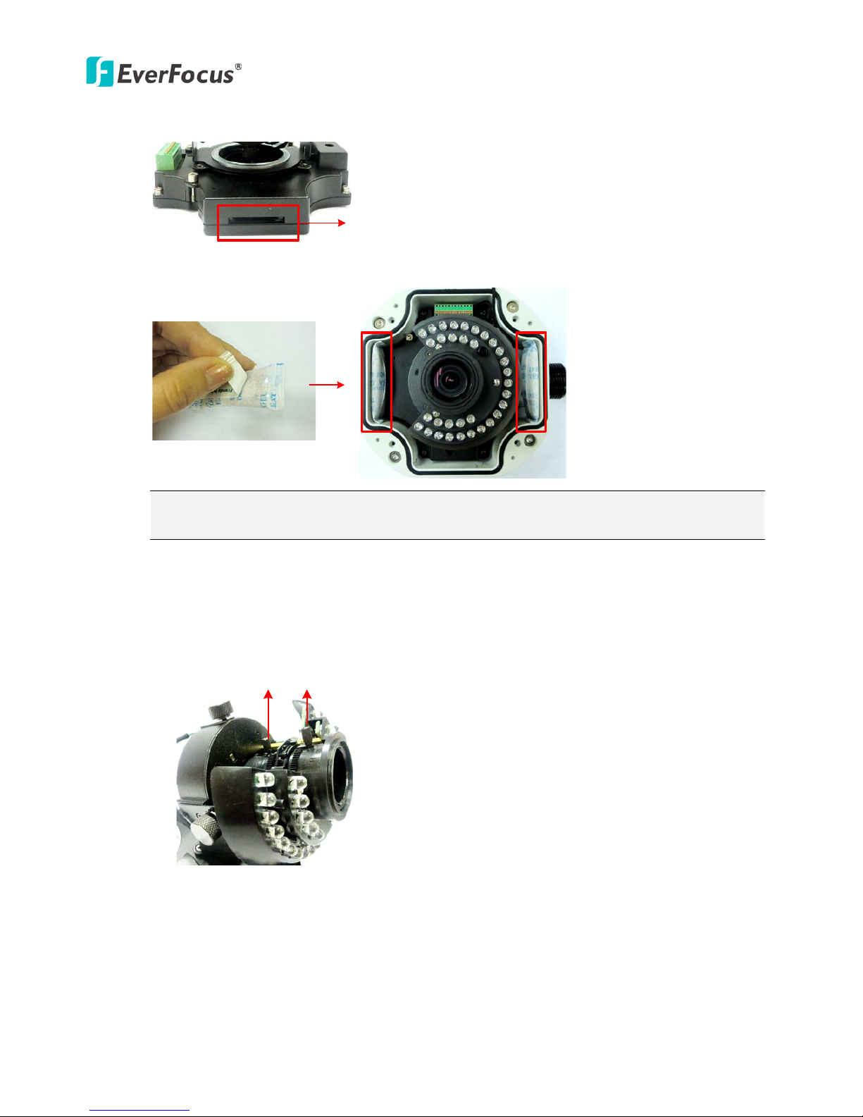
9. Optionally insert an SD / SDHC card to the card slot.
SD Card Slot
10. Stick the supplied 2 desiccant bags inside the camera case.
Note: It is highly recommended to replace the desiccant bags every time when you open the
camera.
11. Place and screw the camera module back to the camera case.
12. Access the camera live view for adjusting camera lens and angles. For details on how to access
the camera live view, see 5. Accessing the User Interface.
a. To adjust camera lens, use the Zoom / Focus screws.
Focus ScrewZoom Screw
EHN Series
12
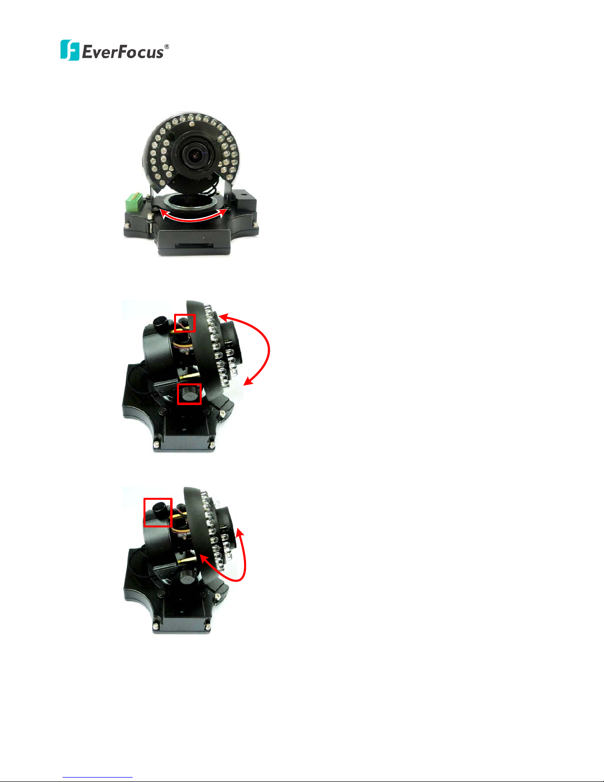
b. To adjust the camera to a desired angle:
Pan Adjustment: Simply turn left / right for the top camera module.
360°360°
Tilt Adjustment: Using the two tilt screws.
64°
Rotational Adjustment: Using the rotate screw.
180°
13. Screw the cover back to the camera case.
EHN Series
13
5. Accessing the User Interface
This section explains how to access the Web interface of the camera for configuration.
5.1 Checking the Dynamic IP Address
You can look up the IP address and access the Web interface of the camera using the IP Utility (IPU)
software included in the software CD. Please connect the IP camera in the same LAN of your computer.
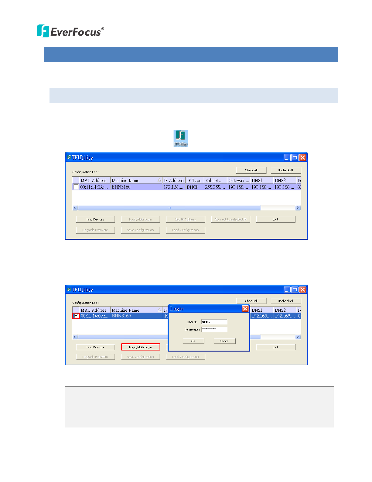
1. Install and then start the IPU program . The following dialog box appears.
2. IPU will automatically search the cameras connected in the LAN. The default network values of
the cameras will be displayed. By default, the network protocol of the camera is DH C P.
3. To configure the network settings, select a camera and then click Login/Multi Login to log in.
4. Type the user ID and password. Click OK.
Note:
1. The default user ID is user1 and the default password is 11111111.
2. If you select more than one camera that has the same user ID / password, you will be able
to log in several cameras at once.
EHN Series
14
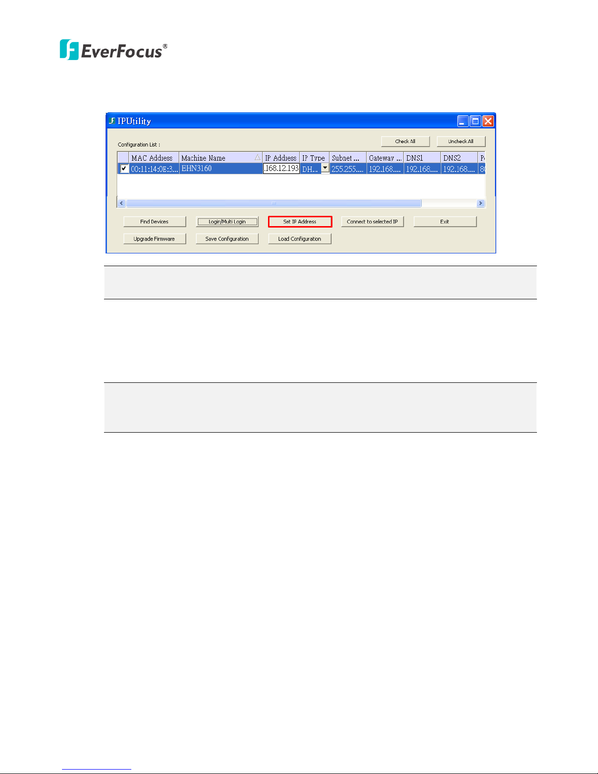
5. To change the IP settings, double-click the values in the column and type the numbers or select
an option. Click Set IP Address to save the settings.
Note: Most networks uses DHCP to assign IP addresses, if you are unsure of your network
settings, please consult your network administrators for configuration details.
6. To access the camera, highlight the camera and click Connect to Selected IP. The Internet
Explorer window pops up.
7. Type the user ID and password to log in. The Live View window of the camera appears.
Note: You might be required to download ActiveX, which is required to view the camera feed.
If asked, click "Yes". For more details on setting up the Microsoft Internet Explorer, please
refer to 5.2 Settings for Microsoft Internet Explorer.
EHN Series
15
5.2 Settings for Microsoft Internet Explorer
To enable Remote Live View, Firmware Upgrade and ActiveX Prompt on Internet Explorer, some
settings have to be complete. Please follow the steps below:
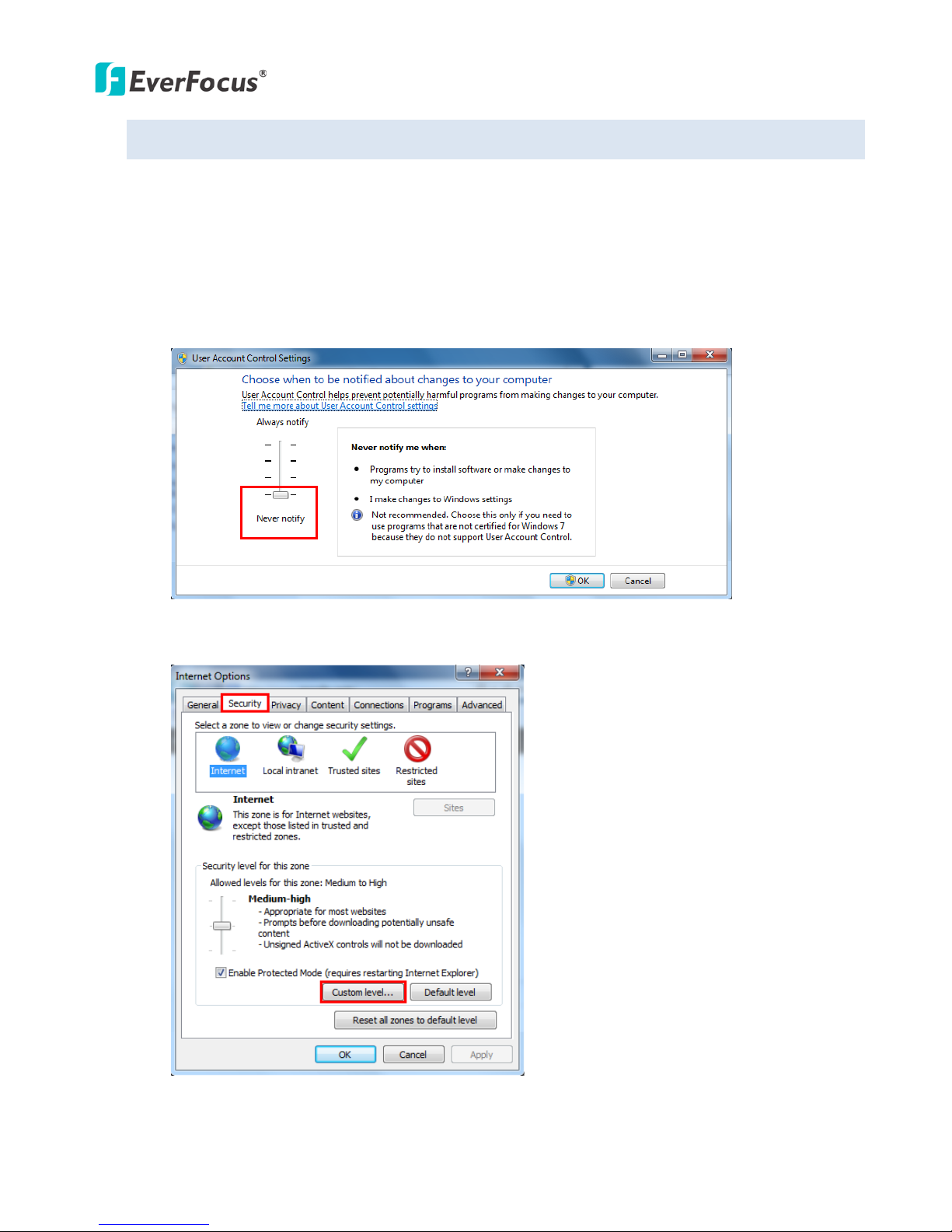
1. On the computer, click Start > Control Panel > System and Security > Action Center (click Change
User Account Control Settings), the User Account Control Settings window appears. Adjust the
slide bar to Never Notify and then click OK. Restart your computer if requested.
2. Open the Internet Explore, click Tools > Internet Options > Security Tab > Custom Level, the
Security Settings windows appears.
EHN Series
16
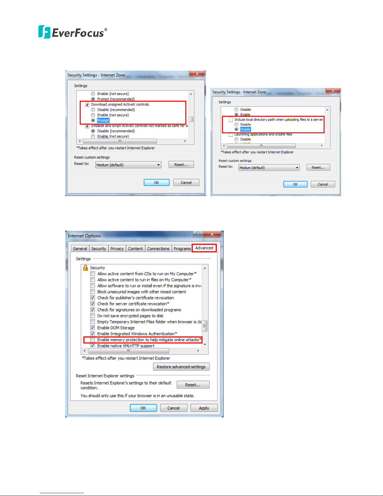
3. In the Download unsigned ActiveX controls field, select Prompt. In the Include local directory
path when uploading files to a server field, select Enable. Click OK.
4. In the Internet Options window, click the Advanced tab and then disable Enable memory
protection to help mitigate online attacks. Click OK.

EHN Series
17
5.3 Connecting the Camera to the Network
There are three methods to connect the IP camera to the network: Router or LAN Connection, Direct
High-Speed Connection and One-to-One Connection.
Router or LAN connection
This is the most common connection in which the IP camera is connected to a router and allows
multiple users on and off site to see the IP camera on a LAN/WAN (Internet). The camera must be
assigned an IP address that is compatible with its LAN. By setting up port forwarding on the router, you
can remotely access the cameras from outside of the LAN via the Internet. To remotely access the Web
interface of the IP camera, please refer to 7.3.2 DDNS. To set up port forwarding, please consult the
manual of the rou ter.
Straight-through LAN patch cable
Right: Pinout of a straight-through cable.
EHN Series
18
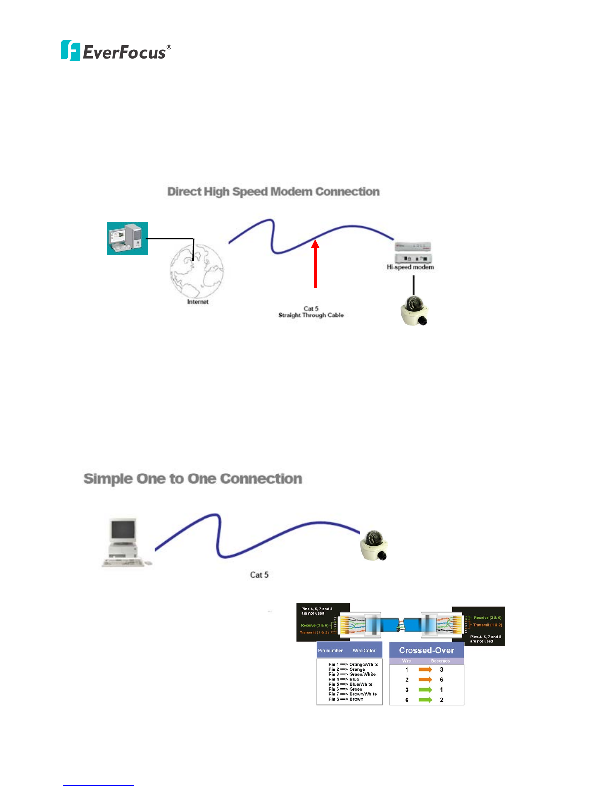
Direct High-Speed Connection
In a Direct High-Speed Connection, the camera connects directly to a modem without the need for a
router. You need to set the static or dynamic WAN IP address assigned by your ISP (Internet Service
Provider) in the camera’s configuration web pages. To access the camera, just type “http://xxx”, where
xxx is the IP address given by your ISP. If you have a dynamic IP address, this connection may require
that you use DDNS for a reliable connection. Please refer to 7.3.2 DDNS.
One-to-One Connection (Directly from PC to IP Camera)
You can connect directly without using a switch, router or modem. However, only the PC connected to
the camera will be able to view the IP camera. You will also have to manually assign a compatible IP
address to both the computer and the IP camera. Unless the PC has another network connection, the IP
camera will be the only network device visible to the PC. See the diagram below:
Pinout of straight patch cable
Right: Pinout of a crossed-over cable.
EHN Series
19
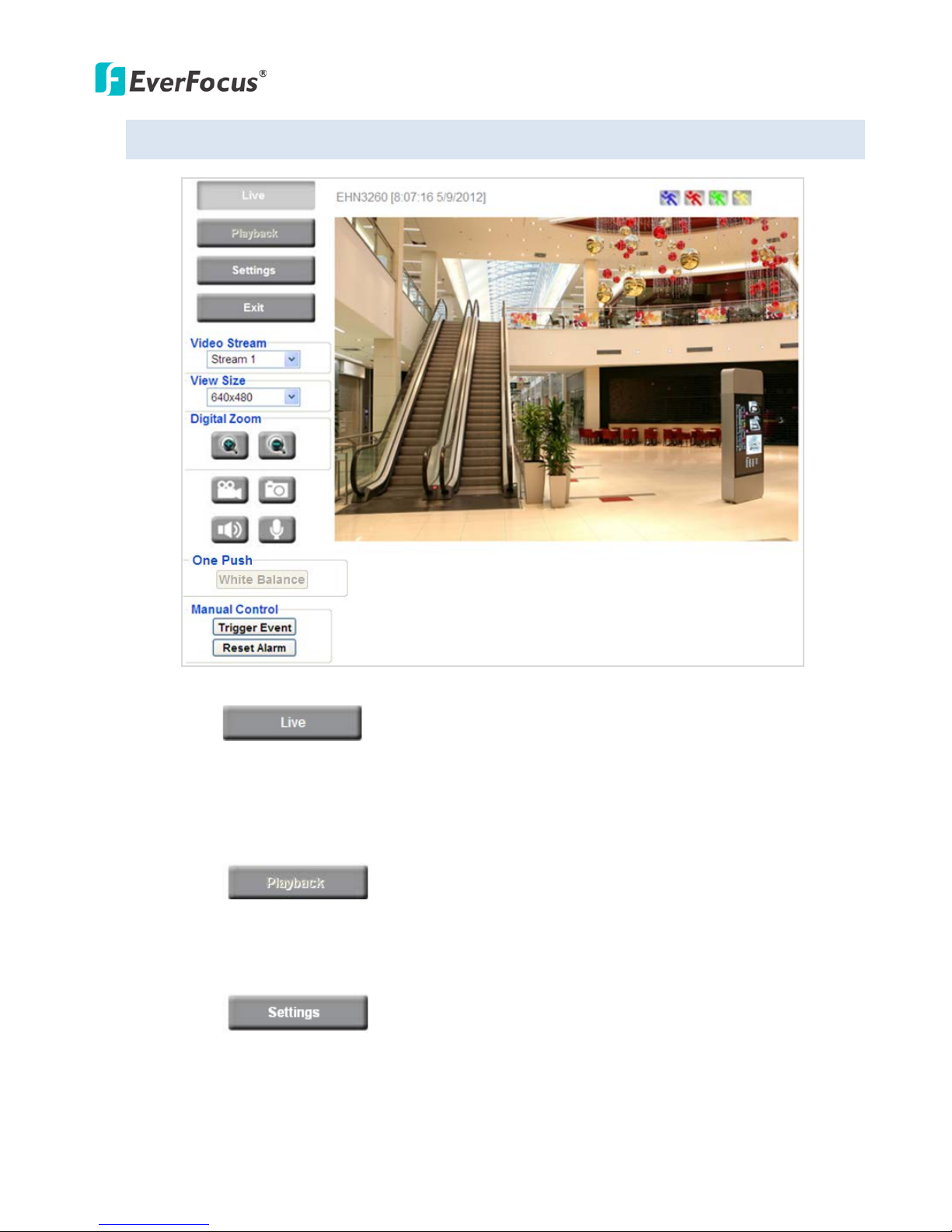
5.4 Live View Window
1. Press the button to display the "Live View" window. Double-click on the
image to show a full-screen display, double-click again or press ESC to return to the normal display.
If you experience video feed lag time (if connected via Internet), you can reduce the resolution or
limit the number of streams. See 7.4.1 Multi Streaming.
2. Press the button to play the recorded data directly from the on-camera SD
card (for this function to become active, you have to insert an SD card in the camera’s SD card slot.
See 7.8.3 SD Card.
3. Press the button to enter the Settings page. On the Settings page, there are
8 submenu sections: [System Info], [User Config], [Network], [Video], [Audio], [User], [Event] and
[System]. Click on the section buttons to open their configuration fields. See the Settings section
below for more information.
EHN Series
20
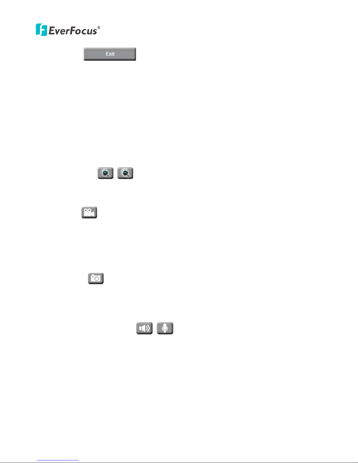
4. Press the button to exit the system and close this browser page.
5. Video Stream
Select the Video Stream (Stream 1, Stream 2 or Stream 3) that will be displayed in the video box on
the right. Stream 2 and Stream 3 are only selectable if you have enabled the stream. The default
setting is Stream 1 only. See 7.4.1 Multi Streaming.
6. View Size
Use this to select the appropriate view size and shape of the video box on the right. A smaller size
might increase transmission speed and video quality.
7. Digital Zoom
Click the Zoom In / Zoom Out buttons or roll the mouse wheel to zoom in / out the camera live view
up to 10x. Clicking on a magnified image will re-center the image around that point.
8. Record
The Record button is used to record the current video stream. Click the Record button to start / stop
recording. This icon is only for one-minute video recording. To record long-period recordings, please
set a recording schedule (see 7.7.5 Schedule). The location on your computer, where the image files
will be saved to, and file size can be specified in the submenu (see 7.2 User Config).
9. Snapshot
Click the Snapshot button to save a snapshot of the video image currently being displayed. The
location on your computer where the snapshot data will be saved can be specified in “Settings >
User Config > Recording / Snapshot” (see 7.2 User Config).
10. Play Audio / Transmit Audio
Click the “Play Audio” (speaker) and “Transmit Audio” (microphone) buttons to switch the sound
on/off for the speaker and microphone, respectively (if such external devices have been connected
to the camera).
EHN Series
21
11. One Push
This function is only available for EHN3160 / 3260. The One Push button can be displayed on the
live view window by enabling the Show One Push Buttons function on the User Config < Live View
Config Setting page (see 7.2.1 Live View Config). To enable the button (turned from faded to clear),
on the Video < Advanced Setting page, select One Push from the White Balance Settings Mode
drop-down list, and click the Apply button. Once this is done, pressing the One Push button on the
Live View Window will instruct the camera to adjust the white balance settings, and these settings
will be active until the button is pushed again. This is like a “semi-automatic” way to adjust white
balance to suit the user, if the Auto or Manual mode does not give the result the user wants.
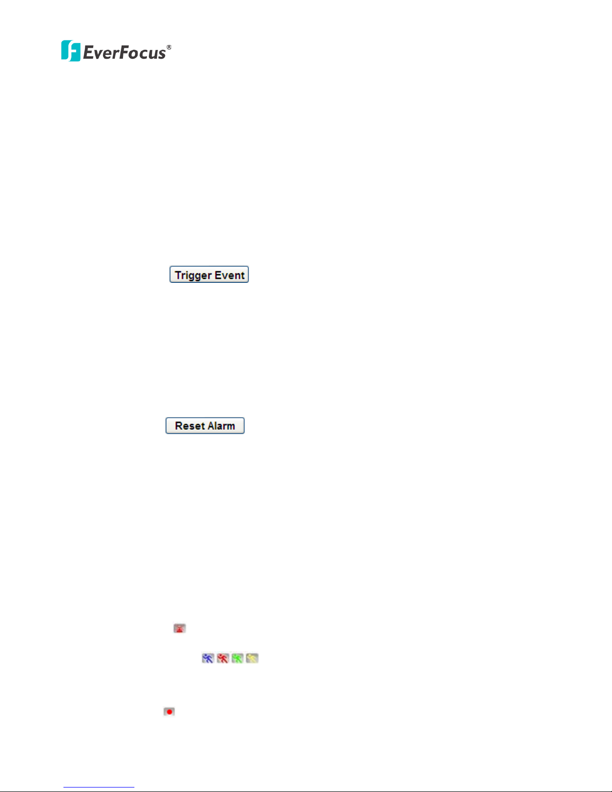
12. Manual Control
– Trigger Event
Press the “Trigger Event” button to trigger an event directly from the Live View window. If you have
configured an event (in the Event submenu) that will trigger a reaction (like a recording) when a
Manual Trigger event occurs, clicking this button will trigger that reaction. You can select what that
reaction will be. You can, for instance, set the camera to record the audio/video feed to the SD card
on board the camera. You can then click on the Playback button to open the Playback page and
search for and play all such recordings that had been stored on the card. Such event actions will be
effective once they have been configured in the “Event” menu (see 7.7 Event).
– Reset Alarm
Press the “Reset Alarm” button to reset the alarm output remotely.
13. Status Display (info line that can be placed above video box or at bottom of page)
This shows the name of the camera that is currently active or being configured, current date/time
and current frame rate. You can activate these info displays in the Settings > User Config page (see
7.2 User Config).
14. Event signal icons (above video screen)
When an alarm or motion event is triggered, a signal icon will appear at the top right of the Live
View window to alert the user.
Alarm event icon : When an alarm is triggered, this icon appears.
Motion detection icons : The colors of these motion event icons correspond to the
colors of the motion trigger areas you have configured in the Motion Detection submenu (see 7.7.2
Motion Detection).
Recording icon : When the camera is recording to a PC-based folder, this icon appears.
 Loading...