

EverFocus EHN3261, EHN3361 Quick Installation Manual
EHN Series Vandal Proof IP Dome Camera
10x Optical Zoom, Auto Focus, True Day/Night, WDR, IP68, IK10
Quick Installation Guide
Copyright © EverFocus Electronics Corp,
Release Date: March, 2014
EHN3261/3361
3
5
2
Camera Module
1
6
7
4
8
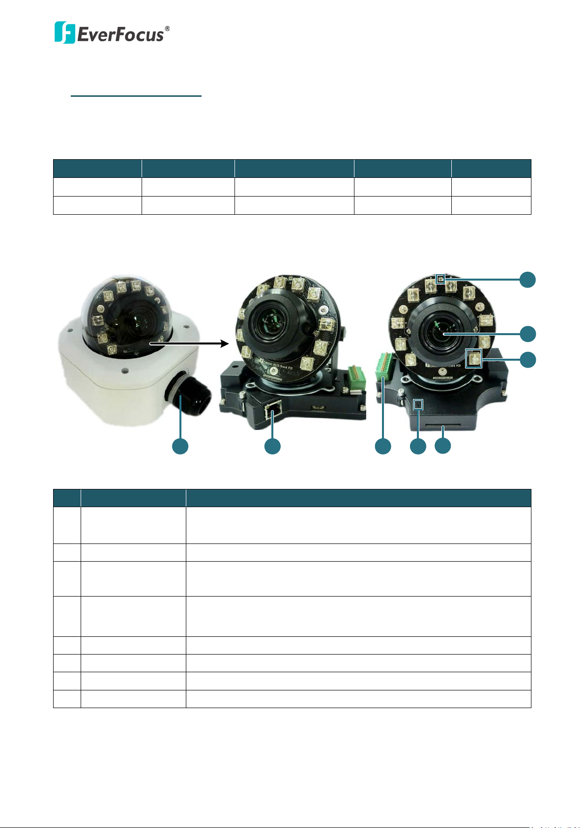
1. Physical Description
The EHN series vandal proof IP dome Camera features 10x optical zoom lens and is designed for
outdoor use. The series comes in two models: EHN3261 / 3361.
Model Name Megapixel
10x Optical Zoom Auto Focus
WDR
EHN3261 2 MP Yes Yes Yes
EHN3361 3 MP Yes Yes Yes
No. Item Name Descriptions
1
Cable Gland
Equipped with three plugs inserted in the cable conduits for
waterproofing.
2 LAN / PoE Connects to a 10/100 Ethernet or PoE.
A 12-pin terminal block. See Terminal Block later in this Quick
3 Terminal Block
Installation guide.
Resets all configurations to the factory default settings. Press and
4 Reset Button
hold the Reset Button for 10 seconds by using a pen or a paper click.
5 SD / SDHC Slot For inserting an SD / SDHC card
6 IR LEDs 10 IR LEDs for infrared illumination in night vision applications.
7 Lens 10x optical zoom, auto focus, DC Iris, F1.8-360C.
8 Light Sensor Detects lights.
1
EHN3261/3361
2
System Requirement
Before installing, please check that your computer meets these system requirements.
• Operating System: Microsoft Windows XP / Vista (32-bit) / 7 (32-bit)
• Microsoft Internet Explorer 7 or above
Packing List
• EHN Series Camera x 1 • Desiccant Bag x 2
• Base Plate Screw x 4 • Inner Paper x 1
• Screw Anchor x 4 • Software CD x 1
• Hexagon Screwdriver x 1 • Quick Installation Guide x 1
Note:
1. Equipment configurations and supplied accessories vary by country. Please consult your local
EverFocus office or agents for more information. Please also keep the shipping carton for
possible future use.
2. Contact the shipper if any items appear to have been damaged in the shipping process.
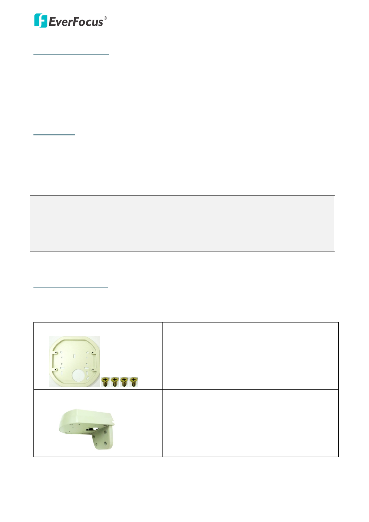
Optional Accessories
You can use the optional accessories to expand the capabilities and versatility of the camera. Please
contact your dealer for more information.
• One Adapter Plate with 4 Screws
The Adapter Plate is designed for wiring the cables
through the bottom of the camera case. For details on
how to wire the cables through the bottom of the
camera, please refer to the User’s Manual in the CD.
• L-Shaped Mounting Bracket
To prevent the camera from being damaged by direct
sunlight, it is strongly recommended to use the
L-Shaped Mounting Bracket to mount the camera to
the wall. For details on mounting the camera to the
wall using the L-Shaped Mounting Bracket, please refer
to the User’s Manual in the CD.
EHN3261/3361
3
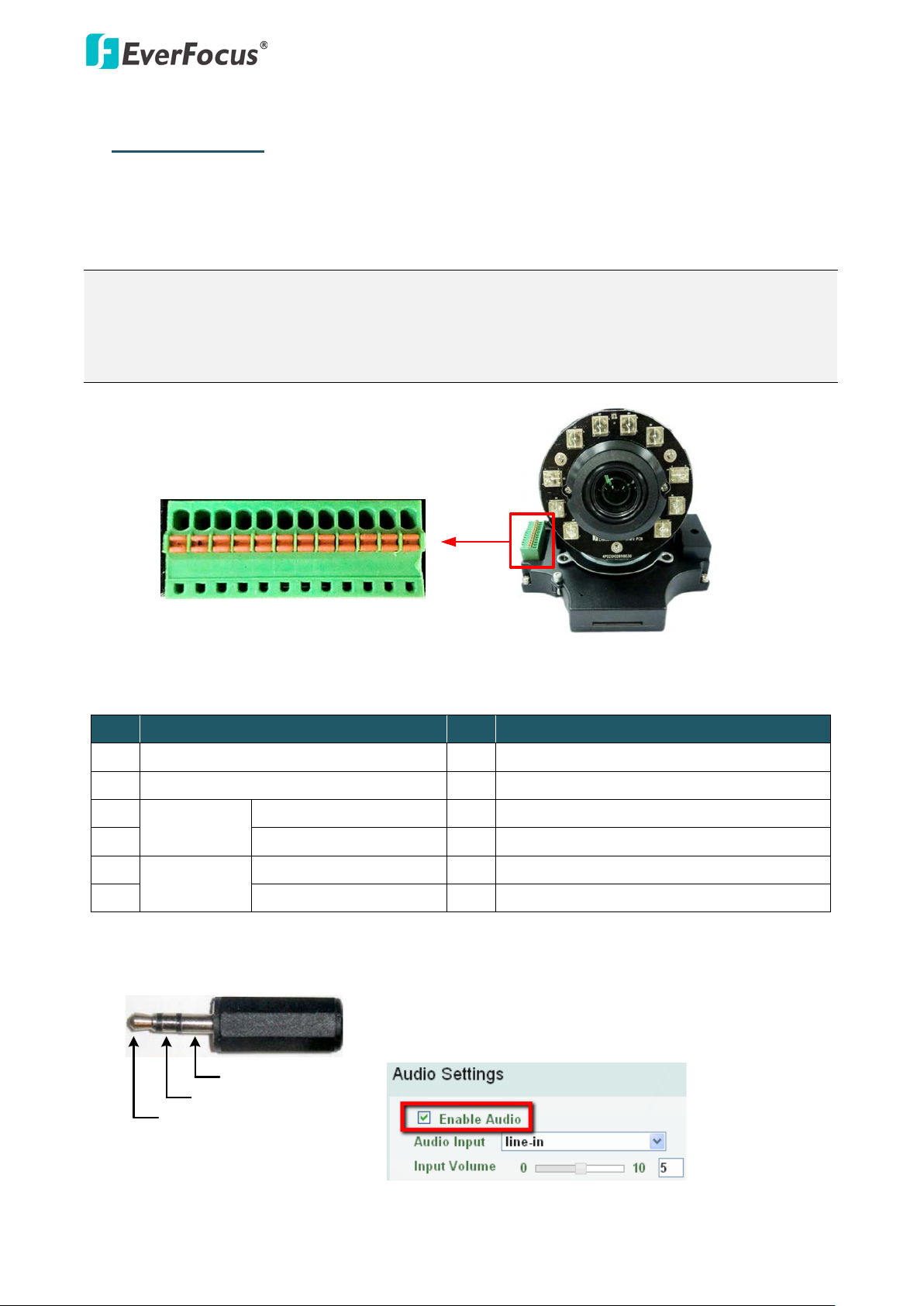
Camera Module
1 2 3 4 5 6 7 8 9 10 11 12
TRS Connector
Left Channel (Tip)
Right Channel (Ring)
Ground (Sleeve)
2. Terminal Block
The I/O terminal block, located on the camera module, can be used to develop applications for
alarm input and output, two-way audio, TV-output or a variety of other functions.
Note:
1. You can unplug the terminal block from the camera module for easier wiring.
2. Be sure to prepare microphones with TRS connector (see TRS Connector image below). Also,
microphones with a (built-in) amplifier and external power supply are required.
Pin Assignment
No. Functions No. Functions
1 12 VDC Input 7 Audio Input C (TRS Line-in)
2 Digital GND 8 Audio GND
3
Alarm Output C (+) 9 Audio Output
Alarm Out
4 Alarm COM C (-) 10 Audio GND
5
Alarm Input C (+) 11 CVBS Output
Alarm In
6 Digital GND (-) 12 Digital GND
To activate the Audio function, the Enable Audio must be
checked. See Audio Settings in 7.2.1 Streaming and Audio in
the User’s Manual.

EHN3261/3361
4
3. Installation
Important Notice for the Installation
If you want to mount the camera on the wall where direct sunlight may occur, it is strongly
recommended to mount the camera using the L-Shaped Mounting Bracket to prevent the camera
from being damaged by direct sunlight. Please refer to the Quick Installation Guide of L-Shaped
Mounting Bracket for more details.
Basic Installation
This installation guide provides the basic instructions on installing an EHN IP camera to the wall. For
details, please refer to the User’s Manual in the software CD.
To mount the camera to the wall and connect the cables to the camera:
1. Unscrew the four screws and remove the cover from the camera.
 Loading...