

EverFocus EHN, EZN1250, EHN1250, EZN1240, EHN2540 User Manual
...
EHN Series
EZN Series
Value IP Series Network Camera
2MP/5MP/8MP, H265, IR & WDR
User’s Manual
Copyright © EverFocus Electronics Corp.
Release Date: January, 2019

Copyright 1995-2019 EverFocus Electronics Corp.
Disclaimer
All the images including product pictures or screen shots in this document are for example only. The images
may vary depending on the product and software version. Information contained in this document is subject
to change without notice.
Copyright
All rights reserved. No part of the contents of this manual may be reproduced or transmitted in any form or by
any means without written permission of the EverFocus Electronics Corporation.
EverFocus
2F., No.12, Ln. 270, Sec. 3, Beishen Rd., Shenkeng Dist.,
New Taipei City 222, Taiwan
TEL: +886 2 2662 2338
FAX: +886 2 2662 3632
www.everfocus.com.tw

About this document
All the safety and operating instructions should be read and followed before the unit is operated. This
manual should be retained for future reference. The information in this manual was current when
published. The manufacturer reserves the right to revise and improve its products. All specifications are
therefore subject to change without notice.
Regulatory Notices
FCC Notice "Declaration of Conformity Information"
This equipment has been tested and found to comply with the limits for a Class A digital device,
pursuant to part 15 of the FCC Rules. These limits are designed to provide reasonable protection against
harmful interference in a residential installation. This equipment generates, uses and can radiate radio
frequency energy and, if not installed and used in accordance with the instructions, may cause harmful
interference to radio communications. However, there is no guarantee that interference will not occur in
a particular installation. If this equipment does cause harmful interference to radio or television
reception, which can be determined by turning the equipment off and on, the user is encouraged to try
to correct the interference by one or more of the following measures:
- Reorient or relocate the receiving antenna.
- Increase the separation between the equipment and receiver.
- Connect the equipment into an outlet on a circuit different from that to which the receiver is
connected.
- Consult the dealer or an experienced radio/TV technician for help.
Warning: Changes or modifications made to this equipment, not expressly approved by EverFocus or
parties authorized by EverFocus could void the user's authority to operate the equipment.
This device complies with part 15 of the FCC Rules. Operation is subject to the following two conditions:
(1) This device may not cause harmful interference, and
(2) This device must accept any interference received, including interference that may cause undesired
operation.
Value IP Series camera complies with CE and FCC.
i

Precautions
Do not install the camera near electric or magnetic fields.
Install the camera away from TV/radio transmitters, magnets, electric motors, transformers and audio
speakers since the electromagnetic fields generated from these devices may distort the video image or
otherwise interfere with camera operation.
Never disassemble the camera beyond the recommendations in this manual nor introduce materials
other than those recommended herein.
Improper disassembly or introduction of corrosive materials may result in equipment failure or other
damage.
Try to avoid facing the camera toward the sun.
In some circumstances, direct sunlight may cause permanent damage to the sensor and/or internal
circuits, as well as creating unbalanced illumination beyond the capability of the camera to compensate.
1. Keep the power cord away from water and other liquids and never touch the power cord with wet
hands.
Touching a wet power cord with your hands or touching the power cord with wet hands may result in
electric shock.
2. Never install the camera in areas exposed to oil, gas or solvents.
Oil, gas or solvents may result in equipment failure, electric shock or, in extreme cases, fire.
3. Cleaning
For cameras with interchangeable lenses, do not touch the surface of the sensor directly with the
hands. Use lens tissue or a cotton tipped applicator and ethanol to clean the sensor and the camera
lens. Use a damp soft cloth to remove any dirt from the camera body. Please do not use complex
solvents, corrosive or abrasive agents for cleaning of any part of the camera.
4. Do not operate the camera beyond the specified temperature, humidity or power source ratings.
Use the camera at temperatures within -30°C ~ 55°C / -22°F ~ 131°F, and humidity ≤ 95%; this device
is not rated as submersible. The input power source is 12VDC / PoE. Be sure to connect the proper + /
- polarity and voltage, as incorrect polarity or too high a voltage will likely cause the camera to fail,
and such damage is not covered by the warranty. The use of properly fused or Class 3 power limited
type supplies is highly recommended.
5. Mounting
Use care in selecting a solid mounting surface which will support the weight of the camera plus any
wind, snow, ice or other loading, and securely attach the camera to the mounting surface using
screws and anchors which will properly support the camera. If necessary (e.g. when mounting to
drop ceilings) use a safety wire to provide additional support for the camera.
ii

CONTENTS
1. Introduction……………………………………………………………………………………………………………………… 1
1.1 System Requirement ..................................................................................................................... 2
1.2 Features ........................................................................................................................................ 2
1.3 Packing List .................................................................................................................................... 3
2 Physical Description………………………………………………………………………………………………………… 4
2.1 Dimensions ................................................................................................................................... 5
2.2 Cables ............................................................................................................................................ 5
3 Installation………………………………………………………………………………………………………………………. 7
3.1 EHN Series ..................................................................................................................................... 7
3.2 EZN Series ..................................................................................................................................... 9
4 Accessing the Camera……………………………………………………………………………………………………… 10
4.1 Checking the Dynamic IP Address .............................................................................................. 10
4.2 Settings for Microsoft Internet Explorer ..................................................................................... 12
4.3 Connecting the Camera to the Network ..................................................................................... 13
5 Live View Window…………………………………………………………………………………………………………. 15
5.1 Playback ...................................................................................................................................... 16
5.1.1 Playback Panel ................................................................................................................ 17
5.1.2 Download ........................................................................................................................ 18
5.2 Display Setting ............................................................................................................................ 19
5.2.1 Live .................................................................................................................................. 19
5.2.2 Image .............................................................................................................................. 20
5.2.2.1 Hallway Display 22
5.2.3 Privacy Mask ................................................................................................................... 23
5.2.4 Audio ............................................................................................................................... 24
5.2.5 ROI .................................................................................................................................. 25
5.3 Record ......................................................................................................................................... 26
5.3.1 Record Setting ................................................................................................................. 26
5.3.2 Record Schedule ............................................................................................................. 27
5.4 Alarm Setting .............................................................................................................................. 28
5.4.1 Motion ............................................................................................................................ 28
5.4.2 I/O ................................................................................................................................... 29
5.4.3 Tamper Alarm ................................................................................................................. 30
5.4.4 Sound Detection ............................................................................................................. 31
5.5 Network Setting .......................................................................................................................... 32
iii

5.5.1 Network .......................................................................................................................... 32
5.5.2 Video Streaming ............................................................................................................. 34
5.5.3 Email ............................................................................................................................... 35
5.5.4 DDNS ............................................................................................................................... 36
5.5.5 IP Filter ............................................................................................................................ 37
5.5.6 RTSP ................................................................................................................................ 38
5.5.7 FTP .................................................................................................................................. 39
5.5.8 SNMP .............................................................................................................................. 40
5.5.9 HTTPS .............................................................................................................................. 40
5.6 Storage Setting............................................................................................................................... 41
5.6.1 Storage ............................................................................................................................ 41
5.6.2 Cloud Storage .................................................................................................................. 42
5.7 System Setting ............................................................................................................................ 44
5.7.1 General ........................................................................................................................... 44
5.7.2 User Account .................................................................................................................. 46
5.7.3 Firmware Upgrade .......................................................................................................... 48
5.7.4 Load Default .................................................................................................................... 48
5.7.5 System Reboot ................................................................................................................ 49
5.7.6 Import and Export .......................................................................................................... 49
5.7.7 Local Settings .................................................................................................................. 50
5.7.8 Log .................................................................................................................................. 51
5.7.9 Info .................................................................................................................................. 52
5.7.9.1 Performing the P2P Function ........................................................................... 52
5.8 Intelligent Setting ........................................................................................................................ 55
5.8.1 Record Schedule ............................................................................................................. 55
5.8.2 Detection ........................................................................................................................ 56
5.8.2.1 Perimeter Intrusion Detection ......................................................................... 56
5.8.2.2 Line-Crossing Detection ................................................................................... 58
5.8.2.3 Object Detection .............................................................................................. 60
5.8.2.4 Pedestrian Detection ....................................................................................... 62
5.8.2.5 Face Detection ................................................................................................. 64
5.8.2.6 Cross-Counting Detection ................................................................................ 66
5.8.3 Analysis ........................................................................................................................... 68
5.9 Color Setting ............................................................................................................................... 69
5.10 Lens Control ................................................................................................................................ 69
5.11 Live View Function Icons............................................................................................................. 70
iv

Value IP Series Network Cameras – H265, 2MP / 5MP / 8MP
1. Introduction
The Value IP series H.265 Outdoor IP camera provides 30fps at 2MP / 5MP / 8MP (4K) viewing resolution.
The series supports triple streams from H.265 or H.264 video compression formats. In same resolution, the
H.265 provides higher compression efficiency and lower bitrate comparing with H.264 codec, allowing
more efficient bandwidth and data storage usage. The Wide Dynamic Range function on the other hand
enables the IP camera to provide clear images even under back light circumstances where intensity of
illumination can vary excessively.
The motorized zoom lens models can provide the desired field of view with superior video quality in
precise focus. Equipped with an IP66 weather-proof housing, the Value IP series meets a wide variety of
needs for outdoor surveillance. Except 12VDC power supply, the series also supports Power over Ethernet
(IEEE 802.3af), which eliminates the need for power cables and thus reduce the installation costs.
The Value IP series conforms to ONVIF for compatibility with other network video devices. You can also use
EverFocus Mobile applications to remotely view the live views of the cameras through your iOS or android
handheld devices; or use EverFocus CMS to remotely manage multiple IP devices connected on the
network.
Series 2MP 5MP 8MP
EHN2850 / EHN2850-15 /
EHN Series EHN1250 / EHN1240 EHN2550 / EHN2540
EHN2840 / EHN2840-15
EZN2850 / EZN2850-15 /
EZN Series EZN1250 / EZN1240 EZN2550 / EZN2540
EZN2840 / EZN2840-15
Lens Type Models
EHN1250 / EHN2550 / EHN2850 / EHN2850-15
2.8~12mm motorized lens
EZN1250 / EZN2550 / EZN2850 / EZN2850-15
EHN1240 / EHN2540 / EHN2840 / EHN2840-15
3.6mm fixed lens
EZN1240 / EZN2540 / EZN2840 / EZN2840-15
For more information on the product specifications, please refer to the datasheet of each product. To
download datasheet, please click Download on each Product page on EverFocus Website
www.everfocus.com.tw
1

Value IP Series Network Cameras – H265, 2MP / 5MP / 8MP
1.1 System Requirement
Before installing, please check that your computer meets the following system requirements.
Operating System:
32/64-bit: Windows 7, Windows 8, Windows 2008
32-bit: Windows 2003, Window XP, Windows 2000
CPU: Intel Core Duo II dual-core processor or higher
Memory: 1G or more Video memory: 256M or more
Display: 1024 × 768 or higher resolution
IE: IE 6.0 or higher version
Note: For using the Internet Explorer, some settings are required. Please refer to 4.2 Settings for
Microsoft Internet Explorer.
1.2 Features
• Progressive Scan CMOS sensor
• Equipped with 2.8~12mm motorized lens or 3.6mm fixed lens (depends on model)
• Triple-streaming from H.265 / H.264
• Supports Wide Dynamic Range
• Provides True Day/Night functionality with automatic IR filter operation
• Equipped with IR LEDs
• Supports video analytics
• Supports ONVIF (V17.06, Profile S, Profile G)
• Weather-proof IP66 rated
• Supports micro SD card slot
• Supports live monitoring via mobile Apps (iOS & Android)
• Supports PoE and 12VDC
2

Value IP Series Network Cameras – H265, 2MP / 5MP / 8MP
1.3 Packing List
Please check that there is no missing item in the package before installing.
EHN Series EZN Series
1. Camera x 1
2. MAC Address Sticker x 2
3. Cable Gland Kit x 1
4. Screw x 4
5. Screw Anchor x 4
6. Torx Wrench x 1
7. Mounting Sticker x 1
8. Quick Installation Guide x 1
1. Camera x 1
2. MAC Address Sticker x 2
3. Cable Gland Kit x 1
4. Screw x 3
5. Screw Anchor x 3
6. Hexagon Wrench x 1
7. Quick Installation Guide x 1
8. Software CD x 1
9. Software CD x 1
Note:
1. Equipment configurations and supplied accessories vary by country. Please consult your local
EverFocus office or agents for more information. Please also keep the shipping carton for possible
future use.
2. Contact the shipper if any items appear to have been damaged in the shipping process.
Optional Accessory
You can go to the product page on EverFocus’ website to check the related optional accessories. Please
click Accessories on each Product page on EverFocus Website www.everfocus.com.tw
3
Value IP Series Network Cameras – H265, 2MP / 5MP / 8MP
4
9
10
1
2
4
3
6
5
EHN Series
EZN Series
8
7
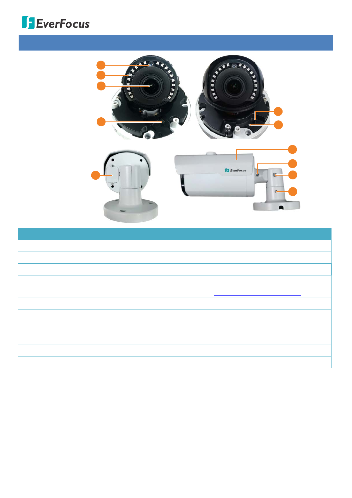
2 Physical Description
No. Item Name Descriptions
1 Light Sensor Detects lights.
2 IR LEDs IR LEDs for infrared illumination in night vision applications.
3 Lens Camera Lens.
4 Micro SD Card Slot
5 On-Board Joystick For adjusting Zoom and Focus.
6 Reset Button Press the button to restore the camera to factory default.
7 Sunshield Protect the camera from the direct sun rays.
8 Rotate Screw Loosen the Rotate Screws (on both sides) to adjust the rotating angle.
9 Tilt Screw Loosen the Tilt Screw to adjust the tilting angle.
10 Pan Screw Loosen the Pan Screw to adjust the angle.
Insert a micro SD card. Please go to the web page of the IP camera to see
the latest Storage Compatibility List. http://www.everfocus.com.tw
4
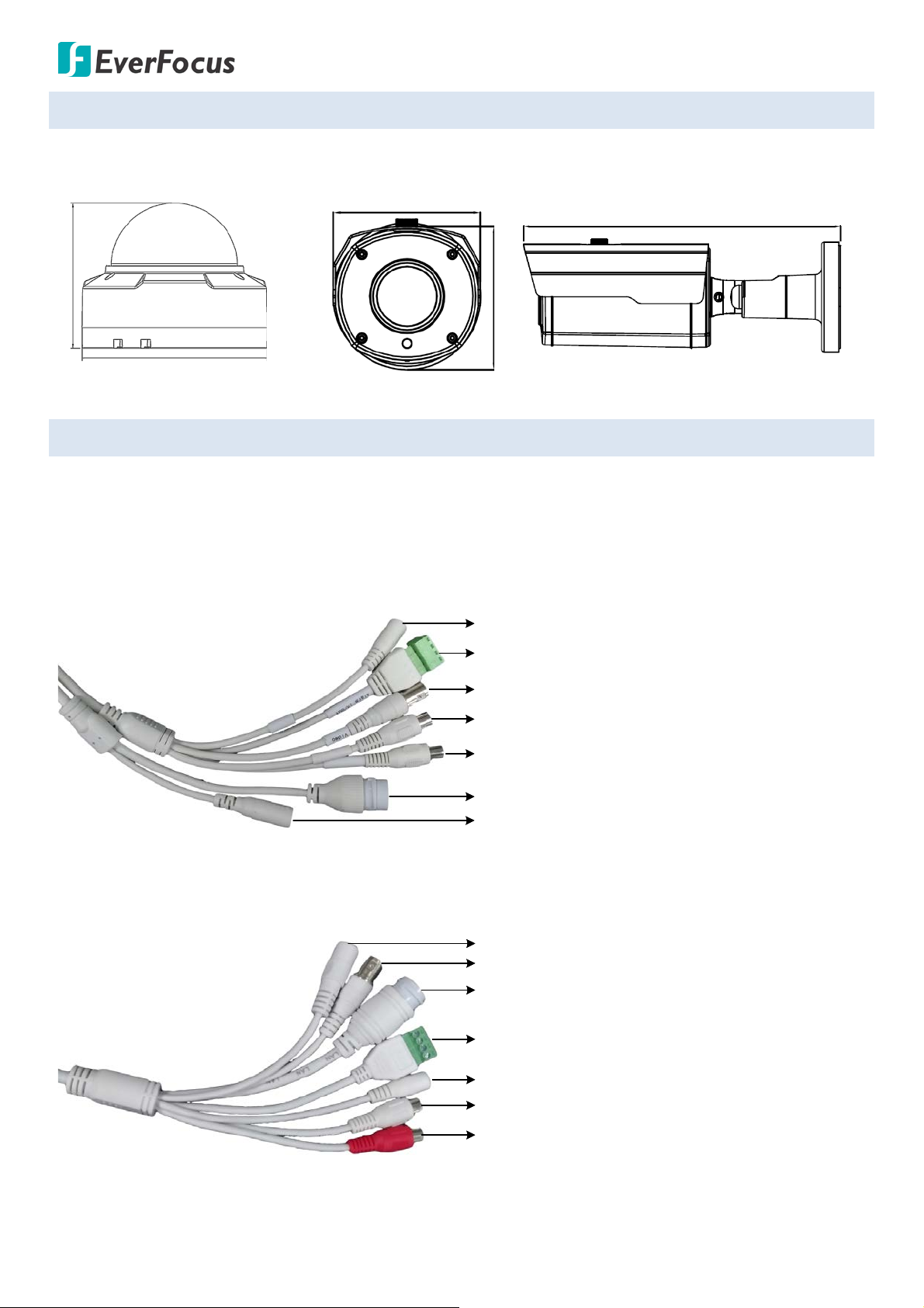
2.1 Dimensions
117.3mm / 4.62"
Ø 147mm / 5.79"
Ø 83.58mm / 3.29"
82.18mm / 3.24"
241.18mm / 9.5"
Alarm Input / Output
LAN / PoE Cable
Video Output (BNC)
12VDC Power Input
Reset Button
Audio Output
Audio Input
Alarm Input / Output
LAN / PoE Cable
Video Output (BNC)
12VDC Power Input
Reset Button
Audio Output (White)
Audio Input (Red)
Value IP Series Network Cameras – H265, 2MP / 5MP / 8MP
EHN Series
EZN Series
2.2 Cables
The cables provide connections for network, BNC video output, power, audio input / output and alarm
input / output. A Reset Button Cable is also provided. Please be noted that microphones / speakers with a
(built-in) amplifier and external power supply are required.
EHN Series
EZN Series
5
Value IP Series Network Cameras – H265, 2MP / 5MP / 8MP
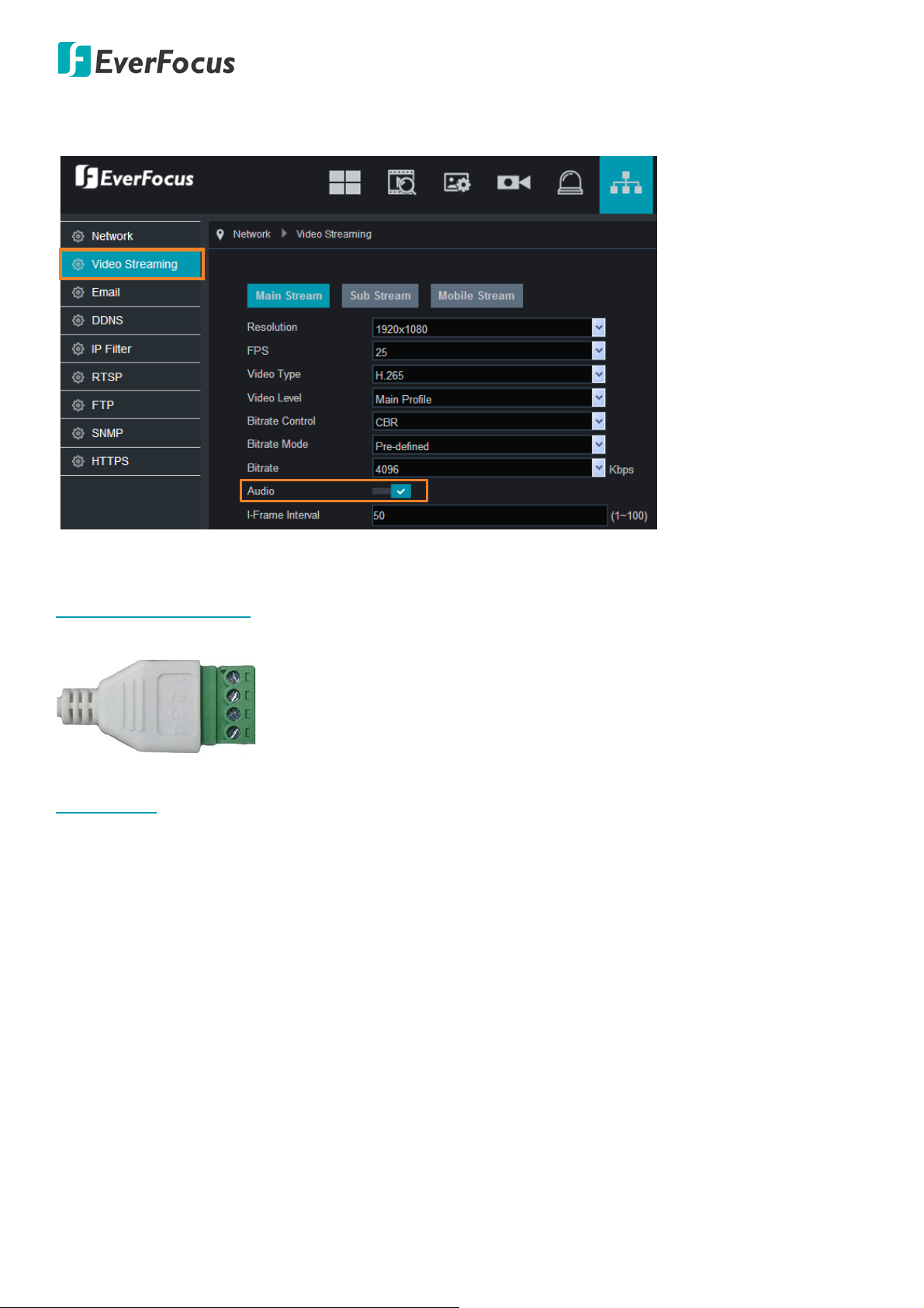
1
2
3
4
Alarm In
GND
COM
Alarm Out
Note: To activate Audio function, the Audio function must be enabled please refer to 5.5.2 Video
Streaming.
Alarm IO PIN Assignment
Reset Button
The Reset Button can be used to restore the camera to factory default. When the camera is powered up,
press the Reset Button about 8 seconds to reboot the camera.
6
Value IP Series Network Cameras – H265, 2MP / 5MP / 8MP
+
+
+
+
+
+
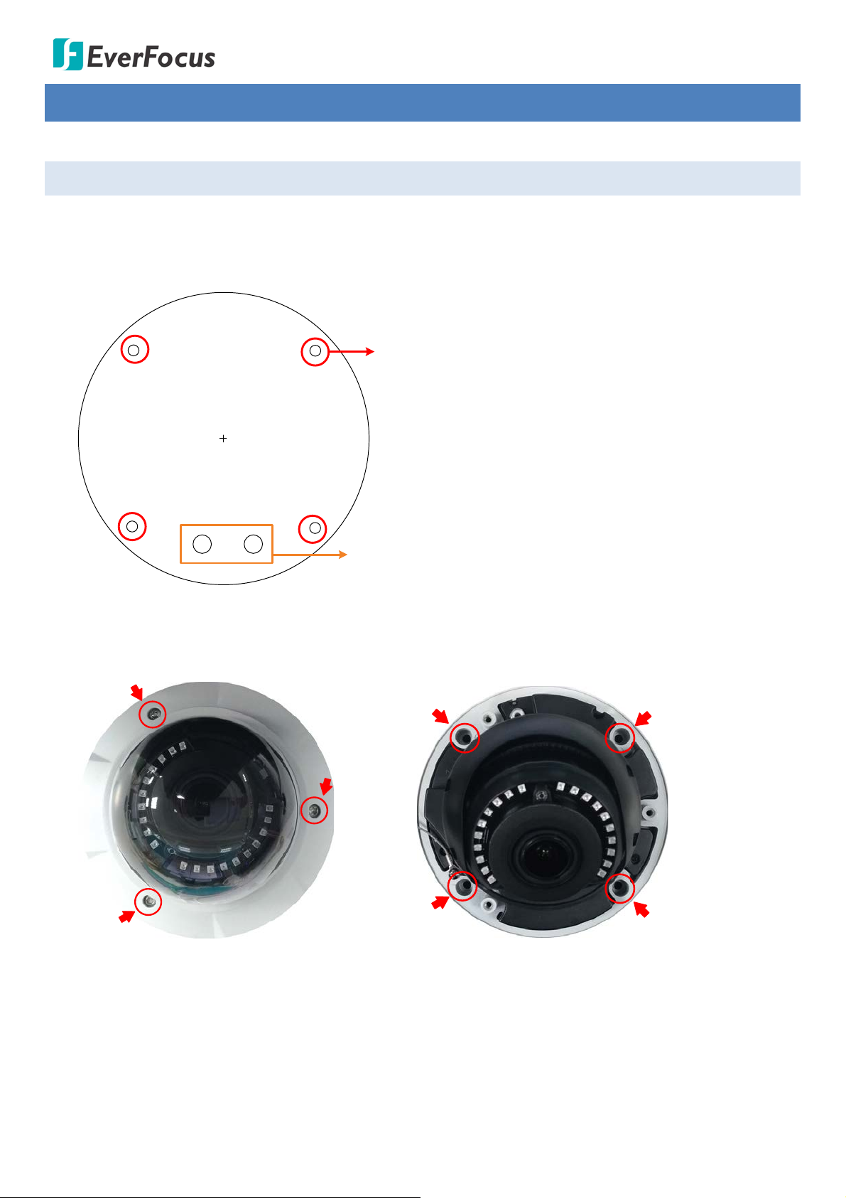
Screw Position x 4
Optionally drill the 2 Cable Holes if you
want to run the cables through the surface.
3 Installation
3.1 EHN Series
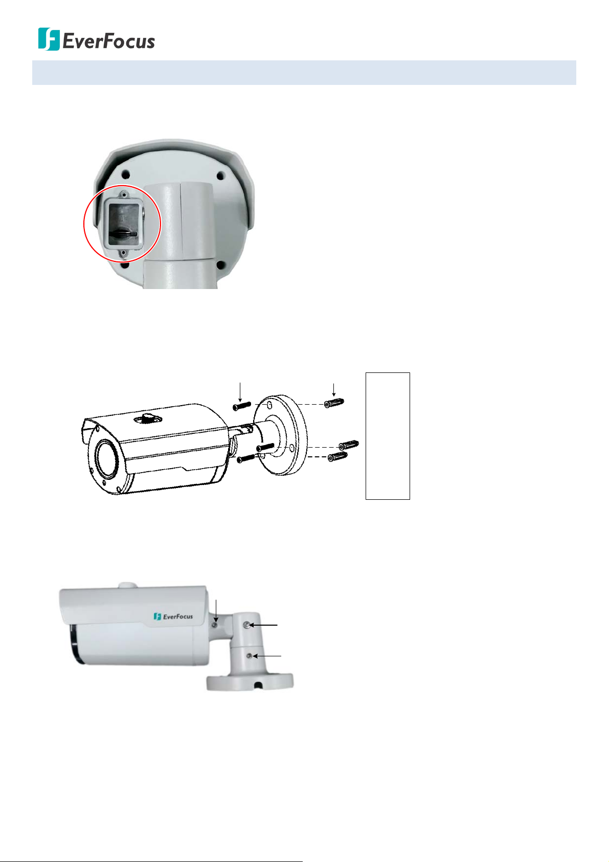
1. Stick the Installation Sticker on the surface to mark the 4 screw positions. Drill the 4 screw-depth holes
on the surface and then push the supplied 4 Screw Anchors into the screw holes. Optionally drill the
bottom 2 Cable Holes if you want to run the cables through the surface.
2. Remove the camera cover by unscrewing the 3 cover screws using the supplied Torx Wrench (Left
Image). Screw the camera base to the surface using the supplied 4 Screws (Right Image).
3. Optionally insert a micro SD card into the card slot (please refer to 2. Physical Description).
4. Adjust the pan / tilt / rotate angles of the camera.
5. Connect the camera to power. You can either connect the camera to a 12VDC power source or to a PoE
switch using the PoE cable.
7
Value IP Series Network Cameras – H265, 2MP / 5MP / 8MP
Waterproof Ring
Cable Gland
Stopper Screw Cap
RJ-
45
Cable
LAN/PoE Cable
Screw Cap
Cable Gland
Orange with white stripe
Orange
Green with white stripe
Blue
Blue with white stripe
Green
Brown with white stripe
Brown
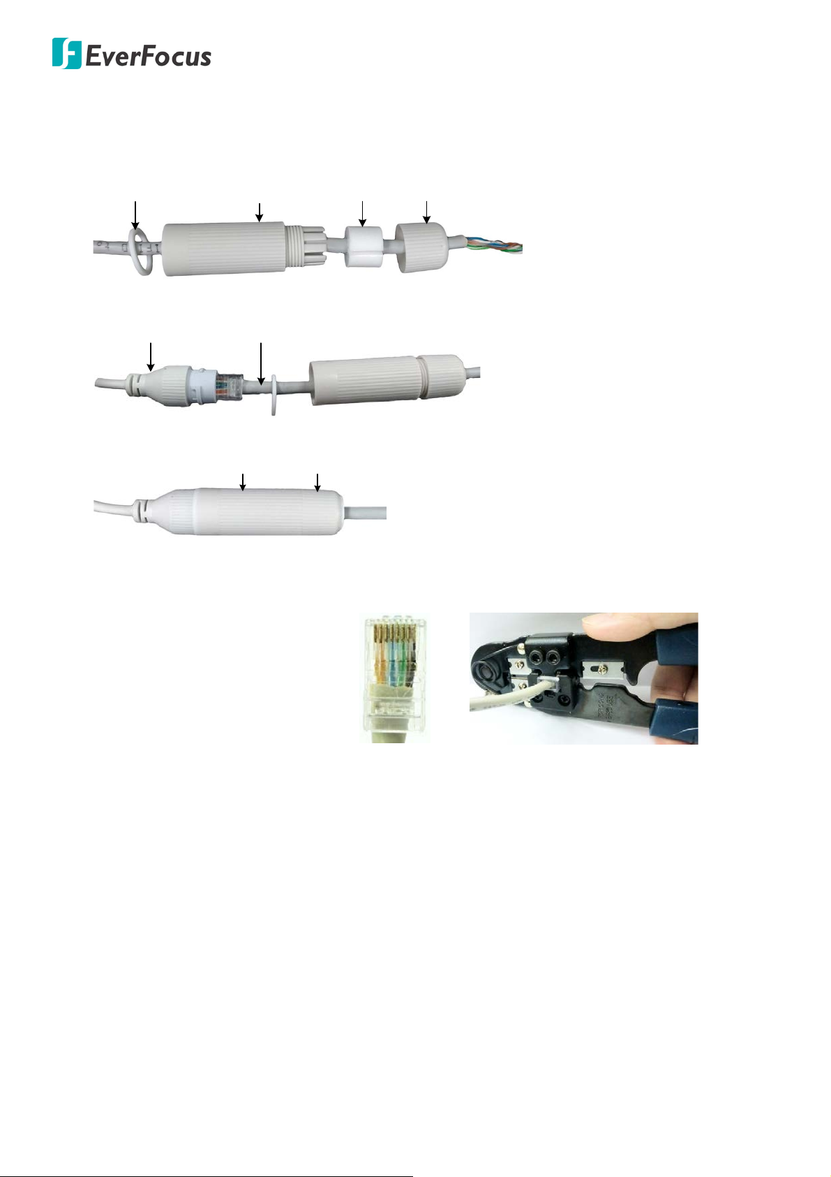
6. Connect the camera to the network using the supplied Cable Gland Kit.
a. Insert a RJ-45 network cable (without the RJ-45 connector on the one end) through the supplied
Waterproof Ring, Cable Gland, Stopper and Screw Cap accordingly.
b. Connect the RJ-45 cable to the LAN/PoE Cable of the camera.
c. Tightly screw the Cable Gland and Screw Cap to the Rugged RJ-45 Connector Cable.
d. Crimp the RJ-45 connector onto the RJ-45 network cable. Note that the wires should be placed into
the RJ-45 connector based on the following order (from left to right).
7. Screw the camera cover back to the camera.
8. Now you can access the camera live view. See 4. Accessing the Camera.
8
Value IP Series Network Cameras – H265, 2MP / 5MP / 8MP
Screw Anchor
Screw
Surface
Tilt Screw
Pan Screw
Rotate Screws (both sides)
3.2 EZN Series
1 Optionally insert a micro SD card into the card slot on the rear panel of the camera. To do this, unscrew
the 2 screw, remove the SD card slot cover and then insert the micro SD card.
2 Drill three holes on the surface according to the Camera Base and then push the supplied 3 Screw
Anchors into the holes. Drill another hole in the middle within the 3 screw holes if you wish to run the
wires into the surface. Screw the camera to the surface using the supplied 3 Screws.
3 Adjust the pan/tilt/rotate angles of the camera by loosen the Pan/Tilt/Rotate screws using the supplied
Hexagon Wrench.
4 Connect the camera to power. You can either connect the camera to a 12VDC power source or to a PoE
switch using the PoE cable.
5 Connect the camera to the network using the supplied Cable Gland Kit. Please refer to Step 6 in 3.1
EHN Series.
6 Now you can access the camera live view. See 4. Accessing the Camera.
9
Value IP Series Network Cameras – H265, 2MP / 5MP / 8MP
4 Accessing the Camera
This section explains how to access the Web interface of the camera for configuration.
4.1 Checking the Dynamic IP Address
You can look up the IP address of the IP camera using the IP Utility (IPU) program, which is included in the
Software CD. The IP Utility can also be downloaded from EverFocus’ Website (Support > Download >
Keyword Search: IP Utility): http://www.everfocus.com.tw/download/
Please connect the IP camera on the same LAN of your co mp u te r.
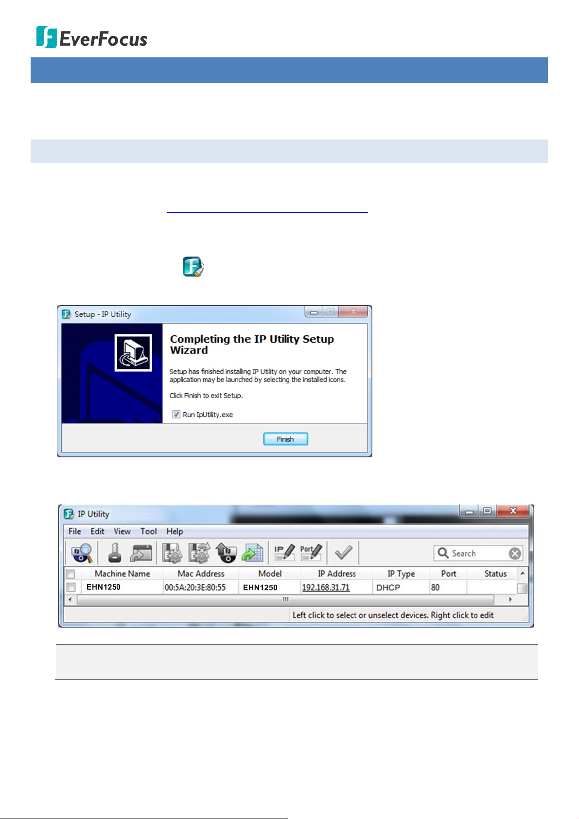
1. Save IP Utility Setup .exe in your computer. Double click the .exe file and follow the on-screen
instructions to install the IP Utility.
2. Click the Finish button, the IP Utility will be automatically launched to search the IP devices connected
on the same LAN.
Note: The default IP mode of the IP camera is DHCP. However, if there is no dynamic IP address
assigned to the device, its IP will switch to 192.168.0.10
10
Value IP Series Network Cameras – H265, 2MP / 5MP / 8MP
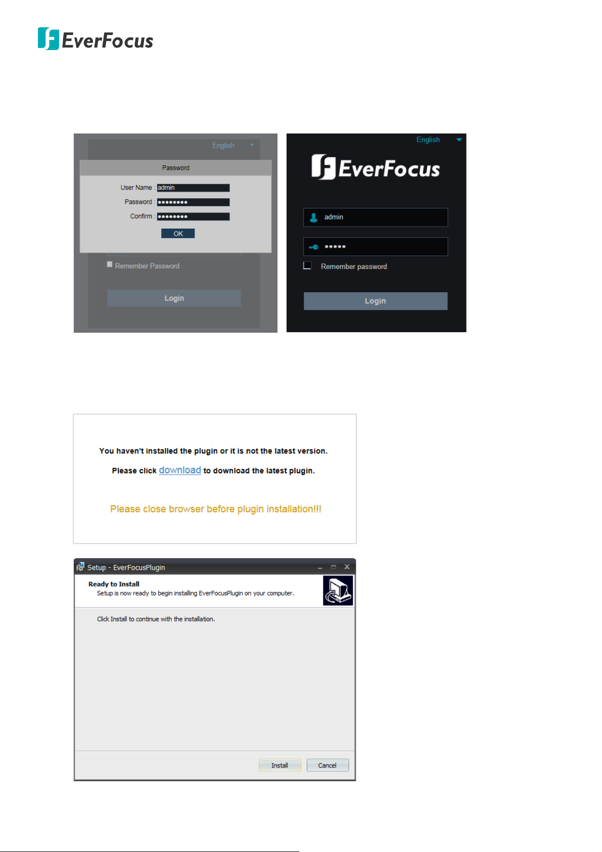
3. To access the Live View window, double click the IP address in the IP Address column, the Password
window pops up. By default, the ID is admin and there is no password. Please input a password for the
first-time login. Click the OK button, the Login window appears. Input the password and then click
Login, the Live View window appears.
Note for the first time login:
When the Plug-in block appears on the browser, click download to install the plug-in. Reload the
webpage and you should see the live view page now.
11
Value IP Series Network Cameras – H265, 2MP / 5MP / 8MP
4.2 Settings for Microsoft Internet Explorer
If you have difficulties viewing live view or upgrading firmware, it is suggested to complete the following
settings of your computer.
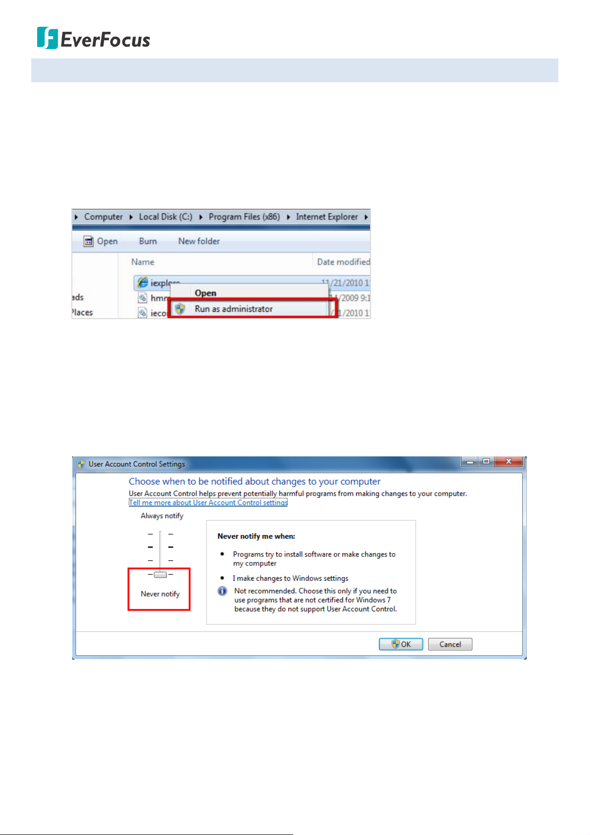
1. If your PC or laptop is running with Windows, it’s required to run the browser as administrator when
first entering the camera live view. Go to C:\Program Files (x86)\Internet Explorer, right-click the
browser and then click Run as administrator.
2. You may need to turn off the firewall and turn User Account Control off if you still can’t see the
camera Live View.
To turn User Account Control off, on the computer, click Start > Control Panel > System and
Security > Action Center (click Change User Account Control Settings), the User Account Control
Settings window appears. Adjust the slide bar to Never Notify and then click OK. Restart your
computer if requested.
12
Value IP Series Network Cameras – H265, 2MP / 5MP / 8MP
High-
speed modem
Internet
Straight-through LAN patch cable
Router
Cat
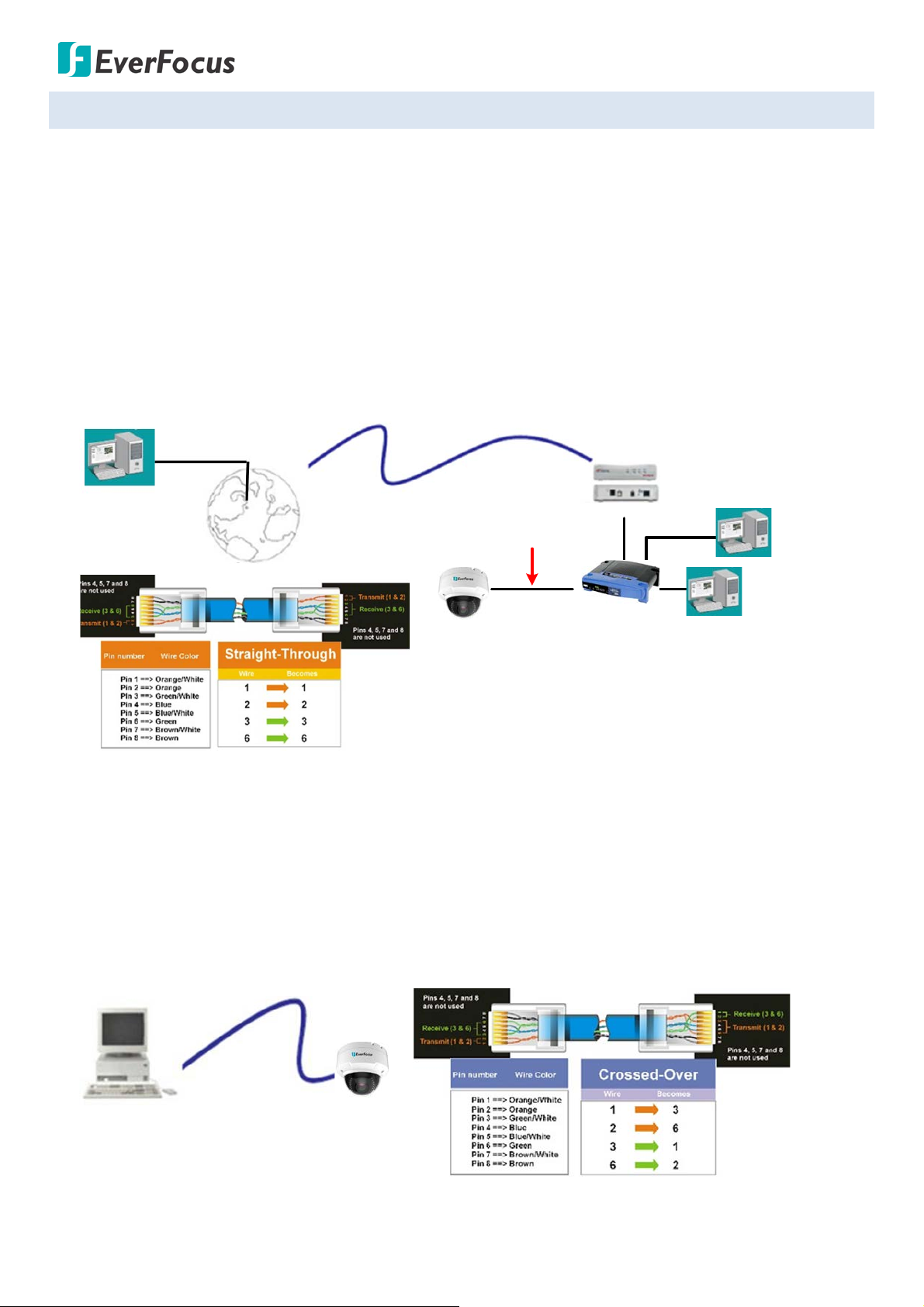
5 Straight Through Cable
Left: Pinout of a straight-through cable.
Cat 5
Right: Pinout of a crossed-over cable.
4.3 Connecting the Camera to the Network
There are three methods to connect the IP camera to the network: Router or LAN Connection,
One-to-One Connection and Direct High-Speed Connection.
Router or LAN connection
This is the most common connection in which the IP camera is connected to a router and allows multiple
users on and off site to see the IP camera on a LAN / WAN (Internet). The camera must be assigned an IP
address that is compatible with its LAN. By setting up port forwarding on the router, you can remotely
access the cameras from outside of the LAN via the Internet.
One-to-One Connection (Directly from PC to IP Camera)
You can connect directly without using a switch, router or modem. However, only the PC connected to
the camera will be able to view the IP camera. You will also have to manually assign a compatible IP
address to both the computer and the IP camera. Unless the PC has another network connection, the IP
camera will be the only network device visible to the PC. See the diagram below:
13
Value IP Series Network Cameras – H265, 2MP / 5MP / 8MP
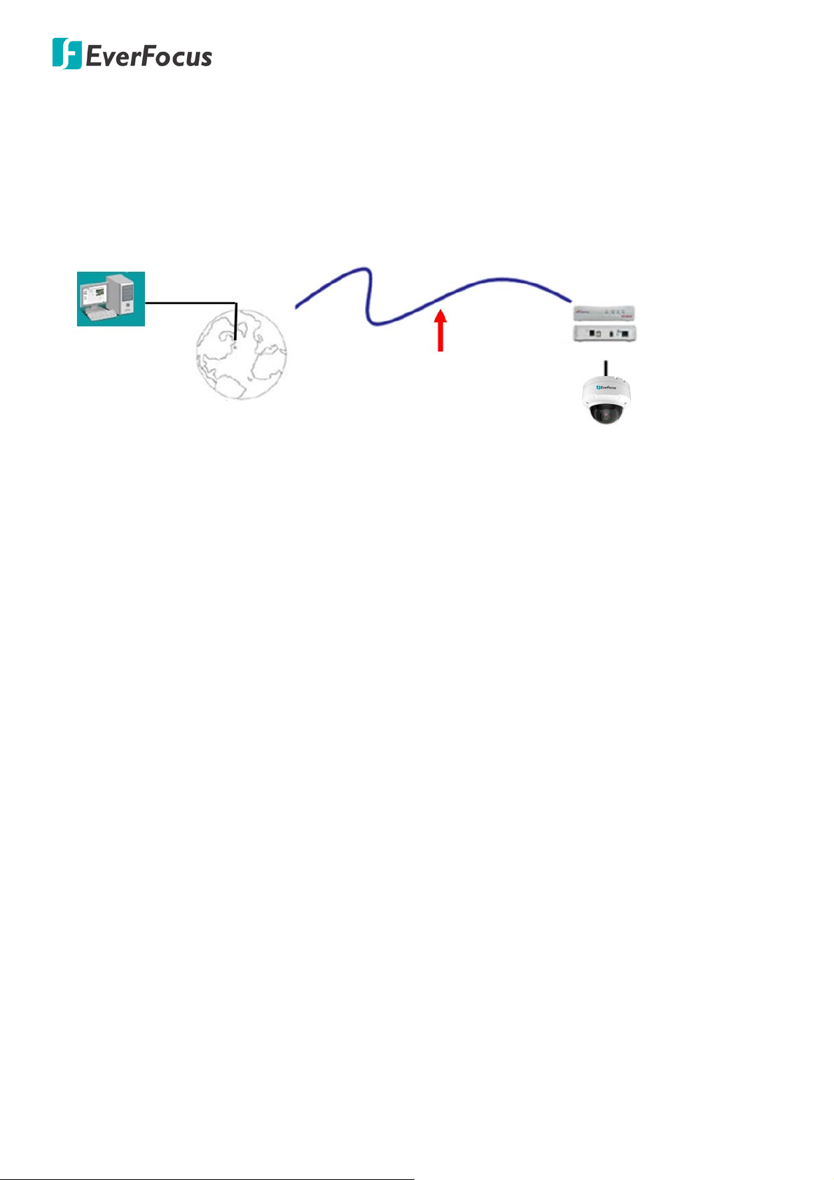
Cat 5
Straight Through Cable
High-speed modem
Internet
Direct High-Speed Connection
In a Direct High-Speed Connection, the camera connects directly to a modem without the need for a
router. You need to set the static or dynamic WAN IP address assigned by your ISP (Internet Service
Provider) in the camera’s configuration web pages. To access the camera, just type
“http://xxx.xxx.xxx.xxx”, where xxx.xxx.xxx.xxx is the IP address given by your ISP. If you have a dynamic
IP address, this connection may require that you use DDNS for a reliable connection.
14
Value IP Series Network Cameras – H265, 2MP / 5MP / 8MP
1
2
3
4
5
6
7
8
9
10
11
12
12
13
14
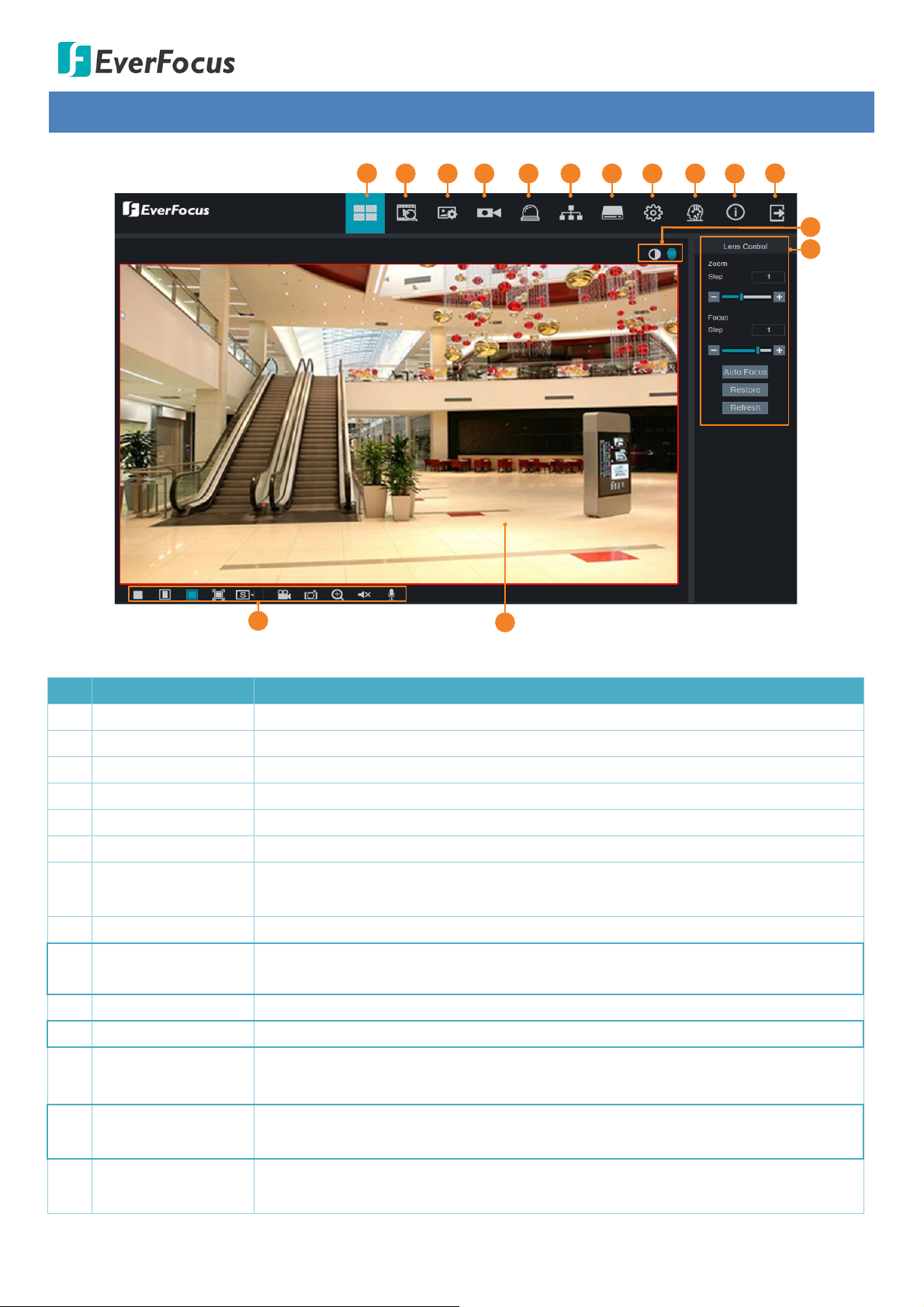
Displays the IP camera live view. You can double click on the Live View window
5 Live View Window
No. Name Description
1 Live Click to display the Live View window.
2 Playback Click to enter the Playback page. Please refer to 5.1 Playback.
3 Display Click to enter the Display setting page. Please refer to 5.2 Display Setting.
4 Record Click to enter the Record setting page. Please refer to 5.3 Record.
5 Alarm Click to enter the Alarm setting page. Please refer to 5.4 Alarm Setting.
6 Network Click to enter the Network setting page. Please refer to 5.5 Network Setting.
7 Storage
Click to enter the Storage Device setting page. Please refer to 5.6 Storage
Setting.
8 System Click to enter the System setting page. Please refer to 5.7 System Setting.
9 Intelligent
Click to enter the Intelligent setting page. Please refer to 5.8 Intelligent
Setting.
10 Login Info Move the mouse cursor over this icon to display the Login information.
11 Logout Click to logout the IP camera.
Color Setting /
12
Lens Control
Click the buttons to display the setup panel. Please refer to 5.9 Color Setting
and 5.10 Lens Control.
Live View Function
13
Icons
14 Live View Window
You can perform some functions on the Live View using these icons. Please
refer to 5.11 Live View Function Icons.
to full screen. Double click on the Live View can exit full screen.
15
Value IP Series Network Cameras – H265, 2MP / 5MP / 8MP
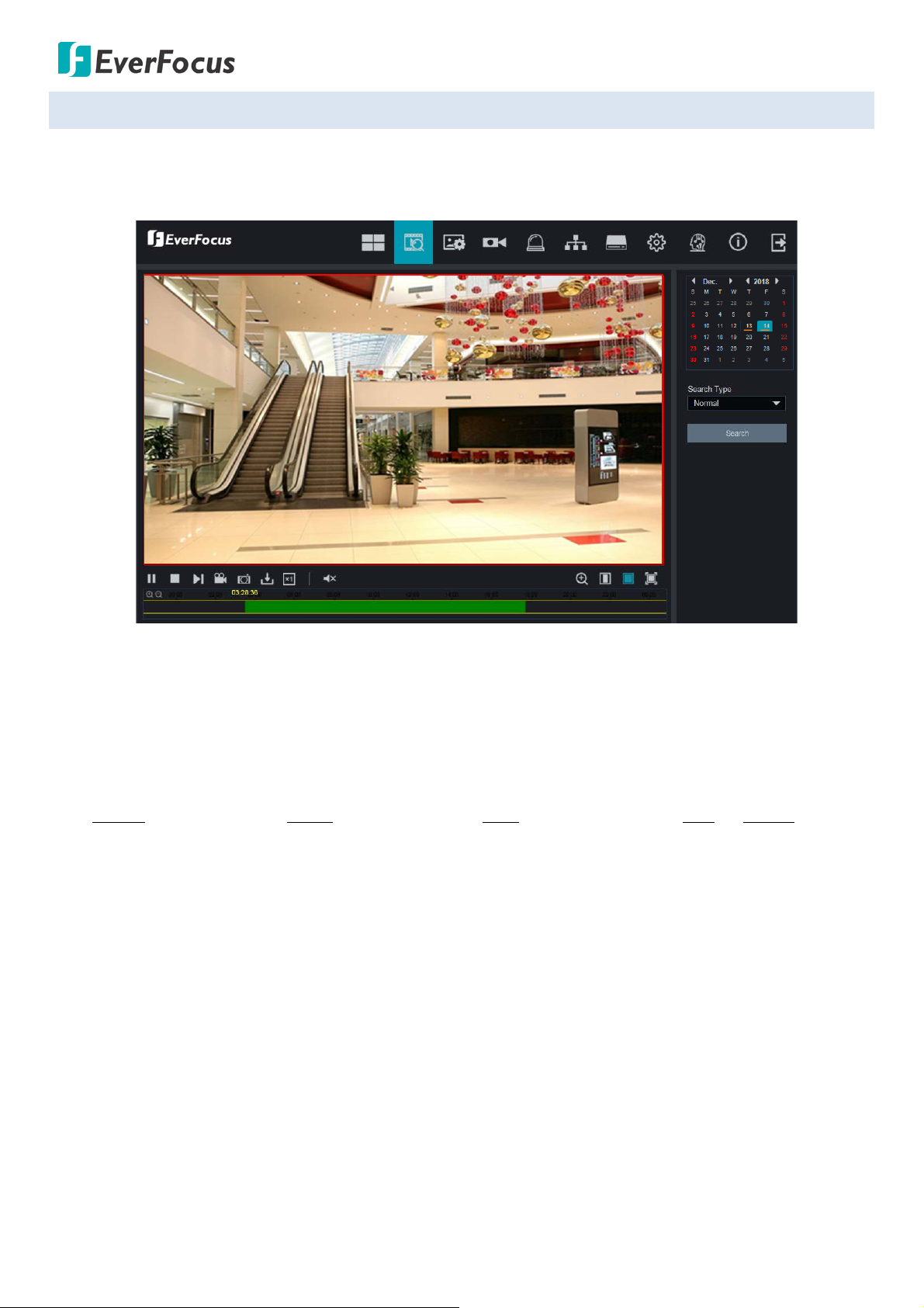
5.1 Playback
Click the Playback button on the top navigation bar. The Playback window displays. You can play back the
recordings stored in the on-camera micro SD card.
To st art playing back:
1. Select the date on the calendar (the date with an orange bar on the bottom indicates there are recordings
on the date).
2. Select the desired recording type(s) from the Search Type drop-down list.
3. Click the Search button, the recordings will be displayed on the time bar in different colors.
Green: Normal recordings; Yellow: Motion recordings; Blue: Intelligent recordings; Red: IO; Purple: Sound
Detection recordings.
4. Click the Play button to start playing back.
16
Value IP Series Network Cameras – H265, 2MP / 5MP / 8MP
00:00 02:00 06:
00 08
:00 10
:
00 12:00 14:00 16:00 18:00 20:00 22:
00 24:
00
1
2
3
4
5
6
7
8
9
10
11
12
13
14
Click to take a snapshot, a message window appears on the bottom-left
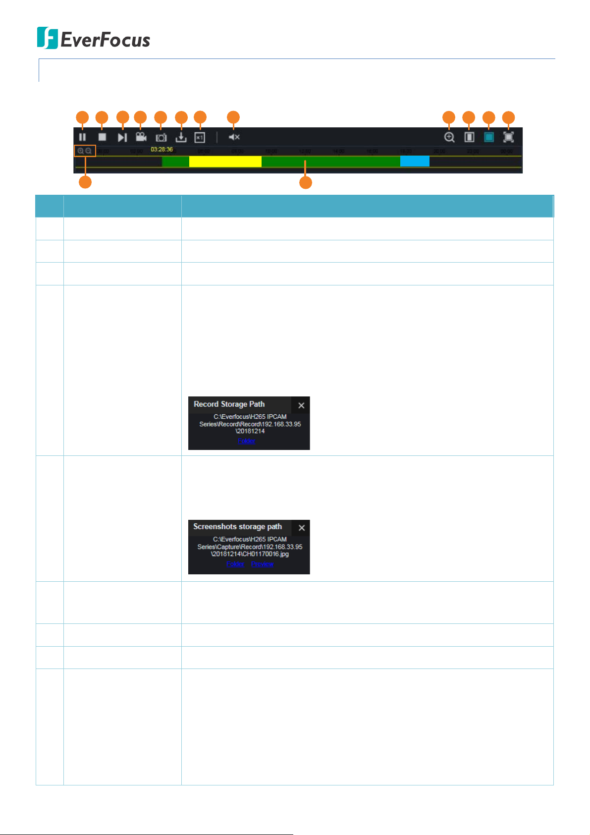
5.1.1 Playback Panel
You can use the Playback Panel to operate the below functions:
No. Name Description
1 Play/Pause Click to Play or Pause playing back.
2 Stop Click to Stop playing back.
3 Step Forward Click the button to play the recording frame by frame.
During the playback process, you can click the Video Clips button to start
recording from the clicked time, click the button again to stop recording, a
message window appears on the bottom-left corner of the screen. Click
Folder to open the folder to find the recording file. To change the manual
record storage path or the file format, please refer to 5.7.7 Local Settings.
4 Video Clips
You can use EverFocus Player or any player supporting the video format to
play back the recordings. EverFocus Player is included in the Software CD.
corner of the screen. Click Folder to open the folder to find the snapshot
image. Or click Preview to preview the snapshot image. To change the
storage path or image format, please refer to 5.7.7 Local Settings.
5 Snapshot
Click to download recordings. To perform the Download function, please
6 Download
refer to 5.1.2 Download.
7 Speed Click to select a playback speed.
8 Audio Click to switch on/off the speaker. You can also adjust the volume.
Click to enable the Digital Zoom mode. To exit the Digital Zoom mode, click
the button again. To perform the Digital Zoom function:
a. Click the Digital Zoom button to enable the function.
9 Digital Zoom
b. Use your mouse to draw an area where you want to have a close-up
view on the stream. The area will be zoom-in.
c. Right-click to exit the Digital Zoom mode.
17
Value IP Series Network Cameras – H265, 2MP / 5MP / 8MP
Click to display the Playback window in full screen mode. To exit full screen
10 Original Aspect Ratio Click to play back all the streams with original aspect ratio.
11 Stretch Click to stretch all the streams on the Playback window.
12 Full Screen
mode, press the ESC button on the keyboard or double-click on the screen.
13 Time Span Buttons You can adjust the time span on the Time Bar by clicking the buttons.
Single-click on the time bar at a certain time will start playing back from
the clicked time. The colors on the time bar represent different recording
14 Time Bar
types. Green: Normal recordings; Yellow : Motion recordings; Blue:
Intelligent recordings; Red: IO; Purple: Sound Detection recordings.
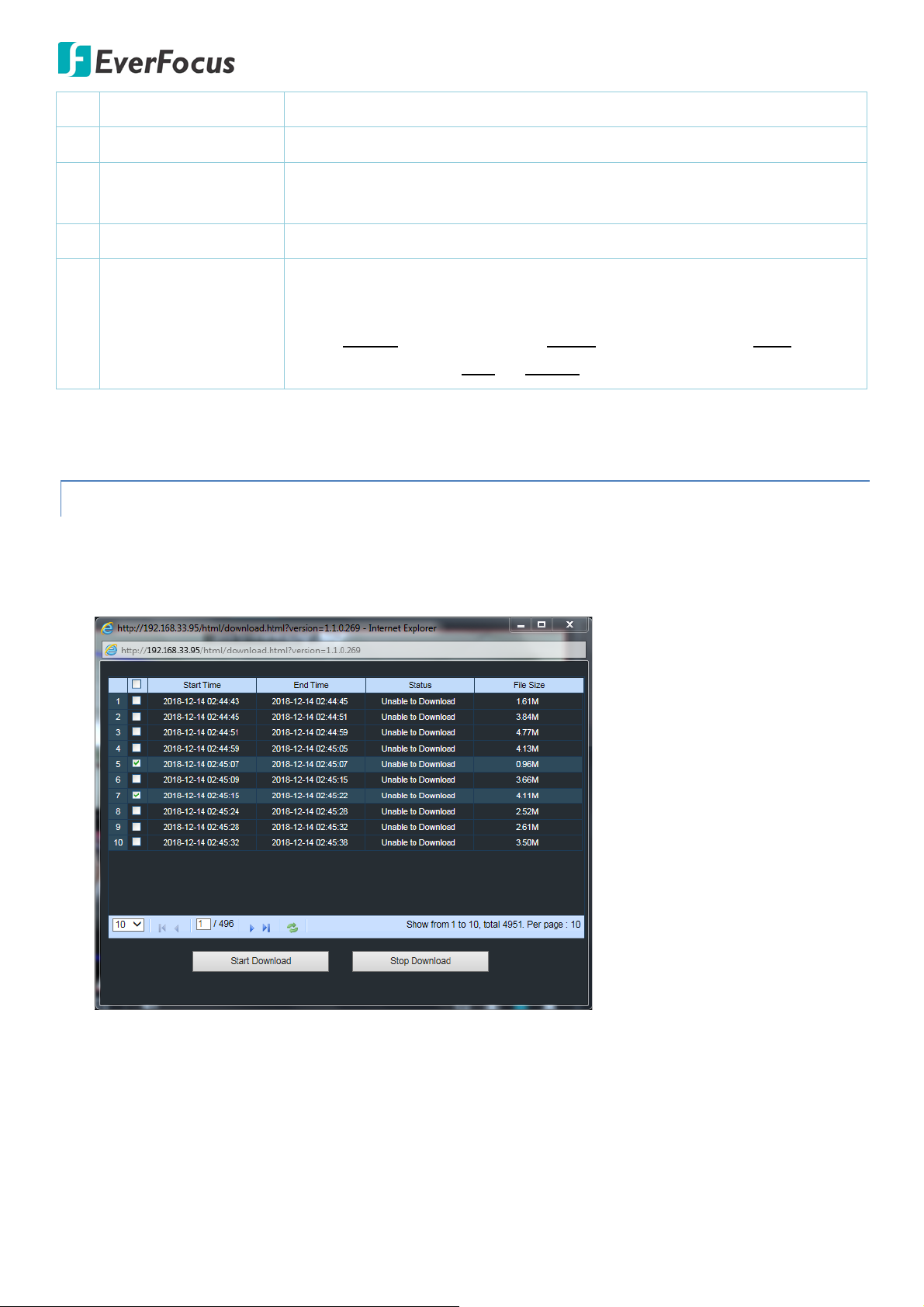
5.1.2 Download
You can download the recordings on the Playback window.
1. Click the Download button, the corresponding recordings will be displayed.
2. Select the desired recordings you want to download, and then click Start Download. To change the storage
path or the file format, please refer to 5.7.7 Local Settings.
18
 Loading...