

EverFocus EBC980R, EBC980M User Manual
Volume
1
User Manual
EBC980R
EBC980M
ID/Mifare Finger Vein Single-Door Controller

EverFocus Electronics Corporation
EBC980R
EBC980M
Instruction Guide
2015 EverFocus Electronics Corp
All rights reserved. No part of the cont#s of this manual may be reproduced or transmitted in any form or by any means
without written permission of the EverFocus Electronics Corporation.

Read This First
Read this instruction guide before you install or operate your EverAccess product.
Note: Use this product only for the purpose for which it was designed. Product
specifications might be subject to change without prior notice.
Safety Warning
This product is designed for indoor use only. Do not expose the product to high
humidity and dust.
Temperature: this product is designed to operate in the temperature range -10°C ~
50°C / 14°F ~ 122°F
Cleanse: Power off the product before cleansing. Do not use liquid cleaners or aerosol
cleaners. Use a damp cloth to clean it.
Maintenance: Do not spill liquid of any kind onto the product. It may erode the
components and cause short-circuiting.
Service: Do not attempt to service the product by yourself. Opening or removing
covers may expose you to dangerous voltage or other electric hazards. Contact our
technical support for any service or repair needs. Unauthorized opening or tampering
of the product may void the warranty.

Table of Content
1 Introduction ....................................................................................................... 1
1.1 EBC980 Series Models ......................................................................................... 1
1.2 Features ............................................................................................................... 2
1.3 Packing List .......................................................................................................... 2
1.4 Specification ........................................................................................................ 3
1.5 Physical Diagram ................................................................................................. 4
2 Installation Overview ......................................................................................... 5
2.1 Stand-Alone System Cording Diagram ................................................................ 5
2.2 Terminal Definition .............................................................................................. 6
2.3 Preparing for Installation ..................................................................................... 7
2.3.1 Obtain a Floor Plan ....................................................................................... 7
2.3.2 Determining Hardware and Location ........................................................... 8
2.3.3 Determine the Number of Finger Vein Controller According to the System
Structure .................................................................................................................... 8
2.4 Mounting Finger Vein Controller......................................................................... 9
2.5 Connecting ........................................................................................................ 10
2.5.1 Connecting of Power Supply ....................................................................... 10
2.5.2 Connection with the Output of the Alarm ................................................. 11
2.5.3 Connection with Alarm Detector Input ...................................................... 11
2.5.4 Connection with Door Lock ........................................................................ 11
2.5.5 Connection with Request-to-Exit Button .................................................... 12
2.5.6 Connection with Door Sensor ..................................................................... 12
2.6 Connecting Finger Vein Controller and Computer ............................................ 13
2.6.1 Connection with Computer via TCP/IP Interface ........................................ 13
2.7 Reset Controller ................................................................................................. 13
2.8 Before the First Use ........................................................................................... 14
2.9 Tips to Capture a Finger Vein ............................................................................ 14
2.9.1 Insert Your Finger into the Finger Vein Reader Terminal ........................... 14
2.9.2 Hold Finger for a Few Seconds ................................................................... 14
2.10 Routine Maintenance..................................................................................... 14
3 Operating Instructions of Finger Vein Controller ............................................... 15
3.1 Operating Instruction ........................................................................................ 15
3.2 Enter System Setting ......................................................................................... 15
3.3 Enter Menu Setting After Verification ............................................................... 16
3.4 Setting of First Grade Menu .............................................................................. 17
3.5 System Setting ................................................................................................... 18
3.5.1 Set Language ............................................................................................... 19
3.5.2 Set Date Format .......................................................................................... 19
3.5.3 Set Date ...................................................................................................... 20
3.5.4 Set Time ...................................................................................................... 20
3.5.5 Set Daylight Saving Time ............................................................................ 21
3.5.6 Set System Password .................................................................................. 21
i

3.5.7 Set ARM Password ...................................................................................... 22
3.5.8 Restore Expired Event ................................................................................. 23
3.5.9 Erase All Events ........................................................................................... 23
3.5.10 Restore Factory Setting ........................................................................... 24
3.6 Card Setting ....................................................................................................... 25
3.6.1 Add Cards .................................................................................................... 25
3.6.2 Delete Cards ................................................................................................ 26
3.6.3 Set Card Properties ......................................................................................27
3.6.4 Synchronize Vein Data In the “Card Setting” menu, scroll to “Synchronize
Vein Data” menu item and press “#” to synchronize the vein data......................... 31
3.7 Door Setting....................................................................................................... 32
3.7.1 Set Open Time ............................................................................................ 32
3.7.2 Set Over Time ............................................................................................. 33
3.7.3 Door Access Mode ...................................................................................... 33
3.7.4 Set Timeout Time ....................................................................................... 34
3.7.5 Set Direction ............................................................................................... 34
3.8 Alarm Setting ..................................................................................................... 34
3.8.1 Composition of Alarm ................................................................................. 34
3.8.2 Basic Configuration of the Alarm ................................................................ 35
3.8.3 Enter Alarm Setting Menu .......................................................................... 35
3.8.4 AlarmIN Setting ........................................................................................... 35
3.8.4.1 Fire Alarm Setting. ........................................................................................37
3.9 Address Setting .................................................................................................. 38
3.10 Set Network ................................................................................................... 39
3.10.1 DHCP Setting ........................................................................................... 39
3.10.2 Set IP Address .......................................................................................... 39
3.10.3 Reset Network ......................................................................................... 40
3.11 System Information ........................................................................................ 40
3.12 System Operation Description ....................................................................... 40
3.12.1 Single Card Access Mode ......................................................................... 40
3.12.2 Single PIN Access Mode .......................................................................... 41
3.12.3 Finger Vein + PIN Mode ........................................................................... 41
3.12.4 Multi-Card Access Mode ......................................................................... 42
3.12.5 Specific Door Access Mode ..................................................................... 42
4 Software Introduction ...................................................................................... 43
4.1 Main Functions .................................................................................................. 43
4.2 Profiles of Highlighted Features ........................................................................ 43
5 Getting Started ................................................................................................. 44
5.1 Quick Start ......................................................................................................... 44
5.1.1 Set Department and Cardholder ................................................................ 44
5.1.2 Set Access Rule ........................................................................................... 45
5.1.3 Multiple Card Addition Methods ................................................................ 46
5.1.4 Export Function ...........................................................................................47
5.1.5 Print Function ............................................................................................. 48
ii

5.2 First Use ............................................................................................................. 49
5.2.1 Login Page ................................................................................................... 49
5.3 Get Familiar with the Browser Page .................................................................. 50
5.3.1 Introduction of the Main Page.................................................................... 50
5.3.2 Menu ........................................................................................................... 51
5.3.3 Control Panel .............................................................................................. 51
5.3.4 System Event Record .................................................................................. 52
6 Basic Setting ..................................................................................................... 54
6.1 Change Password .............................................................................................. 54
6.2 Set User and Authority ...................................................................................... 55
6.3 User Group .........................................................................................................57
6.3.1 Add User Group ...........................................................................................57
6.3.2 Change User Group ......................................................................................57
6.3.3 Delete User Group .......................................................................................57
6.4 User Setting ....................................................................................................... 58
6.4.1 Add User ..................................................................................................... 58
6.4.2 Edit User ..................................................................................................... 59
6.4.3 Delete User ................................................................................................. 59
6.4.4 Export User Information ............................................................................. 60
6.4.5 Print User Information ................................................................................ 60
6.4.6 Search User ................................................................................................. 60
6.5 Local Server ....................................................................................................... 60
6.6 System Upgrade ................................................................................................. 61
6.6.1 Online Upgrade ........................................................................................... 62
6.6.2 Local Upgrade ............................................................................................. 62
6.7 Reboot Controller .............................................................................................. 62
7 Cardholder ....................................................................................................... 63
7.1 Department Setting ........................................................................................... 63
7.1.1 Add Department ......................................................................................... 64
7.1.2 Edit Department ......................................................................................... 64
7.1.3 Delete Department ..................................................................................... 64
7.2 Cardholder Setting ............................................................................................ 65
7.2.1 Add Cardholder ........................................................................................... 66
7.2.2 Change Cardholder ..................................................................................... 69
7.2.3 Delete Cardholder ...................................................................................... 69
7.2.4 Export Cardholder Information .................................................................. 70
7.2.5 Print Cardholder Information ..................................................................... 70
7.2.6 Query Cardholder ....................................................................................... 70
7.3 Import Cardholders ........................................................................................... 70
8 Real-time Monitoring ....................................................................................... 72
8.1 Real-Time Event ................................................................................................ 72
8.2 Report ................................................................................................................ 73
8.2.1 Query Cardholder Information ................................................................... 73
8.2.2 Export Cardholder Information .................................................................. 73
iii

8.2.3 Print Cardholder Information ..................................................................... 73
9 Maintenance .................................................................................................... 74
9.1 Data Backup ........................................................................................................74
9.1.1 Manual Backup ............................................................................................74
9.1.2 Automatic Backup ....................................................................................... 75
9.1.3 Exception Backup ........................................................................................ 75
9.2 Restore ................................................................................................................76
9.2.1 Restore from FTP .........................................................................................76
9.2.2 Restore from Local .......................................................................................76
9.3 Purge Out-of-date Data ..................................................................................... 77
10 Controller Management ................................................................................ 78
10.1 Controller Setting ........................................................................................... 78
10.1.1 Normal Setting ........................................................................................ 78
10.1.2 Alarm Input .............................................................................................. 79
10.1.3 Alarm Setting ........................................................................................... 80
11 Access Rule ................................................................................................... 81
11.1 Date Type ....................................................................................................... 81
11.1.1 Add Date .................................................................................................. 81
11.1.2 Delete Date .............................................................................................. 82
11.2 Door Schedule ................................................................................................ 83
11.3 Group Schedule .............................................................................................. 84
11.3.1 Add Group Schedule ................................................................................ 85
11.3.2 Delete Group Schedule ............................................................................ 85
11.3.3 Set Group Schedule ................................................................................. 86
11.3.4 Save the New Schdule ............................................................................. 87
11.4 Access Group .................................................................................................. 87
11.4.1 Add Access Group .................................................................................... 87
11.4.2 Delete Access Group................................................................................ 88
12 Card Management......................................................................................... 89
12.1 Card Setting .................................................................................................... 89
12.1.1 Add (Register) Card .................................................................................. 90
12.1.2 Edit/Change Card ..................................................................................... 91
12.1.3 Change Cards in Batch ............................................................................. 92
12.1.4 Delete Card .............................................................................................. 92
12.1.5 Delete All Cards ....................................................................................... 92
12.1.6 Export Card Information .......................................................................... 92
12.1.7 Print Card Information ............................................................................ 92
12.1.8 Query Card .............................................................................................. 92
12.2 Card Import .................................................................................................... 93
13 Report........................................................................................................... 94
13.1 Card Report .................................................................................................... 94
13.1.1 Query Card Information .......................................................................... 94
13.1.2 Export Card Information .......................................................................... 94
13.1.3 Print Card Information ............................................................................ 95
iv

13.2 Card-dependent Event ................................................................................... 95
13.2.1 Query Card-Related Events...................................................................... 95
13.2.2 Import Card-Related Events .................................................................... 95
13.2.3 Print Card-Related Events ........................................................................ 95
13.3 Card-independent Event ................................................................................ 96
13.3.1 Query Card-Irrelevant Events .................................................................. 96
13.3.2 Import Card-Irrelevant Events ................................................................. 96
13.3.3 Print Card-Irrelevant Events .................................................................... 96
14 Basic Attendance Management ..................................................................... 97
14.1 Attendence Time Setting ............................................................................... 97
14.2 Edit Attendence Time .................................................................................... 97
14.2.1 Query Attendance Time .......................................................................... 98
14.2.2 Export Attendance Information .............................................................. 98
14.2.3 Print Attendance Information ................................................................. 98
14.3 Week Holiday Setting ..................................................................................... 98
14.3.1 Edit Weekend .......................................................................................... 99
14.3.2 Query Weekend ....................................................................................... 99
14.3.3 Export Weekend ...................................................................................... 99
14.3.4 Print Weekend ......................................................................................... 99
14.4 Special Holiday Setting ................................................................................. 100
14.4.1 Add Special Date .................................................................................... 100
14.4.2 Query Special Holiday Setting ............................................................... 100
14.4.3 Edit Special Date .................................................................................... 101
14.4.4 Delete Special Date ............................................................................... 101
14.4.5 Export Special Date ............................................................................... 101
14.4.6 Print Special Date .................................................................................. 101
15 Attendance Exception ................................................................................. 102
15.1 No-Access-Attendance ................................................................................. 102
15.1.1 Add No-Access-Attendance ................................................................... 102
15.1.2 Query of Registration of Not Swiping a Card ........................................ 103
15.1.3 Edit Record of Not Swiping a Card ......................................................... 103
15.1.4 Delete Registration of Not Swiping a card ............................................. 103
15.1.5 Export Registration of Not Swiping a card ............................................. 104
15.1.6 Print Registration of Not Swiping a card ............................................... 104
15.2 Time-off Enroll ............................................................................................. 104
15.2.1 Add Time-off Enroll ............................................................................... 104
15.2.2 Query Time-off Enroll ............................................................................ 105
15.2.3 Edit Time-off Enroll ............................................................................... 105
15.2.4 Delete Leave Record .............................................................................. 106
15.2.5 Export Time-off Enroll ........................................................................... 106
15.2.6 Print Time-off Enroll .............................................................................. 106
15.3 Overtime Enroll ............................................................................................ 106
15.3.1 Add Overtime Enroll .............................................................................. 106
15.3.2 Query Overtime Enroll ........................................................................... 107
v

15.3.3 Edit Overtime Enroll .............................................................................. 107
15.3.4 Delete Overtime Enroll Records ............................................................ 108
15.3.5 Export Overtime Enroll Records. ........................................................... 108
15.3.6 Print Overtime Enroll Record. ................................................................ 108
16 Attendance Report ...................................................................................... 109
16.1 Original Access Record ................................................................................. 109
16.1.1 Query Original Access Record ............................................................... 109
16.1.2 Export Original Access Record ............................................................... 109
16.1.3 Print Original Access Record .................................................................. 109
16.2 Report by Cardholder ................................................................................... 110
16.2.1 Generate Report by Cardholder ............................................................ 110
16.2.2 Export Report by Cardholder ................................................................ 110
16.2.3 Print Report by Cardholder ................................................................... 110
16.3 Statistics by Cardholder ............................................................................... 111
16.3.1 Generate Statistics by Cardholders ....................................................... 111
16.3.2 Export Statistics by Cardholders ............................................................ 111
16.3.3 Print Statistics by Cardholder ................................................................ 111
16.4 Statistics by Department .............................................................................. 111
16.4.1 Generate Statistics by Department ....................................................... 112
16.4.2 Export Statistics by Department ............................................................ 112
16.4.3 Print Statistics by Department .............................................................. 112
vi
EBC980R / 980M
Chapter
1
1 Introduction
The EBC980 Series is a standalone Linux-based IP access control system combined with a
finger vein reader, card reader and a door controller. The series comes in two models:
EBC980R and EBC980M. You can simply connect the system to the door using a Cat 5
cable and connect the system to power through the PoE port. Built-in with a finger
vein and an RFID module, the system can provide up to 13 door-open patterns
including Finger vein, Finger vein + PIN, Finger vein or PIN, Normal Close, Always
Unlocked, etc. Users can manage the access or events through the Web browser easily.
1.1 EBC980 Series Models
EBC980R: Supports ID card
EBC980M: Supports MIFARE card
1

1.2 Features
Note: Contact the shipper if any items appear to have been damaged in the shipping
• Web-based; cross-network and cross-area management through WAN and
Internet
• High security; Use encryption with random code to save finger characteristics
• SSL ensures safe sessions over the web browsers
• DHCP and Static IP supported; plug and play
• Multiple languages supported (ex. Chinese, English, Russian)
• Online upgrade functions
• Can access 6,000 users with 2 finger vein template per user
• 1,000,000 log entries; identification time: 1 : 2000 ≦1.5sec
• FAR < 0.0000067%; support group number up to 2048
• 10 intervals per day with 1 minute minimum per intervel
• Provide 3 types of programmable dates with up to 255 types of date
configurations
• Support real-time eMap dispalying and editing
• Support real-time event logging
• User friendly design: opertate easily with the keyboard
• OLED display and keyboard
• Powerful management functions; manage based on time, dates, locations, card
holder license, etc.
• Powerful alarm functions; remove / add area alarms; easy to connect the
corresponding door while fire alarm alerted
1.3 Packing List
Please check that there is no missing item in the package before installing.
EBC980 Series Finger Vein Controller x 1
Hex Screw Driver x 1
Self-Tapping Screw x 4 (for installing the device)
Nickel-Plated Machine Screw x 4 (for installing the device)
Expansion Screw x 4 (for installing the device)
User’s Manual x 1
process. If any items are missing, notify your EverFocus Electronics Corp. Sales
Representative or Customer Service Branch. Please also keep the shipping carton for
possible future use.
2

1.4 Specification
Web-Based
Support setting, monitoring and management
Database
Sqlite3
Processor
32-bit RISC CPU, 200/250MHz
Storage
512MNAND Flash, 64MDDR SDRAM
Finger Vein Capacity
Max. log entry
1,000,000
Identification method
1:1 / 1:N
Identification speed
1:1:≤1 sec, 1:2000:≤1.5 sec
FAR
0.0000067% (1/1,500,000)
FRR
0.01% (1/1,000,000)
FETR
Door Control
Single Door
Card-Reading Distance
5 ~ 12cm
Card-Reading Time
200ms
Keypad
3×4
2×8 (for Chinese characters)
Alarm Input
1 fire alarm, 1 general alarm
Alarm Output
1 alarm output
Management Group
2048 groups
Programmable Duration
10 per day (minimum: 1 minute)
Programmable Date
3 date types, up to 255 date types
Door-Open Type
13 types
Multiple Cards
Supported
Card Password
8 digits
System Password
8 digits
Arm / Disarm Password
8 digits
Card Expiration
Yes
Daylight Saving Time
Yes
Power-Fail Protection
Yes
Real-Time Clock
Yes
Anti-Dismantle Switch
Yes, N C
Max. Current
5A (for door control relay) / 2A (for alarm relay)
Power Consumption
< 10W
Power Supply
DC12V±15%, 1A / PoE
Dimensions (H×W×D)
180 × 140 × 87mm / 71 x 58 x 35 inch
Operating Temperature
-10°C ~ 50°C / 14°F ~ 122°F
Relative Humidity
20% ~ 80% (no condensation)
Frequency
OLED Display Screen
<
<
<0.03%
RFID card: 125KHz;Mifare card: 13.56MHz
2×16 (for English / Russian characters)
3
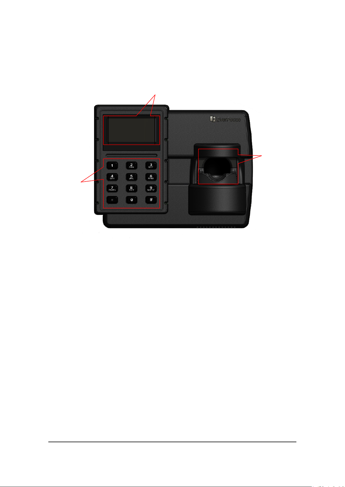
1.5 Physical Diagram
2014-10-03
Finger Vein
3×4 Keypad
The physical diagram of EverFocus EBC980 Series is illustrated as below.
2×8 OLED Display
THU 09:38
Welcome!
Reader
Figure 1.1 Finger Vein Physical Diagram
(1) Finger Vein Detector
Features AutoON function, which can automatically detect finger vein.
(2) OLED Display Screen
OLED Display Screen displays the status and menu of this controller.
(3) Keypad
For configuring the settings, inputing PIN code and some basic operations.
4

2 Installation Overview
Chapter
2
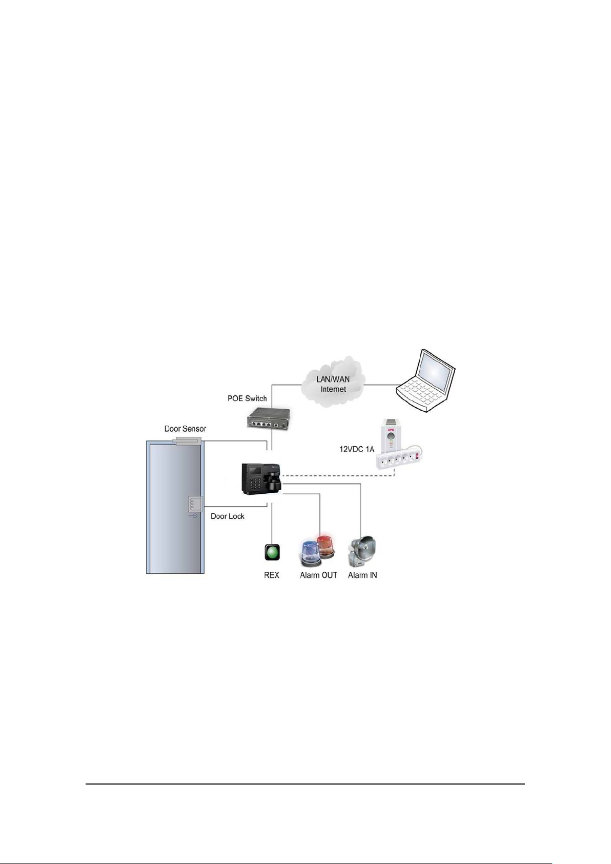
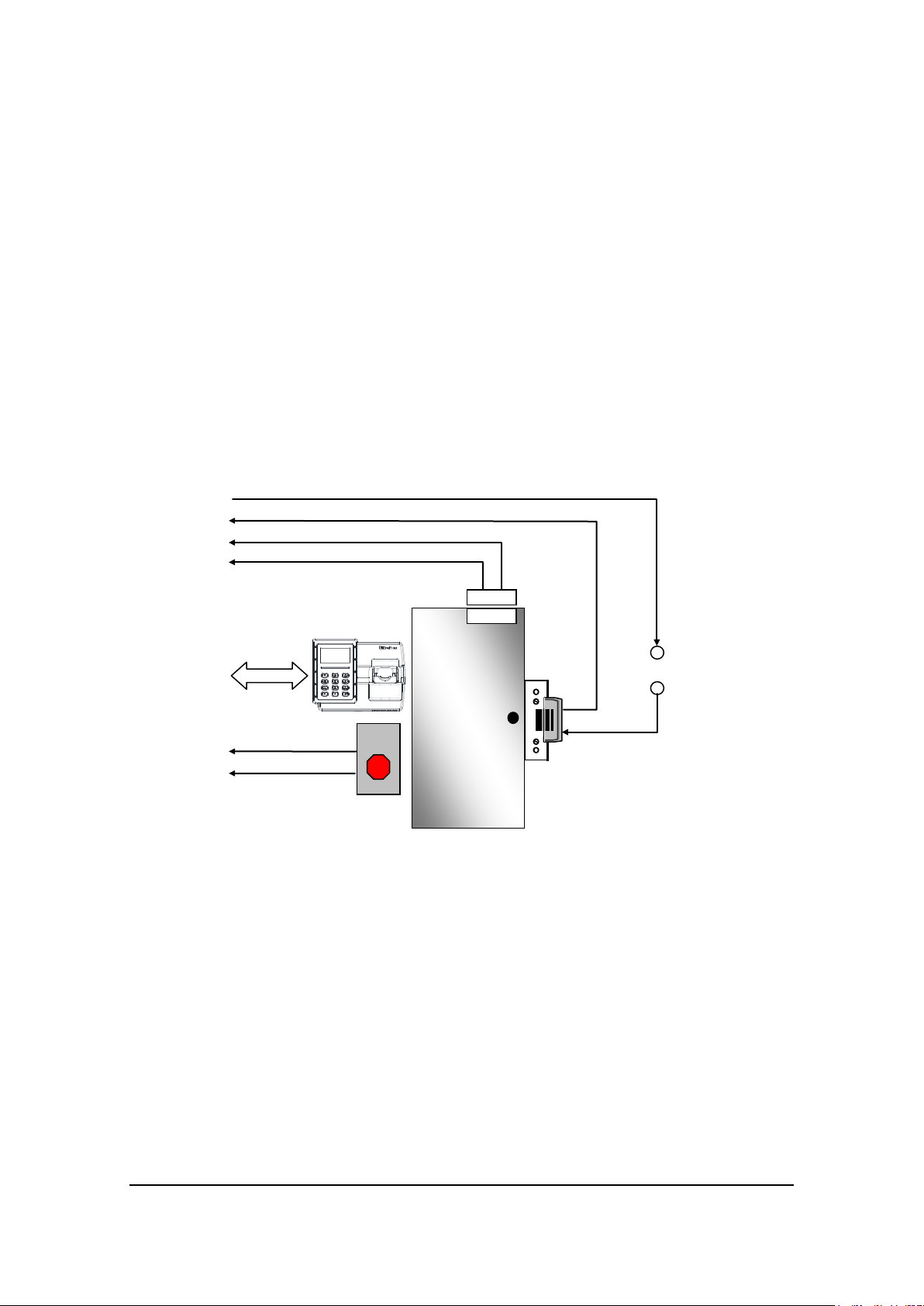
Client visit the built-in access control system
Alarm
Alarm
Door-open
Door
Door-lock
After preparation, the user can start installing. In this part, we mainly introduce the
installing of hardware.
2.1 Stand-Alone System Cording Diagram
Input
management software through browser
Output
button
sensor
5
output
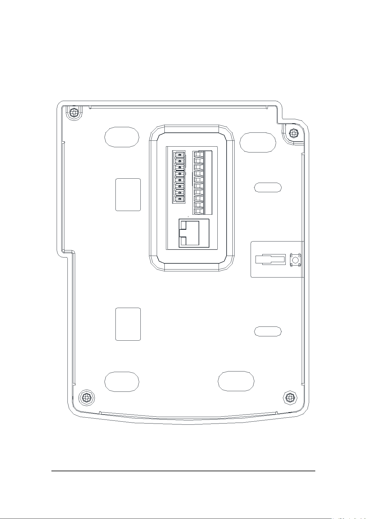
2.2 Terminal Definition
1
2 3 4
5 6 7 8
9
10 11
12 1
3 14
15 16
17 1
8
There are 18 connecting terminals in the finger vein controller, it is illustrated in
Figure2.1:
Figure 2.1 Terminals on the Rear Panel
6

The definitions of the terminals are listed in the following table:
Alarm Relay Normally
Alarm Relay Common
Alarm Relay Normally
Door Relay Normally
Door Relay Common
Door Relay Normally
8
GND
Ground
18
GND
Ground
Tamper Relay
Tamper Relay
Table 2.1 Terminal Definition
No. Category Function No. Category Function
1 Finre Alm IN Fire Alarm Input 11 AlarmNO
2 GND Ground 12 AlarmCOM
3 AlarmIN Alarm Input 13 AlarmNC
4 GND Ground 14 DoorNO
5 DoorButton Door-Open Button 15 DoorCOM
6 GND Ground 16 DoorNC
7 DoorSensor Door Sensor Input 17 12VDC +12VDC Input
9 TamperSwitchNO
10 TamperSwitchCOM
Normally Open
Output
Common Output
Open Output
Output
Closed Output
Open Output
Output
Closed Output
2.3 Preparing for Installation
Before beginning the installation, it is recommended that the user gather certain
information to better prepare. Proper preparation will help ensure a smooth
installation, and will save the installer time and reduce unnecessary efforts. The
following information is essential for a professional installation.
2.3.1 Obtain a Floor Plan
Obtain a floor plan of the building in which the access control system is to be installed.
Obtaining a floor plan helps the installer determine what components need to be
installed, and where. It also is essential in determining the length of cable needed to
connect readers to the controller. A floor plan can be a blue print of the building, a
design, or simply a drawing of the facility. Any document showing the footprint of the
building can be used. The dimensions are important to note, especially when
determining cable lengths. A floor plan may be obtained from your local city hall.
7
2.3.2 Determining Hardware and Location
EBC980
Door Sensor
Door Lock
Additional
Power Su
Button
V+
V-
Determining which hardware to use and where it will be installed.
Determining which hardware to use and where it will be installed. This is the most
crucial step in the preparation stage. First, determine how many access points, or
doors, need to be managed by the access control system. These access points will
control the security of the facility, and can limit the entry and exit to and from any
given area of the building. After deciding which doors need to be controlled, the user
must also determine the level of security needed at the door. There are many ways to
manage the door, using different resources. These resources include, but are not
limited to: finger vein controllers, magnetic lock, relays, and door-open button. The
equipments of door-open button include door-open sensor or button, which should be
installed onto the safer side of the door.
pply
Figure 2.2 Common Door Configuration with Finger Vein Controller
2.3.3 Determine the Number of Finger Vein Controller According to the System
Structure
Determine how many finger vein controllers are needed
1. Each EBC980 series controller can control one door. If the system to be
installed requires more than one door, additional controllers are necessary.
These controllers can be connected to a single access control system.
2. If one or more controller is to be installed at a different location within a
single access control system, EverFocus’ Access Control Management
Software is required to be installed for management.
8
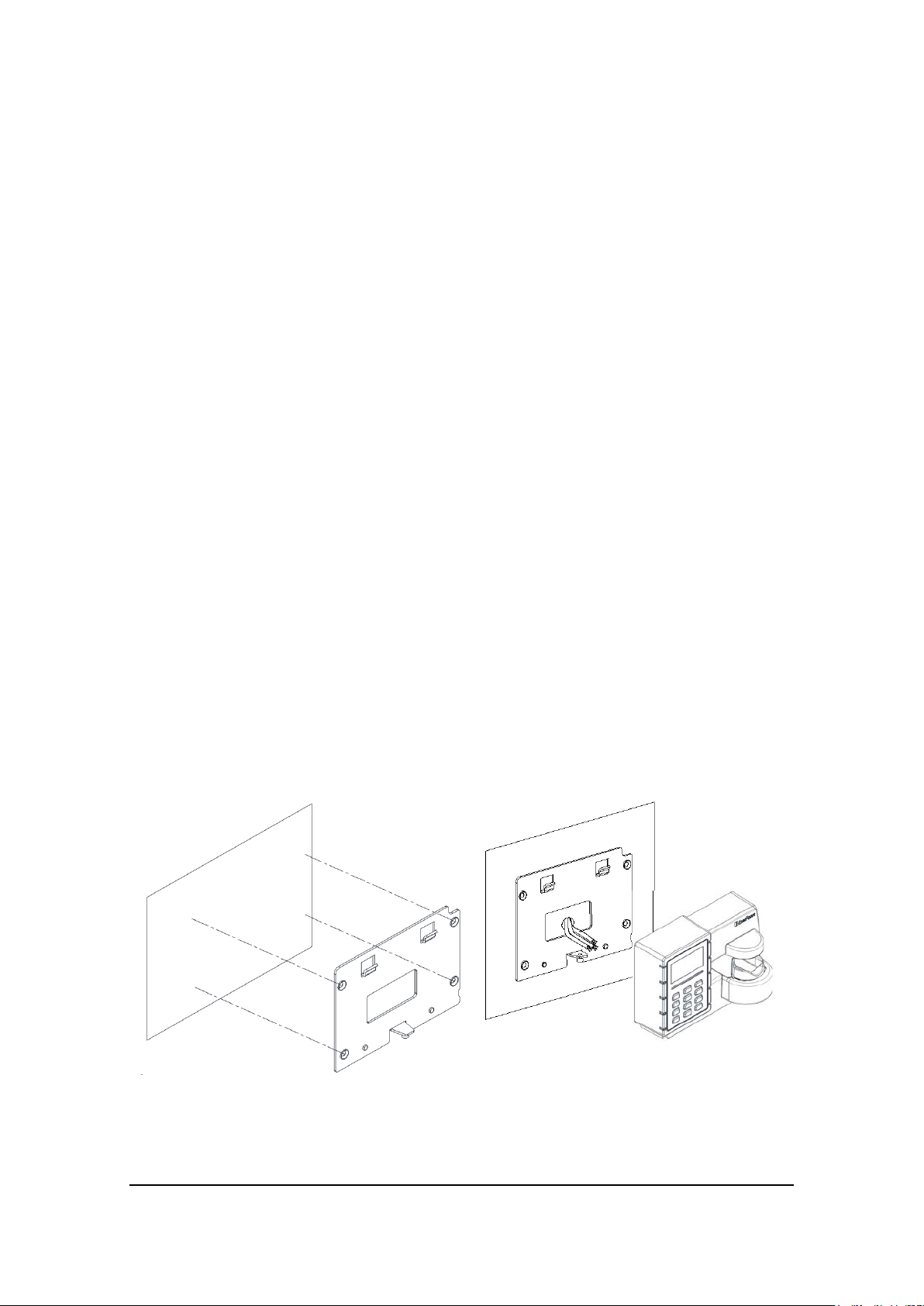
2.4 Mounting Finger Vein Controller
1: Terminal Area
2-5: Latches
1
2
3
4
5
Step 1
Step 2
The finger vein controller has a built-in reader working as an entry reader, so it should
be installed close to the door where it guides. As a common rule, the finger vein
controller should not be installed on a metal, which will lower the card sense range.
The finger vein controller package contains a supporting frame to elevate the
controller in order to make wire connections more convenient. The installation is
described in the steps below:
Step 1: Mount the supporting frame on to the wall.
Use the four anchor screws (provided in the package) to mount the frame to the wall.
Step 2: Make cable hole
In the terminal area, marked as 1 in step 1 of the figure, make a hole on the wall, big
enough to allow all the wires go through. Note the wiring diagram will be addressed in
the following sections. Wire all the required cables before step 3.
Step 3: Mount the finger vein controller to the supporting frame
Align the finger vein controller to the 4 latches (marked as 2 to 5 in step 1 figure) on
the frame, and attach the controller to the frame (marked as 1 in step 2 figure). Make
sure the latches are in position. Then push down the controller a little bit to lock the
position (marked as 2 in step 2 figure).
Step 4: Lock the screw at bottom
Secure the controller to the base board by tiding the screws at bottom of controller
(exclusive screw driver is provided in the controller package).
Note: the screw has to be fastening to push down (secure) the tamper switch.
9
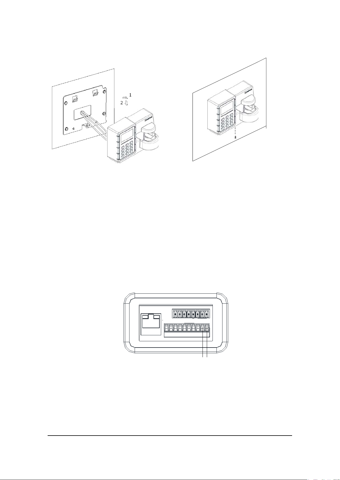
Step 3 Step 4
Figure 2.3 Mount Finger Vein Controller
Figure 2.4 Connecting of Power Supply
1 2 3 4 5 6 7
8
9 1011 12 13 14 15 16 17 18
V+ V-
2.5 Connecting
2.5.1 Connecting of Power Supply
The finger vein controller can be power-supplied through specific POE network switch.
Normal connecting of the finger vein controller and the switchboard with reticle can
realize the power supply to the finger vein controller.
EBC980 series finger vein controller can also be power-supplied by connecting the
binding post on the rear panel. Rear panel terminal No. 17 and 18 are respectively the
positive pole and negative pole of the power source of the finger vein controller, it is
illustrated as Figure 2.4.
The voltage range of power source of EBC980 series finger vein controller is DC
12V±15%, and the current is not less than 1.5A. The distance between the power
supply and the finger vein controller should be less than 2 meters.
10
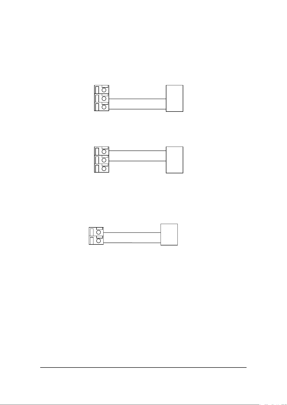
!Important The magnetic lock, panalarm and the finger vein controller should be
AlarmOut
COM
NC
11
13
Alarm
Figure 2.5 Connection with Normally Closed Circuit Alarm
AlarmOut
11
13
Alarm
Figure 2.6 Connection with Normally Open Circuit Alarm
NO
COM
AlarmIN
AlarmIn
GND
3
4
Alarm
Detector
Figure 2.7 Connection with Alarm Dectector Input
powered respectively.
2.5.2 Connection with the Output of the Alarm
a. Connection with normally closed circuit alarm.
12
b. Connection with normally open circuit alarm.
12
2.5.3 Connection with Alarm Detector Input
The connection with alarm detector input
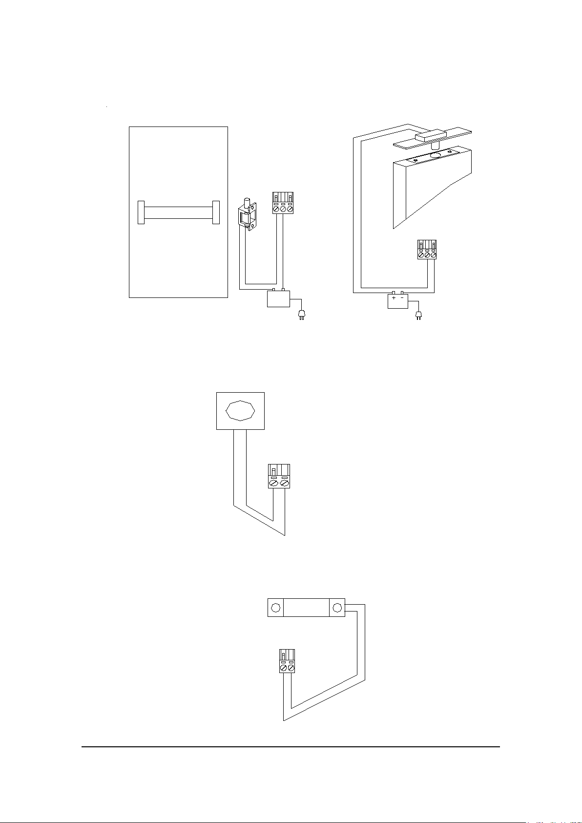
2.5.4 Connection with Door Lock
The electric lock should be power supplied independently and the power source of the
lock should be decided according to the demand of the electric lock. Select the cable
for the lock prudently so that it can fit the needs of the electric current. There are two
kinds of regularly used electric controlled lock: power-on door-open and power-off
door-open, the methods of connecting differs, just as illustrated in figures below.
11
DoorSENSOR
7
Figure 2.11 Connection with Door Magnetic Detector
Figure 2.8 Power-on Door-open
Figure 2.9 Power-off Door-open
DoorNO
DoorCOM
14
16
14
DoorNO
Power-on Door-open
Power-off Door-open
DoorBUTTON
Figure 2.10 Connection with Door-open Button
E X IT
5
DoorNC
15
2.5.5 Connection with Request-to-Exit Button
GND
6
DoorCOM
DoorNC
15
16
2.5.6 Connection with Door Sensor
12
GND
8
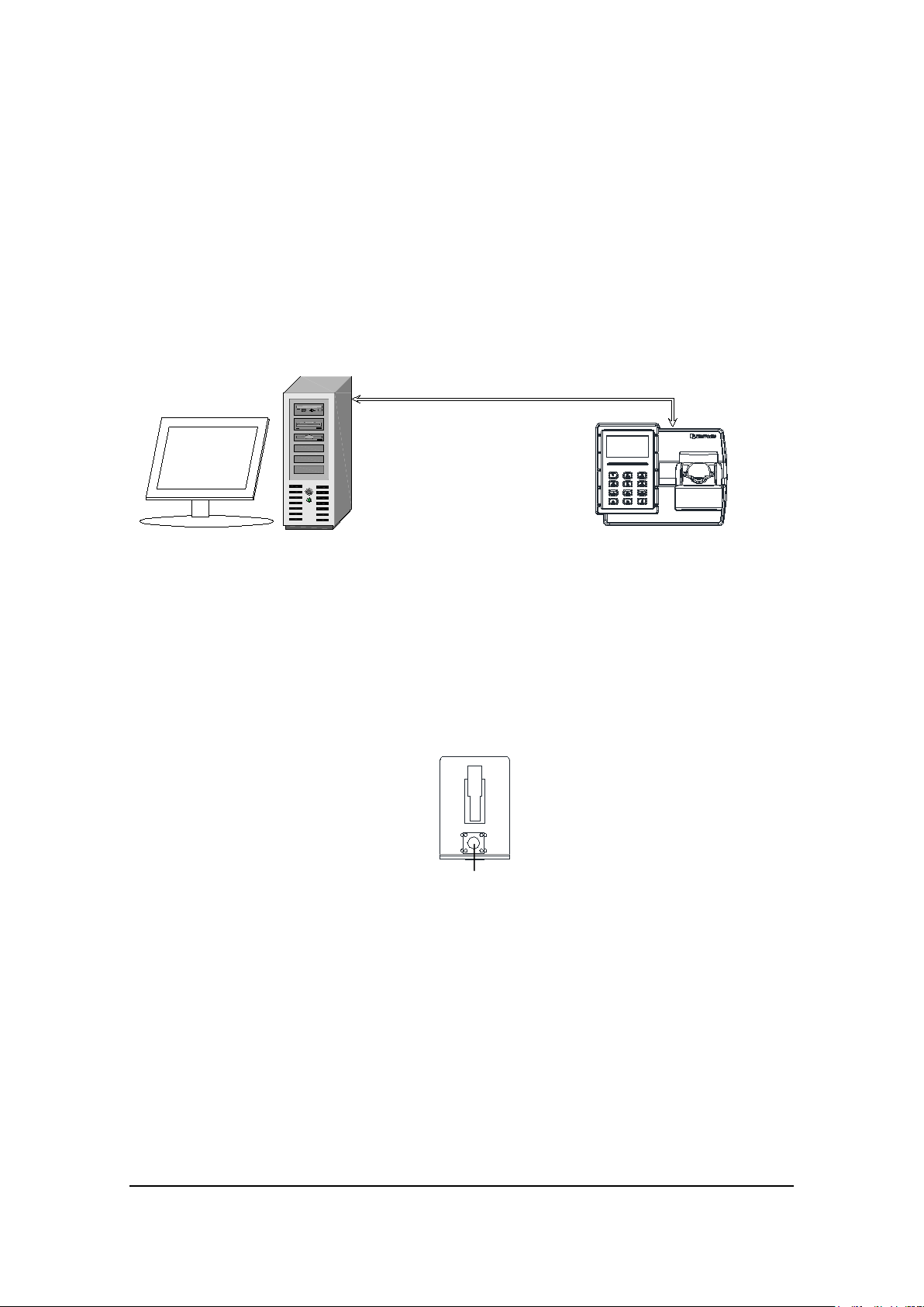
2.6 Connecting Finger Vein Controller and Computer
Reset
TCP/IP
2.6.1 Connection with Computer via TCP/IP Interface
EverFocus EBC980 series finger vein controller can work independently, EBC980 has
built-in server, and users can visit the built-in management system page directly
through any computer. EBC980 can also work with computer on-line via TCP/ IP and
work as common controller among EverFocus series access control software. Access
control software can conduct all the setting and management to it.
Figure 2.12 Connection of Finger Vein Controller with Computer
2.7 Reset Controller
Before powering on the finger vein controller, reconfirm that all wires are connected
correctly. If you want to restore to factory settings, press on the reset switch and power
on until the system of the finger vein controller starts up.
Figure 2.13 Reset Switch
!Important Resetting the finger vein controller will completely remove the
users' information, event records and all systematic settings in the controller. The
operation is unrecoverable, please proceed with caution.
13

2.8 Before the First Use
Before the first use, please set as the following steps:
1. Set the address, date and time of the finger vein controller
2. Setting of alarm signal
3. Setting of door
4. Set IP address
2.9 Tips to Capture a Finger Vein
2.9.1 Insert Your Finger into the Finger Vein Reader Terminal
Insert a finger into the deep end of the finger vein reader terminal (the finger vein
reader allows 0 to 45 degrees of finger rotation).
2.9.2 Hold Finger for a Few Seconds
When the machine is processing, please hold the finger for a couple of seconds until
the message appears on the OLED display or the buzzer sounds.
2.10 Routine Maintenance
Oil stain, food residues and other stains will not affect the regular collecting of the
controller. The finger vein controller is designed exclusively for industry and it can work
in relatively hostile environment, for example, over cold or over heated.
Please clean the surface of the finger vein scanner regularly:
Wipe the controller and the surface of the finger vein scanner with dry or wet
clothe or soft paper towel. Apply glass cleaner with PH6~8 can remove some dirt if
necessary.
Please avoid using cleaner with PH < 4.5. It might damage the controller and
plastic part.
Do NOT pour cleaner or any other liquid on the controller surface or machine. It
causes power shortage.
14

Chapter
3
2015-02-26
3 Operating Instructions of Finger Vein Controller
The controller can set all the hardware function through the buttons on the operating panel.
Date, time interval and access Access Ruless should be set in the embedded webpage of the
finger vein controller. Details are displayed in the following instruction manual of the
software.
3.1 Operating Instruction
The 4*4 keypad of the finger vein controller is located under the OLED display. “#” is the
system set key, “*” is arm and disarm key. In menu screen, “2” and “8” turn pages of
different menus in the same grade. Press “5” and “#” to enter the submenu. Press “*” to
enter the previous menu.
3.2 Enter System Setting
After the finger vein controller functions properly, the OLED display will show the current
date and time, on the second line on the display, it is rolling display of “Welcome!” which
can be changed to other words on the webpage (up to 40 English characters and 20 Chinese
characters), and this interface is called the home screen which provides corresponding
display of each operation of the controller. After entering the system, each time when you
press “*” will quit the current menu operation and return to the previous menu. In addition,
keep pressing key “*” or no operation for one minute, the system will automatically return
to home screen.
MON 09:38
Welcome!
15

In normal condition, if you press key “#”, the system will require the user to input the
Please place admin
2015-02-26
SYS Password
system managing password.
_ _ _ _ _ _ _ _
Cancel OK
!Important The factory default password is 00000000. In order to secure the controller,
change the password after the first login and keep the password in a safe place.
After inputting the password, press key “#” to confirm. In case that wrong passwords are
input for three times, the system will lock the keypad automatically for one minute. Pressing
the keypad again, the display will show “Keypad is Locked!”, and the keys don't work at the
time.
MON 09:38
Keypad is Locked!
Welcome!
3.3 Enter Menu Setting After Verification
Input the right system password, press “#”. If there is no administrator in the system, enter
system menu directly after inputting the right password; if there is administrator, verify the
administrator first, the display of the controller shows as the following Figure:
finger……
_________
At the moment, you can sweep the administrator's card or input the ID of administrator or
press in the administrator’s finger vein, when the administrator inserts his/her finger, it
shows:
16

Card Setting
System Setting
Door Setting
Authentication failed
Please place admin
Verifying admin…
Please wait…
In case the card or ID number hasn't been registered with the finger vein in the system,
enter the system setting menu directly after sweeping the card or inputting ID number;
otherwise, the display shows the following information after sweeping the card or inputting
ID number:
finger……
In case the finger vein or user’s right is wrong, the following information is displayed and
the system will return to the main interface.
3.4 Setting of First Grade Menu
After entering the system, the display shows the first grade menu, select the items using key
“2” and “8”. The first grade menu is shown as the following figure:
System Setting Menu
Card Setting Menu
Door Setting Menu
17
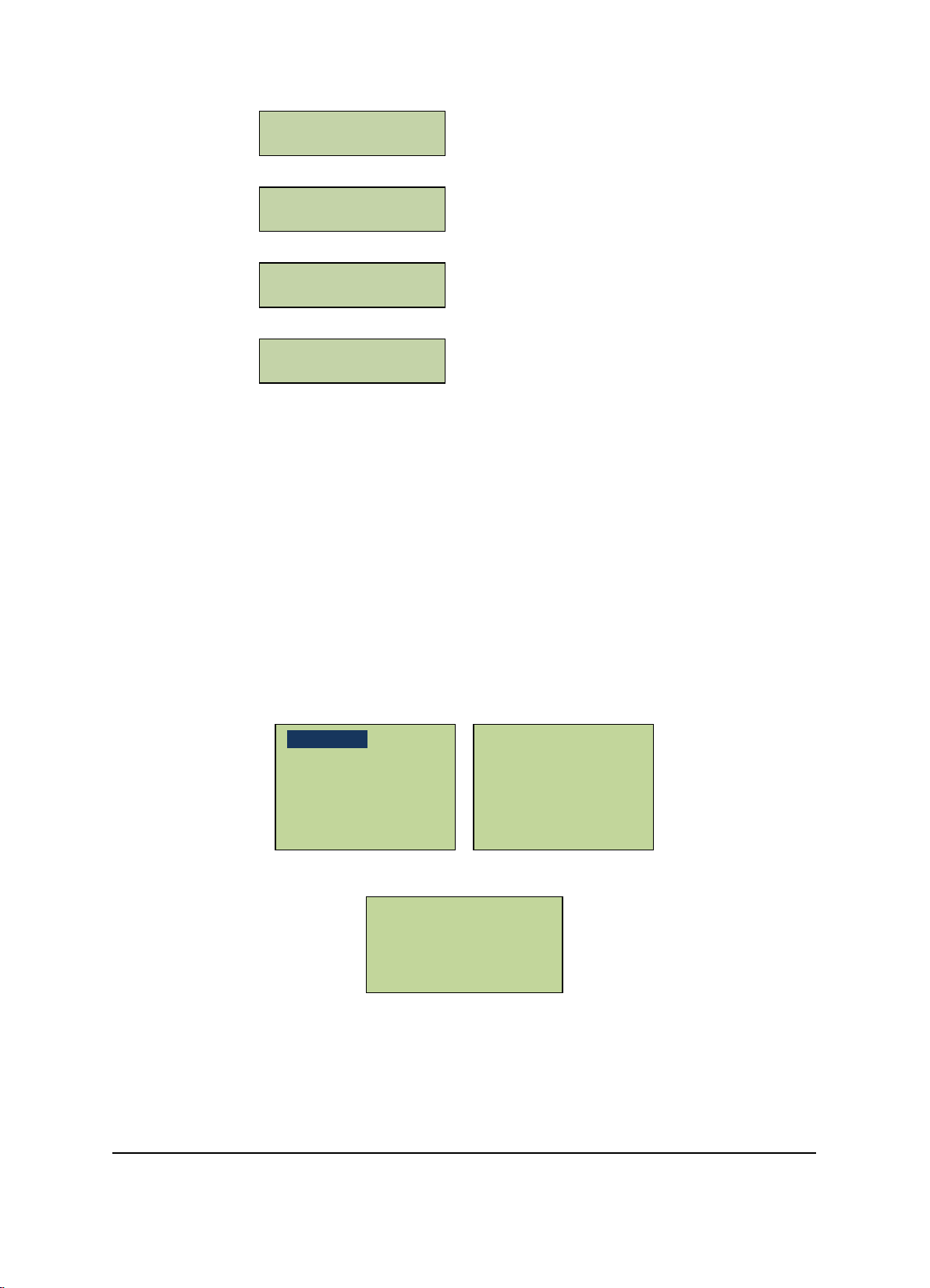
Alarm Setting Menu
Erase All Events
Auto Daylight Saving
Set Language
System Information
Set Network
Address Setting
Alarm Setting
Address Setting Menu
Network Setting Menu
System Information Menu
Press “#” to enter correspond menu to set items.
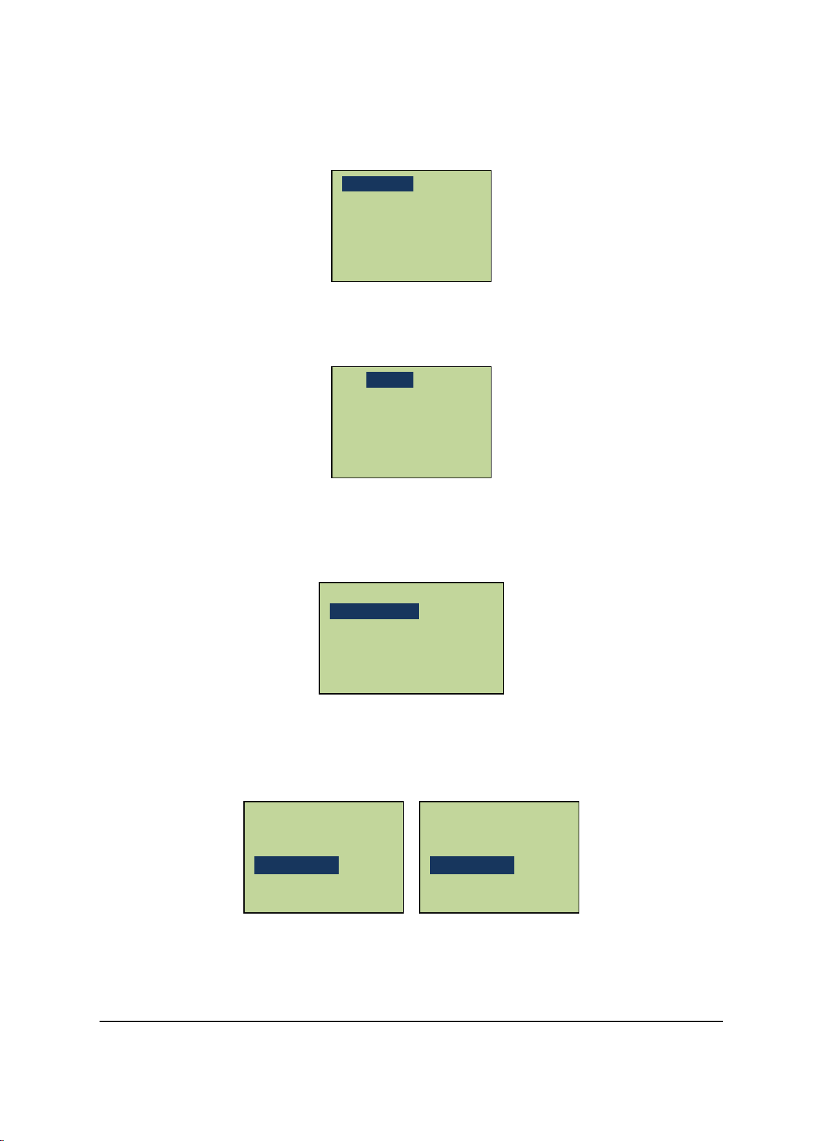
3.5 System Setting
In the System Setting main menu, scroll to “System Setting” menu item and press “#” to
enter the “System Setting” menu. In the System Setting menu, there are 10 submenu items
in all. Users can carry out basic setup by selecting the corresponding menu items, such as
date, time, password, etc. After entering the “System Setting” menu, the following screen
will show up:
Roll up and down with the numerical keys 2 and 8 to select the menu items and press “#” to
enter the corresponding setup.
Set Date Format
Set Date
Set Time
Set SYS Password
Set ARM Password
Restore Expired Event
Restore Factory
18
3.5.1 Set Language
Set Language
*English
Set Language
In the “System Setting” menu, scroll to “Set Language” menu item and press “#” to enter
the “Set Language” interfaces.
Set Date Format
Set Date
Set Time
Scroll to select Chinese, English or Russian, press “5” to select, press “#” to save setting and
exit and press “*” to cancel the setting.
简体中文
Russian
3.5.2 Set Date Format
In the “System Setting” menu, scroll to “Set Date Format” menu item and press “#” to enter
the “Set Date Format” interface.
Set Date Format
Set Date
Set Time
Users can select two date formats: “MM-DD-YY” or “YY-MM-DD.” The current date format is
displayed on OLED screen. Press “#” to toggle between the two formats. Press “*” to exit
the data display format setup interface. And return to the “System Setting” menu.
YYYY-MM-DD
[#]to toggle
MM-DD-YYYY
[#]to toggle
19

3.5.3 Set Date
Set Time
Set Language
Date (YYMMDD)
Set Language
In the “System Setting” menu, scroll to “Set Date” menu item and press “#” to enter the
“Set Date” interface.
Set Date Format
Set Date
Set Time
Use the numerical keys to input the current date with 6 digits (YY: MM: DD).The year is set
in the range of 2000-2038. Press “#” to confirm the change to the new date.
20__-__-__
Cancel OK
3.5.4 Set Time
In the “System Setting” menu, scroll to the “Set Time” menu item and press “#” to enter the
“Set Time” interface.
Set Date Format
Set Date
Set Time
Use the numerical keys to input the current time with 6 digits (HH:MM:SS). The time is set
in the range of 00:00:00--23:59:59. After input is finished, press “#” to confirm.
__:__:__
Cancel OK
20
3.5.5 Set Daylight Saving Time
Set Date
Daylight Saving
Daylight Saving
Set Date Format
In the “System Setting” menu, scroll to “Auto Daylight” menu item and press “#” to enter
the “Auto Daylight Saving” interface.
Set Date
Set Time
Auto Daylight Saving
Press “#” to toggle between summer time on Yes/No and press “*” to exit. The setting is
finalized upon exit.
ON [#] to toggle
No
[#]to toggle
ON [#] to toggle
Yes
[#]to toggle
When the summer time setting is enabled, the controller will automatically adjust to the
summer time, i.e. the a.m. 1:59:59 of the first Sunday in April is adjusted to a.m. 3:00, and
the a.m. 1:59:59 of the first Sunday in October is adjusted to a.m. 1:00:00.
3.5.6 Set System Password
The user is requested to input the system administration password before setting the
controller. The default password of the system is 00000000. For security purposes, it is
suggested that the user changes the password before using the controller and properly
secure the password. Once the password is lost, the system administration password has to
be reset after general reset, meanwhile, the data in the system will be deleted.
In the “System Setting” menu, scroll to the “Set SYS Password” menu and press “#” to enter
the “Set SYS Password” interface.
Set Time
Auto Daylight Saving
Set SYS Password
21
 Loading...