

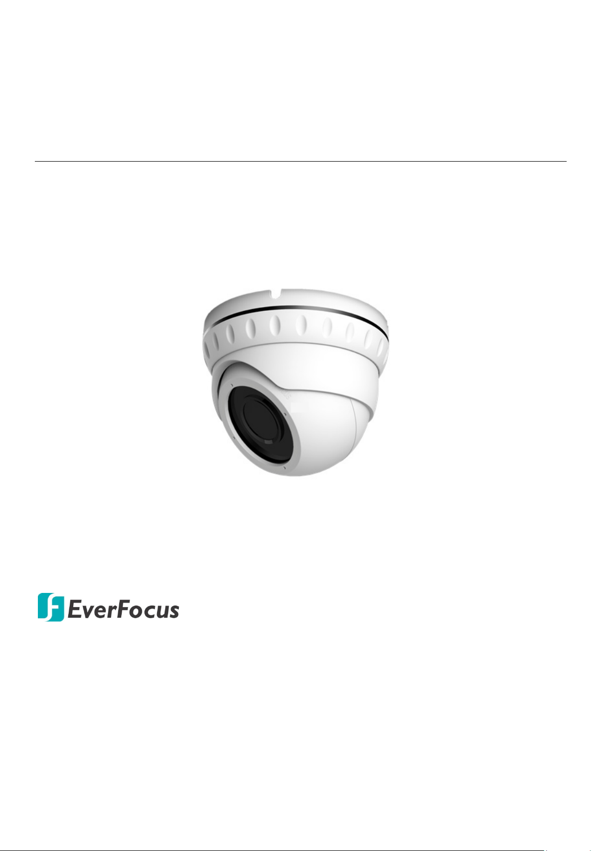
EBA2880 eZ.HD Series
8MP, IP66 IR Dome Camera
User’s Manual
Copyright © EverFocus Electronics Corp.
Release Date: May, 2019
All the images including product pictures or screen shots in this document are for example
only. The images may vary depending on the product and software version. Information
contained in this document is subject to change without notice.
EverFocus Taiwan:
2F., No.12, Ln. 270, Sec. 3, Beishen Rd., Shenkeng Dist., New Taipei City 222, Taiwan
TEL: +886 2 2662 2338 FAX: +886 2 2662 3632 www.everfocus.com.tw

Camera x 1
Screw & Screw Anchor x 4
98mm
/
3
.
86
"
120mm /
4.72"
60
.2
mm / 2
.37"
1. Introduction
EverFocus eZ.HD series cameras – EBA2880 deliver 8MP image quality. The
model is equipped with CMOS sensor and provides motorized 3.6-11mm lens
with ICR. Featured with True Wide Dynamic Range (T-WDR), the camera can
provide clear images even under backlight circumstances where intensity of
illumination can vary excessively. The EBA2880 supports both NTSC and PAL
scanning systems (auto detection) and is IP66 certified.
1.1 Packing List
Mounting Sticker x 1
L-Type Wrench x 1
User Manual x 1
1.2 Features
Equipped with 8MP CMOS sensor
Motorized 3.6-11mm lens with ICR to capture the desired field of view
Extended IR range of up to 30m / 98ft. with 24 LEDs (depends on scene
IR reflectivity)
T-WDR to improve the visibility under high contrast scene
The flexible angle viewing with its 3-Axis rotation design allows wall or
ceiling mounting
IP66-rated with metal housing
Supports UTC function: Control camera OSD settings from DVR end
1.3 Dimensions
1
2
E320
EB45
12VDC
Power Cable
Video Output Cable
(BNC,
75Ohm)
Outer Housing
Camera Base
Camera Body
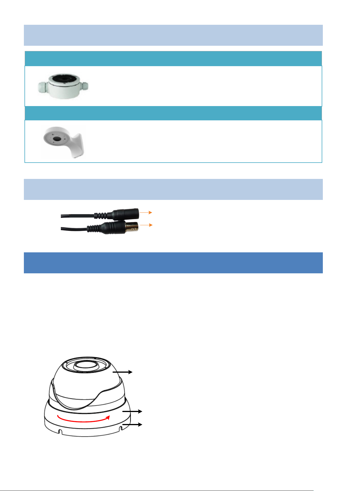
1.4 Optional Accessory
BA-
Color / Material: White / Metal
Size (Φ x H): 138 x 54mm / 5.43” x 2.13”
Weight: 700g / 1.5lb
BA-
Color / Material: White / Metal
Size (W x D x H): 245 x 160 x 163mm / 9.65”x 6.3”x 6.42”
Weight: 2.1kg / 4.63lb
1.5 Cable Description
2. Installation
1. Stick the supplied Mounting Sticker to the surface to mark the 4 screw
positions. Drill four holes on the surface and insert the supplied 4 Screw
Anchors into the screw holes. If you want to run the cable through the
surface, drill a hole within the 4 screw area.
2. Unscrew the Outer Housing by twisting it counterclockwise and then
remove it from the Camera Base.
3. Screw the Camera Base to the surface with the supplied four Screws.

3
Side Cut
Wall
Camera Base
Camera Body
Wall
Camera Base
Camera Body
360
°
180
°
180
°
a. If you want to wire the cables from the Side Cut on the Camera Base:
Attach the Camera Body to the Camera Base and run the cables through
the Camera Base, and then place the cable under the Side Cut. Finally,
screw the Camera Base to the surface with the supplied 4 Screws.
b. If you want to wire the cables through the surface:
Attach and screw the Camera Base to the surface with the supplied 4
Screws, and then attach the Camera Body to the Camera Base.
4. Screw back the Outer Housing and adjust camera angle simultaneously.

4
UP
DN
5. Connect the Power Cable to a 12VDC power source. Connect the Video
Output Cable to a monitor or DVR.
6. You can use the Joystick on the cable to configure camera OSD settings or
switch to different video formats. Remove the Protection Cap from the
Joystick before using it.
Switching Video Format:
• Push the joystick up for 5 sec. to switch to
AHD.
• Push the joystick right for 5 sec. to switch
to TVI.
• Push the joystick down for 5 sec. to switch
to CVI.
• Push the joystick left for 5 sec. to switch to
CVBS.
Configuring OSD Settings:
• Push the Joystick up / down to select
among menu items.
• Push the Joystick left / right to adjust the
level of the selected item.
• Press the Joystick to enter the submenu or
exit the OSD Setup Menu.

5
No
Main
Sub Menu
Sub Menu / Function
AF Mode
One Shot, Manual
D&N Filter
Sync On, Sync Off
Initial
On
Brightness
0-20
Auto
Mode
Normal / Deblur
1/30, 1/60, 1/120, 1/250,
1/30000
Flicker
Sens-Up
Not supported
AGC
0-10
Level
0-20
YEL, CYN, GRN, MAG, RED, BLU, BLK,
WHT
H-POS
0-38
V-POS
0-35
H-SIZE
0-38
V-SIZE
0-35
WDR Mode
Line
Window Zone
0-3
Window Use
On, Off
H-POS
0-3856
V-POS
0-2176
H-SIZE
0-3856
V-SIZE
0-2176
Window Zone
0-3
Window Use
On, Off
POS0-X
0-935
POS0-Y
0-361
POS1-X
0-935
POS1-Y
0-361
POS2-X
0-935
POS2-Y
0-361
POS3-X
0-935
POS3-Y
0-361
Off
Weight
High, Middle, Low
Off
IR LED
Adaptive, Off
Anti-Sat.
0-20
D>N Thres
0-20
N>D Thres
0-20
Delay
High, Middle, Low
Color
IR LED
Adaptive, Off
Anti-Sat.
0-20
3. Configuration in the OSD Menu
1 Motorized
2 Exposure
3 Backlight
Shutter
HLC
BLC
Manual Speed
Color
Box
1/500, 1/1000, 1/2000,
1/4000, 1/8000, 1/15000,
4 Day/Night Mode
WDR
ROI Mode
Polygon
Auto
B/W

6
D>N Thres
0-20
N>D Thres
0-20
Delay
High, Middle, Low
IR LED
Adaptive, Off
Anti-Sat.
0-20
Extern SW
High, Low
D>N Thres
0-20
N>D Thres
0-20
Delay
High, Middle, Low
Auto
Autoext
Preset
C-Temp
3000K, 5000K, 8000K
R-Gain
0-20
B-Gain
0-20
Color Gain
0-20
6
DNR
High, Middle, Low, Off
Sharpness
0-10
Gamma
0.45, 0.55, 0.65, 0.75
Mirror
On, Off
Flip
On, Off
D-Zoom
Not supported
ACE
High, Middle, Low
Mode
Auto, Manual
Level
High, Middle, Low
Off
On
Weight
0%-100%
Off
Zone Num
0-15
Zone Disp
On, Off
H-POS
0-120
V-POS
0-68
H-Size
0-80
V-Size
0-61
Y Level
0-20
CB Level
0-20
CR Level
0-20
Trans
0-3
Off
Zone Num
0-7
Zone Disp
On, Off
POS0-X
0-240
POS0-Y
0-136
POS1-X
0-240
POS1-Y
0-136
POS2-X
0-240
POS2-Y
0-136
POS3-X
0-240
POS3-Y
0-136
Y Level
0-20
CB Level
0-20
Extern
5 Color
AWB
Defog
Shading
Manual
On
7 Image
Privacy
Box
On
Polygon On

7
CR Level
0-20
Trans
0-3
Off
Window Use
0-3
Window Zone
On, Off
Det H-POS
0-96
Det V-POS
0-56
Det H-Size
0-96
Det V-Size
0-56
Sensitivity
0-10
Motion OSD
On, Off
Text Alarm
On, Off
Signal Out
On, Off
Off
Frame Rate
4K/15fps, 4MP/30fps, 1080p/30fps
Freq
60Hz (Auto Detection)
SDI Mode
Not supported
SDI UCC Stop
Not supported
Analog Mode
AHD, TVI, CVI, CVBS
Confirm
Yes
Return
Full
Comp
User
Offset
0-32
Color Space
HD-CbCr, SD-CbCr, YUV
Audio Mic
Not supported
Color Bar
On, Off
Language
ENG, CHN, CHN(S), JPN, KOR, POR
Left-Down
Right-Up
Off
Reset
On
10
Exit
Det Window
8 Motion
9 System
On
Output
Image Range
Cam Title
 Loading...