

Page 1

1
wwww
here barbecuing meets art
here barbecuing meets arthere barbecuing meets art
here barbecuing meets art
ASSEMBLY, OPERATION
& MAINTENANCE INSTRUCTIONS
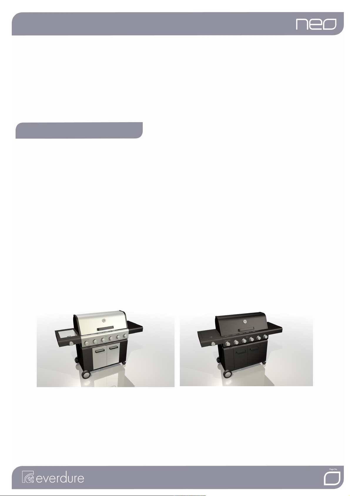
NEO
NEO GRANDE
NEO NEO
GRANDE &
GRANDEGRANDE
& GROSSO
& &
F O R O U T D O O R U S E O N L Y
F O R O U T D O O R U S E O N L Y
F O R O U T D O O R U S E O N L YF O R O U T D O O R U S E O N L Y
GROSSO
GROSSOGROSSO
Page 2
2
ASSEMBLY, OPERATION AND MAINTENANCE INSTRUCTIONS
ASSEMBLY, OPERATION AND MAINTENANCE INSTRUCTIONS
ASSEMBLY, OPERATION AND MAINTENANCE INSTRUCTIONSASSEMBLY, OPERATION AND MAINTENANCE INSTRUCTIONS
FOR
FOR EVERDURE
FOR FOR
EVERDURE 6666 BURNER GAS BARBECUE RANGE
EVERDURE EVERDURE
BURNER GAS BARBECUE RANGE
BURNER GAS BARBECUE RANGE BURNER GAS BARBECUE RANGE
GRANDE
GRANDE AND
GRANDEGRANDE
CONTENTS
CONTENTS
CONTENTSCONTENTS
SECTION PAGE NO.
General Safety Instructions 3
Appliance Details 4
Gas Connections 4
Outdoor Installation Guide 5
Operating Instructions for Barbecue 6
Lighting Procedure 6
Cooking 7
Cleaning and Storage 7
Operating Instructions for Wok Burner 8
Troubleshooting 9
Maintenance 9
Assembly Instructions 10-17
It is important that you retain these instructions for future reference.
It is important that you retain these instructions for future reference.
It is important that you retain these instructions for future reference.It is important that you retain these instructions for future reference.
Grande Grosso
AND GROSSO
AND AND
GROSSO OUTDOOR BARBECUES
GROSSOGROSSO
OUTDOOR BARBECUES
OUTDOOR BARBECUESOUTDOOR BARBECUES
Page 3

3
!
IMPORTANT SAFETY INSTRUCTIONS
IMPORTANT SAFETY INSTRUCTIONS
IMPORTANT SAFETY INSTRUCTIONSIMPORTANT SAFETY INSTRUCTIONS
IMPORTANT
IMPORTANT: Read the assembly instruction section and safety precautions
IMPORTANTIMPORTANT
Read the assembly instruction section and safety precautions of this
Read the assembly instruction section and safety precautionsRead the assembly instruction section and safety precautions
booklet carefully before removing the contents of this carton.
booklet carefully before removing the contents of this carton.
booklet carefully before removing the contents of this carton.booklet carefully before removing the contents of this carton.
of this
of this of this
1. This barbecue and wok burner is for OUTDOOR USE ONLY
indoors.
2. Unsupervised children or pets should not be near a barbecue while cooking or during warm up or cool
down. Ensure children or pets are kept a distance well away from the barbecue whilst it is in use. Ensure
that young children do not play with the appliance.
3. Particular care must be taken when removing the fat tray. Hot fats can cause serious injury.
4. Turn all gas valves off including cylinder after use. Do not allow build up of unburned gas.
5. Do not use this appliance for any purpose other than what it is intended for.
6. Do not move this barbecue while in use as accessible parts may be very hot.
7. People with flammable clothing such as nylon etc. should keep well away from the barbecue when it is
operating.
8. Never leave burners on high for more than 10 minutes unless actually cooking.
9. Always check for leaks when a gas cylinder is replaced or reconnected. Never store more than one gas
cylinder in the trolley at any one time.
10. Sand, kitty litter and fat absorbers should not be used in the fat tray.
11. In case of fat fire turn cylinder off. Fat drip trays should be cleaned and checked before using the
barbecue. Regular cleaning should reduce the build up of fat and food residues which is combustible
and can result in a fat fire. Fat fires can be prevented with diligence in cleaning your fat tray.
Damage as a result of fat fire is not covered by your warranty and voids it.
Fat fires can be prevented with diligence in cleaning your fat tray.
Fat fires can be prevented with diligence in cleaning your fat tray. Fat fires can be prevented with diligence in cleaning your fat tray.
OUTDOOR USE ONLY. This appliance must NOT
OUTDOOR USE ONLYOUTDOOR USE ONLY
NOT be used
NOT NOT
12. For your safety and enjoyment, read all operating instructions before lighting.
13. Ensure that the product has adequate clearance from combustible materials. The appliance is designed
so that heat will not affect the trolley. All combustible materials must be kept more than 250mm from the
sides of the trolley and more than 1500mm above the cooking surface of the barbecue.
14. If the burner makes a hissing sound when lit, it may be burning inside. Turn the burner off, allow to cool
and try ignition again. Keep your barbecue protected against strong wind – if this cannot be avoided,
always check that the burners remain alight if operating the barbecue in windy conditions.
15. This appliance is not intended for use by young children or infirm persons.
16. When the wok burner is in use or is still hot, the lid must not be placed in the closed position.
17. Do not carry out any servicing on the gas manifold of the barbecue yourself – this must only be done by
authorised technicians.
18. We recommend that you regularly maintain your barbecue and keep it in good condition. This can be
achieved by following the cleaning and maintenance suggestions in this booklet.
DO NOT
DO NOT
DO NOT
DO NOT
DO NOT
DDDDO NOT
DO NOT OPERATE THIS APPLIANCE BEFORE READING THE
DO NOT DO NOT
DO NOT PLACE ARTICLES ON OR AGAINST THIS APPLIANCE
DO NOT DO NOT
DO NOT STORE CHEMICALS OR FLAMMABLE MATERIALS OR
DO NOTDO NOT
DO NOT OPERATE THIS APPLIANCE INDOORS
DO NOTDO NOT
DO NOT ENCLOSE THIS APPLIANCE
DO NOTDO NOT
O NOT LIGHT OR OPERATE WITH COVER ON
O NOTO NOT
INSTRUCTION BOOKLET
SPRAY AEROSOLS NEAR THIS APPLIANCE
Page 4
4
!
APPLIANCE DETAILS
APPLIANCE DETAILS
APPLIANCE DETAILSAPPLIANCE DETAILS
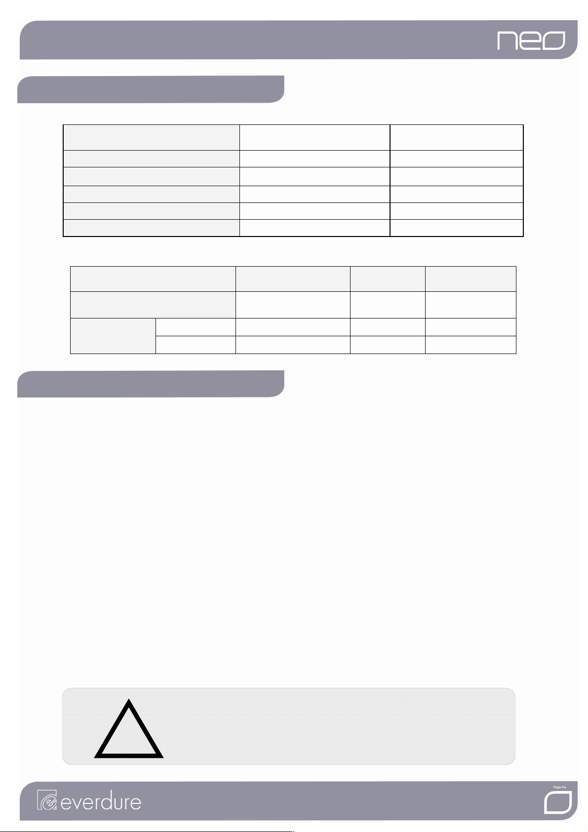
Gas Type:
Gas Type:
Gas Type:Gas Type:
Burner
Burner Pressure:
BurnerBurner
Injector Diameter:
Injector Diameter: Ø0.95 mm Ø1.65 mm
Injector Diameter:Injector Diameter:
Heat Input:
Heat Input: 70 MJ/ hr 75 MJ/ hr
Heat Input:Heat Input:
Wok Injector Diameter:
Wok Injector Diameter: Ø0.90 mm Ø1.65 mm
Wok Injector Diameter:Wok Injector Diameter:
Wok Heat Input:
Wok Heat Input: 10.5MJ/hr 12.5MJ/hr
Wok Heat Input:Wok Heat Input:
Note: The size of the injector diameter is stamped on one of the hexagon faces (e.g. ‘104’ for Ø1.04mm injector).
Pressure: 2.75 kPa 0.95 kPa
Pressure: Pressure:
(Propane and/or Butane gas)
Universal LPG
Natural Gas
Barbecue only
Barbecue only 1004 545 220
Barbecue onlyBarbecue only
Barbecue and
Barbecue and
Barbecue and Barbecue and
Trol
Trolley
ley
TrolTrol
leyley
Grande 1710 640 1220
Grosso 1680 640 1220
LENGTH (mm)
LENGTH (mm) WIDTH (mm)
LENGTH (mm)LENGTH (mm)
WIDTH (mm) HEIGHT (mm)
WIDTH (mm)WIDTH (mm)
HEIGHT (mm)
HEIGHT (mm)HEIGHT (mm)
GAS CONNECTIONS
GAS CONNECTIONS
GAS CONNECTIONSGAS CONNECTIONS
LOCAL AUTHORITY REQUIREMENTS
LOCAL AUTHORITY REQUIREMENTS
LOCAL AUTHORITY REQUIREMENTSLOCAL AUTHORITY REQUIREMENTS
Check Gas Type and specifications plate on the left-hand side of the barbecue. All gas fitting work, service and repairs
can only be performed by an authorised person in accordance with AS5601 / AG601 and local gas regulations.
NATURAL GAS
NATURAL GAS
NATURAL GASNATURAL GAS
Neo 6 burner barbecues can be converted to use natural gas ONLY with a Neo NG 6 burner conversion kit. Fit the NG
manifolds, regulator and NG hose. This conversion can ONLY
with AS5601 / AG601 and local gas regulations.
Note: The burner pressure (as noted on the appliance details) MUST be checked after installation by turning on and
measuring at the regulator output test point. All connections must be checked for leaks.
FOR
FOR GAS
GAS CYLINDER CONNECTION
FOR FOR
1. To achieve the optimum performance from your Barbecue, an approved gas cylinder (POL fitting) of 9kg capacity
must be used.
2. Do not connect gas to a barbecue that is not secured in a trolley.
3. Connect the cylinder to the barbecue, via the hose and regulator. Firmly tighten joints, but do not over-tighten. Take
LEAK TESTING
LEAK TESTING
LEAK TESTINGLEAK TESTING
1. Make sure gas controls are Off
2. Check for leaking joints by brushing with solution of half-liquid detergent and half water. If a leak is present, bubbles
will appear (or you will hear a hissing sound). Retightening connections can generally repair a leaking joint. You must
also check the gas hose and connection at the gas cylinder, and at the wok burner. If a leak cannot be resolved, do
not proceed.
CYLINDER CONNECTION
GASGAS
CYLINDER CONNECTION CYLINDER CONNECTION
care not to damage the regulator fitting.
Off and turn the cylinder valve On
OffOff
LEAK TEST ALL CONNECTIONS, INCL
LEAK TEST ALL CONNECTIONS, INCLUDING THE CONNECTION
LEAK TEST ALL CONNECTIONS, INCLLEAK TEST ALL CONNECTIONS, INCL
TO THE GAS CYLINDER
TO THE GAS CYLINDER.
TO THE GAS CYLINDERTO THE GAS CYLINDER
DO NOT USE NAKED FLAME FOR LOCATING GAS LEAKS.
DO NOT USE NAKED FLAME FOR LOCATING GAS LEAKS.
DO NOT USE NAKED FLAME FOR LOCATING GAS LEAKS.DO NOT USE NAKED FLAME FOR LOCATING GAS LEAKS.
IF A LEAK PERSISTS CALL AN AUTHORISED GAS FITTER.
IF A LEAK PERSISTS CALL AN AUTHORISED GAS FITTER.
IF A LEAK PERSISTS CALL AN AUTHORISED GAS FITTER.IF A LEAK PERSISTS CALL AN AUTHORISED GAS FITTER.
ONLY be performed by an authorised person in accordance
ONLYONLY
On.
OnOn
UDING THE CONNECTION
UDING THE CONNECTION UDING THE CONNECTION
Page 5
5
OUTDOOR INSTALLATION GUIDE
OUTDOOR INSTALLATION GUIDE
OUTDOOR INSTALLATION GUIDEOUTDOOR INSTALLATION GUIDE
This Appliance shall only be used in an above ground open-air situation with natural ventilation, without
stagnant areas, where gas leakage and products of combustion are rapidly dispersed by wind and natural
convection.
This appliance
This appliance must not
This appliance This appliance
other enclo
other enclosed areas. The barbecue is not intended to be installed in or used on recreational vehicles
other encloother enclo
(e.g. boats, camping vans) and should not be placed close to or under any surfaces that will burn or
(e.g. boats, camping vans) and should not be placed close to or under any surfaces that will burn or
(e.g. boats, camping vans) and should not be placed close to or under any surfaces that will burn or (e.g. boats, camping vans) and should not be placed close to or under any surfaces that will burn or
are sensitive to heat. Do not block/obstruct the flow of air
are sensitive to heat. Do not block/obstruct the flow of air and combustion around the barbecue
are sensitive to heat. Do not block/obstruct the flow of air are sensitive to heat. Do not block/obstruct the flow of air
housing while in use.
housing while in use.
housing while in use.housing while in use.
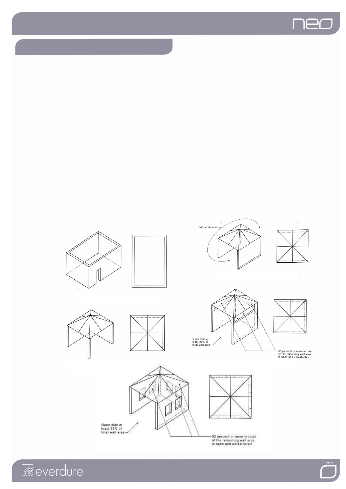
Any enclosure in which the appliance is used shall comply with one of the following:
Any enclosure in which the appliance is used shall comply with one of the following:
Any enclosure in which the appliance is used shall comply with one of the following:Any enclosure in which the appliance is used shall comply with one of the following:
• An enclosure with walls on all sides, but at least one permanent opening at ground level and no
overhead cover.
• Within a partial enclosure that includes an overhead cover and no more than two walls
• Within a partial enclosure that includes an overhead cover and more than two walls, the following shall
apply-
In the case of balconies, at least 20% of the total of the side, back and front wall areas shall be and remain
open and unrestricted.
must not be used indoors. Do not use your barbecue in garages, porches, sheds or
must notmust not
sed areas. The barbecue is not intended to be installed in or used on recreational vehicles
sed areas. The barbecue is not intended to be installed in or used on recreational vehicles sed areas. The barbecue is not intended to be installed in or used on recreational vehicles
(i) at least 25% of the total wall area is completely open: and
(ii) at least 30% of the remaining wall area is open and unrestricted.
be used indoors. Do not use your barbecue in garages, porches, sheds or
be used indoors. Do not use your barbecue in garages, porches, sheds or be used indoors. Do not use your barbecue in garages, porches, sheds or
and combustion around the barbecue
and combustion around the barbecue and combustion around the barbecue
Page 6

6
!
OPERATING IN
OPERATING INSTRUCTIONS
OPERATING INOPERATING IN
GAS TYPE AND CONSUMPTION
GAS TYPE AND CONSUMPTION
GAS TYPE AND CONSUMPTIONGAS TYPE AND CONSUMPTION
The barbecue is designed to operate on Universal LP Gas only (Propane and/or Butane gas) and Natural Gas
(using a conversion kit). Gas consumption, Pressure and Injector Orifice size are shown on the Data Plate
found on the left-hand side of the barbecue.
GAS
GAS CONTROL
CONTROL KNOBS
GAS GAS
CONTROLCONTROL
The gas control knob locks in both the Off
clockwise, gas flow will gradually increase until the High
and gas flow will decrease until a simmer level is reached at Low
must be turned clockwise from Low
VAPOURISER
VAPOURISER
VAPOURISERVAPOURISER
Prior to using the barbecue, ensure the vapouriser is located in the correct position below the grill plate.
HOT PLATE, GRILL PLATE
HOT PLATE, GRILL PLATE, BAKING DISH
HOT PLATE, GRILL PLATEHOT PLATE, GRILL PLATE
Prior to using the barbecue, it’s advisable to cure the cooking surface. Wash the hot plate and grill plate, then
cover with olive or vegetable oil, light all burners and leave on until oil is absorbed, then wipe with a dry cloth.
STRUCTIONS
STRUCTIONSSTRUCTIONS
KNOBS
KNOBS KNOBS
Low, depressed at High
LowLow
, BAKING DISH
, BAKING DISH, BAKING DISH
Off and High
OffOff
High positions. By depressing the knob and turning anti-
HighHigh
High position is reached. Continue turning in this direction
High High
Low. To turn gas flow off the gas control knob
LowLow
High and turned until the Off
HighHigh
Off position is reached.
OffOff
DRIP TRAY
DRIP TRAY
DRIP TRAYDRIP TRAY
Prior to use check that the drip tray is clean and lined with aluminium foil.
UNDER NO CIRCUMSTANC
UNDER NO CIRCUMSTANCES MUST SAND, FAT AB
UNDER NO CIRCUMSTANCUNDER NO CIRCUMSTANC
OR KITTY LITTE
OR KITTY LITTER BE USED IN THE DRI
OR KITTY LITTEOR KITTY LITTE
LIGHTING PROCEDURE
LIGHTING PROCEDURE
LIGHTING PROCEDURELIGHTING PROCEDURE
ES MUST SAND, FAT ABSORBENTS
ES MUST SAND, FAT ABES MUST SAND, FAT AB
R BE USED IN THE DRIP TRAY
R BE USED IN THE DRIR BE USED IN THE DRI
SORBENTS
SORBENTSSORBENTS
P TRAY
P TRAYP TRAY
READ ALL OPERATING I
MAKE SURE ALL GAS
LIGHTING THE BARBECUE
LIGHTING THE BARBECUE
LIGHTING THE BARBECUELIGHTING THE BARBECUE
The 6 burner barbecue has a rotary ignition system built into the second gas control in from either end, which
ignites the corresponding burner. The remaining burners are ignited by a cross over channel. Pushing either
of these control knobs in, and rotating the control knob in an anti-clockwise direction (starting at off
a spark to ignite an extended pilot flame, which will in turn light the burner in front of the control knob. Once
the knob is released, the pilot flame will extinguish. Visually check to see if the burner has ignited. If the
burner does not light, turn gas control off (turn the control knob clockwise) and allow the unburned gas to
dissipate before attempting ignition again. If ignition continues to fail refer, to the “Trouble shooting” section.
To achieve ignition on the remaining burners, turn an adjacent burner control knob to high
ignite from the first burner.
MANUAL IGNITION
MANUAL IGNITION
MANUAL IGNITIONMANUAL IGNITION
To help light the barbecue manually, a match holder and chain has been provided, and should be attached to
the right hand servery. The right hand burner can then be lit by lighting a match, fitting it into the holder and
pushing the match through to the right hand burner. After the initial burner is lit, the others can be ignited as
described above.
READ ALL OPERATING INSTRUCTIONS BEFORE L
READ ALL OPERATING IREAD ALL OPERATING I
MAKE SURE ALL GAS CONTROL
MAKE SURE ALL GAS MAKE SURE ALL GAS
POSITION AND OPEN CY
POSITION AND OPEN CYLINDER VALVE.
POSITION AND OPEN CYPOSITION AND OPEN CY
NSTRUCTIONS BEFORE LIGHTING.
NSTRUCTIONS BEFORE LNSTRUCTIONS BEFORE L
CONTROL KNOBS ARE IN THE ‘O
CONTROLCONTROL
KNOBS ARE IN THE ‘OFF’
KNOBS ARE IN THE ‘O KNOBS ARE IN THE ‘O
LINDER VALVE.
LINDER VALVE.LINDER VALVE.
IGHTING.
IGHTING.IGHTING.
FF’
FF’ FF’
off), will cause
offoff
high and the burner will
highhigh
Page 7

7
COOKING
COOKING
COOKINGCOOKING
GENERAL COOKING GUIDE
GENERAL COOKING GUIDE
GENERAL COOKING GUIDEGENERAL COOKING GUIDE
A fairly protected location is desirable for pleasant and efficient cooking. IMPORTANT!
drastically reduce cooking efficiency. As a guide, allow 10 minutes with the burners on high, to heat cooking
area. A little cooking fat (or olive oil) on the grill will prevent sticking. Cooking time for a 20mm thick steak cooked
to medium on the char grill is approximately 15 minutes (7.5 minutes per side) with the burners on high. Turn
burners down a little when full heat is not required and to LOW
As a guide for Hood closed
plate, baking dish and vapouriser. Position the grill plate central over the two centre burners. Place either the
roasting dish or a foil baking dish in the centre of the bbq. Fill the dish with 2 cm of water. Place a suitably sized
rack in the dish. Place food on the rack so that any fats will drip into the water in the bottom of the dish. The water
will also keep the food moist during cooking. With the hood open light the bbq as per normal lighting
instructions, then close the hood and turn off the two central burners. Leave the outer two burners on high and
the middle burners on low. This is most important – if left on the two centre burners will cause overheating and
spoil the food. A 10 minute pre-heat time is generally required to get the temperature to the correct level. As a
rough guide to the cooking times for roast beef, allow 30 to 50 minutes cooking time per kilogram for rare to well
done respectively. It is recommended that the food be turned half way through the cooking time, for evenness of
cooking. Remember, never use the roasting hood with all the burners on high as this will cause severe
overheating and may damage the hood and bbq. During cooking, fat and scrapings will drip through to the drip
tray. Do not allow excess fat to build up in the drip tray. Clean the drip tray and replace the aluminium foil before
use. This is a general guide for roasting only – please check www.everdure.com for any updated cooking guides.
AFTER COOKING
AFTER COOKING
AFTER COOKINGAFTER COOKING
1. When finished, make sure burner control knobs are turned OFF
2. TURN OFF THE GAS SUPPLY AT THE CYLINDER
TURN OFF THE GAS SUPPLY AT THE CYLINDER.
TURN OFF THE GAS SUPPLY AT THE CYLINDERTURN OFF THE GAS SUPPLY AT THE CYLINDER
3. Immediately after cooking and whilst the barbecue is still warm, remove scraps from the grill with a scraper.
4. Excess fat and meat scraps can be scraped off the vapouriser by removing the grill to gain access.
WARNING
WARNING: Some surfaces may still be hot.
WARNINGWARNING
5. Clean the fat tray and replace the aluminium foil after or before each use of the appliance.
6. Once the barbecue is cool close the roasting hood and wipe off any fat splatter from the trolley with a clean
rag.
Hood closed cooking, use as per the following instructions: Open hood and remove the solid
Hood closedHood closed
LOW when not cooking.
LOWLOW
OFF.
OFFOFF
IMPORTANT! Strong winds will
IMPORTANT!IMPORTANT!
CLEANING
CLEANING AND STORAGE
CLEANINGCLEANING
AND STORAGE
AND STORAGE AND STORAGE
CLEANING
CLEANING
CLEANINGCLEANING
Painted surfaces can be cleaned using a mild household detergent or cleaner. It is advisable to test cleaners on a
small section of the appliance first. It is recommended to clean the stainless steel surfaces with clean water only
(no detergents to be used) or use a stainless steel cleaner. Failure to follow these instructions may void your
warranty. Over time, stainless steel will be affected by “tea staining” or “bronzing” (brown discoloration of stainless
steel). This can be reduced by washing the surface with mild detergent and warm water, followed by rinsing with
clean cold water. Dry the surface afterwards.
NEVER
NEVER use paint thinners or similar solvents for cleaning and NEVER
NEVERNEVER
STORAGE
STORAGE
STORAGESTORAGE
WARNING
WARNING:::: When the appliance is not in use, the cylinder valve must be turned OFF,
WARNINGWARNING
cylinder together must be stored outdoors in a well ventilated area. However it is permissible to store the
appliance (but not the cylinder) indoors. Ensure a small amount of fat or oil is on the barbecue plates to prevent
rust.
STORE CYLINDER IN A WELL VENTILATED AREA
STORE CYLINDER IN A WELL VENTILATED AREA OUT OF REACH OF CHILDREN
STORE CYLINDER IN A WELL VENTILATED AREASTORE CYLINDER IN A WELL VENTILATED AREA
NEVER pour cold water over hot surfaces.
NEVERNEVER
OFF, the appliance and the
OFF, OFF,
OUT OF REACH OF CHILDREN
OUT OF REACH OF CHILDRENOUT OF REACH OF CHILDREN
Page 8

8
When the gas cylinder is disconnected, replace the plug or cap on the valve outlet.
For extended storage it is suggested that the primary air port of the burners be covered against the
penetration of insects or vermin. Spiders and small insects can spin webs or nest in the burner rails/tubes,
which could lead to obstruction in the gas and air flow, resulting in a fire in an around the burner rails/tubes.
This type of fire is called a flash-back and can cause serious damage to your barbecue and create an unsafe
operating condition. To prevent this, regularly inspect and clean the burners. A barbecue cover can be
placed over the appliance for extra protection, and to reduce this.
To extend the life of your barbecue and trolley and to keep it looking great, we recommend using a
Weatherproof Cover.
GAS SUPPLY
GAS SUPPLY
GAS SUPPLYGAS SUPPLY
1. Inspect the gas supply hose for any deterioration and replace it if necessary.
2. Test the gas circuit for leaks and remedy any found. See leak testing instruction.
TROLLEY
TROLLEY
TROLLEYTROLLEY
1. Check all fasteners for tightness and re tighten where necessary to ensure rigidity of the structure.
2. Wipe over barbecue trolley with a clean cloth.
OPERATING INSTRUCTIONS FOR
OPERATING INSTRUCTIONS FOR WOK BURNER
OPERATING INSTRUCTIONS FOROPERATING INSTRUCTIONS FOR
WOK BURNER
WOK BURNER WOK BURNER
GAS CONNECTION
GAS CONNECTION
GAS CONNECTIONGAS CONNECTION
Attach small hose from wok burner gas valve to barbecue manifold. Connect gas hose and regulator to the
cylinder. Before turning gas cylinder on please ensure that the gas valves on the barbecue and wok burner
are in the off position.
Turn gas supply on and check for leaks by applying a soap solution to all connections with a brush. If a leak
is detected, retighten the connection and test for leaks again. Never check for leaks with the use of a flame.
BEFORE IGNITING T
BEFORE IGNITING THE BARBECUE ENSURE T
BEFORE IGNITING TBEFORE IGNITING T
BARBECUE AND THE WOK
BARBECUE AND THE WOK BURNER
BARBECUE AND THE WOKBARBECUE AND THE WOK
LIGHTING INSTRUCTION
LIGHTING INSTRUCTIONSSSS
LIGHTING INSTRUCTIONLIGHTING INSTRUCTION
Important: The lid must be open when lighting the burner and during normal operation.
Important: The lid must be open when lighting the burner and during normal operation.
Important: The lid must be open when lighting the burner and during normal operation.Important: The lid must be open when lighting the burner and during normal operation.
1. Push in and turn the control knob to HIGH.
2. The built-in ignitor will light the burner.
3. If burner does not light, return knob to the OFF position and retry 5 times.
4. If the burner does not light, leave the knob in the OFF position, and wait 5 minutes before retrying.
HE BARBECUE ENSURE THAT ALL VALVES ON TH
HE BARBECUE ENSURE THE BARBECUE ENSURE T
BURNER ARE IN THE OFF POSIT
BURNER BURNER
HAT ALL VALVES ON THE
HAT ALL VALVES ON THHAT ALL VALVES ON TH
ARE IN THE OFF POSITION.
ARE IN THE OFF POSITARE IN THE OFF POSIT
ION.
ION.ION.
E
E E
CARE AND CLEANING
CARE AND CLEANING
CARE AND CLEANINGCARE AND CLEANING
Before cleaning, ensure the appliance has cooled down and is safe to touch. Remove the trivet plate and
wipe down the burner and spill bowl with a clean damp cloth. Do not use harsh detergents or scourers as
damage may occur to the surfaces.
Page 9

9
TROUBLESHOOTING
TROUBLESHOOTING
TROUBLESHOOTINGTROUBLESHOOTING
Burner will no
Burner will not ignite when using the igniter:
Burner will noBurner will no
Cylinder valve is not on Turn cylinder valve on
Cylinder is empty Replace with a full cylinder
Igniter button is not working Check connections
Igniter is not sparking Remove plate and visually check ignition box for a spark. If there is no
Injector is blocked Clean injector with a toothbrush. Do not drill out or use wire. Do not
Burner flame is erratic:
Burner flame is erratic:
Burner flame is erratic:Burner flame is erratic:
Burner is blocked Remove burner and check for obstruction
t ignite when using the igniter:
t ignite when using the igniter:t ignite when using the igniter:
spark contact, check connections.
remove injector.
Contact authorised service agent
Flame is burning inside burner
(hissing sound)
Regulator is faulty Contact authorised service agent
Injector is partially blocked Clean injector with a toothbrush. Do not drill out or use wire. Do not
Gas is leaking from connections:
Gas is leaking from connections:
Gas is leaking from connections:Gas is leaking from connections:
Connections are loose Tighten loose connections (do not over-tighten) and leak test under
Hose has deteriorated Replace hose and leak test after replacement.
Gas valve is faulty Contact an authorised service agent
Threads are damaged Contact an authorised service agent
MAINTENANCE
MAINTENANCE
MAINTENANCEMAINTENANCE
It is recommended that, at the commencement of each barbecue season, the following maintenance be
conducted.
BURNERS
BURNERS
BURNERSBURNERS
1. Remove the burner and inspect the port holes, primary air inlet and mixing throat for any signs of
blockage. Clean out with compressed air or a length of wire if necessary.
2. Wire brush the outside of the burner to remove rust and dirt.
3. Replace the burner.
GAS SUPPLY
GAS SUPPLY
GAS SUPPLYGAS SUPPLY
1. Inspect the gas supply hose for any deterioration and replace it if necessary.
2. Test the gas circuit for leaks and remedy any found.
TROLLEY
TROLLEY
TROLLEYTROLLEY
1. Check all fasteners for tightness and re-tighten where necessary to ensure rigidity of the structure.
2. Wipe over barbecue trolley with a clean cloth.
Turn off burner, allow to cool and re-ignite
remove injector. Contact authorised service agent.
pressure with soapy water solution. Refer to leak testing instructions
Page 10

10
Phillips Screwdriver
Phillips ScrewdriverPhillips Screwdriver
Phillips Screwdriver
Spanner
SpannerSpanner
Spanner
BARBECUE ASSEMBLY
BARBECUE ASSEMBLY
BARBECUE ASSEMBLYBARBECUE ASSEMBLY
CHECK AND REMOVE THE BBQ PARTS FRON THE CARTONS
CHECK AND REMOVE THE BBQ PARTS FRON THE CARTONS
CHECK AND REMOVE THE BBQ PARTS FRON THE CARTONSCHECK AND REMOVE THE BBQ PARTS FRON THE CARTONS
NEO
2.FAT TRAY HANDLE
1.FAT TRAY
25.BURNERS
23.WOK SERVERY
NEO Grande
NEONEO
6.COOKING PLATE
Grande
GrandeGrande
26.BAKING DISH
3.WARMING RACK
4.GRILL
5.VAPOURISER
7.SIDE SERVERY
AND DRAWER
27.SERVERY BRACKET
24.MATCH HOLDER
8.BODY AND HOOD ASS'Y
9.TROLLEY TOP PANEL
10.MAGNETS (2PCS)
22.REAR PANEL
21.LEFT SIDE PANEL
11.RIGHT SIDE PANEL
12.DOORPOSTS (2PCS)
13.DOOR HANDLES (2PCS)
14.RIGHT DOOR
20.AXLE
19.WHEELS (2PCS)
18.WHEEL DECALS (2PCS)
PARTS REQU
PARTS REQUIRED
PARTS REQUPARTS REQU
Make sure you thoroughly inspect parts before assembly and do not assemble or operate a barbecue that
appears damaged.
IRED / INVENTORY
/ INVENTORY
IREDIRED
/ INVENTORY / INVENTORY
17.LEFT DOOR
15.TROLLEY BOTTOM PANEL
16.CASTOR (2PCS)
ITEM
ITEM
ITEMITEM
A
B
C
D
E
The use of an adjustable spanner and a Phillips screwdriver will be required.
PICTURE
PICTURE NAME AND QUANTITY
PICTUREPICTURE
NAME AND QUANTITY ITEM
NAME AND QUANTITYNAME AND QUANTITY
SCREW M6X16…......14PCS F
SCREW M5X15….…..36PCS G
SCREW M4X8…….......8PCS H
SCREW M3X12….…....4PCS I
FLAT HEAD SCREW.....4PCS J
ITEM PICTURE
ITEMITEM
PICTURE NAME AND QUANTITY
PICTUREPICTURE
NAME AND QUANTITY
NAME AND QUANTITYNAME AND QUANTITY
NUT M6........................ 14PCS
LOCK NUT M10….…...…2PCS
LOCK NUT M3……....…..4PCS
SPRING WASHER D6.....14PCS
FIBRE WASHER M5.........4PCS
Page 11

11
Phillips Screwdriver
Phillips ScrewdriverPhillips Screwdriver
Phillips Screwdriver
Spanner
SpannerSpanner
Spanner
NEO Grosso
2.FAT TRAY HANDLE
1.FAT TRAY
25.BURNERS
23.WOK SERVERY
22.REAR PANEL
21.LEFT SIDE PANEL
6.COOKING PLATE
26.BAKING DISH
3.WARMING RACK
4.GRILL
5.VAPOURISER
7.SIDE SERVERY
24.MATCH HOLDER
8.BODY AND HOOD ASS'Y
9.TROLLEY TOP PANEL
10.MAGNETS (2PCS)
11.RIGHT SIDE PANEL
12.DOORPOSTS (2PCS)
13.DOOR HANDLES (2PCS)
20.AXLE
14.RIGHT DOOR
15.TROLLEY BOTTOM PANEL
19.WHEELS (2PCS)
18.WHEEL DECALS (2PCS)
16.CASTOR (2PCS)
17.LEFT DOOR
PA
PARTS REQUIRED
RTS REQUIRED / INVENTORY
PAPA
RTS REQUIREDRTS REQUIRED
Make sure you thoroughly inspect parts before assembly and do not assemble or operate a barbecue that
appears damaged.
/ INVENTORY
/ INVENTORY / INVENTORY
ITEM
ITEM
ITEMITEM
A
B
C
D
E
The use of an adjustable spanner and a Phillips screwdriver will be required.
PICTURE
PICTURE NAME AND QUANTITY
PICTUREPICTURE
NAME AND QUANTITY ITEM
NAME AND QUANTITYNAME AND QUANTITY
SCREW M6X16….…..14PCS F
SCREW M5X15….…..36PCS G
SCREW M4X8…….......6PCS H
SCREW M3X12….…....4PCS I
FLAT HEAD SCREW..…4PCS J
ITEM PICTURE
ITEMITEM
PICTURE NAME AND QUANTITY
PICTUREPICTURE
NAME AND QUANTITY
NAME AND QUANTITYNAME AND QUANTITY
NUT M6........................ 14PCS
LOCK NUT M10….…...…2PCS
LOCK NUT M3……....…..4PCS
SPRING WASHER D6.....14PCS
FIBRE WASHER M5.........4PCS
Page 12

12
STEP 1: Fitting the wheels and castors to the trolley bottom plate.
STEP 1: Fitting the wheels and castors to the trolley bottom plate.
STEP 1: Fitting the wheels and castors to the trolley bottom plate.STEP 1: Fitting the wheels and castors to the trolley bottom plate.
PARTS REQUIRED
PARTS REQUIRED
PARTS REQUIRED PARTS REQUIRED
ITEM
ITEM
ITEMITEM
A
I
FIGURE
FIGURE NAME AND QUANTITY
FIGUREFIGURE
NAME AND QUANTITY ITEM
NAME AND QUANTITYNAME AND QUANTITY
SCREW M6X16…..….14PCS F
SPRING WASHER......14PCS G
ITEM FIGURE
ITEMITEM
FIGURE NAME AND QUANTITY
FIGUREFIGURE
NAME AND QUANTITY
NAME AND QUANTITYNAME AND QUANTITY
NUT M6........................14PCS
LOCK NUT M10……...…2PCS
Fix the axle to the trolley bottom panel using six screws, spring washers and nuts. Fit the wheels onto the axle
with the large lock nuts, and cover with the wheel decals. Fix the castors to the trolley bottom panel using
eight screws, spring washers and nuts. Tighten all nuts firmly.
STEP 2: Fitting the door magnets to the trolley top and bottom pa
STEP 2: Fitting the door magnets to the trolley top and bottom pannnneeeelllls.
STEP 2: Fitting the door magnets to the trolley top and bottom paSTEP 2: Fitting the door magnets to the trolley top and bottom pa
PARTS REQUIRED
PARTS REQUIRED
PARTS REQUIRED PARTS REQUIRED
ITEM
ITEM
ITEMITEM
D
FIGURE
FIGURE NAME AND QUANTITY
FIGUREFIGURE
NAME AND QUANTITY ITEM
NAME AND QUANTITYNAME AND QUANTITY
SCREW M3X12…........4PCS H
ITEM FIGURE
ITEMITEM
FIGURE NAME AND QUA
FIGUREFIGURE
s.
s.s.
NAME AND QUANTITY
NAME AND QUANAME AND QUA
LOCK NUT M3…….....…4PCS
NTITY
NTITYNTITY
Place a door magnet on the trolley bottom panel (over the mounting bracket) and fix in place using two M3
screws and two M3 nuts. Repeat for the trolley top panel.
10
D
H
9
15
Page 13

13
STEP 3: Fitting the trolley rear panel to the trolley bottom pa
STEP 3: Fitting the trolley rear panel to the trolley bottom pannnneeeellll....
STEP 3: Fitting the trolley rear panel to the trolley bottom paSTEP 3: Fitting the trolley rear panel to the trolley bottom pa
PARTS REQUI
PARTS REQUIRED
PARTS REQUIPARTS REQUI
ITEM
ITEM
ITEMITEM
B
FIGURE
FIGURE NAME AND QUANTITY
FIGUREFIGURE
RED
RED RED
NAME AND QUANTITY
NAME AND QUANTITYNAME AND QUANTITY
SCREW M5X15…..............2PCS
Align the trolley rear panel over the rear edge of the trolley bottom panel and fix into place with two M5 screws
(the edges should be flush). Tighten the screws firmly.
STEP 4: Fitting the trolley side panels to the trolley bottom p
STEP 4: Fitting the trolley side panels to the trolley bottom panel
STEP 4: Fitting the trolley side panels to the trolley bottom pSTEP 4: Fitting the trolley side panels to the trolley bottom p
PARTS REQUIRED
PARTS REQUIRED
PARTS REQUIRED PARTS REQUIRED
ITEM
ITEM
ITEMITEM
B
FIGURE
FIGURE NAME AND QUANTITY
FIGUREFIGURE
NAME AND QUANTITY
NAME AND QUANTITYNAME AND QUANTITY
SCREW M5X15…..............8PCS
anel....
anelanel
Align the left hand trolley side panel (with the access hole for the hose and regulator to the top front corner) on
top of the left hand edge of the trolley bottom panel and in front of the trolley rear panel. Fix into place using
four M5 screws. Repeat for the right hand trolley side panel. Tighten the screws firmly.
Page 14

14
STEP 5: Fitting the
STEP 5: Fitting the door posts
STEP 5: Fitting the STEP 5: Fitting the
door posts to th
door postsdoor posts
to the trolley bottom panel
to th to th
e trolley bottom panel and side panels
e trolley bottom panele trolley bottom panel
and side panels....
and side panels and side panels
PARTS REQUIRED
PARTS REQUIRED
PARTS REQUIRED PARTS REQUIRED
ITEM
ITEM
ITEMITEM
B
Align a door post so that the larger face is at the front, and the large return is against the trolley side panel. Fix
into place with two M5 screws through the bottom of the door panel into the trolley bottom panel, and two M5
screws through the front edge of the side panel and into the door post. Repeat for the other door post.
Tighten the screws firmly.
FIGURE
FIGURE NAME AND QUANTITY
FIGUREFIGURE
NAME AND QUANTITY
NAME AND QUANTITYNAME AND QUANTITY
SCREW M5X15…..............8PCS
STEP
STEP 6666: Fitting the trolley
STEP STEP
: Fitting the trolley top
: Fitting the trolley : Fitting the trolley
PARTS REQUIRED
ITEM
ITEM
ITEMITEM
B
FIGURE
FIGURE NAME AND QUANTITY
FIGUREFIGURE
NAME AND QUANTITY
NAME AND QUANTITYNAME AND QUANTITY
SCREW M5X15…..............10PCS
top panel.
panel.
toptop
panel. panel.
Place the trolley top panel (door magnet to the front) on a protected surface and align the rest of the trolley on
top of it. Fix the trolley top panel to the 5 panels with ten M5 screws. Tighten the screws firmly.
Page 15

15
STEP
STEP 7777: Fitting
STEP STEP
PARTS REQUIRED
PARTS REQUIRED
PARTS REQUIRED PARTS REQUIRED
ITEM
ITEM
ITEMITEM
C
: Fitting the
: Fitting: Fitting
FIGURE
FIGURE NAME AND QUANTITY
FIGUREFIGURE
the door handles and doors
door handles and doors....
the the
door handles and doorsdoor handles and doors
NAME AND QUANTITY
NAME AND QUANTITYNAME AND QUANTITY
SCREW M4X8..…..............4PCS
Screw the two door handles to the fronts of the doors using two M4 screws each. To fit the doors into
the trolley, firstly place the bottom (fixed) hinge into the door hole in the trolley bottom panel, then fit the
top hinge by squeezing the spring hinge down and angling the door into place (the spring hinge will
extend to fit the hole in the trolley top panel).
STEP 8: Fitting the
STEP 8: Fitting the barbecue body to the trolley
STEP 8: Fitting the STEP 8: Fitting the
barbecue body to the trolley....
barbecue body to the trolleybarbecue body to the trolley
PARTS REQUIRED
PARTS REQUIRED
PARTS REQUIRED PARTS REQUIRED
ITEM
ITEM
ITEMITEM
E
Place the barbecue body onto the trolley and line up the four mounting holes. Place a thin fiber washer
onto each of the four flat head screws, and screw the two parts down together. Keep the face of the
screws as flush as possible to the edge of the barbecue body, to help the fat tray slide. Take the four
cast iron burners and remove the wire clips. Fit the burners by placing its throat over a gas valve (behind
each control knob). Lower the tab at the rear of the burner into the hole in the rear of the barbecue body.
Remove the barbecue rear panel (4 screws) and clip the burners into place with the clips. Replace the
rear panel.
FIGURE
FIGURE NAME AND QUANT
FIGUREFIGURE
NAME AND QUANTITY
NAME AND QUANTNAME AND QUANT
FLAT HEAD SCREW M5..4PCS J
ITY ITEM
ITYITY
ITEM FIGURE
ITEMITEM
FIGURE NAME AND QUANTITY
FIGUREFIGURE
NAME AND QUANTITY
NAME AND QUANTITYNAME AND QUANTITY
FIBRE WASHER M5.........4PCS
Page 16

16
STEP 9: Fitting the fat tray handle and fat tray.
STEP 9: Fitting the fat tray handle and fat tray.
STEP 9: Fitting the fat tray handle and fat tray.STEP 9: Fitting the fat tray handle and fat tray.
PARTS REQUIRED
PARTS REQUIRED
PARTS REQUIRED PARTS REQUIRED
ITEM
ITEM
ITEMITEM
C
FIGURE
FIGURE NAME AND QUANTITY
FIGUREFIGURE
NAME AND QUANTITY
NAME AND QUANTITYNAME AND QUANTITY
SCREW M4X8…..............2PCS
Screw the fat tray handle to the fat tray, and slide the fat tray into the bottom of the barbecue body.
STEP 10A
STEP 10A ((((GRANDE
STEP 10A STEP 10A
PART
PARTS REQUIRED
S REQUIRED
PARTPART
S REQUIRED S REQUIRED
ITEM
ITEM
ITEMITEM
B
GRANDE MODEL ONLY
GRANDEGRANDE
FIGURE
FIGURE NAME AND QUANTITY
FIGUREFIGURE
MODEL ONLY)))) Fitting the wok servery, and the servery and drawer.
MODEL ONLY MODEL ONLY
NAME AND QUANTITY ITEM
NAME AND QUANTITYNAME AND QUANTITY
SCREW M5X15…............8PCS C
Fitting the wok servery, and the servery and drawer.
Fitting the wok servery, and the servery and drawer. Fitting the wok servery, and the servery and drawer.
ITEM FIGURE
ITEMITEM
FIGURE NAME AND QUANTITY
FIGUREFIGURE
NAME AND QUANTITY
NAME AND QUANTITYNAME AND QUANTITY
SCREW M4X8……..........2PCS
Secure the wok servery to the left hand side of the barbecue body by threading four M5 screws through the
mounting holes in the wok servery, screwing them into the body. Tighten them all firmly. Connect the wok
hose to the main manifold (the hose should loop around & not kink
kink), and tighten carefully with an adjustable
kinkkink
spanner or correctly sized spanner (leak test as per page 4 before using the appliance). Attach the servery
bracket to the bottom of the right hand servery using the two M4 screws. Repeat the mounting method for
the right hand side servery and fit the drawer into the slides. NOTE: The drawer can be removed by turning the
switches on each of the slides; take care, as the drawer is NOT permanently attached to the servery. Attach
the match holder chain to the bottom of the right hand servery.
Page 17

17
STEP 10B
STEP 10B ((((GROSSO
STEP 10B STEP 10B
PARTS REQUIRED
PARTS REQUIRED
PARTS REQUIRED PARTS REQUIRED
ITEM
ITEM
ITEMITEM
B
Secure the wok servery to the left hand side of the barbecue body by threading four M5 screws through the
mounting holes in the wok servery, screwing them into the body. Tighten them all firmly. Connect the wok
hose to the main manifold (the hose should loop around & not kink
spanner or correctly sized spanner (leak test as per page 4 before using the appliance). Repeat the mounting
method for the right hand side servery. Attach the match holder chain to the bottom of the right hand servery.
GROSSO MODEL ONLY
GROSSOGROSSO
FIGURE
FIGURE NAME AND QUANTITY
FIGUREFIGURE
MODEL ONLY)))) Fitting the
MODEL ONLY MODEL ONLY
NAME AND QUANTITY
NAME AND QUANTITYNAME AND QUANTITY
SCREW M5X15…..............8PCS
Fitting the wok servery, and the servery.
Fitting the Fitting the
wok servery, and the servery.
wok servery, and the servery.wok servery, and the servery.
kink), and tighten carefully with an adjustable
kinkkink
STEP 11: Fitting the vapouriser, grill plate and hot plate.
STEP 11: Fitting the vapouriser, grill plate and hot plate.
STEP 11: Fitting the vapouriser, grill plate and hot plate.STEP 11: Fitting the vapouriser, grill plate and hot plate.
Place the hot plate on the left hand side of the barbecue body, and the vapouriser inside the right hand side of
the barbecue body with the grill plate over it. The baking dish handles should be fitted at either end and the
baking dish fitted between the plate and grill. Run the gas hose through the access hole in the left hand
trolley side. The gas cylinder sits in the recess within the trolley bottom panel. Set all control knobs to Off
before connecting the regulator to the cylinder and turning on the gas. See page 4 for leak testing instructions.
NOTE: The warming rack can be fitted onto the four brackets inside the hood.
Off
Off Off
Page 18

18
Fully Assembled Product
Fully Assembled Product (
Fully Assembled ProductFully Assembled Product
(Grande
Grande))))
( (
GrandeGrande
Page 19

19
Fully Assembled Product (
Fully Assembled Product (Grosso
Fully Assembled Product (Fully Assembled Product (
Grosso))))
GrossoGrosso
Page 20

20
All Service, Assembly and Warranty Enquiries:
All Service, Assembly and Warranty Enquiries:
All Service, Assembly and Warranty Enquiries:All Service, Assembly and Warranty Enquiries:
Telepho
Telephone: 1300 766 066
TelephoTelepho
ne: 1300 766 066
ne: 1300 766 066ne: 1300 766 066
Neo by Everdure
Neo by Everdure
Neo by EverdureNeo by Everdure
A division of Shriro Australia Pty Ltd
23-27 Chaplin Drive Lane Cove NSW 2066
Telephone: 1300 766 066
Telephone: 1300 766 066
Telephone: 1300 766 066Telephone: 1300 766 066
 Loading...