


EVCO S.p.A. Vcolor 539 M & L | Installer manual ver. 2.0 | Code 144VC539E204
Vcolor 539 M & L
Controllers for food processing cabinets and rooms
ENGLISH
INSTALLER MANUAL ver. 2.0
CODE 144VC539E204
page 1 of 56

EVCO S.p.A. Vcolor 539 M & L | Installer manual ver. 2.0 | Code 144VC539E204
Important
Read this document carefully before installation and before using the device and take all the prescribed precautions. Keep this
document with the device for future consultation.
Only use the device in the ways described in this document. Do not use the device as a safety device.
Disposal
The device must be disposed of according to local regulations governing the collection of electrical and electronic equipment.
page 2 of 56

EVCO S.p.A. Vcolor 539 M & L | Installer manual ver. 2.0 | Code 144VC539E204
Index
1
INTRODUCTION ......................................... 4
1.1
Product description .................................... 4
1.2
Table listing the models available, their main features
and purchasing codes ................................. 5
2
MEASUREMENTS AND INSTALLATION ........... 7
2.1
Vcolor 539 M user interface measurements ... 7
2.2
Vcolor 539 L user interface measurements .... 7
2.3
User interface installation ........................... 8
2.4
Control module measurements .................... 8
2.5
Control module installation ......................... 8
2.6
Expansion measurements EVC20P52N9XXX109
2.7
Installation precautions .............................. 9
2.8
Vcolor 539M electrical connection .............. 10
2.9
Vcolor 539L electrical connection ............... 12
3
FIRST-TIME USE ...................................... 14
3.1
Operating modes ..................................... 14
3.2
Operating the device ................................ 14
4
NAVIGATION ........................................... 15
4.1
Initial information .................................... 15
4.2
Home screen ........................................... 15
4.3
Run screen ............................................. 16
4.3.1 Regulator status icons .............................. 16
4.3.2 Function keys .......................................... 17
4.4
Screen saver ........................................... 17
4.5
Settings screen ....................................... 18
4.5.1 Service ................................................... 18
5
AN OVERVIEW OF THE FUNCTIONS ............ 19
5.1
Automatic and manual cycles .................... 19
5.2
Settable features for each phase ............... 19
5.2.1 Management of temperature, humidity, ventilation
speed, duration .................................................... 19
5.2.2 Air change management ........................... 20
5.2.3 Management of product rest intervals ........ 20
5.3
Settable features for the aging cycle .......... 20
5.3.1 Cabinet restart ........................................ 20
5.3.2 Heating control ........................................ 20
5.3.3 Final holding ........................................... 21
5.3.4 Final air change ....................................... 21
5.4
Other functions ....................................... 21
5.4.1 Product sterilisation/oxygenation cycle ....... 21
5.4.2 Product smoking cycle .............................. 21
5.4.3 Manual rest cycle ..................................... 22
5.4.4 Manual air change cycle............................ 22
5.4.5 Manual defrosting .................................... 22
5.4.6 Light on/off ............................................. 22
6
MAIN FUNCTIONS .................................... 23
6.1
Manual cycle ........................................... 23
6.2
Automatic cycle ....................................... 24
6.2.1 Start-up and interruption of an automatic cycle 24
6.2.2 Setting/Making changes to an automatic cycle25
6.2.3 Saving an automatic cycle ......................... 25
6.3
Recipe book ............................................ 25
7
REGULATIONS ......................................... 27
7.1
Temperature regulation ............................ 27
7.1.1 Generating cooling ................................... 27
7.1.2 Generating heat ....................................... 27
7.2
TEMPERATURE PRIORITY .......................... 27
7.3
Humidity regulation .................................. 28
7.3.1 Humidification management ...................... 28
7.3.2 Dehumidification management................... 29
8
LOAD MANAGEMENT ................................. 30
8.1
Compressor management ......................... 30
8.2
Pump-down management ......................... 30
8.3
Evaporator fan management ..................... 30
8.3.1 MODULATING VENTILATION ACCORDING TO THE
STATUS 31
8.4
8.5
8.6
8.7
8.7.1 Managing the humidifier output without a transducer
(rU0 = 1, E12 = 0 or 1) ......................................... 32
8.7.2 Managing the humidifier output with a transducer
and a humidifier with a steamer (rU0 = 0, E12 = 0) .. 32
8.7.3 Managing the humidifier output with a transducer
and an instant generation humidifier (rU0 = 0, E12 = 1) 32
8.8
8.8.1 Management using an extractor fan/dehumidifier 32
8.8.2 Management by activating the refrigeration plant 32
8.9
8.10 Cabinet light management ........................ 32
8.11 Air change fan management ...................... 33
8.12 Sterilisation/oxygenation management ....... 33
8.13 Smoker management ............................... 33
8.14 Alarm output management ........................ 33
9
9.1
10
11
12
13
14
14.1 Non-optoisolated RS-485/USB serial interface49
14.2 USB plug for panel installation ................... 49
14.3 Connecting cables 0810500018/081050002049
14.4 4GB USB flash drive EVUSB4096M ............. 49
14.5 EVlink Wi-Fi RS-485 module EVIF25SWX..... 50
15
15.1 Technical specifications ............................. 51
Defrost management ................................ 31
Heater management ................................. 31
Steam generator output management ........ 31
Humidifier output management ................. 31
Dehumidification management................... 32
Condenser fan management ...................... 32
MANAGEMENT OF EQUIPMENT WITH HEAT PUMP 34
Food processing rooms with heat pump ...... 34
USB PORT MANAGEMENT .......................... 36
EPOCA CLOUD PLATFORM ......................... 37
PARAMETERS........................................... 38
ALARMS .................................................. 46
ACCESSORIES ......................................... 49
TECHNICAL SPECIFICATIONS .................... 51
page 3 of 56

EVCO S.p.A. Vcolor 539 M & L | Installer manual ver. 2.0 | Code 144VC539E204
1 INTRODUCTION
1.1 Product description
Vcolor 539 is a split controller with a capacitive TFT touch-screen colour graphic display (5” or 7") for flush panel fitting and total
management of food processing cabinets or rooms for different types of products such as meat, charcuterie and cheese.
It has manual conservation cycles and automatic aging cycles (up to 30 sequential phases) whose duration, temperature, humidity and
ventilation can all be fully configured.
It is possible to set automatic air change and pause/work cycles, as well as managing optional sterilisation, oxygenation and smoking
processes either automatically or manually.
Upon request, the controllers can be equipped with Wi-Fi connectivity so it can interact remotely with the unit through the EPoCA®
cloud platform, with the option of starting/stopping working cycles.
Standard 4-20 mA transducers (such as EVHP503) may be used to manage humidity or read the acidity level of a product; alternatively
humidity can be controlled using a dedicated probe T+RH EVTHP500 (RH 5-95% / T -20/80°C).
page 4 of 56

EVCO S.p.A. Vcolor 539 M & L | Installer manual ver. 2.0 | Code 144VC539E204
1.2 Table listing the models available, their main features and purchasing codes
The table below lists the models available.
Vcolor 539 M
Models available
The table below shows the main features of the device.
Power supply Vcolor 539 M Vcolor 539 L EVC20P52N9XXX10
Control module 115...230 VAC 115...230 VAC 115...230 VAC
5-inch capacitive TFT touch-
screen graphic display in glass
Vcolor 539 L
7-inch capacitive TFT touch-
screen graphic display in glass
EVC20P52N9XXX10
Optional 4 relay expansion
User interface
Analogue inputs Vcolor 539 M Vcolor 539 L EVC20P52N9XXX10
Cabinet probe (PTC/NTC) • •
Evaporator probe (PTC/NTC) • •
Condenser probe (PTC/NTC) • •
Humidity probe EVHTP500 (NTC) • •
Humidity or pH transducer (4-20 mA) • •
Digital inputs (for normally
open/normally closed contact)
Door switch • •
Compressor thermal switch • •
Low pressure switch • •
High pressure switch • •
Analogue outputs Vcolor 539 M Vcolor 539 L EVC20P52N9XXX10
PWM (evaporator fan) • •
Powered by the control
module
Vcolor 539 M Vcolor 539 L
12 VAC
EVC20P52N9XXX10
Digital outputs (electro-mechanical
relays; A res. @ 250 VAC)
Configurable K1 (default compressor) 16 A 16 A
Configurable K2 (default cabinet light) 8 A 8 A
Configurable K3 (default humidifier) 8 A 8 A
Configurable K4 (default air change) 8 A 8 A
Configurable K5 (default heater) 8 A 8 A
Configurable K6 (default alarm) 16 A 16 A
Configurable K7 (default condenser fan) 16 A 16 A
Configurable K8 (default pump-down
solenoid valve)
Configurable K9 (default defrost) 10 A 10 A
Configurable K10 (default
steriliser/oxygenator)
Configurable K11 (default smoker) 16 A
Configurable K12 (default steam generator)
Vcolor 539 M Vcolor 539 L EVC20P52N9XXX10
10 A 10 A
30 A
8 A
page 5 of 56

EVCO S.p.A. Vcolor 539 M & L | Installer manual ver. 2.0 | Code 144VC539E204
Configurable K13 (default dehumidifier) 16 A
Communications ports Vcolor 539 M Vcolor 539 L EVC20P52N9XXX10
RS-485 MODBUS • • •
USB • •
Other features Vcolor 539 M Vcolor 539 L EVC20P52N9XXX10
Clock • •
Alarm buzzer • •
Management of automatic aging cycles and
manual conservation cycles
• •
Fan intensity management • •
HACCP function • •
“Programmes" function • •
Wi-Fi connectivity for remote management
through EPoCA portal (with module EVlink
• •
EVIF25SWX)
For more information see the section 15 “TECHNICAL SPECIFICATIONS”.
The table below shows the purchasing codes.
EVCMC539N9E
Vcolor 539 M (kit control module + user interface 5” with PWM output for
EVDFAN1)
EVCLC539N9E
Vcolor 539L (kit control module + user interface 7” with PWM output for
EVDFAN1)
EVDFAN1 cut phase module (PWM 1 KW)
Purchasing codes
EVCLC539N9E01
Vcolor 539L out 0..10V (kit control module + user interface 7” with 0... 10 V)
EVC95E00X7XXX00 cut phase module (0... 10 V 1 KW)
EVC20P52N9XXX10 (4 relays optional expansion)
EVHTP523 (4... 20 mA temperature/humidity probe)
EVlink Wi-Fi module
EVIF25SWX
For more models contact the EVCO sales network.
page 6 of 56

EVCO S.p.A. Vcolor 539 M & L | Installer manual ver. 2.0 | Code 144VC539E204
2 MEASUREMENTS AND INSTALLATION
2.1 Vcolor 539 M user interface measurements
The figure below shows the measurements of the 5-inch user interface; measurements are expressed in mm (inches).
2.2 Vcolor 539 L user interface measurements
The figure below shows the measurements of the 7-inch user interface; measurements are expressed in mm (inches).
page 7 of 56

EVCO S.p.A. Vcolor 539 M & L | Installer manual ver. 2.0 | Code 144VC539E204
2.3 User interface installation
The figure below shows the installation of the user interface.
The user interface installed from behind using threaded studs enables it to be placed flush with the panel thus making it fit perfectly
with the design of the unit.
2.4 Control module measurements
The figure below shows the measurements of the control module; measurements are expressed in mm (inches).
2.5 Control module installation
Installation of the control module is on a flat surface with spacers.
page 8 of 56

EVCO S.p.A. Vcolor 539 M & L | Installer manual ver. 2.0 | Code 144VC539E204
2.6 Expansion measurements EVC20P52N9XXX10
The figure below shows the measurements of the 4 relay expansion.
2.7 Installation precautions
- Ensure that the working conditions for the device (operating temperature, humidity, etc.) are within the set limits. See the
section 15 “TECHNICAL SPECIFICATIONS”.
- Do not install the device close to heat sources (heaters, hot air ducts, etc.), equipment with a strong magnetic field (large
diffusers, etc.), in places subject to direct sunlight, rain, damp, excessive dust, mechanical vibrations or shocks.
- Any metal parts close to the control module must be far enough away so as not to compromise the safety distance.
- In compliance with safety regulations, the device must be installed properly to ensure adequate protection from contact
with electrical parts. All protective parts must be fixed in such a way as to need the aid of a tool to remove them.
page 9 of 56

EVCO S.p.A. Vcolor 539 M & L | Installer manual ver. 2.0 | Code 144VC539E204
2.8 Vcolor 539M electrical connection
The diagram below shows the Vcolor 539 M electrical connection.
page 10 of 56

EVCO S.p.A. Vcolor 539 M & L | Installer manual ver. 2.0 | Code 144VC539E204
Details of EVlink Wi-Fi electrical connection
page 11 of 56

EVCO S.p.A. Vcolor 539 M & L | Installer manual ver. 2.0 | Code 144VC539E204
2.9 Vcolor 539L electrical connection
The diagram below shows the Vcolor 539 L electrical connection.
page 12 of 56

EVCO S.p.A. Vcolor 539 M & L | Installer manual ver. 2.0 | Code 144VC539E204
Details of EVlink Wi-Fi electrical connection
page 13 of 56
EVCO S.p.A. Vcolor 539 M & L | Installer manual ver. 2.0 | Code 144VC539E204
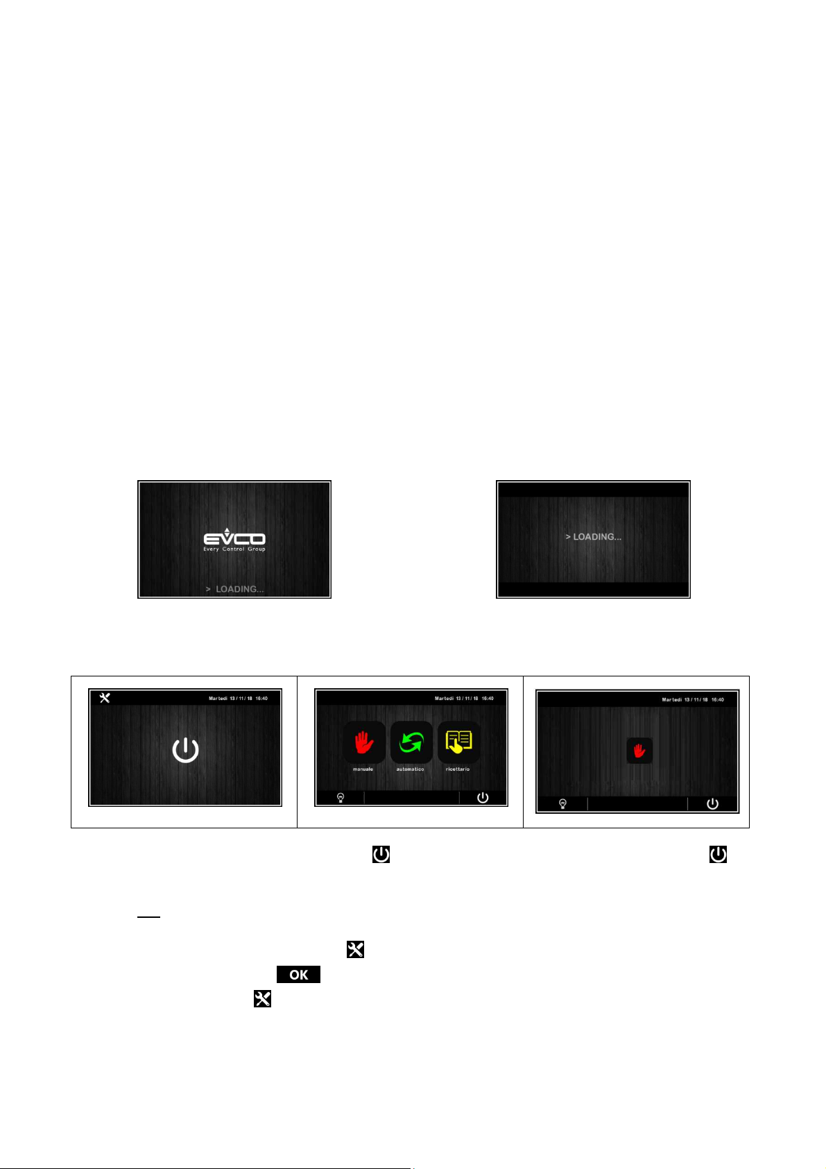
On/stand
-
by screen
Home
screen with E17=0
Home
screen with
E17=1
3 FIRST-TIME USE
3.1 Operating modes
The controller has the following operating modes:
- “off” (no power to the device);
- “stand-by” (the device is powered but switched off);
- “on” (the device is powered, switched on and awaiting start-up of an operating cycle);
- “run” (the device is powered, switched on and running an operating cycle).
Terminology: “switch on the device” means moving from “stand-by” to “on” mode and “switch off the device” means moving from “on”
to “stand-by” mode.
If there is a power failure, when power is restored the device will return to the mode set before the failure.
3.2 Operating the device
Follow these instructions to operate the device.
1. Install the device as shown in section 2 “MEASUREMENTS AND INSTALLATION”, taking all the precautions mentioned in
paragraph 2.6 “Installation precautions”.
2. Make the electrical connection as shown in sectionErrore. L'origine riferimento non è stata trovata. “ELECTRICAL
CONNECTION”.
3.
Connect the power supply to the device:if parameter E9 is set at 1 (default), the device will show the EVCO splash screen
for 10 seconds; if the parameter is set at 0, a system loading screen will be shown:
E9=1
E9=0
Once loading is complete, the device will display the mode it was in before being powered down:
- On/stand-by screen, press the central area to move to the Home screen;
- the Home screen.
Only manual
To switch the device on, press the central key on the On/stand-by screen; to switch the device off, press the key
on the lower part of the Home screen.
N.B. If the power supply has been cut off long enough to cause a clock error (RTC alarm), it will be necessary to reset the
day and time.
4. When switching on from the settings key on the On/stand-by screen, enter the SET DATE/TIME menu, touch the data
to change and confirm with .
5. From the settings key on the On/stand-by screen, enter the SERVICE menu and from here the PARAMETERS menu.
Enter the password -19 and configure the device as you wish in the order in which the parameters are listed in the table
below. Then check that the remaining parameters have been set in a consistent way. See later sections and in particular
the section PARAMETERS.
page 14 of 56

EVCO S.p.A. Vcolor 539 M & L | Installer manual ver. 2.0 | Code 144VC539E204
4 NAVIGATION
4.1 Initial information
Navigating the menus is intuitive, based on touch technology.
- To enter into a procedure, touch the menu or the corresponding icon.
- To exit the procedure and, in general, to return to the previous level, press the Back key.
- To scroll up and down a menu, use the and keys.
- To confirm the settings and/or changes, press the key.
- To start up a cycle, press .
- To interrupt a cycle, hold down for at least 4 seconds.
- To regulate a setting, use the – and + keys or press and drag the relevant bar.
- To silence the buzzer, touch any key while it is sounding. If the buzzer is sounding for the end of an automatic cycle or
because the pre-cooling temperature has been reached, the buzzer will be deactivated automatically after the number of
seconds set by parameter E11 (unless it is silenced manually).
4.2 Home screen
The Home screen is the departure point for navigating the user interface.
The Home screen displays the functions enabled, the date and the time.
All the end user’s selections start from the Home screen.
The 4 interactive keys grant access to the following functions:
select, set and start up a manual conservation cycle of infinite duration
MANUAL
AUTOMATIC
RECIPE BOOK
select, set and start up a complete automatic aging cycle
select and/or change automatic aging cycles saved in the memory
page 15 of 56

EVCO S.p.A. Vcolor 539 M & L | Installer manual ver. 2.0 | Code 144VC539E204
4.3 Run screen
Once a manual or automatic cycle has been started up, the Run screen will appear for the type of cycle selected.
MANUAL
AUTOMATIC
4.3.1 Regulator status icons
While a manual or automatic cycle is being run, the status of the principal loads is displayed as icons on the upper part of the screen.
The table below gives their description when switched on:
compressor active
heating active
heating control not active
fans working and fan speed (LO, HI speed or speed%)
defrosting in progress
humidification in progress
dehumidification in progress
humidity control not active
alarm in progress
page 16 of 56

EVCO S.p.A. Vcolor 539 M & L | Installer manual ver. 2.0 | Code 144VC539E204
4.3.2 Function keys
While a manual or automatic cycle is being run, the lower part of the screen displays the function keys, which are as follows.
switch light on/off
access the modify working setpoint/set cycle pages and the service screen
manual activation of rest cycle
manual activation of smoking cycle (presence can be activated/deactivated from parameter)
manual activation of air change cycle
manual activation of sterilisation cycle (presence can be activated/deactivated from parameter), as an
UV
alternative to oxygenation
manual activation of oxygenation cycle (presence can be activated/deactivated from parameter), as an
alternative to sterilisation
manual activation of defrosting cycle (presence can be activated/deactivated from parameter)
saving and modifying programs and operation data (according to the menu)
4.4 Screen saver
After a period of inactivity set by parameter E8 (from 1 to 240 minutes), the Run screen will switch to the screen saver showing the
values detected by the probes in use. This function can be disabled by setting parameter E8 to 0.
Just touch the screen to exit the screen saver. When an alarm is in progress, the Run screen will be restored.
Screen saver with manual cycle
Screen saver with automatic cycle
page 17 of 56

EVCO S.p.A. Vcolor 539 M & L | Installer manual ver. 2.0 | Code 144VC539E204
4.5 Settings screen
The settings key on the On/Stand-by screen grants access to the Set-up screen with the relevant function menu (for the
INPUTS/OUTPUTS STATUS function, data are only displayed). To access the various procedures, touch the screen near the
information/function required. The following screen is displayed:
If the heat pump function is enabled with E16=1 there will also be the setting "MACHINE CONFIGURATION" for matrix valve settings
(use password -19).
If parameter E12 is set at 1, the screen will also display the configuration details for the serial control humidifier.
4.5.1 Service
This option gives access to the following menu:
REGISTRATIONS SET-UP
This enables selection of the variables to be recorded for the HACCP history.
RESTORE FACTORY DATA
Touching on this option grants access to the following password-protected functions (149):
- delete records
- restore default parameters
- delete recipes
INTERNAL PARAMETERS
Touching on this option grants access to the password-protected parameter configuration (-19); to configure the parameter
appropriately, consult the list in the section PARAMETERS.
page 18 of 56

EVCO S.p.A. Vcolor 539 M & L | Installer manual ver. 2.0 | Code 144VC539E204
5 AN OVERVIEW OF THE FUNCTIONS
5.1 Automatic and manual cycles
The controller provides complete control for food processing cabinets or rooms for different types of products such as meat,
charcuterie, cheese and other types of product.
After a modification the settings will be saved provided that:
• an immediate START
• pressure on button saving data if the start is not immediate. Note: pressure on button "<" without
saving data will cancel the modifications.
5.2 Settable features for each phase
An automatic aging cycle can consist of a maximum of 30 different sequential phases, for each of which the user can set the following
features:
PHASE 01/30
Manual / Program name
Values
Temperature
Humidity
Ventilation
Duration
30d16h24'
25
60
50
°C
%
%
Interval
Duration
Delay
Days
Rest
12h30'
25'
6h35'
5d
Air exchange
Interval
5.2.1 Management of temperature, humidity, ventilation speed, duration
Regulation of temperature and humidity is carried out in the neutral zone. The resolution of the setpoint setting and the temperature
reading is 0.1°C, while the resolution of the setting and the humidity reading is 1 %RH.
Heating control can be deactivated by the user for the whole duration of the cycle in progress using the general cycle settings.
Humidity control can be deactivated by the user for some phases: by setting humidity under 0%, the "OFF" value or "humidity control
deactivated for the phase in progress" will be set (the icon will appear on the display, showing humidity control is not active).
The ventilation, depending on the type chosen by the OEM, may be SINGLE SPEED (in this case it cannot be regulated by the end
user), DOUBLE SPEED (in this case the user can select LOW or HIGH speed) or modulating through the external phase cutting module
EVDFAN1 (in this case the user can select the speed from the minimum settable by the user to 100%).
Cycle duration can be set from 0 minutes to 30days23h59' with a resolution of 1 minute.
By setting the cycle duration to INF (the equivalent of value 0), the phase will have infinite duration and no following phases will ever
be carried out.
10d00h00' 30'
Duration
page 19 of 56

EVCO S.p.A. Vcolor 539 M & L | Installer manual ver. 2.0 | Code 144VC539E204
5.2.2 Air change management
During the aging process, the air in the cabinet needs changing periodically to ensure it is always rich in oxygen in order to prevent
smells or impurities which could ruin the product.
The interval and duration of the air change fan are set by the user phase by phase.
For phases in which NO automatic air change is required (only manual), just set the activation interval to MANUAL (the equivalent of 0).
If the user also wishes to deactivate the MANUAL air change, just set the air change duration to OFF (the equivalent of 0) for the
desired phase.
5.2.3 Management of product rest intervals
During the aging process, products need frequent and long periods of complete rest, when the equipment does not regulate either the
temperature, humidity or ventilation inside the chamber.
During a rest phase, the only load that can be activated is the recirculation fan and this can be done either automatically or manually
(loads which do not concern regulation, such as light, obviously remain on or can be activated).
Product rest periods can be set by the user, phase by phase, in the following way:
- interval: how often the rest period takes place
- duration: how long the rest period lasts
- delay: how long after the beginning of the phase the first rest interval begins
- days: once the initial delay has elapsed, how many days the rest periods are repeated for, with the established interval and duration.
By setting the interval to MANUAL (the equivalent of 0), the rest period will only be manual.
By setting the duration to OFF (the equivalent of 0), manual rest period will also be disabled.
By setting the delay to 0', the rest period will begin immediately at the beginning of the phase.
The number of days can be set from 1 to 30.
5.3 Settable features for the aging cycle
As well as the individual features of each stage, the aging cycle has a number of special features which can be selected/deselected by
the user during the setting phase. These are:
CYCLE
Cabinet
restart
Heating
control
Final
holding
Final air
exchange
5.3.1 Cabinet restart
When the "Cabinet restart” function is enabled at the end of the set aging cycle, a pop-up appears on the display and, by simply
touching it, the same aging cycle is restarted.
The next time an automatic programme is entered, the controller will return to the last cycle carried out which can easily be retrieved
by the user.
5.3.2 Heating control
By enabling/disabling the "Heating control” function, the heaters (and their connected loads) will be activated/deactivated for the whole
duration of the cycle if the cabinet temperature goes below the neutral zone value established.
page 20 of 56

EVCO S.p.A. Vcolor 539 M & L | Installer manual ver. 2.0 | Code 144VC539E204
If heating control is disabled, the icon on the display
will stay on for the duration of the cycle.
5.3.3 Final holding
By enabling/disabling the "Final holding” function, the user decides if, at the end of the final phase in the cycle, the equipment must
maintain the temperature and humidity in the cabinet at the same values of the last phase before the cycle was STOPPED, or if it must
switch off all the regulation loads, losing control of the temperature and humidity.
5.3.4 Final air change
By enabling/disabling the "Final air change” function, the user decides if the equipment must carry out an air change cycle or not at the
end of the final phase of the cycle in progress. A final holding can be set to begin after the air change.
5.4 Other functions
During both automatic and manual aging cycles, a series of functions/loads can be activated manually by the end user to further
process/transform the products.
All these functions are activated/deactivated from parameter, therefore the function activation keys will only appear on the RUN screen
if they have been enabled.
5.4.1 Product sterilisation/oxygenation cycle
This cycle can be activated manually by the user during either an automatic or a manual aging cycle.
Parameter u1 establishes the type of icon to set, depending on the type of load connected: STERILISATION icon or OXYGENATOR icon.
Once the relevant key has been pressed, a pop-up screen will appear which will establish:
a) duration of the function (consisting of a sequence of Ton + Toff; duration in hh:mm with value 0 = UP TO MANUAL STOP)
b) activation time (in seconds)
c) switch-off time (in seconds)
When the switch-off time is set at 0 seconds, the output will be continuously active for the whole duration set by the user.
It is important to save the last value set by the user and repropose it at the next activation request.
The settings default is: duration = MANUAL, Ton = 180sec, Toff = 0sec
The activation of the function lasts for the duration of the cycle: a sterilisation/oxygenation cycle can be activated while an aging cycle
is taking place.
If the aging cycle changes phase, the sterilisation/oxygenation cycle continues.
If the aging cycle goes into the rest or air change phase, the sterilisation/oxygenation cycle is paused.
If the door is opened or there is a defrosting cycle, the sterilisation cycle will be SUSPENDED and will resume when the door is closed or
after the defrosting cycle and when the ventilation is reactivated.
If the aging cycle ends, the sterilisation/oxygenation cycle continues until the end of its counter time or until it is manually deactivated.
The STERILISATION output is only activated when the EVAPORATOR FAN IS ACTIVATED.
Temperature and humidity are regulated regularly. All the other outputs can be activated/deactivated.
The STERILISATION or OXYGENATION key will become one of 3 colours to indicate the activation, deactivation or pausing of the
function/output. They are:
U V U V U V
white icon key = function disabled
green icon key = function enabled and output activated
orange icon key = function enabled and output deactivated
5.4.2 Product smoking cycle
This cycle can be activated manually by the user during either an automatic or a manual aging cycle.
Once the relevant key has been pressed, a pop-up screen will appear which will establish the duration of the function (duration in
hh:mm with value 0 = UP TO MANUAL STOP).
It is important to save the last value set by the user as it will be reproposed at the next activation request.
The settings default is: duration = MANUAL.
The activation of the function lasts for the duration of the cycle: a smoking cycle can be activated while an aging cycle is taking place.
If the aging cycle changes phase, the smoking cycle is stopped.
If the aging cycle goes into the rest or air change phase, the smoking cycle is paused.
page 21 of 56

EVCO S.p.A. Vcolor 539 M & L | Installer manual ver. 2.0 | Code 144VC539E204
If the door is opened or there is a defrosting cycle, the smoking cycle will be SUSPENDED and will resume when the door is closed or
after the defrosting cycle.
If the aging cycle finishes, the smoking cycle is stopped. When the cycle is terminated, it is not possible to launch a smoking cycle.
Temperature and humidity are regulated regularly. All the other outputs can be activated/deactivated.
The SMOKING key will become one of 3 colours to indicate the activation, deactivation or pausing of the function/output. They are:
white icon key = function disabled
green icon key = function enabled and output activated
orange icon key = function enabled and output deactivated
5.4.3 Manual rest cycle
The operation of this cycle is described in the section "Management of product rest intervals". Similarly to what happens in the
sterilisation/oxygenation and smoking cycles (see previous sections), the relative key will become one of 3 colours to indicate the
activation, deactivation or pausing of the function/output.
5.4.4 Manual air change cycle
The operation of this cycle is described in the section "Air change management". Similarly to what happens in the
sterilisation/oxygenation and smoking cycles (see previous sections), the relative key will become one of 3 colours to indicate the
activation, deactivation or pausing of the function/output.
5.4.5 Manual defrosting
Pressing the appropriate key sets off the manual defrosting cycle. There is also an automatic defrosting cycle which is active at intervals
during all the automatic and manual phases. Similarly to what happens in the sterilisation/oxygenation and smoking cycles (see
previous sections), the relative key will become one of 3 colours to indicate the activation, deactivation or pausing of the
function/output.
5.4.6 Light on/off
This manually switches the light on/off. The switching on/off of the light can also be associated with the digital door switch input status.
Similarly to what happens in the sterilisation/oxygenation and smoking cycles (see previous sections), the relative key will become a
different colour to indicate the activation or deactivation of the function/output (without the orange output status “paused").
page 22 of 56

EVCO S.p.A. Vcolor 539 M & L | Installer manual ver. 2.0 | Code 144VC539E204
6 MAIN FUNCTIONS
6.1 Manual cycle
This area grants access to a manual product conservation/aging cycle.
First a setting screen for the values will be displayed (the last values set for a manual cycle will be given) and, once they have been
confirmed, the manual cycle will start.
After a modification the settings will be saved provided that:
• an immediate START
• pressure on button saving data if the start is not immediate. Note: pressure on button "<" without
saving data will cancel the modifications.
When setting a manual cycle, the "cabinet restart", "final holding", "final air change" and "duration" functions are disabled and cannot
be enabled.
The following screen appears during the manual cycle.
The top bar indicates the status of the main regulation outputs/status (hot / cold / humidification / dehumidification / ventilation /
defrosting status), any alarm in progress (an alarm icon is always given with the description) and the current time-date.
At the top, above the temperature, the word AGING is displayed every 5 sec (if in progress), alternating with the name of the special
cycle in progress. The count-up of the elapsed time from the beginning of the manual cycle will be shown.
By pressing the key or the whole area of the T and RH display (with a resolution of 0.1°C for the temperature), the setpoint
settings screen for the cycle in progress will appear.
If the pH value is enabled from parameter, it is shown in read-only form (to two decimal points) under the relative humidity value.
The area under the temperature indicates:
- the remaining time needed to finish the "special cycle" in progress. Special cycles are: rest cycle, air change cycle, smoking cycle,
sterilisation/oxygenation cycle.
- the type of cycle in progress (manual / automatic / name of programme), which may be replaced by the code of an alarm if in
progress.
page 23 of 56

EVCO S.p.A. Vcolor 539 M & L | Installer manual ver. 2.0 | Code 144VC539E204
N.B.: duration settings cannot be made in the manual cycle, it can only be stopped manually by pressing the key .
6.2 Automatic cycle
6.2.1 Start-up and interruption of an automatic cycle
This area grants access to the following screen where a complete aging cycle can be set, phase by phase:
The automatic cycle starts up when the area is pressed and it terminates automatically at the end of the last set phase, at
which time a buzzer sounds.
The cycle can be interrupted manually during any phase by holding the key down for 4 seconds.
N.B.: the final holding phase is optional (it must be enabled during the general set-up of the cycle) and duration settings cannot
be made in it, so if it is enabled, it can only be stopped manually by pressing the key .
page 24 of 56

EVCO S.p.A. Vcolor 539 M & L | Installer manual ver. 2.0 | Code 144VC539E204
6.2.2 Setting/Making changes to an automatic cycle
Before starting up a cycle, it is possible to consult and modify the settings of each of the stages in the aging cycle.
Once OK has been pressed each time to confirm the changes, these will be saved and used as the settings for the automatic cycle
which is started up:
• by pressing the area
• saving with button
• premendo the modifications will not be saved unless when starting the cycle.
The CYCLE END icon is displayed on the bottom left of the screen: it indicates the day and time for the end of the aging cycle,
which is the sum of times set for each individual phase. The date and time of the end of the cycle have no significance as far as the
programme being set is concerned, they are just a reference for the user.
6.2.3 Saving an automatic cycle
To save the set cycle before it is started up, press the icon at the top left of the screen: scroll through the pages of the recipe book
with the list of recipes using the or keys and choose the desired position in which to save the recipe, giving it a new name
or overwriting an existing recipe. When the operation has been completed, press the key to confirm.
6.3 Recipe book
This area grants access to the MY RECIPES screen listing the automatic/manual aging cycles saved with the name by the user, following
the procedure described in the previous section 6.2.3. Users can save up to 10 recipes.
Press the name of the required recipe to gain direct access to the automatic cycle start-up page, from which it is possible to run a cycle
or enter the various phases to change the settings and to create a new recipe from it, which can also overwrite an existing recipe or
save it with a different name (see section 6.2.3).
page 25 of 56

EVCO S.p.A. Vcolor 539 M & L | Installer manual ver. 2.0 | Code 144VC539E204
N.B.: It is not possible to use dashes in memory names and when such a recipe on the list is pressed there will be no effect.
page 26 of 56

EVCO S.p.A. Vcolor 539 M & L | Installer manual ver. 2.0 | Code 144VC539E204
7 REGULATIONS
7.1 Temperature regulation
Temperature regulation for all phases of the equipment is in the neutral zone in which two relative values are set one above and one
below the temperature setpoint, thus creating a zone inside which the loads for heating and cooling are not activated.
When the temperature rises above the neutral zone value beyond the threshold set by rC0 (cooling differential), the cooling loads are
activated until the temperature returns to the neutral zone value.
Similarly, when the temperature falls below the neutral zone value beyond the threshold set by rH0 (heating differential), the heating
loads are activated until the temperature returns to the neutral zone value.
7.1.1 Generating cooling
Cooling is generated by the refrigeration circuit installed in the equipment.
When cooling is required, the compressor output and the pump-down solenoid valve output (if enabled) are activated.
The evaporator fan operates continuously or in parallel with the compressor, according to how the parameters have been configured for
each phase and on the basis of the speed set for the phase in progress (single speed, double speed or proportional by the external
phase cutting module).
7.1.2 Generating heat
Heat is generated by a heater.
When heating is required, the heater output is activated, with the possibility of running a duty switch on/off cycle (set by parameters
rH6 and rH7), so as to limit the heating power if a very powerful heater is being used and thus avoid the cabinet overheating.
The evaporator fan operates continuously or in parallel with the heater output and on the basis of the speed set for the phase in
progress (single speed, double speed or proportional by the external phase cutting module).
For certain types of aging cycles, the end user can disable the heating control in the cabinet completely when entering the settings for
the cycle.
7.2 TEMPERATURE PRIORITY
If parameter "rU4=1" and the temperature goes outside the control band, the regulator stops dehumidifying using the compressor, in
order that the temperature can getthe SETPOINT, before dehumidifying again.
The minimum cabinet threshold temperature for humidity regulation is parameter rU14.
page 27 of 56

EVCO S.p.A. Vcolor 539 M & L | Installer manual ver. 2.0 | Code 144VC539E204
7.3 Humidity regulation
In all phases where this is required, the humidity is regulated with a humidity transducer enabled in the neutral zone in which two
values are set, one above and one below the humidity setpoint, thus creating a zone inside which the loads for humidification and
dehumidification are not activated.
When the humidity rises above the neutral zone value beyond the threshold set by rU5 (dehumidification differential), the
dehumidifying loads are activated and they remain active until the humidity returns to the neutral zone value.
Similarly, when the humidity falls below the neutral zone value beyond the threshold set by rU8 (humidification differential), the
humidifying loads are activated proportionally and they remain active until the humidity returns to the neutral zone value.
If the humidity setpoint is set to OFF for one phase, humidity control is disabled for the entire phase (the humidity value in the cabinet
will be displayed however).
NB.: for managing humidity without a transducer, see section 8.7.
7.3.1 Humidification management
Humidification is managed by two different loads: a humidity generator output and a humidifier output (if enabled by parameter).
If parameter E12 is set at 0, the steam generator output remains active during the phases for which humidification management is
required. The humidifier output, on the other hand, is only activated when the humidity value inside the cabinet falls below the neutral
zone value (set by parameter rU9) beyond the threshold set by parameter rU8 (humidification differential). The humidifier output
activation time percentage is proportional to the humidity value compared to the proportional humidification band value set by
parameter rU10. The activation/deactivation cycle time of the humidification output is set by parameter rU11, while the duration of
activation is calculated on the basis of the time set by rU12.
page 28 of 56

EVCO S.p.A. Vcolor 539 M & L | Installer manual ver. 2.0 | Code 144VC539E204
If parameter E12 is set at 1, the generator output will only be active when the humidity falls below the neutral zone value (set by
parameter rU9) beyond the threshold set by rU8 (humidification differential). However, the humidifier output is activated in on/off
cycles when required, always starting at the off time, to allow the steam generator to be ready to generate humidity.
7.3.2 Dehumidification management
Dehumidification can be managed in two different ways: using an extractor fan/dehumidifier (u4=0) or by activating the refrigeration
plant (u4=1).
When being managed by an extractor fan/dehumidifier, the output will be activated when the humidity rises above the dehumidification
neutral zone value (parameter rU6) beyond the threshold set by parameter rU5 (dehumidification differential) and it is deactivated
when the humidity returns to within the dehumidification neutral zone value.
The compressor works in the same way if pump-down solenoid valve management is not enabled (parameter u1=1).
If pump-down solenoid valve management is enabled (parameter u1=0), there will be a first attempt at dehumidification by activating
the solenoid valve for a time set by parameter rU7, in an attempt to make use of the high pressure generated during pump-down when
the compressor is switched off. Once this time has elapsed, the compressor output will also be activated if further dehumidification is
required.
Once the humidity returns to within the dehumidification neutral zone value, the pump-down solenoid valve will be deactivated, after
which the compressor will be deactivated by the pump-down algorithm.
page 29 of 56

EVCO S.p.A. Vcolor 539 M & L | Installer manual ver. 2.0 | Code 144VC539E204
8 LOAD MANAGEMENT
8.1 Compressor management
Activation of the compressor depends on the length of the delay between two switch-ons (parameter C1), on the minimum duration of
the compressor-off time (parameter C2), on the delayed switch-on of the compressor from the device power-on (parameter C0) and on
the minimum duration of the compressor-on time (parameter C3).
The compressor can also be active during a hot gas defrost (parameter d1 = 1). In this situation, in order for the defrost to start, the
compressor must be active for at least the time set by parameter d15.
The compressor can also be used for dehumidification, for more details see section 8.8.2.
The compressor switch-off is managed differently if management of the pump-down solenoid valve is required. For more details see the
next section.
8.2 Pump-down management
If an output is configured as a pump-down solenoid valve, the controller will manage the interaction between the compressor output
and the solenoid valve output as follows:
With timed pump-down (parameter i6 = 0 or 1):
When the compressor is activated, the pump-down solenoid valve will be activated in parallel.
The deactivation of the compressor will be preceded by deactivation of the pump-down solenoid valve. After the time set by u2 the
compressor output will also be deactivated.
With pump-down managed by digital input LP (parameter i6 = 2):
When the compressor is activated, the pump-down solenoid valve will be activated in parallel.
The deactivation of the compressor will be preceded by deactivation of the pump-down solenoid valve. The compressor will then be
switched off by the action of digital input LP.
If there is no action of the digital input LP within the maximum time set by u2, the compressor will be deactivated and the PUMP DOWN
alarm will be activated. Any HIGH PRESSURE alarm will turn off the compressor regardless of the pump-down management.
If pump-down is managed by digital input LP, each time the compressor and solenoid valve output are switched on, a re-arm time will
be loaded for digital input LP (parameter i9). When the compressor is switched off, the status of digital input LP will not be affected.
8.3 Evaporator fan management
The evaporator fan is managed based on parameter F0:
- in single speed mode by a digital output
- in double speed mode by two HIGH SPEED and LOW SPEED digital outputs
- with proportional speed set by the user by the analogue output PWM (to be teamed with the phase cutting module EVDFAN1)
The evaporator fan can be configured during the phases of an automatic cycle to work continuously or in parallel with the regulation
output, that being in parallel with the compressor, heater, humidification and dehumidification. The way it behaves is set by parameter
F1.
It is possible to select a different operating mode for the fan for the final holding phase and during manual operation (parameter F4).
It is also possible to set a regulation output delay at the fan deactivation using parameter F13 and a duty-cycle with a cycle time and
On time set by parameters F14 and F15 during deactivation of the main load. If parameters F14 and F15 are set to zero, there will be
no activation.
The duty cycle set by parameters F14 and F15 is also valid during THE PRODUCT REST PHASES, to prevent stratification of the air in
the cabinet.
During refrigeration phases, the fan will only be active when the evaporator temperature is below the value set by parameter F25.
If the evaporator fan is being managed by a two-speed fan output (HIGH-LOW) or analogue output PWM, it will also be possible to set
the fan speed for each phase.
When it is managed by PWM, when the fan is switched on the controller manages its speed (F21) and a start-up time (F22). When the
start-up phase ends, the fan speed will keep to the speed set for the phase in progress, compensated between parameters F23 and F24
that set the minimum and maximum fan speed respectively.
During a defrost cycle the fan is in OFF mode. At the end of the defrost cycle, the evaporator fan will remain off for the drip time set by
parameter d7 and the subsequent evaporator fan-stop time set by parameter F12.
Evaporator fan calibration procedure managed by the TDF module:
page 30 of 56

EVCO S.p.A. Vcolor 539 M & L | Installer manual ver. 2.0 | Code 144VC539E204
To adapt the phase-cutting regulation (T.D.F.) to all types of 230 VAC single-phase motors, a manual evaporator fan calibration
procedure is recommended.
1. Set F23 at 0% and F24 at 100%.
2. Carry out a manual cycle and vary the fan speed, check the minimum percentage below which the fan switches off and
the maximum percentage above which the fan runs at maximum.
3. Set these values for F23 and F24 respectively.
8.3.1 MODULATING VENTILATION ACCORDING TO THE STATUS
If F5=1 it is possible to associate a specific speed to the ventilation, according to the regulation status:
REGULATION STATUS Value % ventilation output
Cool request F6
Heat request F7
Pause regulation (no heating, no cooling, no
humidification, no dehumidification)
Humidification
Humidification F10
De- Humidification F11
F8
F9=0 set fix value F10
F9=1 modulating ramp between values
the humidity value to the threshold ru9 (in pause F8)
and the speed value F10 to the threshold rU8
8.4 Defrost management
Defrost is active during all the operating phases (both automatic and manual cycles) and can be either automatic (time intervals) or
manual. Manual defrost can be activated by accessing the relevant menu on the On/stand-by screen by pressing the key or during
a cycle, by the MANUAL DEFROSTING key on the lower part of the screen.
Depending on the value of parameter d1, the machine will perform either electric or hot gas defrost cycles.
If the evaporator probe is enabled (parameter P3=1), the defrost will end when it reaches the end-of-defrost temperature (parameter
d2) within a maximum time interval set by parameter d3. If the evaporator probe is not enabled (P3=0) or if it is out of order, defrost
will end at the time set by parameter d3.
At the end of a defrost cycle, the controller will allocate a drip time (d7) during which all the regulation outputs will be switched off.
When the dripping time finishes, the refrigeration plant will begin working again but activation of the evaporator fan will be further
delayed by the time set by parameter F12.
If a hot gas defrost is being carried out, in order for the defrost to start, the compressor must be activated for at least the time set by
parameter d15.
8.5 Heater management
When heat is required, the heater output will be activated, also making it possible to manage a switch-on and off duty-cycle controlled
by parameters rH6 and rH7.
8.6 Steam generator output management
Management of the steam generator load (if enabled) depends on the setting of parameter E12.
If E12=0: the steam generator output remains active during all the phases in which cabinet humidification is required.
If E12=1: the steam generator output is active when the setting requires humidification
8.7 Humidifier output management
The humidifier load (if enabled) can be managed with or without the use of a humidity transducer (parameter rU0) and it varies
according to the type of humidifier selected (parameter E12).
page 31 of 56

EVCO S.p.A. Vcolor 539 M & L | Installer manual ver. 2.0 | Code 144VC539E204
8.7.1 Managing the humidifier output without a transducer (rU0 = 1, E12 = 0 or 1)
In this situation, the humidifier output will remain active for a duty-cycle that varies according to the humidity setpoint for the phase in
progress.
The output activation and deactivation duration is set by parameter rU2 (humidification cycle time) and the maximum humidification
time needed to obtain 100% humidity within the cabinet (rU3).
The humidification switch-on/off times will be proportional on the basis of the humidity setpoint percentage according to parameter rU3,
and they will be repeated for every cycle time set by rU2.
8.7.2 Managing the humidifier output with a transducer and a humidifier with a steamer (rU0 = 0, E12 =
0)
The humidifier output is activated when the humidity value inside the cabinet falls below the neutral zone value (rU9) beyond the
threshold set by the humidification differential (rU8).
The duration of the humidifier output activation is proportional to the humidity value compared to the proportional humidification band
value set by parameter rU10.
Parameter rU11 sets the cycle time, while parameter rU12 represents the time base used to calculate the output activation duration.
8.7.3 Managing the humidifier output with a transducer and an instant generation humidifier (rU0 = 0,
E12 = 1)
The humidifier output is activated when the humidity value inside the cabinet falls below the neutral zone value (rU9) beyond the
threshold set by the humidification differential (rU8) performing off/on cycles, the duration being set by parameters rU15 and rU16. The
count always starts from the off time.
8.8 Dehumidification management
Dehumidification management is only active when humidity is managed by a humidity transducer (rU0 = 0 or 2).
Dehumidification can be managed in two different ways: using an extractor fan (parameter u4) or by activating the refrigeration plant
(compressor and pump-down solenoid valve if present).
8.8.1 Management using an extractor fan/dehumidifier
When managed by an extractor fan/dehumidifier, the output will be activated when the humidity rises above the dehumidification
neutral zone value (rU6) plus the differential value (rU5) and it is deactivated when the humidity returns to within the dehumidification
neutral zone value.
8.8.2 Management by activating the refrigeration plant
If, however, pump-down solenoid valve management is enabled, there will be a first attempt at dehumidification by activating the
pump-down solenoid valve (to make use of the high pressure generated when the compressor is switched off), for a time period set by
rU7. After this time has elapsed, the compressor output will be activated.
Once the humidity returns to within the dehumidification neutral zone value, the pump-down solenoid valve will be deactivated, after
which the compressor will be deactivated by the pump-down algorithm.
If the pump-down solenoid valve management is not enabled, the compressor will be activated and will stay on until the humidity
returns to within the dehumidification neutral zone value.
8.9 Condenser fan management
If the condenser probe is enabled (parameter P4 = 1), the condenser fan will activate when the condenser temperature rises above the
value of parameter F16 plus the differential value (F16 + 2.0 °C / 4 °F), regardless of compressor status.
The condenser fan will switch off when the condenser temperature falls below the value of parameter F16.
If the condenser probe is disabled (parameter P4 = 0), the condenser fan will activate in parallel with the compressor, while
deactivation will be delayed for the time set by parameter F17.
During CONDENSER OVERHEAT or COMPRESSOR LOCKED alarm, the condenser fan will stay on.
During defrost the fans will be switched off.
8.10 Cabinet light management
The cabinet light will switch-on/off by opening/closing the door or by pressing the key while manual and/or automatic cycles are
being carried out.
page 32 of 56

EVCO S.p.A. Vcolor 539 M & L | Installer manual ver. 2.0 | Code 144VC539E204
8.11 Air change fan management
The air change fan can be activated automatically and manually depending on the user’s choice when setting the working cycle.
For phases in which NO automatic air change is required (only manual), the activation interval should be set to MANUAL (the equivalent
of 0).
If the user also wishes to deactivate the MANUAL air change, the air change duration should be set to OFF (the equivalent of 0) for the
desired phase.
8.12 Sterilisation/oxygenation management
The manufacturer parameter "u1" enables the output to be associated with the STERILISER or OXYGENATOR load (with the relevant
icon).
By pressing the relevant key, the end user can manually activate the load, establishing the:
a) duration of the function (consisting of a sequence of Ton + Toff; duration in hh:mm with value 0 = UP TO
MANUAL STOP)
b) activation time (Ton in seconds)
c) switch-off time (Toff in seconds); when the switch-off time is set to 0 seconds, the output will be continuously active for
the whole duration set by the user).
If the aging cycle goes into the rest or air change phase, the sterilisation/oxygenation cycle is paused.
If the door is opened, if there is a defrosting cycle or if the evaporator fan is deactivated, the sterilisation cycle will be SUSPENDED and
will resume when the evaporator fan is reactivated.
If the aging cycle finishes, the sterilisation/oxygenation cycle is stopped.
The STERILISATION output is only activated when the EVAPORATOR FAN IS ACTIVATED.
Temperature and humidity are regulated regularly. All the other outputs can be activated/deactivated.
8.13 Smoker management
By pressing the relevant key, the end user can manually activate the load, establishing the duration of the function (duration in hh:mm
with value 0 = UP TO MANUAL STOP)
If the aging cycle changes phase, the smoking cycle is stopped. If the aging cycle goes into the rest or air change phase, the smoking
cycle is paused.
If the door is opened or there is a defrosting cycle, the smoking cycle will be SUSPENDED and will resume when the door is closed after
the defrosting cycle.
If the aging cycle finishes, the smoking cycle is stopped. When the cycle is terminated, it is not possible to launch a smoking cycle.
Temperature and humidity are regulated regularly. All the other outputs can be activated/deactivated.
8.14 Alarm output management
The alarm output is activated/deactivated according to the value of parameter A5 when there is an alarm situation. It is
activated/deactivated once the alarm situation has disappeared.
page 33 of 56

EVCO S.p.A. Vcolor 539 M & L | Installer manual ver. 2.0 | Code 144VC539E204
9 MANAGEMENT OF EQUIPMENT WITH HEAT PUMP
9.1 Food processing rooms with heat pump
The controller has a special operating mode for equipment with a heat pump, which can be enabled by setting parameter
E16 = 1
When the heat pump mode is enabled, the controller always uses the refrigeration plant for cabinet cooling (and dehumidification)
requests, whereas it uses the coupled compressor + 4-way valve for cabinet heating requests.
Parameter u3 establishes the delay between the activation/deactivation of the 4-way valve in relation to the deactivation/activation of
the compressor.
If the operating mode is enabled with the heat pump in the SERVICE menu, a new menu is enabled called "EQUIPMENT
CONFIGURATION" (protected by password -19) which contains the following configuration matrix:
Using the matrix, it is possible to decide the operating logic of up to 7 different VALVES (from V1 to V7) according to the different
machine status during the aging cycle.
EXAMPLE
Valve 1 is:
ON during a cooling request
OFF during a heating request
OFF during a dehumidification request
OFF during a humidification request
ON during a defrosting request
ON during a special air change cycle
OFF during a special rest cycle
OFF during a pause between two phases (new parameter to insert)
OFF when both the temperature and humidity values are within the neutral zone value.
If E16 = 1, each of the VALVES from V1 to V7 can be associated with a relay output from K1 to K13.
If the operating mode is enabled with the heat pump, the parameters from u01c to u13c increase their maximum settable value from
17 to 23, including the 7 CONFIGURABLE VALVES.
Load associated with output K1
0 = compressor
1 = cabinet light
2 = humidification
3 = air change
4 = heater
u01c 0 15 (23) - - - - 0
5 = defrosting
6 = pump-down solenoid valve
7 = condenser fan
8 = alarm
9 = steriliser/oxygenator
10 = smoker
11 = steam generator
12 = dehumidification
page 34 of 56

EVCO S.p.A. Vcolor 539 M & L | Installer manual ver. 2.0 | Code 144VC539E204
13 = evaporator fan
14 = low speed evaporator fan
15 = high speed evaporator fan
16 = 4-way valve
17 = Valve V1
18 = Valve V2
19 = Valve V3
20 = Valve V4
21 = Valve V5
22 = Valve V6
23 = Valve V7
page 35 of 56

EVCO S.p.A. Vcolor 539 M & L | Installer manual ver. 2.0 | Code 144VC539E204
10 USB PORT MANAGEMENT
The USB port provides the following functions:
- download to a USB flash drive the data relating to the cycles performed (HACCP history)
- download to a USB flash drive the recipes saved in the controller
- download to a USB flash drive the parameters saved in the controller
- upload to the controller the recipes in the USB flash drive
- upload to the controller the parameters in the USB flash drive
Before inserting the flash drive into the USB port on the machine, switch to the On/stand-by screen and the menu shown below will
appear.
If the heat pump management is active E16=1 there will also be two settings:
VALVE SETUP DOWNLOAD To save the matrix map into an USB flash key
VALVE SETUP UPLOAD To load the matrix map from an USB flash key
To download historical data select the date to begin downloading HACCP data.
page 36 of 56

EVCO S.p.A. Vcolor 539 M & L | Installer manual ver. 2.0 | Code 144VC539E204
11 EPOCA CLOUD PLATFORM
EPoCA is a remote monitoring system based on a cloud platform. All that is needed is a simple onsite Wi-Fi internet connection to
enable the controller, using EVlink Wi-Fi module, to connect to the cloud system, making it possible to remotely manage equipment
from a PC, tablet or smartphone.
The responsive design and the graphic interface conceived to provide a pleasant user experience make EPoCA a ready-to-use solution
for easily accessible monitoring operations, even for entry-level users, while offering all the typical functions of professional platforms.
With appropriate protection measures for access and data, the system makes it possible for one or more enabled users to operate
remotely on the unit to configure its parameters, view HACCP data (also in graphic form) and to download records in the most popular
formats, such as XLSX, CSV and PDF. The functions playing a key role include alarm warnings sent automatically by the system to
selected e-mail addresses.
Schematic diagram:
For more details on the EVlink Wi-Fi module and on the EPoCA cloud platform, please check out the "EPoCA" manual in our website
www.evco.it.
page 37 of 56

EVCO S.p.A. Vcolor 539 M & L | Installer manual ver. 2.0 | Code 144VC539E204
12 PARAMETERS
The table below describes the configuration parameters of the device.
Par. Min Max Unit Default Analogue inputs
CA1 -25 25 °C 0 cabinet probe offset
CA2 -25 25 °C 0 evaporator probe offset
CA3 -25 25 °C 0 condenser probe offset
CA4 -25 25 % r.H. 0 humidity probe offset
CA5 -5.00 5.00 --- 0.00 pH probe offset
type of probe
P0 0 1 - - - - 1
P2 0 1 - - - - 0
P3 0 1 - - - - 1
0 = PTC
1 = NTC
temperature measurement unit
0 = °C
1 = °F
NB.: variations to the value of parameter P2 are only effective after
the board has been reset
enable evaporator probe
0 = disabled
1 = enabled
enable condenser probe
P4 0 1 - - - - 0
P5 0 60 min 15
P6 - - - - - - - - - - - - - - - - unused
P7 0 P8 % r.H. 0
P8 P7 100 % r.H. 100
P9 0 1 - - - - 0
P10 -5.00 P11 % r.H. 0.00 lower calibration limit of the pH transducer (corresponding to 4 mA)
P11 P10 10.00 % r.H. 7.00 upper calibration limit of the pH transducer (corresponding to 20 mA)
Par. Min Max Unit Default Cooling regulator
rC0 1 15 °C 2 cooling regulation differential
rC1 -99 99 °C -20 minimum setpoint that can be set
0 = disabled
1 = enabled
duration of the power failure above which the alarm “power failure” is
displayed
lower calibration limit of the humidity transducer (corresponding to 4
mA)
upper calibration limit of the humidity transducer (corresponding to 20
mA)
enable pH probe (only if rU0 = 1 or 2)
0 = disabled
1 = enabled
rC2 -99 99 °C 20 maximum setpoint that can be set
rC3 0 10 °C 1 cooling neutral zone value
Par. Min Max Unit Default Heating regulator
rH0 1 15 °C 2 heating differential
rH3 0 10 °C 1 neutral zone value
rH6 1 600 s 60 cycle time for heater switch-on if heating is required (see also rH7)
page 38 of 56

EVCO S.p.A. Vcolor 539 M & L | Installer manual ver. 2.0 | Code 144VC539E204
rH7 1 600 s 45 heater switch-on time within the rH6 cycle time
rH8 0 600 min 15 duration pause at beginning of phase
+Par. Min Max Unit Default Humidity regulator
humidity management mode:
0 = with humidity probe 4 -20 mA
rU0 0 2 - - - - 0
1 = without humidity probe, time intervals based on the percentage
set
2 = with humidity probe EVHTP500
rU1 -99 99 °C 0 minimum cabinet temperature for inhibiting humidification control
rU2 1 600 s 60 cycle time for humidifier switch-on (only for rU0 = 1, see also rU3)
rU3 1 600 s 30
humidifier switch-on time rU2 cycle time to generate 100% humidity
in cabinet (only for rU0 = 1, see also rU2)
temperature priority
rU4 0 1 - - - - 0
0= no
1= yes (temperature setpoint is satisfied and then the device controls
the humidity)
rU5 1 100 % r.H. 5 dehumidification differential
rU6 0 100 % r.H. 2 dehumidification neutral zone value
rU7 0 255 s 10 duration of dehumidification attempt with pump-down solenoid valve
rU8 1 100 % r.H. 5 humidification differential
rU9 0 100 % r.H. 2 humidification neutral zone value
rU10 0 50 % r.H. 10 humidification proportional band value (only for E12=0)
rU11 0 255 s 30 cycle time for humidification proportional regulation (only for E12=0)
time base for humidification proportional regulation cycle time (only
rU12 0 1 - - - - 0
for E12=0):
0 = seconds
1 = minutes
rU13 0 100 % 80 maximum humidity setpoint that can be set
rU14 -99 99 °C 0 minimum cabinet temperature for inhibiting dehumidification control
rU15 0 300 s 60 humidifier pause time (only if E12=1)
rU16 0 60 s 3 humidifier activation time (only if E12=1)
Par. Min Max Unit Default Compressor protection
C0 0 240 min 0 compressor switch-on delay from device switch-on
C1 0 240 min 2 delay between two compressor switch-ons
C2 0 240 min 0 minimum compressor-off duration
C3 0 240 s 0 minimum compressor-on duration
C4 0 240 min 0 compressor activation time during dehumidification
C6 0 199 °C 70
C7 0 199 °C 80
condensation temperature above which the condenser overheat alarm
sounds
condensation temperature above which the compressor locked alarm
sounds
C8 0 15 min 1 compressor locked alarm delay
page 39 of 56

EVCO S.p.A. Vcolor 539 M & L | Installer manual ver. 2.0 | Code 144VC539E204
C9 0 999 min 10 time compressor ON during temperature probe error
C10 0 999 min 10 time compressor OFF during temperature probe error
Par. Min Max Unit Default Defrosting
d0 0 99 h 6
automatic defrost interval
0 = defrost at intervals is never repeated
type of defrost
0 = electrical (during defrosting the compressor is switched off, the
d1 0 2 - - - - 0
1 = hot gas (during defrosting the compressor is switched on, the
2 = when cycle is reversed (remember to enable an output as the
d2 -99 99 °C 8
defrost end threshold (evaporator temperature); see also parameter
d3
if parameter P3 is set at 0, defrost duration
d3 0 99 min 30
if parameter P3 is set at 1, maximum defrost duration; see also
parameter d2
0 = defrost is never activated
d5 0 99 min 30 reserved
d7 0 15 min 2
drip time (during dripping the compressor and evaporator fan will
remain off and the defrost output will be deactivated)
defrost output is activated and the evaporator fan switched
off).
defrost output is activated and the evaporator fan is switched
off).
4-way valve and operation as heat pump)
d15 0 99 min 0
minimum consecutive compressor-on duration for starting hot gas
defrost when defrost interval elapses (only if parameter d1 is set at 1)
Par. Min Max Unit Default Temperature alarms
A1 0 99 °C 70
evaporator temperature above which the evaporator high temperature
alarm is activated; see also parameter A2
delay evaporator high temperature alarm
A2 -1 240 min 1
1 = yes
-1 = alarm not enabled
A3 0 99 °C 70
A4 -1 240 min -1
cabinet temperature above which the cabinet high temperature alarm
is activated; see also parameter A4
delay high cabinet temperature alarm
-1 = alarm not enabled
Polarity of alarm relay output
A5 0 1 - - - - 0
0 = NO
1 = NC
Par. Min Max Unit Default Evaporator and condenser fan
Type of evaporator fan management
F0 0 1 - - - - 2
0 = single speed on relay output
1 = double speed (HIGH/LOW) on two relay outputs
2 = variable speed on PWM output and TDF EVFDAN1 module
evaporator fan activity during the aging phases
F1 0 1 - - - - 0
0 = parallel function with the compressor
1 = continuous function
F2 0 1 - - - - 0 temperature and humidity management during special air change
page 40 of 56

EVCO S.p.A. Vcolor 539 M & L | Installer manual ver. 2.0 | Code 144VC539E204
cycles
0 = management T + RH disabled
1 = management T + RH enabled
evaporator fan activity during the final holding phase and during the
F4 0 1 - - - - 0
F5 0 1 - - - - 0
F6 10 100 % 100 Evaporator fan speed in Cooling with "F05=1".
F7 10 100 % 100 Evaporator fan speed in Heating with "F05=1".
F8 0 100 % 0
manual cycle
0 = parallel function with the main loads
1 = continuous function
common or separated fan speed
0= common (the value depends on "Ventilation" and can be changed
for dehumidification using F11).
1= separated with F6/F7/F8/F9/F10/F11.
The fan value is cancelled from the display and can not be changed
(just like when the EVDFAN module is not connected).
The value is loaded according the active function
evaporator fan speed in rest regulation with "F05=1" (when cooling,
heating, humidifying and dehumidifying is not active).
0= not active, stop fan.
evaporator fan mode in humidifying with "F05=1":
F9 0 1 - - - - 0
F10 10 100 50
F11 0 100 % 100
F12 0 15 min 2 fan stop after the drip phase
F13 0 250 s 0 evaporator fan switch-off delay from main load switch-off
F14 1 600 s 0
F15 1 600 s 0
F16 0 99 °C 20
0= normal fix fan with value F10
1= modulating (according to a ramp)
evaporator fan speed in humidifying umidifica
With "F05=1" and "F9=1" the speed depends on the humidity value:
moving from the active speed at the moment of the humidification
request (threshold rU9) to the value F10 (threshold rU8). Uphill or
downhill according to the parameters.
evaporator fan speed
common if F5=0
in dehumidification if F5=1
evaporator fan cycle time with compressor switched off (applies both
during normal operation and during a product rest phase). If set at 0,
cyclical fan switch-on will be deactivated
evaporator fan switch-on time within the F14 cycle time (applies both
during normal operation and a product rest phase)
condenser temperature above which the condenser fan is switched on
(irrespective of the compressor status)
F17 0 240 s 5
F18 0 240 s 15
F19 0 100 % 20 minimum evaporator fan speed that can be set
F20 0 100 % 100 maximum evaporator fan speed that can be set
F21 0 100 % 75 evaporator fan start-up speed
condenser fan switch-off delay from compressor switch-off (only
applies if the condenser probe is disabled)
evaporator fan switch-on delay from when the door is closed, or the
door switch input is deactivated
page 41 of 56

EVCO S.p.A. Vcolor 539 M & L | Installer manual ver. 2.0 | Code 144VC539E204
F22 1 10 s 5 start-up time when the evaporator fan is switched on
F23 0 100 % 35 evaporator fan min. speed calibration value
F24 0 100 % 65 evaporator fan max. speed calibration value
F25 -50 99 °C 1 evaporator temperature below which the evaporator fan is activated
Par. Min Max Unit Default Digital inputs
effect of the door opening, or when the door switch input is activated
0 = no effect
1 = the compressor, evaporator fan and heaters are switched off,
i0 0 2 - - - - 2
the cabinet light is switched on
2 = the evaporator fan and heaters are switched off, the cabinet
light is switched on
If the door is opened, the humidifier, steriliser/oxygenator and smoker
are switched off
door switch input contact type
i1 0 1 - - - - 1
0 = normally open (input active with contact closed)
1 = normally closed (input active with contact open)
i2 -1 120 min 5
i3 0 1 - - - - 1
i4 0 1 - - - - 0
i5 -1 240 s 5
i6 0 3 - - - - 2
door open alarm signal delay
-1 = alarm not signalled
effect caused by activation of the high pressure input
0 = no effect
1 = the compressor and evaporator fan are switched off, the
condenser fan is switched on
high pressure input contact type
0 = normally open (input active with contact closed)
1 = normally closed (input active with contact open)
high pressure alarm signal delay
-1 = alarm not signalled
effect caused by activation of the low pressure input
0 = no effect
1 =ALARM The compressor and evaporator fan are switched off
2 =PUMP-DOWN AND ALARM MANAGEMENT While the compressor is
being switched off, the digital input will act to switch off the
compressor output to end the pump-down phase. During the
activation phases of the refrigeration plant, the digital input
will act to switch off the compressor and evaporator fan.
3 = COMPRESSOR THERMAL SWITCH ALARM The compressor is
switched off
low pressure input contact type
i7 0 1 - - - - 0
0 = normally open (input active with contact closed)
1 = normally closed (input active with contact open)
i8 -1 240 s 10
i9 0 240 s 40
low pressure alarm signal delay
-1 = alarm not signalled
re-arm time for the low pressure switch when the compressor is
switched on (only if i6 = 2)
thermal switch input contact type
i10 0 1 - - - - 0
0 = normally open (input active with contact closed)
1 = normally closed (input active with contact open)
i11 -1 240 s 5 thermal switch alarm signal delay
page 42 of 56

EVCO S.p.A. Vcolor 539 M & L | Installer manual ver. 2.0 | Code 144VC539E204
-1 = alarm not signalled
Par. Min Max Unit Default Digital outputs
Type of icon associated with the steriliser/oxygenator key and load
u1 0 1 - - - - 0
0 = steriliser
1 = oxygenator
if i6 = 0 or 1:
compressor deactivation delay from pump-down valve switch-off
(pump-down being switched off)
u2 0 240 s 90
if i6 = 2:
maximum pump-down duration in compressor switch-off mode
without activating the low pressure input, causing the compressor to
switch off and the pump-down alarm to sound
0 = no alarm signal
u3 0 600 s 15
u4 0 1 - - - - 1
u01c 0 15 (23) - - - - 0
compressor activation/deactivation delay in relation to the 4-way
valve when heat pump is in operation
Dehumidification management type
0 = dehumidifier/extractor fan (with this setting parameters rU5 and
rU6 are relevant)
1 = management by activating the refrigeration plant
Load associated with output K1
0 = compressor
1 = cabinet light
2 = humidification
3 = air change
4 = heater
5 = defrosting
6 = pump-down solenoid valve
7 = condenser fan
8 = alarm
9 = steriliser/oxygenator
10 = smoker
11 = steam generator
12 = dehumidification
13 = evaporator fan
14 = low speed evaporator fan
15 = high speed evaporator fan
16 = 4-way valve
17 = Valve V1
18 = Valve V2
19 = Valve V3
20 = Valve V4
21 = Valve V5
22 = Valve V6
23 = Valve V7
u02c 0 15 (23) - - - - 1 Load associated with output K2 (see u01c)
u03c 0 15 (23) - - - - 2 Load associated with output K3 (see u01c)
u04c 0 15 (23) - - - - 3 Load associated with output K4 (see u01c)
u05c 0 15 (23) - - - - 4 Load associated with output K5 (see u01c)
u06c 0 15 (23) - - - - 8 Load associated with output K6 (see u01c)
u07c 0 15 (23) - - - - 7 Load associated with output K7 (see u01c)
page 43 of 56

EVCO S.p.A. Vcolor 539 M & L | Installer manual ver. 2.0 | Code 144VC539E204
u08c 0 15 (23) - - - - 6 Load associated with output K8 (see u01c)
u09c 0 15 (23) - - - - 5 Load associated with output K9 (see u01c)
u10c 0 15 (23) - - - - 9 Load associated with output K10 (see u01c), only with expansion
u11c 0 15 (23) - - - - 10 Load associated with output K11 (see u01c), only with expansion
u12c 0 15 (23) - - - - 11 Load associated with output K12 (see u01c), only with expansion
u13c 0 15 (23) - - - - 12 Load associated with output K13 (see u01c), only with expansion
Par. Min Max Unit Default
Serial communication (serial port type RS-485 with MODBUS
communication protocol)
L1 1 240 min 10 internal data sampling time
PA1 426 -99 999 - - - - EPoCA level 1 password
PA2 824 -99 999 - - - - EPoCA level 2 password
Serial port connectivity configuration
bLE 1 0 99 - - - -
0 = free
1 = forced for EPoCA
2-99 = EPoCA local network address
LA 1 247 - - - - 247 device address
baud rate
0 = 2,400 baud
Lb 0 3 - - - - 2
1 = 4,800 baud
2 = 9,600 baud
3 = 19,200 baud
parity
LP 0 2 - - - - 2
0 = none
1 = odd
2 = even
Par. Min Max Unit Default Other
E7 -99 99 - - - 0
E8 0 240 min 1
password to unlock screen saver
0 = not enabled
inactivity period for enabling screen-saver
0 = not enabled
display EVCO splash screen at power-on
E9 0 1 - - - - 1
0 = neutral screen
1 = EVCO splash screen
E11 0 120 s 10 duration of buzzer at end
type of humidifier
E12 0 1 - - - - 0
0 = humidifier with steamer
1 = humidifier with instant generation
E13 0 240 min 10
duration of “cycle completed” display
0 = not enabled
E14 - - - - - - - - - - - - - - - - unused
E15 0 1 - - - - 0 Enable 4 relay expansion EVC20P52N9XXX10
E16 0 1 - - - - 0
Enable heat pump operation
0 = disabled
page 44 of 56

EVCO S.p.A. Vcolor 539 M & L | Installer manual ver. 2.0 | Code 144VC539E204
1 = enabled
E17 0 1 - - - - 0
E18 0 1 - - - 0
If set to 1, the only type of defrost possible is with the 4-way valve
Disable programs
0= No
1=Yes
Use matrix valve during dehumidification with compressor
0= 1st column compressor
1= 3rd culumn dehumidification
page 45 of 56

EVCO S.p.A. Vcolor 539 M & L | Installer manual ver. 2.0 | Code 144VC539E204
13 ALARMS
An alarm event is signalled by a prolonged buzzer sound and it can be seen when the icon appears on the upper part of the
screen. The type of alarm is shown in text on the lower part of the screen. The text does not appear on the settings page and if an
alarm situation happens while the display is in screen-saver mode, the menu currently in use appears on the display.
To silence the buzzer, touch the screen at any point, while to remove the signal icon touch the screen over this and access the page
listing the alarms on which those that are active are shown with the word ON alongside.
The table below lists the alarms that may be signalled.
Alarm Meaning
Maximum evaporator temperature alarm.
To correct:
HIGH TEMP. EVAPOR.
HIGH TEMP. CABINET
- check the evaporator temperature
- check the value of parameters A1 and A2
Main results:
- all loads are deactivated
Maximum cabinet temperature alarm.
To correct:
- check the cabinet temperature
- check the value of parameters A3 and A4
Main results:
- all the loads are deactivated until the alarm stops
- the word alarm will disappear only when that area is pressed.
DOOR OPEN
HIGH PRESSURE
LOW PRESSURE
COMPRESSOR THERMAL SWITCH
Door open alarm.
To correct:
- check the condition of the door
- check the value of parameters i0, i1 and i2.
Main results:
- the effect set by parameter i0.
High pressure alarm.
To correct:
- check the state of the high pressure input
- check the value of parameters i3, i4 and i5.
Main results:
- the effect set by parameter i3.
Low pressure alarm.
To correct:
- check the state of the low pressure input
- check the value of parameters i6, i7, i8 and i9.
Main results:
- the compressor and evaporator fan are switched off
Compressor thermal switch alarm.
To correct:
- check the state of the compressor thermal switch input.
- check the value of parameters i6, i7 and i8.
Main results:
- the compressor is switched off
THERMAL SWITCH
Thermal switch alarm.
To correct:
- check the state of the thermal switch input.
- check the value of parameters i10 and i11.
Main results:
page 46 of 56

EVCO S.p.A. Vcolor 539 M & L | Installer manual ver. 2.0 | Code 144VC539E204
- all loads are deactivated
Power failure during a cycle run alarm (if the power failure is greater than P5)
POWER FAILURE
CONDENSER OVERHEAT
COMPRESSOR LOCKED
PUMP-DOWN
To correct:
- check the device-power supply connection
Condenser overheat alarm.
To correct:
- check the condenser temperature
- check the value of parameter C6.
Main results:
- the condenser fan will be switched on.
Compressor locked alarm.
To correct:
- check the condenser temperature
- check the value of parameters C7 and C8
- disconnect the device from the power supply and clean the condenser.
Main results:
- if the error occurs during an operating cycle, the cycle will be interrupted.
Pump-down alarm
To correct:
- check the maximum pump-down time set by parameter u2
- the alarm will be re-armed when the compressor is next activated or by pressing
the buzzer silencing key
Main results:
- compressor switched off
CABINET PROBE
EVAPORATOR PROBE
CONDENSER PROBE
Cabinet probe error.
To correct:
- check the value of parameter P0
- check the integrity of the probe
- check the device-probe connection
- check the cabinet temperature.
Main results:
- if the error occurs during “stand-by”, it will not be possible to start up an
operating cycle
- if the error happens during a cycle, the compressor will work according to
C9-C10
- the dehumidification with compressor is suspended
Evaporator probe error.
To correct:
- the same as for the cabinet probe error but with reference to the evaporator probe.
Main results:
- if parameter P3 is set to 1, defrosting will last for the time set by parameter d3
Condenser probe error.
To correct:
- the same as for the cabinet probe error but with reference to the condenser probe.
Main results:
- the condenser fan will operate in parallel with the compressor
- the condenser overheat alarm will never be activated
- the compressor locked alarm will never be activated
Humidity transducer error.
HUMIDITY PROBE
To correct:
- check transducer integrity
page 47 of 56

EVCO S.p.A. Vcolor 539 M & L | Installer manual ver. 2.0 | Code 144VC539E204
- check the device-transducer connection
- check cabinet relative humidity.
Main consequences if parameter rU0 is set to 0:
- if the error happens during “stand-by”, it will not be possible to start up
humidity management cycles
- if the error happens during a humidity control cycle, the cycle will be
temperature controlled.
Clock error.
To correct:
RTC
POWER BOARD INCOMP.
NO COMMUN.
- re-set the date and time.
Main results:
- the device is unable to start up automatic cycles
- any automatic cycles in progress will be blocked.
User interface-control module compatibility error.
To correct:
- check that the user interface and the control module are compatible.
Main results:
- cycle in progress interrupted.
User interface-control module communication error.
To correct:
- check the user interface-control module connection.
Main results:
- cycle in progress interrupted
ESP INCOMPATIBILITY
NO ESP COMMUN.
Humidifier user interface compatibility error with the EASYSTEAM serial control (if
E12 = 1).
To correct:
- check that the user interface and the humidification module are compatible.
Humidifier user interface with EASYSTEAM serial control communication error (if E12
= 1).
To correct:
- check the user interface-humidification module connection.
page 48 of 56

EVCO S.p.A. Vcolor 539 M & L | Installer manual ver. 2.0 | Code 144VC539E204
14 ACCESSORIES
14.1 Non-optoisolated RS-485/USB serial interface
The interface enables the device to be connected to the Parameters Manager set-up software system.
14.2 USB plug for panel installation
The plug makes the USB communications port of the device more accessible.
To connect the device to the plug, connecting cable 0810500018 or 0810500020 must be used (to be ordered separately).
14.3 Connecting cables 0810500018/0810500020
These cables are used to connect the USB plug for panel installation 0812000002 to the device.
Cable 0810500018 is 2 m long; cable 0810500020 is 0.5 m long.
14.4 4GB USB flash drive EVUSB4096M
The flash drive makes it possible to upload and download the settings and the data recorded by the device.
page 49 of 56

EVCO S.p.A. Vcolor 539 M & L | Installer manual ver. 2.0 | Code 144VC539E204
14.5 EVlink Wi-Fi RS-485 module EVIF25SWX
Through the RS-485 communications port, the module provides the controller with Wi-Fi connectivity which enables remote
management and monitoring from the Internet using the EPoCA cloud system.
page 50 of 56

EVCO S.p.A. Vcolor 539 M & L | Installer manual ver. 2.0 | Code 144VC539E204
15 TECHNICAL SPECIFICATIONS
15.1 Technical specifications
Purpose of the control device: function controller.
Construction of the control device: built-in electronic device.
Housing:
Category of heat and fire resistance: D
Measurements:
Mounting methods for the control device:
Degree of protection:
user interface control module
open frame board behind glass. open frame board.
user interface control module
Vcolor 539 M:
166.0 x 118.0 x 35.0 mm (6.535 x
4.645 x 1.377 in; L x H x D).
Vcolor 539 L:
216.0 x 156.0 x 50.0 mm (8.503 x
6.141 x 1.968 in; L x H x D).
user interface control module
installed from behind using threaded
studs
user interface control module
IP65 (front). IP00.
user interface control module
plug-in screw terminal blocks for wires
up to 1.5 mm², type A female USB
connector (USB port).
166.0 x 116.0 x 44.0 mm (6.535 x
4.566 x 1.732 in; L x H x D).
on a flat surface with spacers.
plug-in screw terminal blocks for wires
up to 2.5 mm²
Maximum permitted length for connection cables:
- user interface-control module connection: 10 m (32.8 ft)
Connection method:
Operating temperature: from 0 to 55 °C (from 32 to 131 °F)
Storage temperature: from -10 to 70 °C (from 14 to 158 °F).
Operating humidity: relative humidity without condensate from 10 to 90%.
Pollution status of the control device: 2.
Environmental standards
- power supply: 10 m (32.8 ft)
- analogue inputs: 10 m (32.8 ft)
- digital inputs: 10 m (32.8 ft)
- analogue outputs: 10 m (32.8 ft)
- digital outputs: 100 m (328 ft)
- RS-485 MODBUS port: 1,000 m (3,280 ft)
- USB port: 1 m (3.28 ft).
- RoHS 2011/65/EC
- WEEE 2012/19/EU
- REACH (EC) Regulation no. 1907/2006.
page 51 of 56

EVCO S.p.A. Vcolor 539 M & L | Installer manual ver. 2.0 | Code 144VC539E204
EMC standards
- EN 60730-1
- IEC 60730-1.
user interface control module
Vcolor 539 M:
Power supply:
powered by the control module.
Vcolor 539 L:
12 VAC 20 VA.
Rated impulse-withstand voltage: 4 KV.
Over-voltage category: III.
Software class and structure: A.
built-in (with secondary lithium battery).
Clock drift: ≤ 60 s/month at 25 °C (77 °F).
Clock:
Clock battery autonomy in the absence of a power supply: > 6 months at 25 °C
(77 °F)
Clock battery charging time: 24 h (the battery is charged by the power supply of
the device).
115... 230 VAC (±15%), 50 / 60 Hz
(±3 Hz), 10 VA max.
Analogue inputs:
5 inputs, 3 of which for PTC/NTC inputs (cabinet probe, evaporator probe and
condenser probe), 1 for 4-20 mA input (humidity or pH probe), 1 for EVCO
humidity probe EVHTP500
PTC type analogue inputs
Type of sensor: KTY 81-121 (990 Ohm @ 25 °C, 77 °F).
Measurement field: from -50 to 150 °C (from -58 to 302 °F).
Resolution: 1 °C (1 °F).
Protection: none.
NTC type analogue inputs
Type of sensor: ß3435 (10 K Ohm @ 25 °C, 77 °F).
Measurement field: from -40 to 105 °C (from -40 to 221 °F).
Resolution: 1 °C (1 °F).
Protection: none.
4-20 mA type analogue inputs
Measurement field: can be configured.
Protection: none.
analogue inputs for EVHTP500
Measurement field: 5-95 %rH
Protection: none.
4, dry contact (door switch, compressor thermal switch, low and high pressure
switch).
Digital inputs:
Dry contact
Type of contact: 5 VDC, 2 mA.
Power supply: none
page 52 of 56

EVCO S.p.A. Vcolor 539 M & L | Installer manual ver. 2.0 | Code 144VC539E204
Analogue outputs:
Digital outputs:
Displays:
1 for PWM signal (for phase cutting speed regulator for single-phase EVDFAN1
fans).
9 outputs (electro-mechanical relays):
- 1 16 A res. @ 250 VAC type SPST (K1) configurable
- 1 8 A res. @ 250 VAC type SPDT (K2) configurable
- 1 8 A res. @ 250 VAC type SPST (K3) configurable
- 1 8 A res. @ 250 VAC type SPST (K4) configurable
- 1 8 A res. @ 250 VAC type SPDT (K5) configurable
- 1 16 A res. @ 250 VAC type SPST (K6) configurable
- 1 16 A res. @ 250 VAC type SPST (K7) configurable
- 1 10 A res. @ 250 VAC type SPST (K8) configurable
- 1 10 A res. @ 250 VAC type SPST (K9) configurable
On 4 relay expansion board EVC20P52N9XXX10
- 1 30 A res. @ 250 VAC type SPST (K10) configurable
- 1 16 A res. @ 250 VAC type SPST (K11) configurable
- 1 8 A res. @ 250 VAC type SPST (K12) configurable
- 1 16 A res. @ 250 VAC type SPDT (K13) configurable
5 or 7-inch TFT touch-screen graphic display, 16K colours, 800 x 480 pixel
resolution The presence of imperfection points on the display is within the
tolerance limits as established by the reference standards.
Type 1 or Type 2 actions: Type 1.
Additional features of Type 1 or Type 2
actions:
C.
2 ports:
Communications ports:
- 1 RS-485 MODBUS port
- 1 USB port
Warning and alarm buzzer: built-in.
page 53 of 56

EVCO S.p.A. Vcolor 539 M & L | Installer manual ver. 2.0 | Code 144VC539E204
page 54 of 56

EVCO S.p.A. Vcolor 539 M & L | Installer manual ver. 2.0 | Code 144VC539E204
Vcolor 539 M & L
Controller for food processing cabinets and rooms
Installer manual ver. 2.0
PB - 51/20
Code 144VC539E204
This document and the solutions contained therein are the
intellectual property of EVCO and thus protected by the Italian
Intellectual Property Rights Code (CPI). EVCO imposes an
absolute ban on the full or partial reproduction and disclosure
of the content other than with the express approval of EVCO.
The customer (manufacturer, installer or end user) assumes
all responsibility for the configuration of the device. EVCO
accepts no liability for any possible errors in this document
and reserves the right to make any changes, at any time
without prejudice to the essential functional and safety
features of the equipment.
page 55 of 56

EVCO S.p.A. Vcolor 539 M & L | Installer manual ver. 2.0 | Code 144VC539E204
EVCO S.p.A.
Via Feltre 81, 32036 Sedico Belluno ITALY
Tel. +39 0437/8422 | Fax +39 0437/83648
info@evco.it | www.evco.it
page 56 of 56
 Loading...