

Page 1
Evco S.p.A. • Code 1049316E00
EV9316 Digital controller with 6 outputs for electric breadovens, with RTC functions, programmed switch-on and cooking timer function version 3.00
E ENGLISH
1 IMPORTANT
1.1 Important
Read these instructions carefully before installation and use and follow
all warnings regarding installation and for the electric connection.
Keep these instructions with the instrument for future reference.
The instrument must be disposed of in compliance with
local Standards relative to the collection of electrical and
electronic appliances.
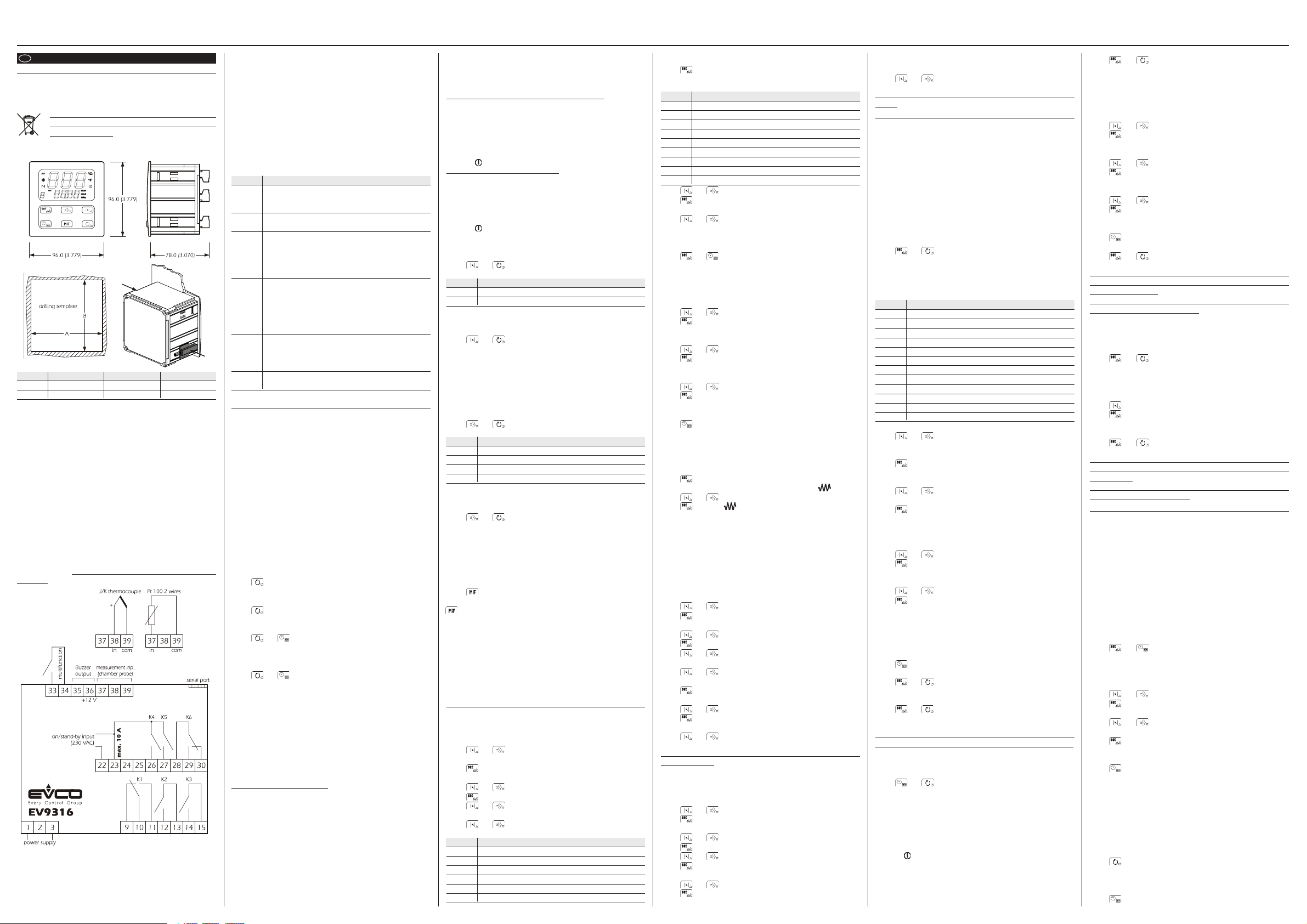
1.2 Dimensions and installation
Panel with supplied brackets with screws; dimensions in mm (in).
DIMENS. MINIMUM TIPYCAL MAXIMUM
A 92.0 (3.622) 92.0 (3.622) 92.8 (3.653)
B 92.0 (3.622) 92.0 (3.622) 92.8 (3.653)
Installation recommendations:
• the thickness of the panel must not exceed 4.0 mm (0.157 in)
• position the brackets as indicated in the drawing in this paragraph,
moderate the coupling torque
• make sure that the working conditions (temperature of use, humidity,
etc.) lie within the limits indicated in the technical data
• do not install the instrument in proximity of heat sources (resistances,
hot air pipes, etc.), appliances with strong magnets (large diffusers,
etc.), places subject to direct sunlight, rain, humidity, excessive dust,
mechanical vibrations or jerks
• in compliance with Safety Standards, protection against any contact
with electrical parts must be assured via correct installation of the
instrument. All parts that ensure protection must be fixed in a way that
they cannot be removed without the aid of a tool.
1.3 Electric connection
With reference to the wiring diagram: the serial port is the port for the
communication with the supervising system (through a serial inter-
face, via TTL, with MODBUS communication protocol) or with the
programming key; the port must not be used for two purposes at the
same time.
Recommendations for the electric connection:
• do not operate on the terminal boards using electric or pneumatic
• if the instrument has been taken from a cold place to a hot place, the
humidity could condense inside; wait for about one hour before
applying power
• check that the power supply voltage, the frequency and the electric
operational power of the instrument correspond with those of the
local power supply
• disconnect the power supply before performing any type of mainte-
nance
• supply the probe with protection able to isolate it from any contact
with metal parts or use isolated probes
• do not use the instrument as a safety device
• for repairs and information regarding the instrument, contact the
Evco sales network.
1.4 Functions associated with the digital outputs
It is possible to set the utility managed by each digital output (i.e. relays
K1 ... K6).
OUTPUT PREDEFINED FUNCTION
K1 Temperature regulation
The output activity mainly depends on the work set-point
and the parameter r0
K2 Cooking timer
The output is activated during the cooking timer count
K3 Acoustics
The output is activated in the following conditions:
• 10 s before the conclusion of the cooking timer count, for
the time established with parameter c4
• during alarms and errors, with continuous contribution
K4 Airhole
The output is activated in the following conditions:
• before the conclusion of the cooking timer count (of the
time established with the parameter c5), for the time estab-
lished with parameter c6
• in manual mode, for the time established for parameter c7
K5 Steam injection
The output activity depends mainly on parameter t0
Through the multifunction input it is also possible to acti-
vate the output in remote mode
K6 On/stand-by input
The output is activated during the on state
To set the utility managed by each output, see paragraph 3.1.
2 USER INTERFACE
2.1 Preliminary considerations
The following functioning states exist:
• the “on” state (the instrument is powered and on: the regulators can be on)
• the “programmed switch-on” state (the instrument is powered but
switched off via software: the regulators are off and programmed
switch-on of the instrument is envisioned)
• the “stand-by” state (the instrument is powered but switched off via
software: the regulators are off and programmed switch-on of the
instrument is not envisioned)
• the “off” state (the instrument is not powered).
Successively, the term "switch-on" means the passage from the stand-by
state to the on state. The term "switch-off" means the passage from the
on state to the stand-by state.
When powered, the instrument re-proposes the state that it was in when
the power supply was disconnected.
2.2 Selecting the functioning state
To pass from the stand-by state to the on state (and vice versa):
• make sure no procedure is in progress
• press for 1s.
To pass from the programmed switch-on state to the on state:
• make sure no procedure is in progress
• press for 1s.
To pass from the on state to the programmed switch-on state:
• make sure no procedure is in progress
• press and for 1s.
To pass from the stand-by state to the programmed switch-on state (and
vice versa):
• make sure no procedure is in progress
• press and for 1s.
Through the on/stand-by input it is also possible to pass from the on
state to the stand-by state in remote mode.
To pass from the on to the stand-by state in remote mode:
• activate the on/stand-by input (the instrument remains in the stand-by
state for the entire duration of input activation).
The activation of the on/stand-by input causes the passage from the on
state or from the programmed switch-on state to the stand-by state: the
successive deactivation always causes the passage to the on state. If the on/
stand/by input is active, it will not be allowed to pass from the stand-by state
to the on state (or programmed switch-on state) by pressing the keys.
2.3 The display
If the instrument is in the on state:
• the upper part of the display will show the quantity established with
parameter P5:
- if P5 = 0, the display will show the chamber temperature
- if P5 = 1, the display will show the work set-point
• the lower part of the display will show the quantity established with
parameter P6:
- if P6 = 0, the display will show the chamber temperature
- if P6 = 1, the display will show the work set-point (in this case the “set”
LED will be on)
- if P6 = 2, the display will show the value of the cooking timer or its
count if the timer is active (in this case the “timer” LED will be on); the
value of the cooking timer is displayed in the hours:minutes format.
- if P6 = 3, the display will show the day and real time (in this case the
“clock” LED will be on); the day is displayed in format 1 ... 7 (number 1
corresponds to Monday), the real time in the 24 h format.
See also paragraphs 3.5 and 3.6.
If the instrument is in the programmed switch-on state:
• the upper part of the display will be off:
• the lower part of the display will show the day and time of the next
switch-on; the day is displayed in format 1 ... 7 (number 1 corre-
sponds to Monday), the real time in 24 h format (if switch-on is not
programmed, the lower part of the display will show “- - - -”)
• the “delay” LED will be on
• the LED will be on.
If the instrument is in the stand-by state:
• the upper part of the display will be off:
• the lower part of the display:
- will be off if parameter c8 is set at 0
- it will display the real time if parameter c8 is set at 1 (in this case the
“clock” LED will be on); the real time is displayed in 24 h format
• the LED will be on.
2.4 Learning the quantity shown by the upper part of
the display during the on state
• make sure no procedure is in progress
• press and : the upper part of the display will show one of the
labels given in the following table for 2 secs:
LABEL MEANING
Pb chamber temperature
SP work set-point
2.5 Temporary setting of the quantity shown by the
upper part of the display during the on state
• make sure no procedure is in progress
• press and for 1s several times: the upper part of the display
will show one of the labels given in the table in
paragraph 2.4 for 2 secs, after which it will show
the corresponding value.
Any power supply cut-off causes the display of the quantity established
with parameter P5 to be restored.
2.6 Learning the quantity shown by the lower part of
the display during the on state
• make sure no procedure is in progress
• press and : the lower part of the display will show one of the
labels given in the following table for 2 secs:
LABEL MEANING
Pb chamber temperature
SP work set-point
tine value of the cooking timer or its count if the timer is active
rtc day and real time
2.7 Temporary setting of the quantity shown by the
lower part of the display during the on state
• make sure no procedure is in progress
• press and for 1s several times: the lower part of the display
will show one of the labels given in the table in
paragraph 2.6 for 2 secs, after which it will show
the corresponding value.
Any power supply cut-off causes the display of the quantity established
with parameter P6 to be restored.
2.8 Chamber light switch-on/off
• make sure no procedure is in progress
• press
If the chamber light is not managed by any digital output , pressing the
key will cause the display of the flashing “no” indication for 2 s in
the lower part of the display.
2.9 Buzzer silencing
• make sure no procedure is in progress
• press a key (the first time the key is pressed, the associated effect is not
caused).
Pressing the key also causes the deactivation of the acoustic output and
the buzzer output.
Using the multifunction input, it is also possible to deactivate the buzzer,
the acoustic output and the buzzer output in remote mode.
3 SETTINGS
3.1 Setting the utility managed by each digital output
To access the procedure:
• make sure that the instrument is in stand-by state and that no proce-
dure is in progress
• press and for 4s: the upper part of the display will show
“PA”
• press : the lower part of the display will show the corresponding
value
• press or within 15s to set “743”
• press
• press and for 4s: the upper part of the display will show
“dEF”
• press or to select “do1 ... do6”.
The label meaning is the following:
LABEL MEANING
do1 utility managed by the first digital output (relay K1)
do2 utility managed by the second digital output (relay K2)
do3 utility managed by the third digital output (relay K3)
do4 utility managed by the fourth digital output (relay K4)
do5 utility managed by the fifth digital output (relay K5)
do6 utility managed by the sixth digital output (relay K6)
To modify the utility managed by an output:
• press : the lower part of the display will show the corresponding
value.
The meaning of the values is the following:
VALUE MEANING
0 not used
1 temperature regulation
2 cooking timer
3 acoustics
4 airhole
5 steam injection
6 on/stand-by
7 alarm
8 chamber light
• press or within 15s
• press
To exit the procedure:
• press and for 4s.
3.2 Setting the day and the real time
• make sure that the instrument is in stand-by state and that no proce-
dure is in progress
• press and : the lower part of the display will show the day of
the week and the real time; the indication relative
to the day and the “clock” LED will flash.
The day is displayed in format 1 ... 7 (number 1 corresponds to Mon-
day), the real time in the 24 h format (hours:minutes).
To modify the day:
• press or within 15s
• press : the left part of the indication relative to the real time will
flash.
To modify the hour:
• press or within 15s
• press : the right part of the indication relative to the real time will
flash.
To modify the minutes:
• press or within 15s
• press : the “clock” LED will switch-off, after which the instrument
will exit the procedure.
To go back to previous levels:
• press several times during the procedure.
To exit the procedure in advance:
• do not operate for 15s (any modifications will be saved).
3.3 Setting the work set-point
• make sure that the instrument is in on state and that no procedure is
in progress
• press : the lower part of the display will show “SP”, the upper
part the corresponding value and the LED will flash
• press or within 15s; see also parameters r1 and r2
• press : the LED will switch-off, after which the instrument
will exit the procedure.
To exit the procedure in advance:
• do not operate for 15s (any modifications will be saved).
It is also possible to set the work set-point via the SP parameter.
3.4 Setting the configuration parameters
To access the procedure:
• make sure that the instrument is in stand-by state and that no procedure is in progress
• make within 15s to set is in stand-by state and that no procedure is in
progress
• press and for 4s: the upper part of the display will show “PA ”
• press : the lower part of the display will show the corresponding
value
• press or within 15s to set “-19”
• press or do not operate for 15s
• press and for 4s: the upper part of the display will show “SP”.
To select a parameter:
• press or
To modify a parameter:
• press : the lower part of the display will show the corresponding
value
• press or within 15s
• press or do not operate for 15s.
To exit the procedure:
• press and for 4s or do not operate for 60 s (any modifica-
tions will be saved).
Cut the instrument power supply off after modification of
the parameters.
3.5 Restore the default value of the configuration pa-
rameters
• make sure that the instrument is in stand-by state and that no proce-
dure is in progress
• press and for 4s: the upper part of the display will show “PA”
• press : the lower part of the display will show the corresponding
value
• press or within 15s to set “743”
• press or do not operate for 15s
• press and for 4s: the upper part of the display will show “dEF”
• press : the lower part of the display will show the corresponding
value
• press or within 15s to set “149”
• press or do not operate for 15s: the upper part of the display will
show “dEF” flashing for 4s, after which “dEF” will switch on
• cut the instrument power supply off.
To exit the procedure in advance:
• press and for 4s during the procedure (i.e. before setting
“149”: restore will not be carried out).
Make sure that the default value of the parameters is appro-
priate.
4 PROGRAMMED IGNITION
4.1 Preliminary considerations
Programmed ignition allows to plan the automatic switch-on of the
instrument.
On switch-on the instrument will function with the latest settings memo-
rised before being passed to the programmed switch-on state (see
paragraph 2.2).
It is possible to plan 14 switch-on hours, the possible combinations of
switch-on days are 12.
If there is a power cut at the switch-on time, this will be re-proposed
when the power supply is restored.
5.2 Setting programmed ignition
To access the procedure:
• make sure that the instrument is in on state and that no procedure is
in progress
• press and : the upper part of the display will show “H01”
flashing (it is the label of the first switch-on time),
the lower part will show a label relative to a combination of switch-on days and the “delay” LED
will flash.
The combination of the switch-on days available are the following:
LABEL COMBINATION OF DAYS
- - - Never
- 1 - Monday
- 2 - Tuesday
- 3 - Wednesday
- 4 - Thursday
- 5 - Friday
- 6 - Saturday
- 7 - Sunday
1 - 5 from Monday to Friday
1 - 6 from Monday to Saturday
1 - 7 from Monday to Sunday
6 - 7 Saturday and Sunday
To select a switch-on time:
• press or within 15s (e.g. to select “H07”).
To select a combination of days to which to apply the selected switchon time (in the example, “H07”):
• press during flashing of the upper part of the display: the lower
part of the display will show a flashing label relative to a
combination of days and the upper part will switch-on
• press or within 15s (for example to select “1 - 5”).
To set the selected switch-on time (in the example, “H07”):
• press during flashing of the lower part of the display: the lower
part of the display will show the switch-on time; the left part
will flash.
The time is displayed in the 24h format (hours:minutes).
To modify the hour:
• press or within 15s
• press : the right part of the indication relative to the switch-on
time will flash.
To modify the minutes:
• press or within 15s
• press : the upper part of the display will show the flashing switch-
on time label again (in the example “H07”) and the lower
part will show the combination of days again (in the example “1 - 5”).
To set another programmed ignition, repeat the procedure given in
this paragraph.
To go back to previous levels:
• press several times during the procedure.
To exit the procedure:
• press and or do not operate for 15s: the “delay” LED switches
off.
To exit the procedure in advance:
• press and or do not operate for 15s during the procedure
(i.e. before modifying the minutes: any modifica-
tions will not be saved).
For the instrument to automatically switch-on at the day and
time set, these must be in the programmed switch-on mode.
To pass from the on state (or the stand-by state) to the programmed
switch-on state:
• make sure no procedure is in progress
• press and for 1s.
If the instrument is in the programmed switch-on state:
• the upper part of the display will be off:
• the lower part of the display will show the day and time of the next
switch-on; the day is displayed in format 1 ... 7 (number 1 corre-
sponds to Monday), the real time in 24 h format (if switch-on is not
programmed, the lower part of the display will show “- - - -”)
• the “delay” LED will be on
• the LED will be on.
5.3 Temporary modification of the day and time of the
next switch-on
To access the procedure:
• make sure that the instrument is in the programmed switch-on state
and that no procedure is in progress
• press and : the lower part of the display will show the day of
the week and the time of the next switch-on, the
indication relative to the day and the “delay” LED
will flash.
The day is displayed in format 1 ... 7 (number 1 corresponds to Mon-
day), the time in the 24 h format (hours:minutes).
To modify the day:
• press or within 15s
• press : the left part of the indication relative to the switch-on time
will flash.
To modify the hour:
• press or within 15s
• press : the right part of the indication relative to the switch-on
time will flash.
To modify the minutes:
• press or within 15s
• press : the “delay” LED will switch-on, after which the instru-
ment will exit the procedure.
To go back to previous levels:
• press several times during the procedure.
To exit the procedure in advance:
• press and or do not operate for 15s (any modifications ill
not be saved).
The temporary modification of an ignition is re-proposed also after a
power cut and has exclusive effect on the imminent switch-on and not
on those previously set.
If passing from the programmed switch-on state to any other state, the
modification will not be re-proposed.
5.4 Exclusion of the next switch-on for the benefit of
another already programmed
• make sure that the instrument is in the programmed switch-on state
and that no procedure is in progress
• press and for 1s: the lower part of the display will show the
day of the week and the time of the next switch-
on, the “delay” LED will flash.
The day is displayed in format 1 ... 7 (number 1 corresponds to Mon-
day), the time in the 24 h format.
• press within 15s to select another switch-on already programmed
• press : the “delay” LED will switch-on, after which the instru-
ment will exit the procedure.
To exit the procedure in advance:
• press and or do not operate for 15s (any modifications will
not be saved).
The exclusion of a switch-on is re-proposed also after a power-cut. The
switch-ons excluded are re-proposed in the successive day and time
circumstances.
If passing from the programmed switch-on state to any other state, the
exclusion will not be re-proposed.
5 COOKING TIMER
5.1 Preliminary considerations
The cooking timer allows to start the reverse countdown of a time.
The countdown is shown in the lower part of the display; during the
count the “timer” LED is on and the timer output is activated.
Before conclusion of the count (of the time established with parameter c9)
the buzzer and the acoustic output are activated, for the time estab-
lished with parameter c4.
Before conclusion of the count (of the time established with parameter c5)
the airhole is activated, for the time established with parameter c6.
Using the multifunction input, it is also possible to start/interrupt the
cooking timer in remote mode.
5.2 Setting the cooking timer
• make sure that the instrument is in the on state, that the cooking timer
count is not in progress and that no procedure is in progress
• press and : the lower part of the display shows the value of
the cooking timer; the left part and the “timer”
LED will flash.
The value of the cooking timer is displayed in the hours:minutes format.
To modify the hour:
• press or within 15s
• press : the right part will flash.
To modify the minutes:
• press or within 15s.
The cooking timer can be set between 00:00 and 24:00 h:min.
• press : the “timer” LED will switch-off, after which the instrument
will exit the procedure.
To go back to previous levels:
• press several times during the procedure.
To exit the procedure in advance:
• do not operate for 15s (any modifications will be saved).
The cooking timer can also be set when the count is in progress (this
modification is temporary, i.e. any power supply cut-off causes the
value set with the procedure given at the start of this paragraph to be
restored). If the value is set at 00:00 h:min, the count will be inter-
rupted, the “timer” LED will switch-off and the buzzer will be acti-
vated for 3 seconds.
5.3 Starting the cooking timer
• press during timer setting: the “timer” LED will switch on.
Alternatively:
• make sure that the instrument is in on state and that no procedure is
in progress
• press : the “timer” LED will switch on.
Page 2
5.4 Interrupting the cooking timer
• press for 1s: the “timer” LED switches off and the buzzer will be
activated for 3s.
6 STEAM INJECTION
6.1 Preliminary considerations
The functioning mode of the steam injection depends on parameter t0.
If the parameter t0 is set at 0, pressing the key causes the injection
of steam for the time established with parameter t2 or for the entire
duration that the key is pressed. The parameter t1 establishes the mini-
mum time that can pass between the two successive injections.
If the parameter t0 is set at 1, pressing the key will enable the
automatic injection of the steam (in cyclical mode: parameter t2 estab-
lishes the duration of the injector switch-on and parameter t1 estab-
lishes the duration of switch-off).
Using the multifunction input, it is also possible to cause the same effect
by pressing the key in remote mode.
If the steam injection is not managed by any digital output , pressing the
key will cause the display of the “no” indication for 1s in the lower
part of the display.
6.2 Quick setting of the parameter t2
• make sure that the instrument is in on state and that no procedure is
in progress
• press and : the upper part of the display will show “t2”, the
lower part the corresponding value and the LED
will flash.
The parameter t2 can be set between 1 and 250 ds.
If steam injection is not managed by any digital output, the lower part
of the display will show “no” for 1s.
• press or within 15s
• press : the LED will switch-off, after which the instrument will
exit the procedure.
To exit the procedure in advance:
• do not operate for 15s (any modifications will be saved).
7 AIRHOLE
7.1 Preliminary considerations
The airhole is activated in the following conditions:
• before the conclusion of the cooking timer count (of the time established
with the parameter c5), for the time established with parameter c6
• in manual mode, by pressing the , key for the time established
with parameter c7.
If the airhole is not managed by any digital output, pressing the
key will cause the display of the “no” indication for 1s in the lower part
of the display.
7.2 Quick setting of the parameter c7
• make sure that the instrument is in on state and that no procedure is
in progress
• press and : the upper part of the display will show “c7”, the
lower part the corresponding value, the left part
and the LED will flash.
The parameter c7 is visualised in the minutes:seconds format.
To modify the minutes:
• press or within 15s
• press : the right part will flash.
To modify the seconds:
• press or within 15s.
The parameter c7 can be set between 00:00 and 60:00 min:s.
If the airhole is not managed by any digital output, the lower part of the
display will show “no” for 1s.
• press : the LED will switch-off, after which the instrument will
exit the procedure.
To go back to previous levels:
• press several times during the procedure.
To exit the procedure in advance:
• do not operate for 15s (any modifications will be saved).
7.3 Activation of the airhole in manual mode
• make sure that the instrument is in on state and that no procedure is
in progress
• press : the LED will switch on and the airhole will be activated,
both for the time established with parameter c7.
7.4 Airhole deactivation
• make sure no procedure is in progress
• press : the LED will switch-off.
8 SIGNALS
8.1 Signals
LED MEANING
temperature regulation LED
if it is on, the output for the regulation of the temperature
will be activated
if it flashes, the work set-point modification is in progress
(with the procedure indicated in paragraph 3.3)
steam injection LED
if it is on:
• and the parameter t0 is set at 0, steam injection will be in
progress
• and the parameter t0 is set at 1, steam injection will be in
enabled
if it flashes, rapid setting of parameter t2 is in progress (see
paragraph 6.2)
airhole LED
if it is on, the airhole will be activated in manual mode
if it flashes:
• the airhole will be activated due to the effect of the conclu-
sion of the cooking timer count (parameter c6)
• rapid setting of parameter c7 is in progress (see para-
graph 7.2)
°C degrees Celsius LED
if it is on, the unit of measurement of the temperatures will
be degrees Celsius (parameter P2)
°F degrees Fahrenheit LED
if it is on, the unit of measurement of the temperatures will
be degrees Fahrenheit (parameter P2)
on/stand-by LED
if it is on, the instrument is in the programmed switch-on
state or in the stand-by state
delay programmed switch-on LED
if it is on, the instrument is in the programmed switch-on
state
if it is flashing, setting of the programmed switch-on day
and time is in progress
clock real time LED
if it is on, the quantity displayed by the lower part of the
display will be the real time
if it is flashing, setting of the day and real time is in progress
timer cooking timer LED
if it is on, the quantity shown by the lower part of the display
will be the value of the cooking timer or its count if the timer
will be activated
if it flashes:
• cooking timer setting is in progress
• the cooking timer count will be in progress but the lower
part of the display will be showing another quantity
set work set-point LED
if it is on, the quantity shown by the lower part of the display
will be the work set-point value
9 INDICATIONS
9.1 Indications (in the lower part of the display)
INDICAT. MEANING
decrease the time established with parameter c9 is missing... 1 second
time to the conclusion of the cooking timer count
c9
00:00 flashing: the cooking timer count has ended
10 ALARMS
10.1 Alarms
CODE MEANING
AL temperature alarm
Remedies:
• check the chamber temperature
• see parameters A1 and A3
Consequences:
• the alarm output will be activated
• the acoustics output and the buzzer output will be acti-
vated
PF1 power supply cut-off alarm during cooking timer count
with duration shorter than the time established with param-
eter r13
Remedies:
• press a key to restore the normal display
• check the causes that brought about the power supply
cut-off
Main consequences:
• the count will continue until the instrument is powered
• the acoustics output and the buzzer output will be acti-
vated
PF2 power supply cut-off alarm during cooking timer count
with duration longer than the time established with param-
eter r13
Remedies:
• press a key to restore the normal display
• check the causes that brought about the power supply
cut-off
Main consequences:
• the count will be interrupted
• the acoustics output and the buzzer output will be activated
When the cause of the alarm disappears, the instrument restores nor-
mal functioning, except for the power supply cut-off alarm during the
cooking timer count (codes “PF1” and “PF2”) which requires a key to
be pressed.
11 INTERNAL DIAGNOSTICS
11.1 Internal diagnostics
CODE MEANING
Pr1 chamber probe error
Remedies:
• in the models for J/K thermocouple, see parameter P0, in
the models for Pt 100 probe, check the type of probe
• check probe integrity
• check the instrument-probe connection
• check the chamber temperature
Main consequences:
• the temperature regulation output will be deactivated
• the acoustics output and the buzzer output will be acti-
vated
rtc the lower part of the display: clock error
Remedies:
• set the day and real time again
Main consequences:
• the programmed switch-on will not be available
• the acoustics output and the buzzer output will be activated
When the cause of the alarm disappears the instrument restores normal
functioning, except for clock error (code “rtc”) that requires the day
and real time to be set.
12 TECHNICAL DATA
12.1 Technical data
Container: grey self-extinguishing.
Front panel protection rating: IP 54.
Connections: removable terminal boards (power supply, inputs and
outputs), 6-pole connector (serial port).
Temperature of use: from 0 to 55 °C (from 32 to 131 °F, 10 ... 90%
relative humidity without condensate).
Power supply: 115 ... 230 VAC, 50/60 Hz, 5 VA (approx) or 24 VAC,
50/60 Hz.
Keeping the clock data in a power-cut: 24 h with battery
charged.
Battery charging time: 2 min without interruptions (the battery is
charged by the instrument power supply).
Alarm buzzer: incorporated.
measurement inputs: 1 (chamber probe) for J/K thermocouple or
Pt 100 2 wire probe (according to the model).
Digital inputs: 2 inputs:
• on/stand-by input in high voltage (230 VAC) with
configurable polarity
• multifunction input, for NO/NC contact (potential-
free contact, 5 V 1 mA).
Range of measurement: from -99 to 800 °C (from -99 to 999 °F) for
J thermocouple, from -99 to 999 °C (from -99 to 999 °F) for K thermocouple, from -99 to 650 °C (from -99 to 999 °F) for Pt 100 probe.
13 WORK SET-POINT AND CONFIGURATION PARAMETERS
13.1 Work set-point
MIN. MAX. U.M. DEF.
r1 r2 °C/°F (1) 1 50
WORK SET-POINT
work set-point
13.2 Configuration parameters
PARAM. MIN. MAX. U.M. DEF.
SP r1 r2 °C/°F (1) 1 50
PARAM. MIN. MAX. U.M. DEF.
CA1 -25/-5025/50 °C/°F (1) 0
P0 0 1 - - - - 0
WORK SET-POINT
work set-point
MEASUREMENT INPUTS
chamber probe offset
type of probe (not visible in the models for Pt 100 probe)
0=J
1=K
P2 0 1 - - - - 0
temperature unit of measurement (2)
0=°C
1=°F
P5 0 1 - - - - 0
quantity shown by the upper part of the display during the on state or during normal functioning
0 = chamber temperature
1 = work set-point
P6 0 3 - - - - 2
quantity shown by the lower part of the display during the on state or during normal functioning
0 = chamber temperature
1 = work set-point
2 = value of the cooking timer or its count if the timer is active
3 = day and real time
PARAM. MIN. MAX. U.M. DEF.
r0 1 99 °C/°F (1) 5
r1 0 r2 °C/°F (1) 5 0
r2 r1 999 °C/°F (1) 3 50
r1 2 0 1 - - - - 0
MAIN REGULATOR
work set-point differential
minimum work set-point
maximum work set-point
restraint between the output state for the regulation of the temperature and the cooking timer
1=YES - the temperature regulation output remains off if the cooking timer count is not in progress
r13 0 240 min 240
duration of a power supply cut-off duration that occurs during a cooking timer count exceeding
which the count is interrupted (3)
PARAM. MIN. MAX. U.M. DEF.
t0 0 1 - - - - 0
STEAM INJECTION
steam injection functioning mode
0 = pressing the key causes the injection of steam for the time established with parameter t2 or for
the entire duration that the key is pressed. The parameter t1 establishes the minimum time that can
pass between the two successive injections
1 = pressing the key enables automatic injection of the steam in cyclical mode (parameter t2
establishes the switch-on duration of the injector and parameter t1 establishes switch-off duration)
t1 0 250 s 1
if t0 = 0, minimum time that passes between two successive injections
if t0 = 1, injector switch-off duration
t2 1 25 0 ds (4) 10
if t0 = 0, minimum injection duration
if t0 = 1, injector switch-on duration
PARAM. MIN. MAX. U.M. DEF.
c4 -1 120 s 15
VARIOUS
duration of buzzer activation and of the acoustic output on conclusion of the cooking timer count; see
also c9 (5) (6)
-1 = the buzzer and the acoustic output must be deactivated in manual mode by pressing a key
c5 0 60 min 20
time that passes between the activation of the airhole and the conclusion of the cooking timer count,
see also c6
c6 0 60 min 20
c7 00:00 60:00 min:s 00:30
c8 0 1 - - - - 1
duration of the activation of the airhole at conclusion of the cooking timer count, see also c5
duration of the activation of the airhole in manual mode
showing the real time in the lower part of the display during the stand-by state
1 = YES
c9 0 120 s 10
time that passes between the activation of the buzzer and the acoustic output and the conclusion of the
cooking timer count, see also c4
c12 0 99 9 min 60
time that must pass (from programmed switch-on of the instrument) without having operated on the
keys so that the instrument passes to the programmed switch-on state again
0 = no function
PARAM. MIN. MAX. U.M. DEF.
A1 0 999 °C/°F (1) 0
A2 0 240 min 0
A3 0 2 - - - - 0
TEMPERATURE ALARMS
temperature above which the temperature alarm is activated, se also A3 (7)
temperature alarm delay
type of temperature alarm
0 = no alarm
1 = absolute (i.e. A1)
2 = relative to the work set-point (i.e. “work set-point + A1”)
EVCO S.p.A. This document belongs to Evco; unless you are authorized by Evco, you can not publish it.
Via Mezzaterra 6, 32036 Sedico Belluno ITALY Evco does not take any responsibility about features, technical data and possible mistakes related in this document or coming by its use.
Phone +39-0437-852468 • Fax +39-0437-83648 Evco does not take any responsibility about damages coming by the non-observance of the additional information.
PT • 35/09
[email protected] • www.evco.it Evco reserves the right to make any change without prior notice and at any time without prejudice the basic safety and operating features.
Resolution: 1 °C/1 °F.
Digital outputs: 6 relays:
• temperature regulation relay: 8 A res. @ 250
VCA (contact in exchange)
• cooking timer relay: 8 A res. @ 250 VCA (NO
contact)
• acoustic output relay: 8 A res. @ 250 VCA (NO
contact)
• airhole relay: 8 A res. @ 250 VCA (NO contact)
• steam injection relay: 8 A res. @ 250 VCA
(NO contact)
• on/stand-by relay: 8 A res. @ 250 VCA (contact
in exchange).
The maximum current accepted on clamp 23 is 10 A.
To set the utility managed by each output, see paragraph 3.1.
Other outputs: buzzer output (12 V, max. 20 mA); the output is
activated during alarms and errors, with continuous contribution.
Serial port: port for the communication with the supervising system
(through a serial interface, via TTL, with MODBUS communication
protocol) or with the programming key.
PARAM. MIN. MAX. U.M. DEF.
i1 0 1 - - - - 0
DIGITAL INPUTS
polarity of the on/stand-by input (instrument off with input active) (8)
0 = live input active
1 = non-live input active
i5 0 3 - - - - 0
effect caused by the activation of the multifunction input
0 = no effect
1=STAR/INTERRUPTION OF THE COOKING TIMER - the activation of the input will cause the cooking
timer to start and the successive activation will cause its interruption
2=BUZZER, ACOUSTIC OUTPUT AND BUZZER OUTPUT DEACTIVATION - the activation of the input will
cause deactivation of the buzzer, the acoustic output and the buzzer output (activate the input again
to deactivate these utilities again)
3=STEAM INJECTION - in this case:
• if t0 = 0, the activation of the input causes the injection of steam for the time established with
parameter t2 or for the entire duration that the key is pressed (parameter t1 establishes the minimum
time that can pass between the two successive injections) (9)
• if t0 = 1, the activation of the input will enable automatic steam injection (in cyclical mode; param-
eter t2 establishes the duration of the switch-on of the injector and parameter t1 establishes the
duration of switch-off) until the input is activated again (9)
i6 0 1 - - - - 0
type of contact of the multifunction input
0 = NO (input active with closed contact)
1 = NC (input active with open contact)
PARAM. MIN. MAX. U.M. DEF.
LA 1 2 47 - - - - 24 7
Lb 0 3 - - - - 2
SERIAL NETWORK (MODBUS)
instrument address
baud rate
0 = 2.400 baud
1 = 4.800 baud
2 = 9.600 baud
3 = 19.200 baud
LP 0 2 - - - - 2
parity
0 = none (no parity)
1 = odd
2 = even
(1) the unit of measurement depends on parameter P2
(2) set the parameters relative to the regulators appropriately after modification of parameter P2
(3) if the power supply cut-off is shorter than the time established with parameter r13, the count will also continue when the instrument is not
powered
(4) ds = tenths of second
(5) the buzzer and the acoustic output are activated 10 s before the conclusion of the count of the cooking timer, for the time established with
parameter c4
(6) if the cooking timer is interrupted (with the procedure given in paragraph 5.4 or by activation of the malfunction input), the duration of
buzzer activation and of the acoustic output and the flashing duration of the 00:00 indication will be 3 seconds
(7) the parameter differential is 10 °C/18 °F
(8) the activation of the on/stand-by input causes the passage from the on state or from the programmed switch-on state to the stand-by state:
the successive deactivation always causes the passage to the on state. If the on/stand-by input is active, it will not be allowed to pass from
the stand-by state to the on state or the programmed switch-on state by pressing the keys
(9) pressing the key causes the associated effect.
 Loading...