

Page 1
EVCO S.p.A. EV3 HP & EVD HP | Installer manual ver. 1.2 | Code 1443DHPE124
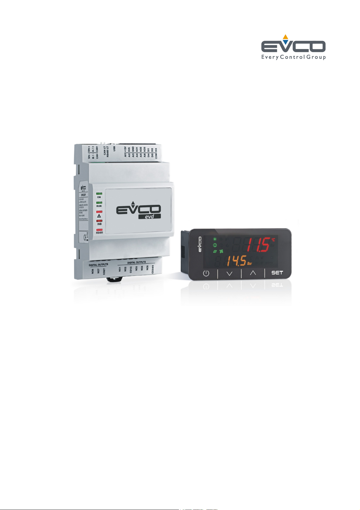
EV3 HP & EVD HP
Controllers for reversible single-circuit
residential heat pumps
Installer Manual | ENGLISH
Code 1443DHPI124
page 1 of 52
Page 2

EVCO S.p.A. EV3 HP & EVD HP | Installer manual ver. 1.2 | Code 1443DHPE124
Important
Read this manual carefully before installation and before using the devices and take all the prescribed precautions. Keep this manual
with the devices for future consultation.
Only use the devices in the ways described in this manual. Do not use these devices as safety devices.
Disposal
The devices must be disposed of according to local regulations governing the collection of electrical and electronic waste.
page 2 of 52
Page 3

EVCO S.p.A. EV3 HP & EVD HP | Installer manual ver. 1.2 | Code 1443DHPE124
Index
1 INTRODUCTION ......................................................................................................................................................... 5
1.1 Introduction .............................................................................................................................................................. 5
1.2 Models available, purchasing codes and technical features .............................................................................................. 6
2 DESCRIPTION ............................................................................................................................................................ 8
2.1 Description of EV3 HP ................................................................................................................................................. 8
2.2 Description of EVD HP................................................................................................................................................. 9
2.3 Description of EV3K01 .............................................................................................................................................. 10
3 MEASUREMENTS AND INSTALLATION ......................................................................................................................... 11
3.1 Measurements and installation of EV3 HP .................................................................................................................... 11
3.2 Measurements and installation of EVD HP ................................................................................................................... 11
3.3 Measurements and installation of EV3K01 ................................................................................................................... 13
3.4 Installation precautions............................................................................................................................................. 13
4 ELECTRICAL CONNECTION ........................................................................................................................................ 14
4.1 I/O configuration ..................................................................................................................................................... 14
4.2 Description of connectors .......................................................................................................................................... 15
4.2.1 Description of connectors for EV3 HP .......................................................................................................................... 15
4.2.2 Description of connectors for EVD HP.......................................................................................................................... 17
4.2.3 Description of EV3K01 connectors .............................................................................................................................. 19
4.3 Termination of the RS-485 MODBUS line ..................................................................................................................... 20
4.4 Example of electrical connection ................................................................................................................................ 21
4.4.1 Example of EV3 HP electrical connection ..................................................................................................................... 21
4.4.2 Example of EVD HP electrical connection ..................................................................................................................... 22
4.5 Precautions for electrical connection ........................................................................................................................... 23
5 DESCRIPTION OF USER INTERFACE ........................................................................................................................... 24
5.1 Key functions .......................................................................................................................................................... 24
5.2 Display ................................................................................................................................................................... 24
5.3 Signals ................................................................................................................................................................... 25
5.4 Menu ...................................................................................................................................................................... 27
5.4.1 Access levels ........................................................................................................................................................... 27
5.4.2 Menu list ................................................................................................................................................................. 27
6 LIST OF PARAMETERS .............................................................................................................................................. 28
6.1 Initial information .................................................................................................................................................... 28
7 REGULATORS .......................................................................................................................................................... 33
7.1 Initial information .................................................................................................................................................... 33
7.2 Function mode ......................................................................................................................................................... 33
7.3 Compressor ............................................................................................................................................................. 33
7.3.1 Adjustment in cold mode .......................................................................................................................................... 34
7.3.2 Adjustment in hot mode ........................................................................................................................................... 35
7.3.3 Oil refresh ............................................................................................................................................................... 35
7.4 Hydraulic pump ....................................................................................................................................................... 36
7.4.1 Initial information .................................................................................................................................................... 36
7.4.2 Function modes ....................................................................................................................................................... 36
7.4.3 Antifreeze function ................................................................................................................................................... 36
7.5 Electric heating elements .......................................................................................................................................... 37
7.5.1 Initial information .................................................................................................................................................... 37
7.5.2 Heating elements in integration mode ........................................................................................................................ 37
7.5.3 Heating elements in antifreeze mode .......................................................................................................................... 37
7.6 Condensation control ................................................................................................................................................ 38
7.6.1 Initial information .................................................................................................................................................... 38
7.6.2 Adjustment in cold mode .......................................................................................................................................... 38
7.6.3 Adjustment in hot mode ........................................................................................................................................... 39
7.6.4 Regolazione in sbrinamento ....................................................................................................................................... 39
7.7 Defrost ................................................................................................................................................................... 40
7.7.1 Initial information .................................................................................................................................................... 40
page 3 of 52
Page 4

EVCO S.p.A. EV3 HP & EVD HP | Installer manual ver. 1.2 | Code 1443DHPE124
7.7.2 Start defrost control ................................................................................................................................................. 40
7.7.3 End defrost control ................................................................................................................................................... 40
8 ALARMS .................................................................................................................................................................. 41
8.1 Initial information .................................................................................................................................................... 41
8.2 List of alarms .......................................................................................................................................................... 41
9 ACCESSORIES ......................................................................................................................................................... 43
9.1 EVIF20SUXI RS-485/USB serial interface .................................................................................................................... 43
9.1.1 Initial information .................................................................................................................................................... 43
9.2 0025100010 drip protector........................................................................................................................................ 43
9.2.1 Initial information .................................................................................................................................................... 43
9.3 CJAV connection kit .................................................................................................................................................. 43
9.3.1 Initial information .................................................................................................................................................... 43
10 TECHNICAL SPECIFICATIONS .................................................................................................................................... 44
10.1 Technical specifications ............................................................................................................................................. 44
page 4 of 52
Page 5

EVCO S.p.A. EV3 HP & EVD HP | Installer manual ver. 1.2 | Code 1443DHPE124
1 INTRODUCTION
1.1 Introduction
EV3 HP and EVD HP are controllers for reversible air-water and
water-water single-circuit residential heat pumps.
EV3 HP is available in the standard 74x32mm format with
built-in user interface consisting of a double custom display,
with decimal point and function icons, and four touch keys. It
guarantees IP65 protection for easy cleaning.
EVD HP is available in standard 4-module DIN format, in a
blind version that can be connected to a remote user interface
(EV3K01) if requ ired.
These controllers are capable of running compressors and fans
of both the on-off and modulating types.
EV3 HP is available with a 12VAC power supply, while EVD HP
can be supplied with a 115... 230VAC power supply.
EV3 HP is designed to be installed on a panel with snap-in
brackets, while EVD HP is fitted to a DIN rail in a control panel.
page 5 of 52
Page 6
EVCO S.p.A. EV3 HP & EVD HP | Installer manual ver. 1.2 | Code 1443DHPE124
1.2 Models available, purchasing codes and technical features
The table below shows the models available, the purchasing codes and the technical features of the devices.
Models available > EV3 HP EVD HP EV3K01
Purchasing codes > EV3914LM2 EV3916LM2GF EVD914BM9 EV3K01XOCT
Version
Blind •
Built-in LED (4+4 digit custom display) • • •
Connections
Micro-Fit connectors • • •
Edge connectors • •
Plug-in screw terminal blocks • • • •
Power supply
COMPACT VERSION SPLIT VERSION
12VAC not insu lated • •
12VAC/DC not insulated •
115 - 230VAC insulated •
Analogue inputs
NTC 4 4 4
NTC/4-20 mA 1 1 1
Digital inputs
Dry contact 5 5 5
Analogue outputs
0-10V/phase cutting/PWM 2 2 2
page 6 of 52
Page 7
EVCO S.p.A. EV3 HP & EVD HP | Installer manual ver. 1.2 | Code 1443DHPE124
COMPACT VERSION SPLIT VERSION
Models available > EV3 HP EVD HP EV3K01
Purchasing codes > EV3914LM2 EV3916LM2GF EVD914BM9 EV3K01XOCT
Digital outputs (electro-mechanical relays; A res. @ 250 VAC)
2A SPST 4 4
3A SPST 2
8A SPDT 1
12A SPST 1
Digital outputs (triac; A res. @ 250 VAC)
200mA 1
2A 1
Digital outputs (open collector)
12VDC, max. 40mA 1
Communications ports
Powered INTRABUS • • • •
Other features
Alarm buzzer • • •
Notes Optional extras
None - Clock (not available for model EV3K01)
- RS-485 MODBUS slave port (not available for model
EV3K01).
The purchasing codes for EV3 HP and EVD HP do not include the cabling connectors, see the ACCESSORIES section.
For more models contact the EVCO sales network.
page 7 of 52
Page 8
EVCO S.p.A. EV3 HP & EVD HP | Installer manual ver. 1.2 | Code 1443DHPE124
2 DESCRIPTION
2.1 Description of EV3 HP
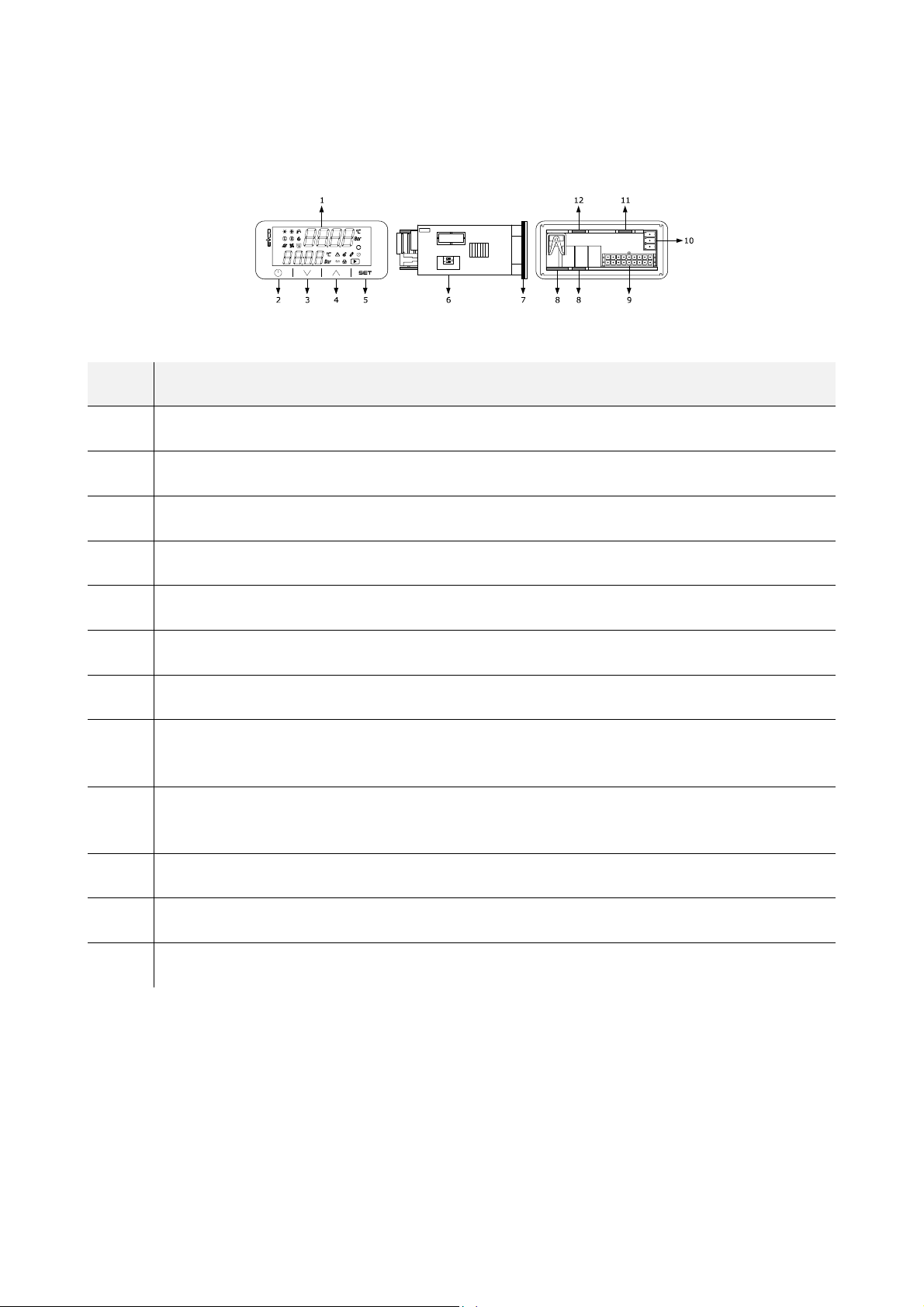
The picture below shows the layout of the EV3 HP.
The table below describes each part of the EV3 HP.
PART DESCRIPTION
1 Double row LED disp lay, with decimal point and function icons
2 On/Off key, subsequently also called the On/Stand-by key
3 Decrease key, subsequently also called the Down key
4 Increase key, subsequently also called the Up key
5 Setting key, subsequently also called the Set key
6 Micro-switch for the termination of the RS-485 MODBUS line
7 Seal
Edge connector joint for the digital output cabling with electro-mechanical relay (for future reference, the digital outputs
8
DO1... DO4)
Male Micro-Fit connector for cabling for the power supply, analogue inputs, digital inputs, analogue outputs and the
9
INTRABUS powered port.
10 If fitted, plug-in screw terminal block for cabling for the RS-485 MODBUS port
11 If fitted, the joint of the Edge connector for the triac digital output cabling (for future reference, the digital output TK1).
12 If fitted, the joint of the Edge connector for the triac digital output cabling (for future reference, the digital output TK2)
For more information see subsequent sections.
page 8 of 52
Page 9
EVCO S.p.A. EV3 HP & EVD HP | Installer manual ver. 1.2 | Code 1443DHPE124
2.2 Description of EVD HP
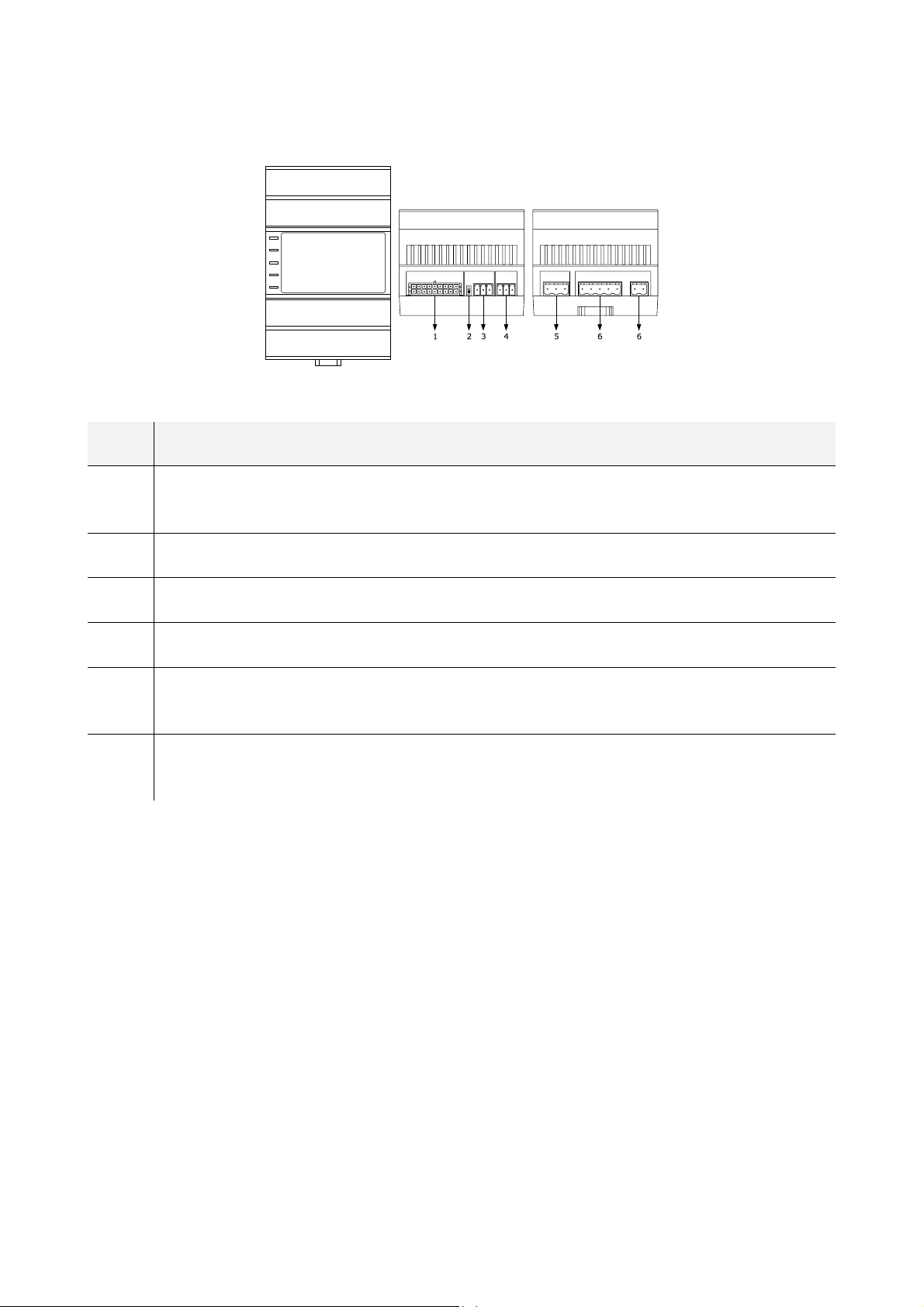
The picture below shows the layout of the EVD HP.
The table below describes each part of the EVD HP.
PART DESCRIPTION
Male Micro-Fit connector for cabling for analogue inputs, digital inputs, analogue outputs and the open collector digital
1
output (for future reference, the digital output OC1)
2 Micro-switch for the termination of the RS-485 MODBUS port
3 If fitted, plug-in screw terminal block for cabling for the RS-485 MODBUS port
4 Plug-in screw terminal block for cabling for the powered INTRABUS port
Plug-in screw terminal block for cabling for the digital outputs with electro-mechanical relay (for future reference, the
5
digital outputs DO1 and DO2)
Plug-in screw terminal block for cabling for the power supply, electrical-mechanica l relay digital outputs (for future
6
reference, the digital outputs DO3 and DO4)
For more information see subsequent sections.
page 9 of 52
Page 10
EVCO S.p.A. EV3 HP & EVD HP | Installer manual ver. 1.2 | Code 1443DHPE124
2.3 Description of EV3K01
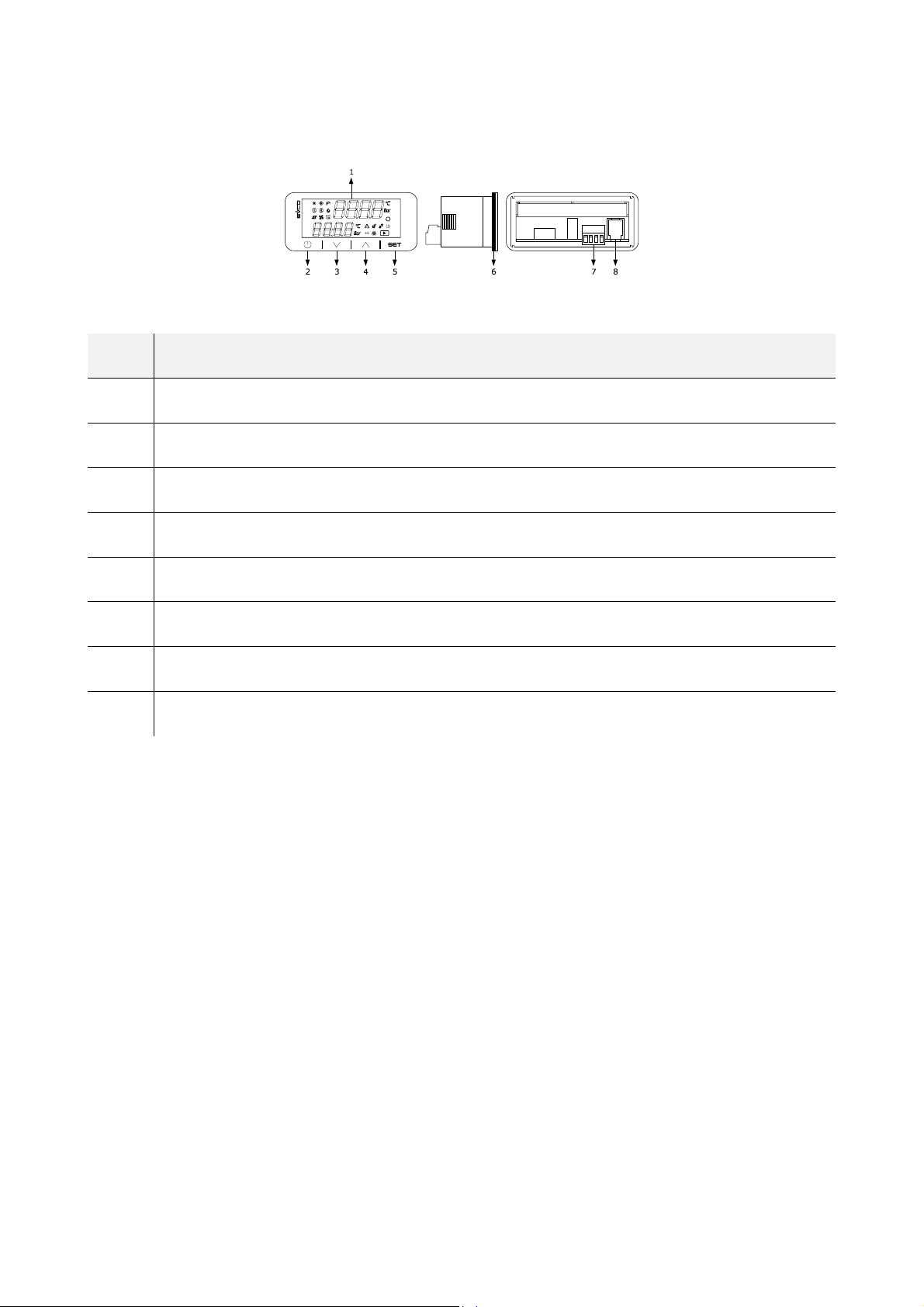
The picture below shows the layout of the EV3K01.
The table below describes each part of the EV3K01.
PART DESCRIPTION
1 Double row LED display, with decima l point and funct ion icons
2 On/Off key, subsequently also called the On/Stand-by key
3 Decrease key, subsequently also called the Down key
4 Increase key, subsequently also called the Up key
5 Setting key, subsequently also called the Set key
6 Seal
7 Male + female plug-in screw terminal block for cabling for the power supply and the powered INTRABUS port
8 Not used
For more information see subsequent sections.
page 10 of 52
Page 11
EVCO S.p.A. EV3 HP & EVD HP | Installer manual ver. 1.2 | Code 1443DHPE124
3 MEASUREMENTS AND INSTALLATION
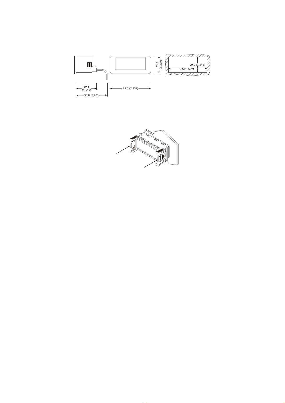
3.1 Measurements and installation of EV3 HP
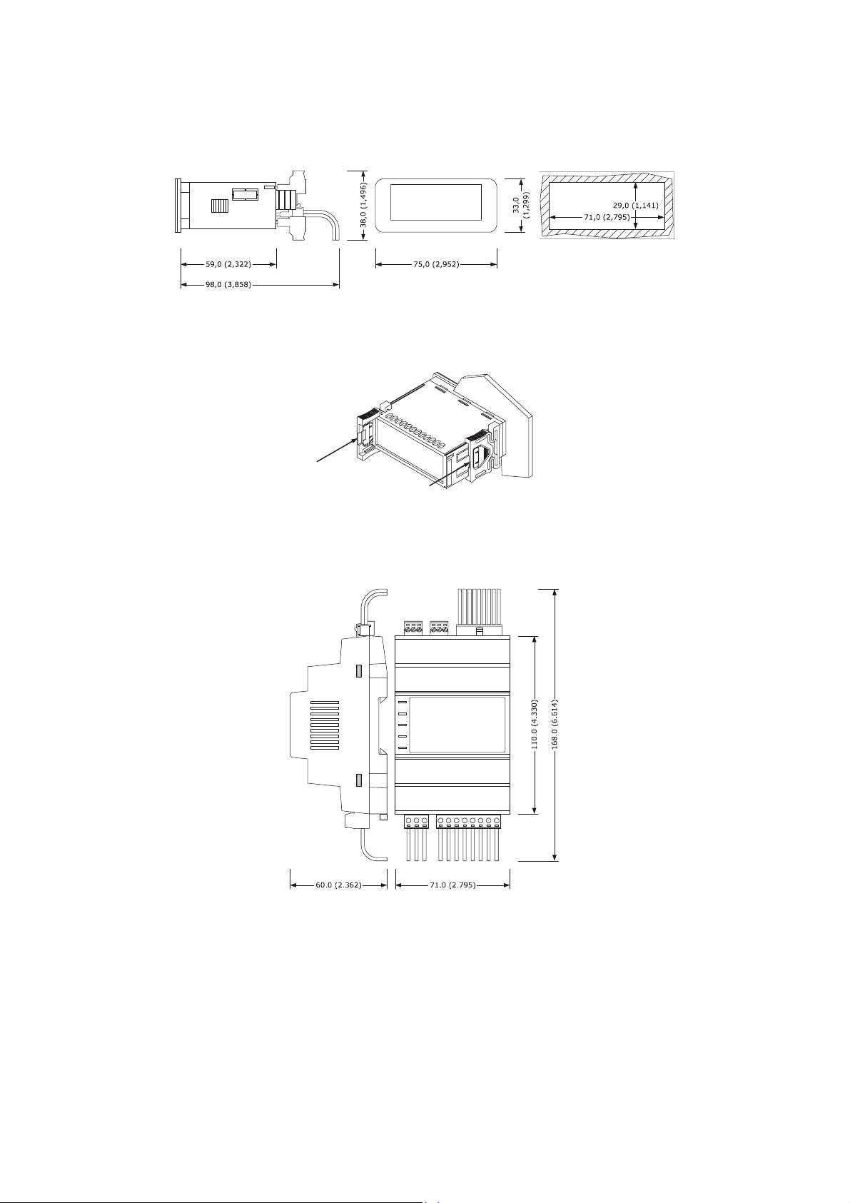
The pictures below show the measurements of EV3 HP; measurements are expressed in mm (inches).
To be installed on a panel with snap-in brackets provided.
The thickness of the panel on which EV3 HP is to be installed must be between 0.8 and 2.0mm (0.031 and 0.078 in).
3.2 Measurements and installation of EVD HP
The picture below shows the measurements of EVD HP (4 DIN modules); measurements are expressed in mm (inches).
page 11 of 52
Page 12
EVCO S.p.A. EV3 HP & EVD HP | Installer manual ver. 1.2 | Code 1443DHPE124
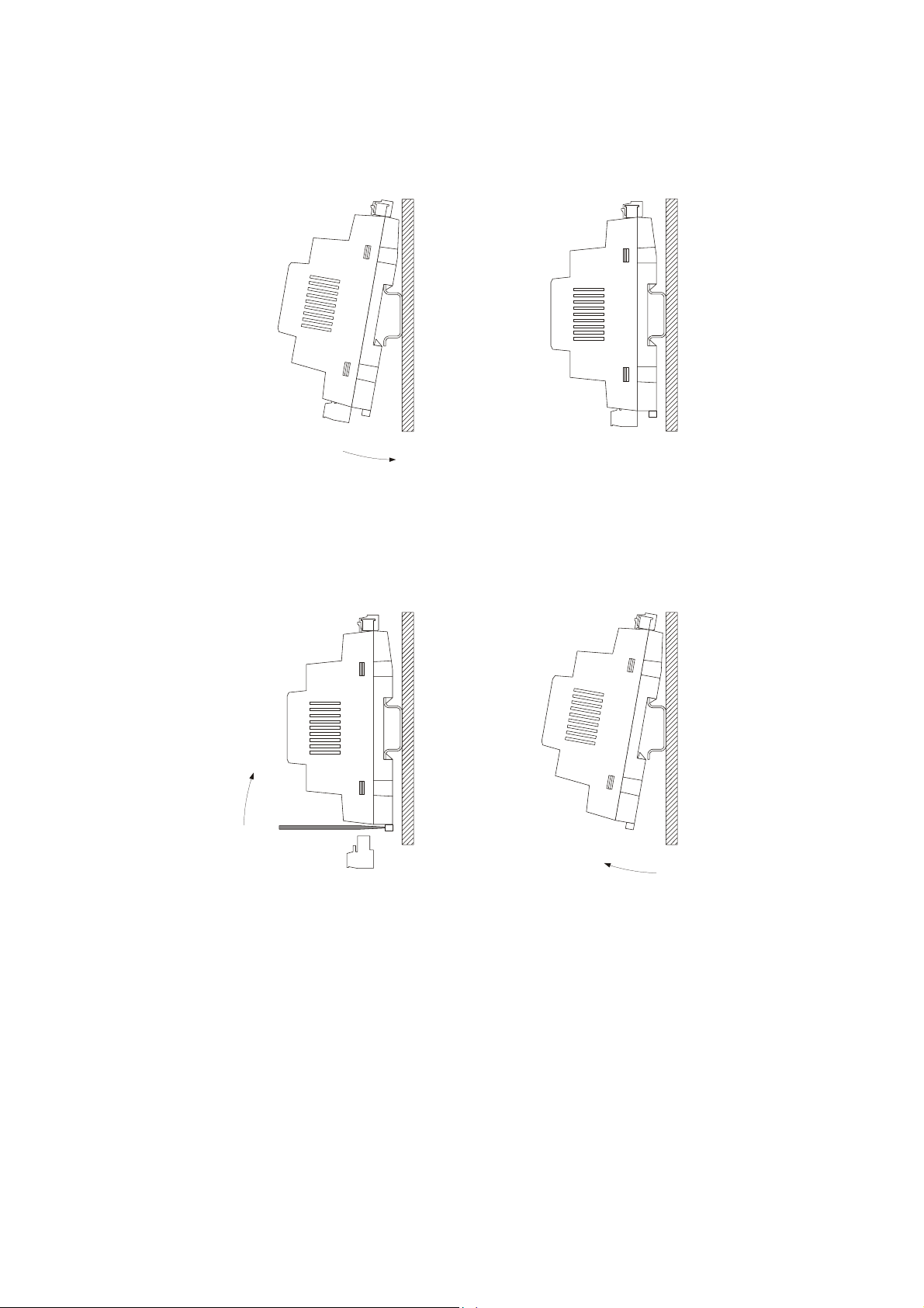
Installation is on a DIN rail 35.0 x 7.5mm (1.377 x 0.295 in) or 35.0 x 15.0mm (1.377 x 0.590 in), in a control panel.
The pictures below show how to install the EVD HP.
1 2
To remove the EVD HP, first remove any plug-in screw terminal blocks fitted in the lower part, then, using a screwdriver, loosen the
DIN rail clip, as shown in the pictures be low.
3 4
To re-install the EVD HP first press the DIN rail clip fully in.
page 12 of 52
Page 13
EVCO S.p.A. EV3 HP & EVD HP | Installer manual ver. 1.2 | Code 1443DHPE124
3.3 Measurements and installation of EV3K01
The pictures below show the measurements of EV3K01; measurements are expressed in mm (inches).
To be installed on a panel with snap-in brackets provided.
The thickness of the panel on which the EV3K01 is to be installed must be between 0.8 and 2.0mm (0.031 and 0.078 in).
3.4 Installation precautions
- Ensure that the working conditions for the devices (operating temperatures, humidity, etc.) are within the set limits. See
the section TECHNICAL SPECIFICATIONS.
- Do not install the devices close to heat sources (heating elements, hot air ducts, etc.), equipment with a strong magnetic
field (large diffusers, etc.), in places subject to direct sunlight, rain, damp, excessive dust, mechanical vibrations or shocks.
- In compliance with safety regulations, the devices must be installed properly to ensure adequate protection from contact
with electrical parts. All protective parts must be fixed in such a way as to need the aid of a tool to remove them.
page 13 of 52
Page 14

EVCO S.p.A. EV3 HP & EVD HP | Installer manual ver. 1.2 | Code 1443DHPE124
4 ELECTRICAL CONNECTION
4.1 I/O configuration
The table below shows the I/O configuration.
ANALOGUE INPUTS EV3914LM2 EV3916LM2GF EVD914BM9
IN1
IN2 Input water temperature (NTC) • • •
IN3 Output water temperature (NTC) • • •
IN4 Compressor discharge temperature (NTC) • • •
IN5 Battery temperature (NTC) • • •
DIGITAL INPUTS EV3914LM2 EV3916LM2GF EVD914BM9
IN10 (EVD)
IN6 (EV3)
IN9 (EVD)
IN7 (EV3)
IN8 Compressor thermal protection (NC) • • •
IN7 (EVD)
IN9 (EV3)
IN6 (EVD)
IN10 (EV3)
Condensation temperature/pressure (NTC/4-20
mA)
System flow switch (NC)
Fan thermal protection
Maximum pressure switch (NC)
Minimum pressure switch (NC)
• • •
• • •
• • •
• • •
• • •
ANALOGUE OUTPUTS EV3914LM2 EV3916LM2GF EVD914BM9
AO1 Compressor (0-10 V/phase cutting/PWM) • • •
AO2 Fan (0-10 V/phase cutting/PWM) • • •
DIGITAL OUTPUTS EV3914LM2 EV3916LM2GF EVD914BM9
DO1 Reversing valve • • •
DO2 Enable fan • • •
DO3 Circulation pump • • •
DO4 Enable compressor • • •
TK1 Boiler/system heating element enable •
TK2 Fan •
OC1 Boiler/system heating element enable •
page 14 of 52
Page 15
EVCO S.p.A. EV3 HP & EVD HP | Installer manual ver. 1.2 | Code 1443DHPE124
4.2 Description of connectors
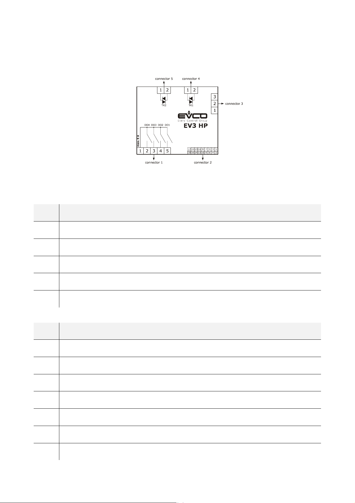
4.2.1 Description of connectors for EV3 HP
The picture below shows the layout of the EV3 HP connectors.
The tables below describe the EV3 HP connectors.
Connector 1
PART DESCRIPTION
1 Electro-mechanical relay digital outputs DO1... DO4 (max. 6A): common
2 Electro-mechanical relay digital output DO4 (2 A SPST): normally open
3 Electro-mechanical relay digital output DO3 (2 A SPST): normally open
4 Electro-mechanical relay digital output DO2 (2 A SPST): normally open
5 Electro-mechanical relay digital output DO1 (2 A SPST): normally open
Connector 2
PART DESCRIPTION
1 Dry contact digital input IN10
2 Analogue input IN1 (NTC/4-20 mA)
3 Dry contact digital input IN9
4 Analogue input IN2 (NTC)
5 Dry contact digital input IN8
6 Analogue input IN3 (NTC)
7 Dry contact digital input IN7
page 15 of 52
Page 16

EVCO S.p.A. EV3 HP & EVD HP | Installer manual ver. 1.2 | Code 1443DHPE124
8 Analogue input IN4 (NTC)
9 Dry contact digital input IN6
10 Analogue input IN5 (NTC)
11 Analogue output AO1 (0-10V/phase cutting/PWM)
12 Reference (GND) for analogue inputs, digital inputs, analogue outputs and powered INTRABUS port
13 Analogue output AO2 (0-10V/phase cutting/PWM)
14 INTRABUS port powered up signal
15 Power supply to analogue inputs 4-20 mA (12 VDC, max. 40 mA)
16 Reference (GND) for analogue inputs, digital inputs, analogue outputs and powered INTRABUS port
17 EV3 HP power supply (12VAC not insulated)
18 EV3 HP power supply (12VAC not insulated)
Connector 3 (if installed)
PART DESCRIPTION
1 RS-485 MODBUS port: +
2 RS-485 MODBUS port: -
3 RS-485 MODBUS port: reference (GND). NB: do not connect the cable shield.
Connector 4 (if installed)
PART DESCRIPTION
1 Triac TK1 output: GND
2 Triac TK1 output (200 mA): OUT
Connector 5 (if installed)
PART DESCRIPTION
1 Triac TK2 output: GND
2 Triac TK2 output (2 A): OUT
page 16 of 52
Page 17
EVCO S.p.A. EV3 HP & EVD HP | Installer manual ver. 1.2 | Code 1443DHPE124
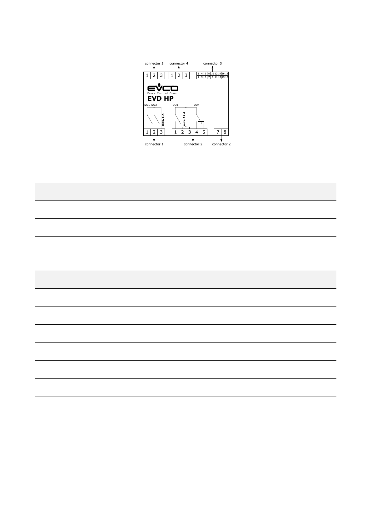
4.2.2 Description of connectors for EVD HP
The picture below shows the layout of the EVD HP connectors.
The tables below describe the EVD HP connectors.
Connector 1
PART DESCRIPTION
1 Electro-mechanical relay digital output DO1 (3A SPST): normally open
2 Electro-mechanical relay digital output DO2 (3A SPST): normally open
3 Electro-mechanical relay digital outputs DO1 and DO2 (max. 6A): common
Connector 2
PART DESCRIPTION
1 Electro-mechanical relay digital output DO3 (12A SPST): normally open
2 Electro-mechanical relay digital output DO3 and D04: common
3 Electro-mechanical relay digital output DO3 and D04: common
4 Electro-mechanical relay digital output DO4 (8A SPDT): normally open
5 Electro-mechanical relay digital output DO4 (8A SPST): normally closed
7 EVD HP power supply (115... 230 VAC insulated)
8 EVD HP power supply (115... 230 VAC insulated)
page 17 of 52
Page 18

EVCO S.p.A. EV3 HP & EVD HP | Installer manual ver. 1.2 | Code 1443DHPE124
Connector 3
PART DESCRIPTION
1 Analogue output AO2 (0-10V/phase cutting/PWM)
2 Analogue outlet AO1 (0-10V/phase cutting/PWM)
3 Reference (GND) for analogue inputs, digital inputs and analogue outputs
4 Analogue input IN1 (NTC/4-20 mA)
5 Dry contact digital input IN10
6 Analogue input IN2 (NTC)
7 Dry contact digital input IN9
8 Analogue input IN3 (NTC)
9 Dry contact digital input IN8
10 Analogue input IN4 (NTC)
11 Dry contact digital input IN7
12 Analogue input IN5 (NTC)
13 Reference (GND) for analogue inputs, digital inputs and analogue outputs
14 Dry contact digital input IN6
15 Reference (GND) for analogue inputs, digital inputs and analogue outputs
16 power supply for analogue inputs 4-20mA (12 VDC, max. 120mA)
17 Open collector digital output OC1 (12V, max. 40mA)
18 Reference (GND) for analogue inputs, digital inputs and analogue outputs
page 18 of 52
Page 19

EVCO S.p.A. EV3 HP & EVD HP | Installer manual ver. 1.2 | Code 1443DHPE124
Connector 4 (if installed)
PART DESCRIPTION
1 RS-485 MODBUS port: reference (GND)
2 RS-485 MODBUS port: -
3 RS-485 MODBUS port: +
Connector 5
PART DESCRIPTION
1 Reference (GND) for EV3K01 power supply powered INTRABUS port
2 INTRABUS port powered up signal
3 EV3K01 power supply
4.2.3 Description of EV3K01 connectors
The picture below shows the layout of the EV3K01 connectors.
The table below describes the EV3K01 connectors.
Connector 1
PART DESCRIPTION
1 EV3K01 (12 VAC/DC) power supply; if EV3K01 is fed by DC power, connect the positive pole
2 Not used
3 INTRABUS port powered up signal
4 Reference (GND) for EV3K01 power supply powered INTRABUS port
page 19 of 52
Page 20
EVCO S.p.A. EV3 HP & EVD HP | Installer manual ver. 1.2 | Code 1443DHPE124
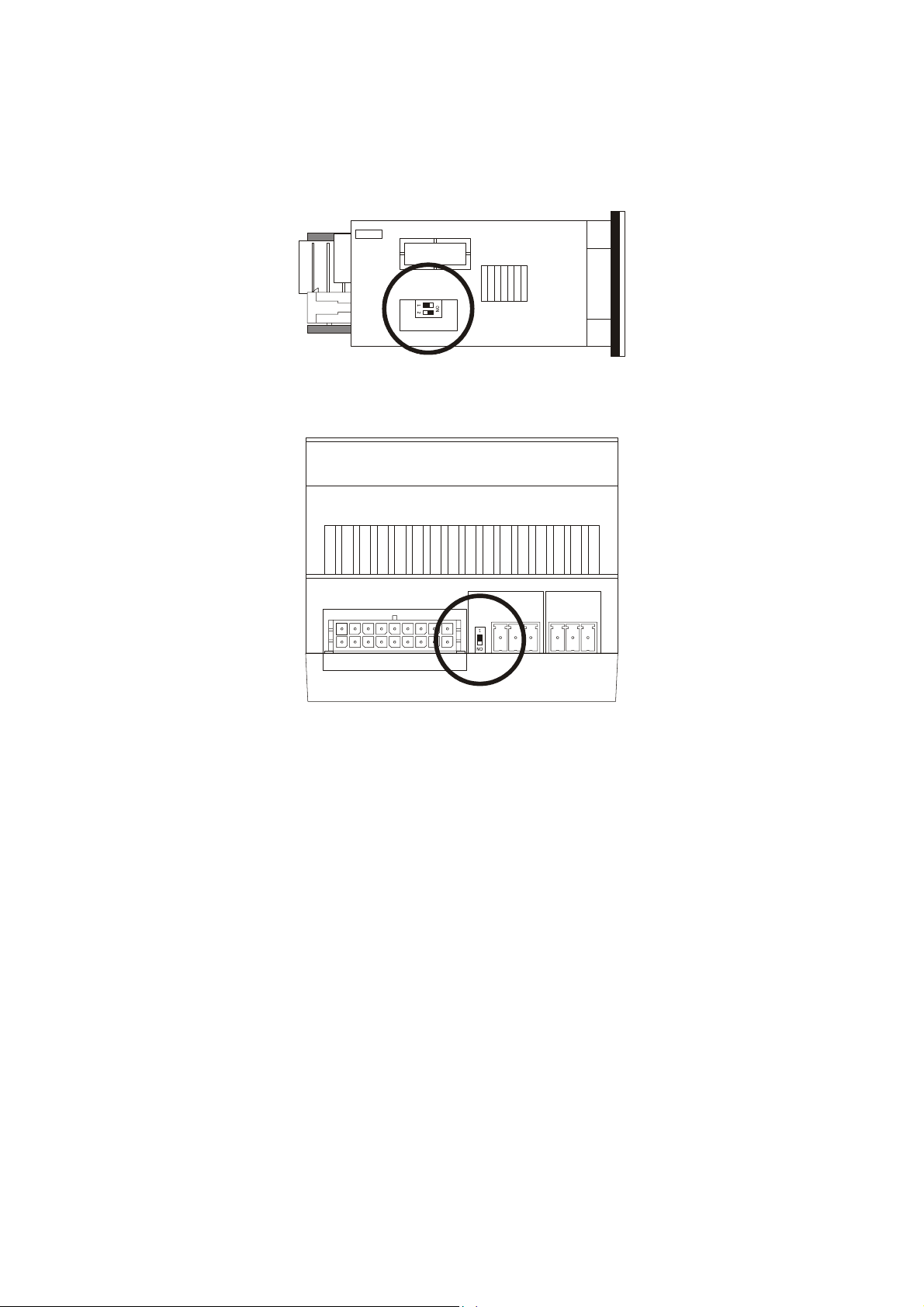
4.3 Termination of the RS-485 MODBUS line
To reduce reflections on the signal transmitted along the cables connecting the devices to a RS-485 network it is necessary to
terminate the line ONLY at the first and last element in the network.
To terminate the line, it will be sufficient to place EV3 HP micro-switch 1 in position ON. Do not touch micro-switch 2.
When using EVD HP, place micro-switch 1 in posit ion ON.
page 20 of 52
Page 21
EVCO S.p.A. EV3 HP & EVD HP | Installer manual ver. 1.2 | Code 1443DHPE124
4.4 Example of electrical connection
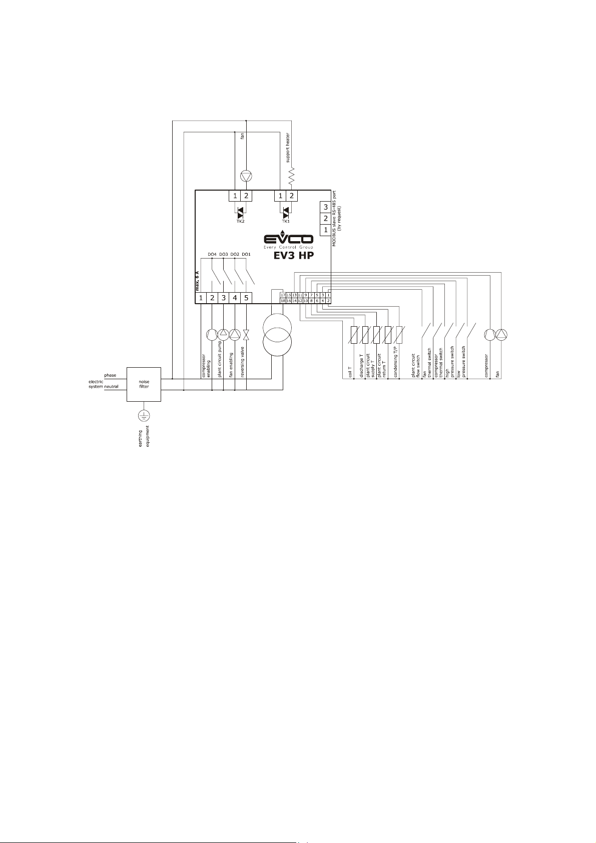
4.4.1 Example of EV3 HP electrical connection
The picture below shows an example of the EV3 HP electrical connection.
If using triac digital outputs, we recommend connecting a noise filter. The heat sink might reach very high temperatures, do not touch
it.
page 21 of 52
Page 22
EVCO S.p.A. EV3 HP & EVD HP | Installer manual ver. 1.2 | Code 1443DHPE124
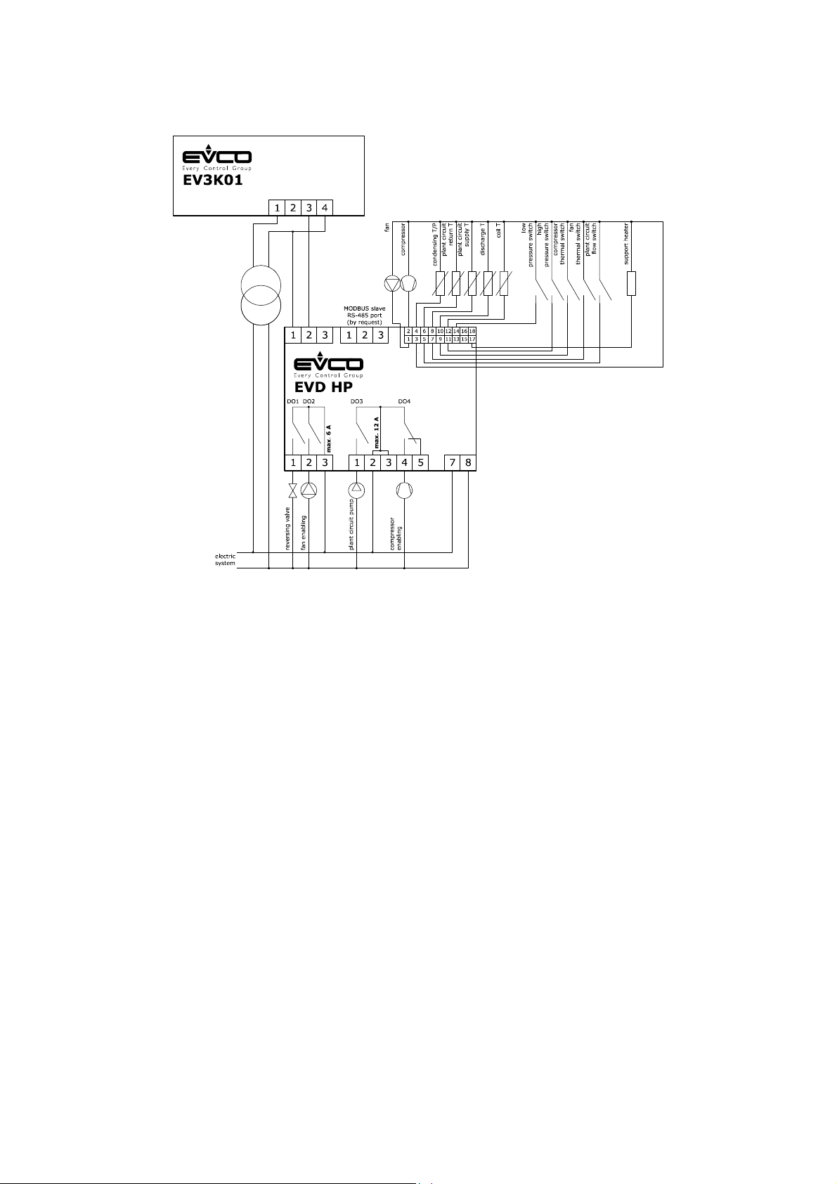
4.4.2 Example of EVD HP electrical connection
The picture below shows an example of the EVD HP electrical connection.
page 22 of 52
Page 23

EVCO S.p.A. EV3 HP & EVD HP | Installer manual ver. 1.2 | Code 1443DHPE124
4.5 Precautions for electrical connection
- Do not use electric or pneumatic screwdrivers on the terminal blocks of the devices.
- If the devices have been moved from a cold to a warm place, the humidity may cause condensation to form inside. Wait
about an hour before switching on the power.
- Make sure that the supply voltage, electrical frequency and power of the devices correspond to the local power supply. See
the section TECHNICAL SPECIFICATIONS.
- Disconnect the devices from the power supply before doing any type of maintenance.
- The devices must be fed by power of the same phase as that feeding any module with a phase-cutting command signal.
- If using triac digital outputs, we recommend connecting a noise filter. The heat sink might reach very high temperatures,
do not touch it.
- Connect the devices to an RS-485 network using a screened cable with twisted pair for the signal and a third separate
conductor for the reference (for example the BELDEN 3106A cable). NB: do not connect the cable shield to the reference
(GND)
- Connect the power cables as far away as possible from those for the signal.
- Do not use the devices as safety devices.
- For repairs and for further information on the devices, contact the EVCO sales network.
page 23 of 52
Page 24
EVCO S.p.A. EV3 HP & EVD HP | Installer manual ver. 1.2 | Code 1443DHPE124
5 DESCRIPTION OF USER INTERFACE
5.1 Key functions
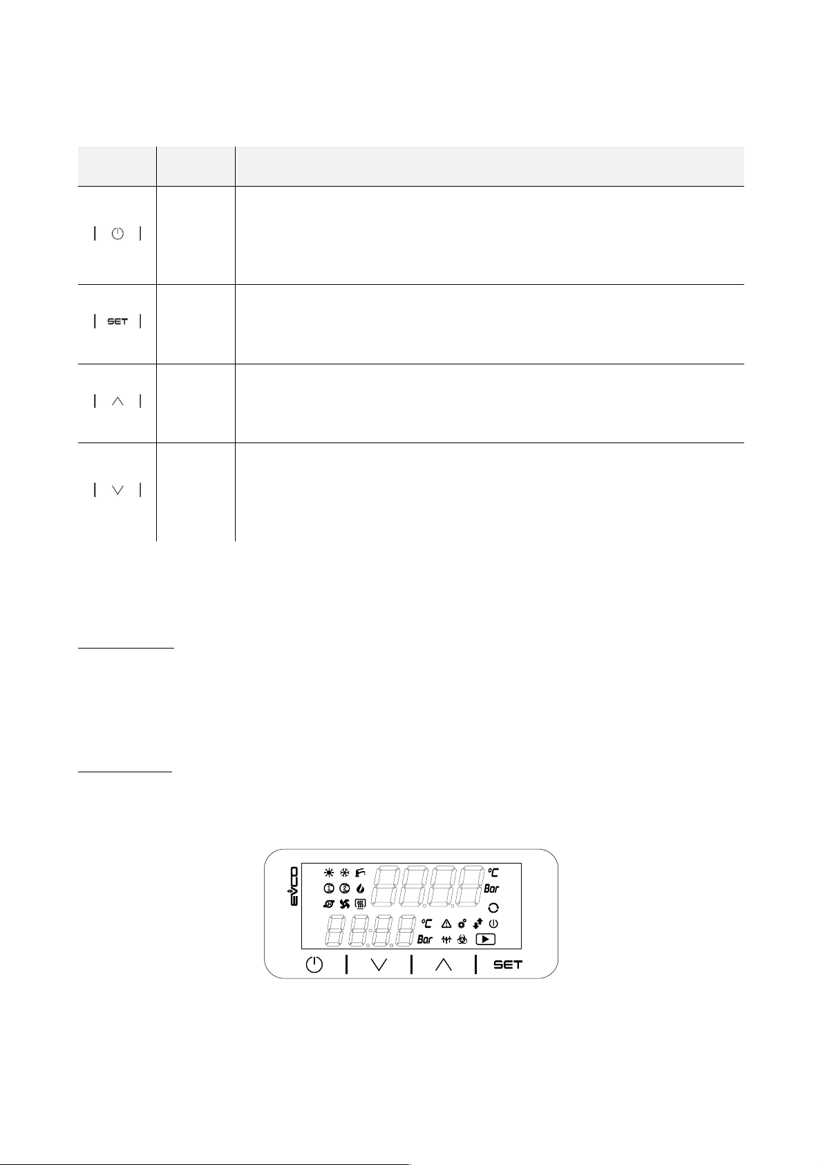
The table below shows the functions of the keys.
ICON NAME FUNCTION
- Prolonged pressure will switch the device on or off.
On/stand-by
Set
Up
- While setting the parameters, it functions as a “Back” key.
- The system function mode is modified every time this key is pressed according to the
sequence cold hot
- Prolonged pressure makes it possible to enter or exit the set-up menu (SEtP menu)
- Press once to modify the set-point and confirm it.
- It functions as the “Enter” key in menu navigation.
In set-parameters mode:
- It enables you to move to a higher menu
- It enables you to increase the value of a parameter
In set-parameters mode:
Down
- It enables you to move to a lower menu
- It enables you to decrease the value of a parameter
- Prolonged pressure enables you to view the measurements found by the probes.
5.2 Display
A pressure on the On/ stand-by will switch on / switch off the device. When the device is switched on with the key, it is possible to
switch it remotely to Stand-By mode by operating on the dedicated digital input through a switch.
The user interface has two display modes.
Initial displa y mode
- The upper row shows the input water temperature, while the lower row shows the output water temperature or any alarms
activated.
- When the device is switched on with the key but remotely put to Stand-By mode, the label “oFFd” will be displayed on the
lower row.
- When the device is switched off with the key, the label “OFF” will be displayed on the upper row, while the time will be
displayed on the lower row (if RTC is present and enabled, otherwise 4 lines ---- will be displayed.
Menu display mode
- What is displayed depends upon the menu level you are in, using a directory tree system in which the lower row shows a
subcategory of the one shown on the upper row. To help users to identify what is being displayed, labels and codes are
used, see paragraph 5.4.2.
page 24 of 52
Page 25
EVCO S.p.A. EV3 HP & EVD HP | Installer manual ver. 1.2 | Code 1443DHPE124
5.3 Signals
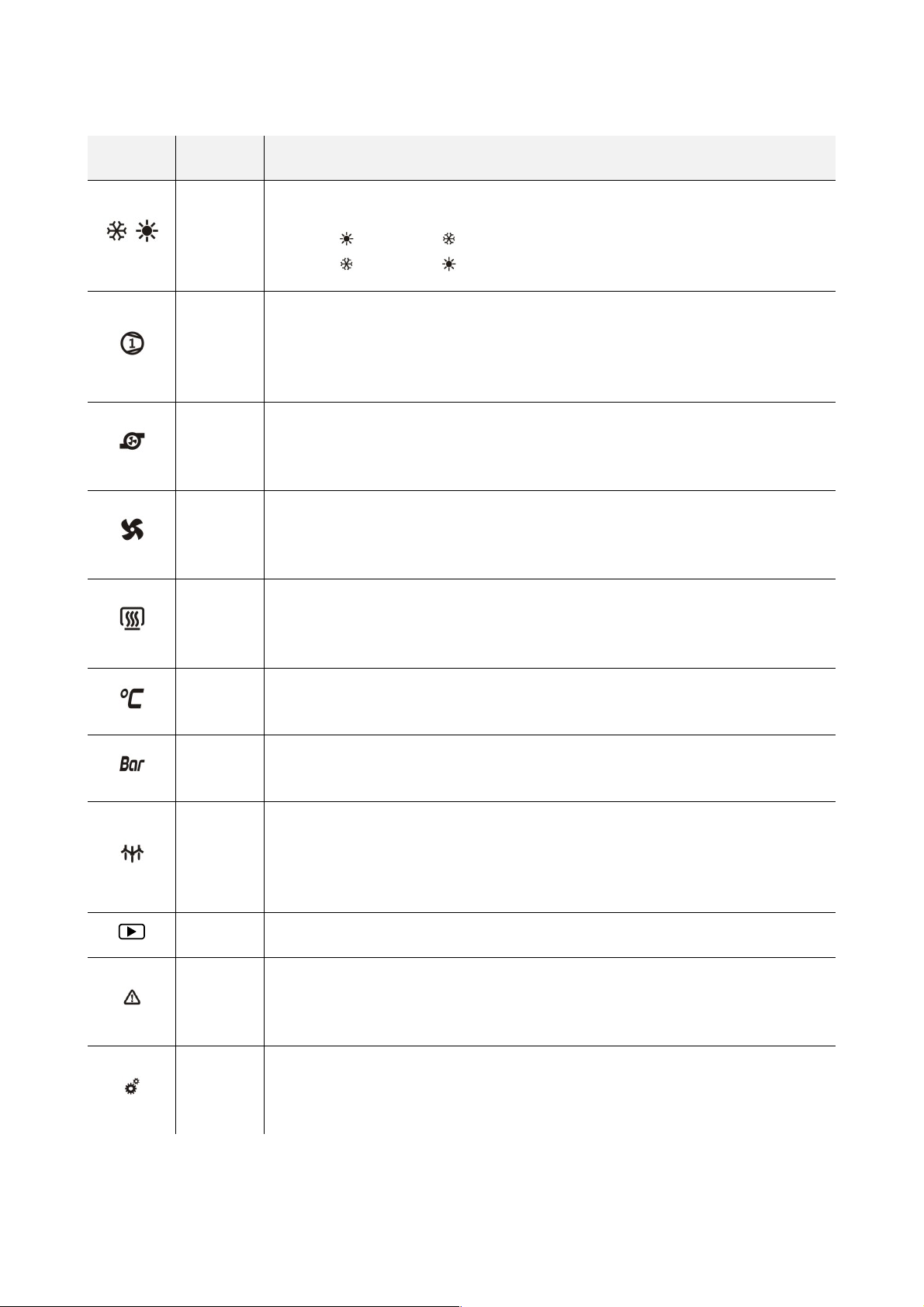
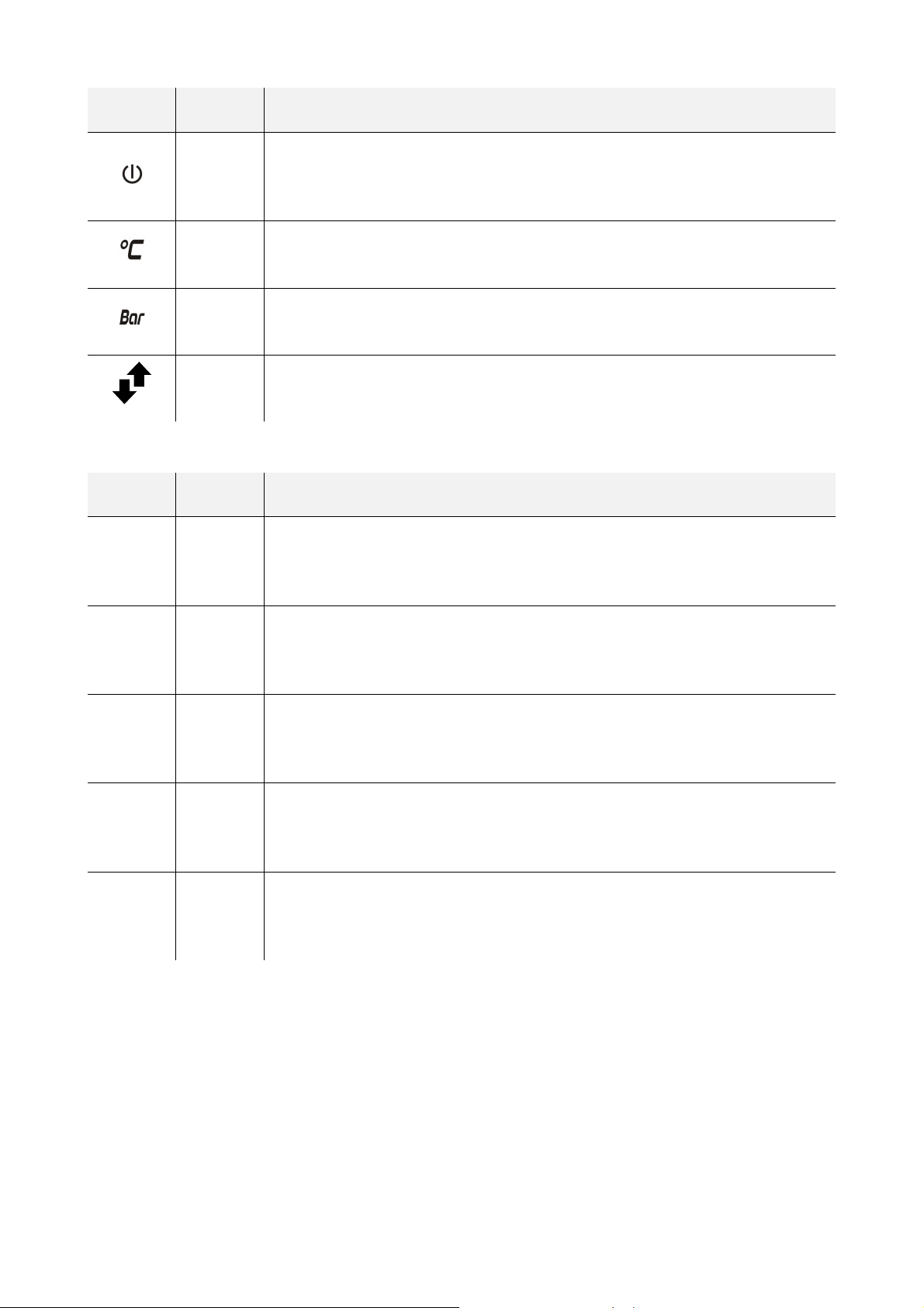
The table below shows the meaning of the LED signals of EV3 HP.
LED COLOUR DESCRIPTION
Controller LED
Dependant on parameter CF06 (default 0)
0
1
Compressor LED
- ON if the compressor is switched on
- OFF if the compressor is switched off
- BLINK if some timings are underway
Hydraulic pump LED
- ON if the pump is switched on
- OFF if the pump is switched off
= heating ON / = chilling ON
= heating ON / = chilling ON
GREEN
GREEN
GREEN
Condenser fan LED
GREEN
GREEN
AMBER
AMBER
AMBER
AMBER Run LED
- ON if the fan is switched on
- OFF if the fan is switched off
System heating element LED
- ON if the heating element is switched on
- OFF if the heating element is switched off
LED for the unit of measurement of the value shown on the lower display when the probe is
configured for temperature
LED for the unit of measurement of the value shown on the lower display when the probe is
configured for pressure
Defrost LED
- OFF if defrosting is underway
- OFF if defrosting is not in progress or is completed
- BLINK (1 sec) if some timings are underway for the defrost start or if the dripping is
underway
Alarm LED
RED
RED
- ON if an alarm is underway
- OFF if no alarm is underway
Set-up LED
- ON if the device is not showing the initial display
- OFF during normal functioning
page 25 of 52
Page 26
EVCO S.p.A. EV3 HP & EVD HP | Installer manual ver. 1.2 | Code 1443DHPE124
LED COLOUR DESCRIPTION
On/stand-by LED
- OFF if the controller is switched off (at the same time the “OFF” label will be displayed)
RED
- OFF if the controller is switched on
RED
RED
RED
LED for the unit of measurement of the value shown on the upper display when the probe is
configured for temperature
LED for the unit of measurement of the value shown on the upper display when the probe is
configured for pressure
IB/RS485 LED
- BLINK if an INTRABUS/RS485 communication is underway
- OFF if no communication is underway
The table below shows the meaning of the LED signals of EVD HP.
LED COLORE SIGNIFICATO
Power supply LED
ON GREEN
RUN GREEN
- ON if the controller is powered
- OFF if the controller is not powered
“RUN” LED
- ON if the controller is switched on
- OFF if the controller is switched off
∆ RED
IB AMBER
RS485 AMBER
Alarm LED
- ON if an alarm is underway
- OFF if no alarm is underway
INTRABUS LED
- BLINK if an INTRABUS communication is underway
- OFF if no communication is underway
RS-485 LED
- BLINK if an RS-485 communication is underway
- OFF if no communication is underway
page 26 of 52
Page 27

EVCO S.p.A. EV3 HP & EVD HP | Installer manual ver. 1.2 | Code 1443DHPE124
5.4 Menu
5.4.1 Access levels
There are three access levels for navigating within the menus, two of which require a password:
U User: always visible
S Servicer: visible if the servicer password (parameter CF09, default -12) or the manufacturer password (parameter CF10,
default -123) have been entered
M Manufacturer: visible if the manufacturer password (parameter CF10, default -123) has been entered.
5.4.2 Menu list
The following menus are available:
SEtP For rapid access to the adjustment set-points
Prob Shows the temperature or pressure values for the inputs configured as probes
ALAr Shows the list of alarms underway
di Shows the status of the inputs configured as digital inputs
Ao Shows the status of the outputs configured as analogue outputs or as triac/open collector
do Shows the status of the outputs configured as digital outputs
PAr Shows and allows the device parameters to be altered. The parameters are grouped according to their function, identified
on the display by a label. Each parameter has an alphabetic code followed by two numbers, as shown in the table below.
GROUP IDENTIFICATION LABEL PARAMETER CODE
Configuration ConF CF
Compressor CoMP CP
Fan FAn Fn
Alarms ALAr AL
Adjustment rEGL rL
Pump PUMP PM
Electric heat ing ele ments Fro Fr
Defrost dFr dF
Offset OFF oF
OHr Shows the time the compressors (OH1 and OH2) and the pump (OHP) have been functioning.
HiSt In devices fitted with a clock, up to 20 alarm events can be stored in the memory. The history and details of these are
shown on the lower displa y in the following sequence.
y xx year
M xx month
d xx day
hh:mm hours:minutes
rtC The time can be set on devices fitted with a clock.
inFo Shows the FW version (project, variation and revision)
PASS The password is entered for access to the desired level: parameter Cf09 for servicer level, Cf10 for manufacturer level.
page 27 of 52
Page 28
EVCO S.p.A. EV3 HP & EVD HP | Installer manual ver. 1.2 | Code 1443DHPE124
6 LIST OF PARAMETERS
6.1 Initial information
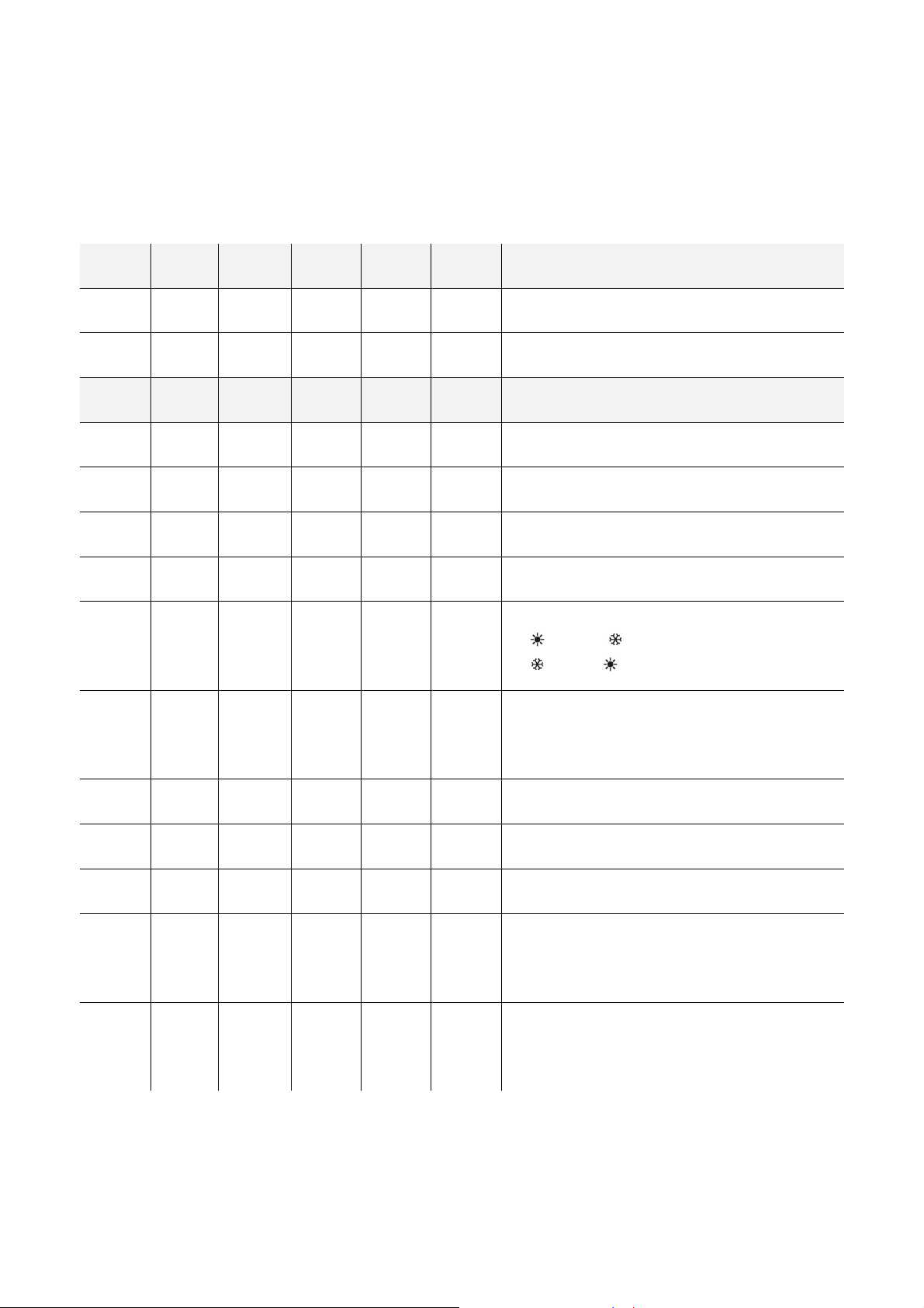
The three levels of access to the parameters are shown in the first column of the following table with letters:
U User
S Servicer
M Manufacturer
For more information see the previous paragraph 5.4.
MENU PARAM. DEFAULT MIN. MAX. U.M. SET-POINT
U CooL 8,5 CF04 CF03 °C Temperature set-point in cold mode
U HEAt 40,0 CF02 CF01 °C Temperature set-point in hot mode
MENU PARAM. DEFAULT MIN. MAX. U.M. CONFIGURATION
S CF01 60,0 HEAt 90.0 °C Maximum set-point value in hot mode
S CF02 20,0 0.0 HEAt °C Minimum set-point value in hot mode
S CF03 30,0 CooL 90.0 °C Maximum set-point value in cold mode
S CF04 4,0 -50.0 Cool °C Minimum set-point value in cold mode
Controller LED meaning
M CF06 0 0 1 - - - -
S CF07 1 0 1 - - - -
S CF08 1 1 200 - - - - MODBUS serial address
S CF09 -12 -127 127 - - - - Servicer password
M CF10 -123 -127 127 - - - - Manufacturer password
M CF13 1 0 1 - - - -
0=
= heating / = cooling
1=
= heating = cooling
Enable clock
0=Off
1= On
Enable hot mode
0= Off
1= On
M CF14 1 0 1 - - - -
page 28 of 52
Enable cold mode
0= Off
1= On
Page 29

EVCO S.p.A. EV3 HP & EVD HP | Installer manual ver. 1.2 | Code 1443DHPE124
IN1 output configuration type
0= Temperature [°C]
M CF17 0 0 2 - - - -
M CF31 0,0 -50,0 80,0 Bar Start of condensation pressure scale
M CF32 50,0 -50,0 80,0 Bar Bottom of condensation pressure scale
M CF35 2 0 4 - - - -
1= 4-20mA [Bar]
2= Not used
The choice of CF17 value determines the unit of
measurement for the condensation (°C or Bar)
AO1 output configuration type
0= Disabled
1= Phase cutting [%]
2= 0-10V [%]
3= PWM [%]
4= Frequency [Hz]
The choice of CF35 value determines the unit of
measurement for adjusting the compressor (Hz or %)
AO2 output configuration type
0 = Disabled
1= Phase cutting [%]
M CF36 1 0 4 - - - -
M CF47 0 0 4 - - - -
S CF51 0 0 1 - - - -
MENU PARAM. DEFAULT MIN. MAX. U.M. ALARMS
2= 0-10V [%]
3= PWM [%]
4= Frequency [Hz]
The choice of CF36 value determines the unit of
measurement for adjusting the fan (Hz or %)
AO1 analogue output function configuration
0= Disabled
1= Not used
2= Not used
3= Not used
4= Modulating compressor
RUN Logo
0= Off
1= On
M AL01 3 0 255 - - - -
M AL02 120 0 255 s Low pressure alarm bypass time
M AL03 -20,0 -50.0 80.0 °C-Bar Low pressure alarm set-point
page 29 of 52
Number of alarms in an hour for low pressure after which
the alarm switches from automatic to manual re-arm
Page 30

EVCO S.p.A. EV3 HP & EVD HP | Installer manual ver. 1.2 | Code 1443DHPE124
M AL04 10,0 -12.7 12.7 °C-Bar Low pressure alarm hysteresis
M AL05 65,0 -50.0 80.0 °C-Bar High pressure alarm set-point
M AL06 25,0 -12.7 12.7 °C-Bar High pressure alarm hysteresis
M AL07 5 0 255 - - - -
M AL08 30 0 255 s Bypass time for flow alarm from pump activation
M AL09 3 0 255 s Flow alarm delay from activating flow switch input
M AL10 5 0 255 s
S AL12 3,0 -127 127 °C Antifreeze alarm set-point
S AL13 2,0 0.0 25.5 °C Antifreeze alarm hysteresis
M Al14 0 0 1 - - - -
M AL15 99 0,0 255,0 °C High adjustment temperature alarm set-point
Number of flow alarm events in an hour after which the
alarm switches from automatic to manual re-arm
Flow alarm re-arm delay from deactivating flow switch
input
Stop fan with antifreeze alarm
0= Disabled
1= Enabled
M AL16 5 0 255 s*10 High adjustment temperature alarm delay
M Al17 105,0 0,0 255,0 °C High discharge temperature alarm set-point
M AL18 15,0 0.0 25.5 °C High discharge temperature alarm hysteresis
MENU PARAM. DEFAULT MIN. MAX. U.M. COMPRESSOR
M CP01 6 0 255 s*10 Compressor OFF minimum time
M CP02 36 0 255 s*10 Compressor successive switch-ons minimum time
M CP05 20 10 CP06 Hz - % Minimum modulating compressor value
M CP06 100 CP05 255 Hz - % Maximum modulating compressor value
Cut-off hysteresis for modulating compressor adjustment
M CP08 0,0 0.0 25.5 °C
M CP09 40 0 255 Hz - % Set-point for refreshing the modulating compressor oil
(“CooL” and “HEAt”)
For ON-OFF adjustment set to 0
page 30 of 52
Page 31

EVCO S.p.A. EV3 HP & EVD HP | Installer manual ver. 1.2 | Code 1443DHPE124
M CP10 5 0 255 min Delay for refreshing the modulating compressor oil
MENU PARAM. DEFAULT MIN. MAX. U.M. COMPRESSOR ADJUSTMENT
S rL01 5,0 0.0 25.5 °C Compressor proportional adjustment band in cold mode
S rL02 5,0 0.0 25.5 °C Compressor proportional adjustment band in hot mode
S rL04 0 0 255 s*10 Compressor adjustment integral time
MENU PARAM. DEFAULT MIN. MAX. U.M. VENTILATION
M Fn01 20 0 255 s/10
M Fn02 1 0 10 ms/2 Fan phase shift
M Fn03 1 0 1 - - - -
M Fn04 3,0 0.0 25.5 °C-Bar Fan adjustment delta cut-off
M Fn05 2,0 0 25.5 °C-Bar Fan cut-off hysteresis
M Fn06 20 0 255 s Fan cut-off bypass time
M Fn07 30 0 100 Hz - % Minimum fan speed in cold mode
M Fn08 100 0 100 Hz - % Maximum silent-running fan speed in cold mode
M Fn09 30,0 -50.0 80.0 °C-Bar Set-point temp/press minimum fan speed in cold mode
Fan start-up time, if CF36 is set to 1 (AO2 output
configuration type = phase cutting)
Fan mode
0= On-call (at the request of the compressor)
1= Independent
M Fn10 20,0 0.0 25.5 °C-Bar Fan proportional adjustment band in cold mode
M Fn11 100 0 100 Hz - % Maximum fan speed in cold mode
M Fn12 57,0 -50.0 80.0 °C-Bar Maximum fan speed set-point in cold mode
M Fn13 30 0 255 s Pre-ventilation time in cold mode
M Fn14 30 0 100 Hz - % Minimum fan speed in hot mode
M Fn15 100 0 100 Hz - % Maximum silent-running fan speed in hot mode
M Fn16 9,0 -50,0 80,0 °C-Bar Minimum fan speed set-point in hot mode
M Fn17 6,0 0,0 25,5 °C-Bar Fan proportional adjustment band in hot mode
page 31 of 52
Page 32

EVCO S.p.A. EV3 HP & EVD HP | Installer manual ver. 1.2 | Code 1443DHPE124
M Fn18 100 0 100 Hz - % Maximum fan speed in hot mode
M Fn19 0,0 -50,0 80,0 °C-Bar Maximum fan speed set-point in hot mode
M Fn20 50,0 -50,0 80,0 °C-Bar Fan activation set-point in defrost mode
M Fn21 10,0 0,0 25,5 °C-Bar Fan activation hysteresis in defrost mode
M Fn23 30 0 255 Hz - % Fan speed in defrost mode
MENU PARAM. DEFAULT MIN. MAX. U.M. PUMP
M PM01 20 0 255 s Compressor switch-on delay from pump switch-on
M PM02 10 0 255 s Pump switch-off delay from compressor switch-off
Pump ON mode at request
M PM03 1 0 1 - - - -
0= disabled (pump on constantly)
1= enabled
S PM04 4 -127 127 °C Antifreeze set-point for activating pump
S PM05 2,0 0.0 25.5 °C Antifreeze hysteresis for activating pump
MENU PARAM. DEFAULT MIN. MAX. U.M. HEATING ELEMENTS
S Fr02 6 Fr04 Fr03 °C Heating element set-point (for antifreeze)
M Fr03 10 Fr04 127 °C Maximum heating element set-point (for antifreeze)
M Fr04 -10 -127 Fr03 °C Minimum heating element set-point (for antifreeze)
S Fr05 2,0 0,0 25,5 °C Heating element hysteresis in integration mode
M Fr11 180 0 255 s*10 Heating element activation delay in integration mode
M Fr12 6,0 0,0 25,5 °C Heating element delta temperature in integration mode
MENU PARAM. DEFAULT MIN. MAX. U.M. DEFROST
Enable defrost
0 = disabled
1 = with activated compressor
M dF01 1 0 3 - - - -
2 = for compressor stop (similar to dF01 = 1 but without
activating the compressor)
3 = Time interval defrost (similar to dF01 = 1 but ending
up for exceeded time
M dF02 -5,0 -50.0 80.0 °C-Bar Defrost start set-point
page 32 of 52
Page 33

EVCO S.p.A. EV3 HP & EVD HP | Installer manual ver. 1.2 | Code 1443DHPE124
M dF03 20 0 255 min Defrost activation delay
M dF04 15,0 -50.0 80.0 °C Defrost end set-point
M dF05 5 0 255 min Maximum defrost time
M dF06 60 0 255 s
M dF07 6 0 255 s*10 Dripping time
M dF09 3 0 255 s*10 Compressor switch-on delay in defrost mode
MENU PARAM. DEFAULT MIN. MAX. U.M. PROBE OFFSET
S oF01 0,0 -12.7 12.7 °C-Bar Offset analogue input 1 (IN1)
S oF02 0,0 -12.7 12.7 °C Offset analogue input 2 (IN2)
S oF03 0,0 -12.7 12.7 °C Offset analogue input 3 (IN3)
S oF04 0,0 -12.7 12.7 °C Offset analogue input 4 (IN4)
S oF05 0,0 -12.7 12.7 °C Offset analogue input 5 (IN5)
Waiting time between compressor switching and reversing
valve switching
7 REGULATORS
7.1 Initial information
The CF06 parameter makes it possible to configure the meaning of the sun and snowflake LEDs according to the following coding.
- CF06 = 0
- CF06 = 1
= heating / = cooling
= heating / = cooling
7.2 Function mode
The following function modes are available
- Parameter CF13 enables the Heating function
- Parameter CF14 enables the Cooling function
If neither mode is enabled, the unit will in Cooling mode.
The function mode can be selected on the keypad: to move from one mode to another, simply press the On/Standby key.
7.3 Compressor
The adjustment is based on the value provided by the input water probe. The compressor is run on the basis of this temperature and of
the set-point.
If a modulating compressor is to be used, connect it to analogue output AN1, in which case it will be adjusted by a proportional-integra l
controller (PI). Output DO4 provides the enable signal to the modulating compressor DO4. In order for the enable signal to be
synchronised with the compressor control signal, parameter CP08 must be other than 0.
Parameter CP01 determines the minimum time between the compressor switch-off and its successive switch-on, while parameter CP02
determines the minimum time between two successive switch-ons (that is to say the maximum number of switch-ons per hour).
Parameters CP05 and CP06 have a different meaning depending on the type of analogue output, selected by parameter CF35: if the
output is a frequency, they represent the maximum and minimum working frequencies, otherwise they represent the maximum and
minimum working percentages.
If ON-OFF type compressors are to be used, parameter CP08 must be set at 0. Compressor is connected to output DO4.
page 33 of 52
Page 34
EVCO S.p.A. EV3 HP & EVD HP | Installer manual ver. 1.2 | Code 1443DHPE124
7.3.1 Adjustment in cold mode
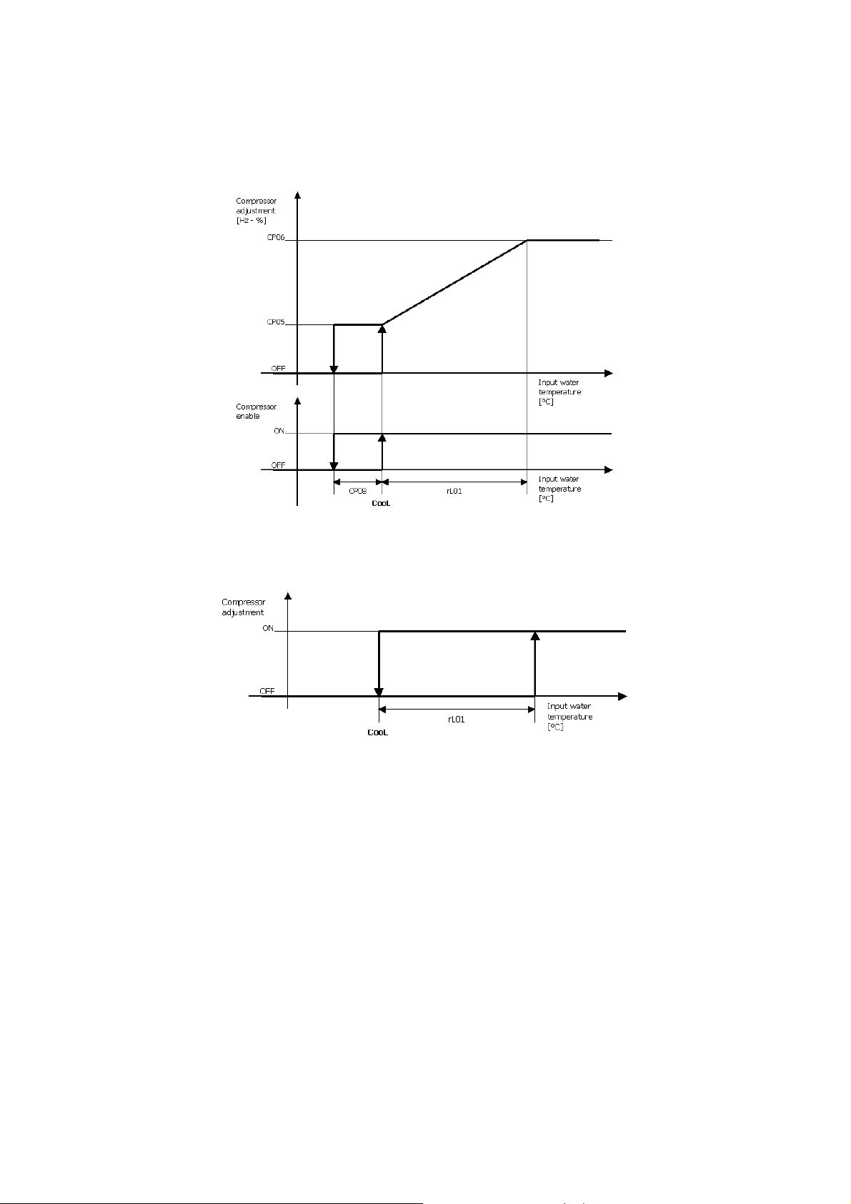
The regulators can work in cold (chiller) mode if parameter CF14 is configured correctly.
The diagram below represents the proportional adjustment in cold mode. To keep it simple, the integral component is not represented
(Rl04 = 0). The compressor enable outlet is also shown.
For ON-OFF adjustment, the cut-off delta must be set to 0 and there will be only one adjustment step, as shown on the diagram below.
page 34 of 52
Page 35
EVCO S.p.A. EV3 HP & EVD HP | Installer manual ver. 1.2 | Code 1443DHPE124
7.3.2 Adjustment in hot mode
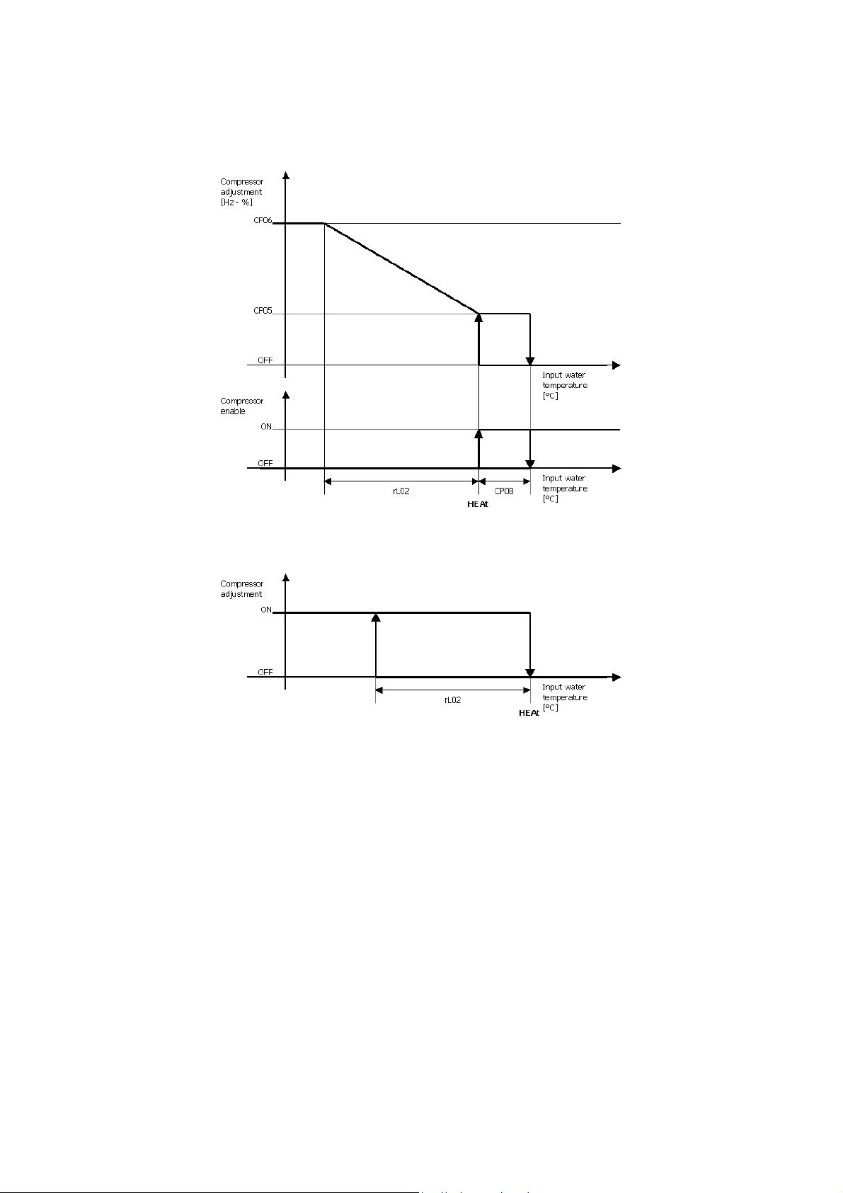
The regulators can work in hot (he at pump) mode if parameter CF13 is configured correctly.
The diagram below represents the proportional adjustment in hot mode. The integral component is not represented (Rl04 = 0).
For ON-OFF adjustment, the cut-off delta must be set to 0 and there will be only one adjustment step, as shown on the diagram below.
7.3.3 Oil refresh
If the compressor is running at a frequency lower that the CP09 parameter for a period longer than the CP10 parameter, it is activated
at the maximum frequency. The compressor will remain at the maximum power until it reaches the set-point.
page 35 of 52
Page 36
EVCO S.p.A. EV3 HP & EVD HP | Installer manual ver. 1.2 | Code 1443DHPE124
7.4 Hydraulic pump
7.4.1 Initial information
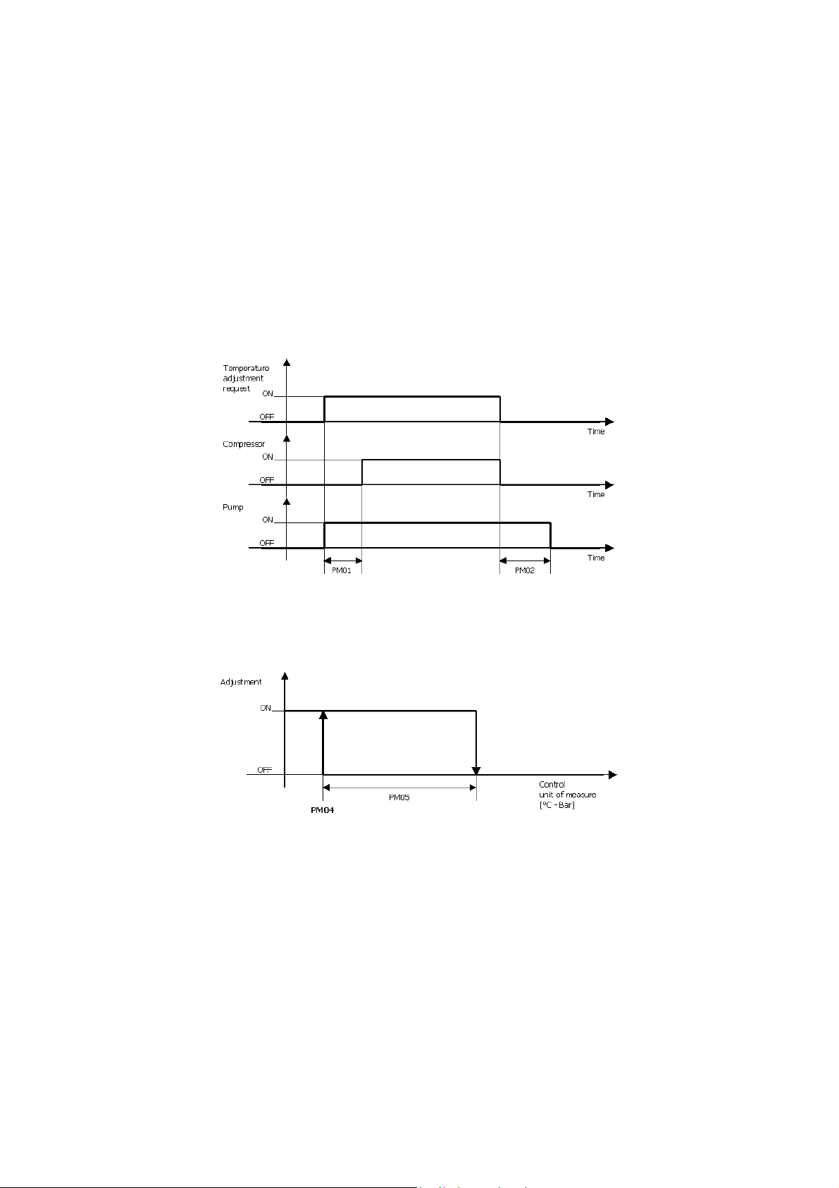
The functional mode of the hydraulic pump can be set using parameter Pm03: the pump may be always kept switched on or be
switched on for thermoregulation in relation to the functioning of the compressor.
In the second case, the pump switches off after a delay of PM02 from when the compressor is switched off every time it is deactivated
by the regulator. It will switch off immediately if an alarm sounds requiring the pump to be stopped, as for the flow alarm in manual re-
arm (with the flow alarm active in automatic re-arm, the pump stays switched on).
7.4.2 Function modes
The hydraulic pump can be set to function in two modes.
Continuous The pump is always in ON mode if PM03 = 0
On-call The pump is switched on at the request of the heat regulator if PM03 = 1. The compressor is activated with a delay (PM01)
from pump switch-on and the pump is switched off with a de lay (PM02) from when the compressor is switched off, as
shown below:
7.4.3 Antifreeze function
When the temperature of the input or output water is below PM04, the pump is activated automatically if it was switched off. The pump
switches off when the temperature rises above the value of the antifreeze threshold, to which must be added the hysteresis (PM05).
page 36 of 52
Page 37
EVCO S.p.A. EV3 HP & EVD HP | Installer manual ver. 1.2 | Code 1443DHPE124
7.5 Electric heating elements
7.5.1 Initial information
The digital output that controls the electric heating elements may also be used for enabling a boiler.
7.5.2 Heating elements in integration mode
The heating element output in integration mode is only activated if the system is in Heating mode.
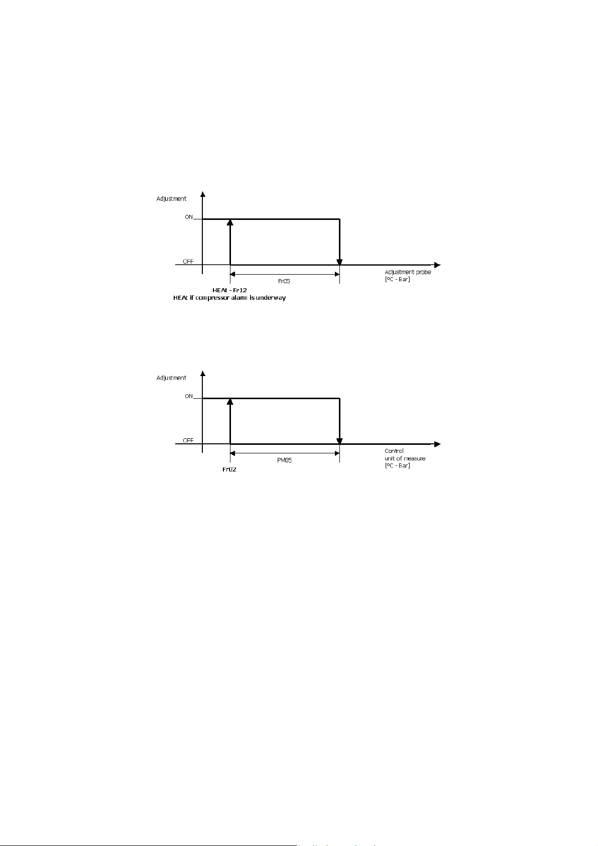
The heating elements come on when the temperature of the adjustment probe falls below threshold set by parameter HEAt - Fr12 for a
time period of Fr11. They switch off when the temperature rises above the threshold set by (HEAt - Fr12) + Fr05. If the compressor is
in alarm mode, the adjustment is made without delay from when the heat set-point is reached.
7.5.3 Heating elements in antifreeze mode
The heating element comes on when the pump is switched on and the minimum temperature between the input and output water is
lower than the parameter Fr02.
page 37 of 52
Page 38
EVCO S.p.A. EV3 HP & EVD HP | Installer manual ver. 1.2 | Code 1443DHPE124
7.6 Condensation control
7.6.1 Initial information
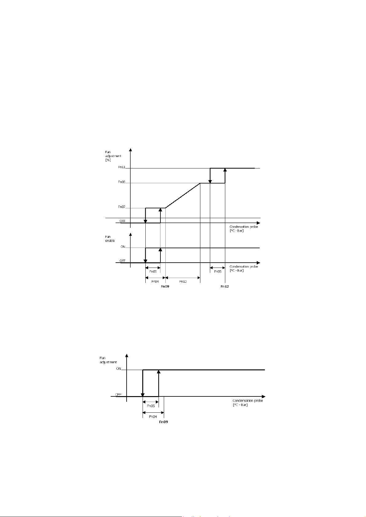
The condensation is controlled by adjustments to the fan that can either be a proportional or O N-OFF type.
If an ON-OFF fan is to be used, connect it to digital output “Enable fan”.
If a proportional adjustment fan is to be used, it should be connected to analogue outlet “Fan”. If an enable outlet is to be used to work
the modulating fan it only has to be connected to digital output “Enable fan”.
For modulating fans, parameter Fn01 enables the start-up time only if the output is configured as cutting phase (CF36 = 1.
The fan can be adjusted independently of the compressor (Fn03=1) or at the request of the compressor (Fn03=0). When the fan is
switched off this will be by-passed by a time equal to Fn06 from switch-on of a compressor. During this period, the fan is set to
minimum speed if the regulator requests cut-off.
7.6.2 Adjustment in cold mode
The diagram below represents the proportional adjustment in cold mode.
In this mode, parameter Fn13 (external fan pre-ventilation time) is also activated to avoid the compressor starting up at a
condensation temperature that is too high. Depending on this parameter, the fan is activated for a time equal to Fn13 before the
compressor is switched on and the fan speed is proportional to the condensation temperature. During this period, the fan is set to
minimum speed if the regulator requests cut-off.
The diagram below represents the ON-OFF adjustment in cold mode.
page 38 of 52
Page 39
EVCO S.p.A. EV3 HP & EVD HP | Installer manual ver. 1.2 | Code 1443DHPE124
7.6.3 Adjustment in hot mode
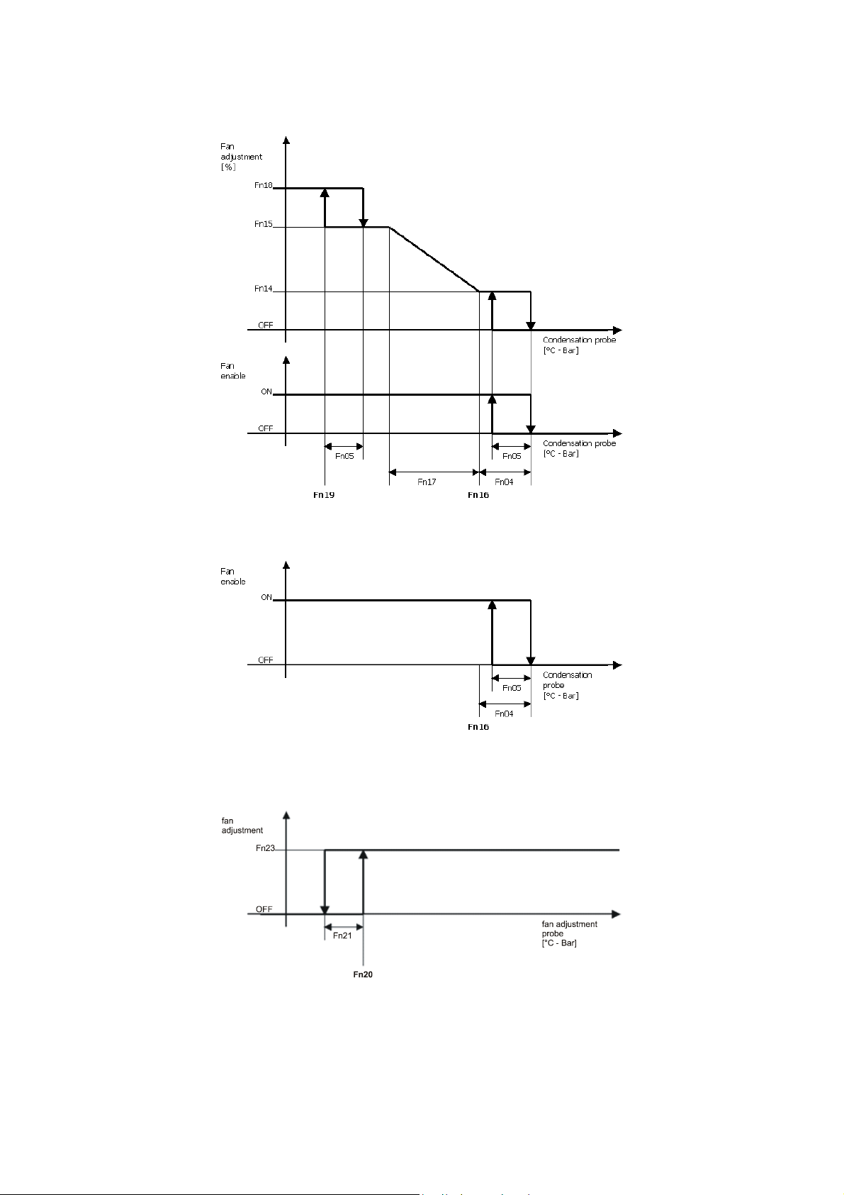
The diagram below represents the proportional adjustment in hot mode.
The diagram below represents the ON-OFF adjustment in hot mode.
7.6.4 Regolazione in sbrinamento
During the start-defrost period, the fan remains off.
The diagram below represents the fan adjustment when a defrost cycle is underway (with compressor in On mode).
During the dripping period, the fan is first switched off and once the 4-ways valve is inverted, it is switched back on at the maximum
speed for a time equal to dF07.
page 39 of 52
Page 40
EVCO S.p.A. EV3 HP & EVD HP | Installer manual ver. 1.2 | Code 1443DHPE124
7.7 Defrost
7.7.1 Initial information
The defrost function is only active if the system is in Heating mode and enabled by parameter dF01.
dF01 = 0 Defrost disabled
dF01 = 1 Defrost with activated compressor
dF01 = 2 Defrost for compressor stop (similar to dF01 = 1 but without activating the compressor)
dF01 = 3 Time interval defrost (similar to dF01 = 1 but ending up for exceeded time)
The battery probe regulates the start and end defrost cycles.
7.7.2 Start defrost control
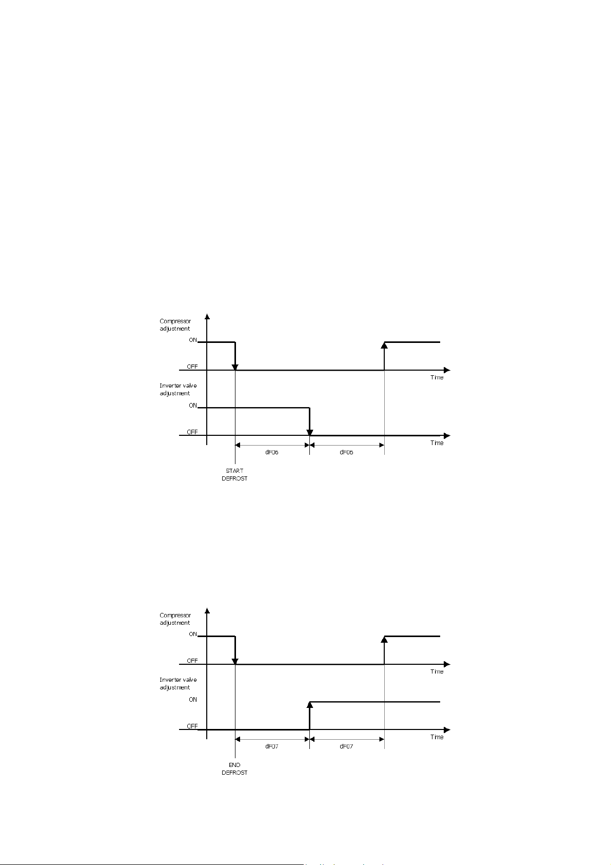
When the reading indicated by the probe is below the dF02 threshold and the compressor is activated, a counter starts up. When the
counter reaches the dF03 value and the dF08 time period has elapsed since the last defrost, a defrost cycle is activated. The counter
stops if the probe reading rises above the dF02 threshold or the compressor is switched off.
The reversing valve is regulated after a delay equal to the time expressed by parameter dF06 and the compressor is switched back on
at full power (df01 = 1 o 3) after a further wait equal to the time expressed by the parameter dF06, also with a switch-on waiting time
of dF09. If the reading rises above Fn20, the fans are activated on full power; if it falls below Fn20-Fn21, the fans stop.
The diagram below shows the start defrost cycle.
7.7.3 End defrost control
Defrost is interrupted when the reading detected by the probe rises above the dF04 threshold (df01 = 1 o 2) or if the duration of the
defrost is equal to Df05 (always valid if df01 = 3)..
Just as for the start defrost control, the reversing valve is regulated after a delay equal to the time expressed by parameter dF07 and
the compressor is switched back on at full power after a further wait equal to the time expressed by parameter dF07.
The diagram below shows the end defrost cycle.
page 40 of 52
Page 41

EVCO S.p.A. EV3 HP & EVD HP | Installer manual ver. 1.2 | Code 1443DHPE124
8 ALARMS
8.1 Initial information
All the alarms re-arm automatically except for:
- Antifreeze alarm: manual re-arm
- Low pressure alarm: manual re-arm if, in an hour, the number of events is higher than parameter AL01
- Flow alarm: manual re-arm if, in an hour, the number of events is higher than parameter AL07
Prolonged pressure of the On/stand-by key resets all manual re-arm alarms.
8.2 List of alarms
The table below shows the meaning of the device’s various alarm codes.
CODE DESCRIPTION
High pressure alarm
The alarm is activated both by the maximum pressure switch and when the value of the condensation probe exceeds the
AHP1
threshold set by AL05. The alarm is deactivated when both conditions return to normal.
Main results
- The compressor is switched off.
ALP1
AtC1
AdS1
AtF1
Low pressure alarm
The alarm is activated both by the minimum pressure switch and when the value of the condensation probe falls below
the threshold set by AL03. The alarm is deactivated when both conditions return to normal.
The alarm is activated after a delay of AL02 from compressor switch-on.
Main results
- The compressor and fan are switched off.
Compressor thermal protection alarm
The alarm is activated if the input configured as a compressor thermal protection input is active. It deactivates if the
input is inactive.
Main results
- The compressor is switched off.
Compressor discharge alarm
The alarm is activated if the value detected by the probe configured as a compressor discharge temperature exceeds
AL17. The alarm is deactivated when the temperature falls below AL17-AL18.
Main results:
- The compressor is switched off.
Fan thermal protection alarm
The alar m is activated if the input configured as fan thermal protection is active. It deactivates if the input is inactive.
Main results
- The compressor and fan are switched off.
AFr1
Antifreeze alarm
The alarm is calculated on the minimum temperature reading of the input and output water probes: the alarm is
activated when the minimum value is below AL12; it is deactivated when the value is above AL12+AL13.
The alarm is delayed for a period equalling AL11 from when it is switched on in hot mode.
Main results
- The compressor and fan are switched off.
page 41 of 52
Page 42

EVCO S.p.A. EV3 HP & EVD HP | Installer manual ver. 1.2 | Code 1443DHPE124
Flow alarm
This alarm is activated when the input configured as a flow switch is active for a period of AL09, with a delay of AL08
AFLo
AHtr
from pump switch-on; it is deactivated when the input is inactive for a time amounting to AL10.
It reverts to manual re-arm if the number of alarm events in an hour exceeds AL07.
Main results
- All functions switched off.
High temperature alarm
This alarm is activated when the input water temperature exceeds AL15 for a period longer than AL16. It is deactivated
when the temperature is lower than AL15-AL13.
Main results
- The compressor is switched off.
EA01
EA02
EA03
EA04
EA05
Probe alarms
The alarm is activated in the following situations:
- when a probe short circuits or is interrupted
- if the upper or lower limits set for a probe are exceeded
Main results
- All functions switched off.
page 42 of 52
Page 43
EVCO S.p.A. EV3 HP & EVD HP | Installer manual ver. 1.2 | Code 1443DHPE124
9 ACCESSORIES
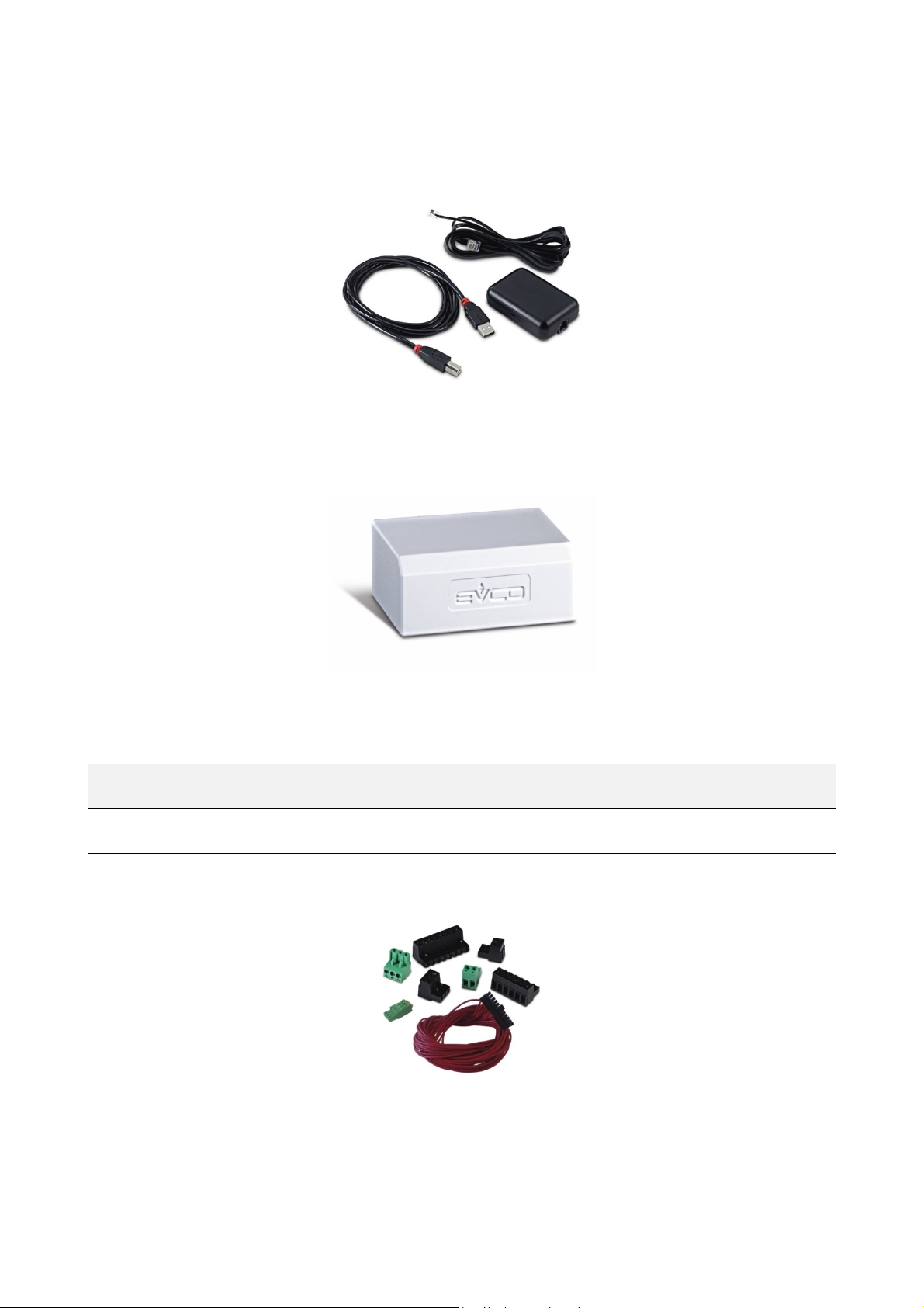
9.1 EVIF20SUXI RS-485/USB serial interface
9.1.1 Initial information
This interface makes it possible to connect EV3 HP and EVD HP to the set-up software Parameters Manager.
9.2 0025100010 drip protector
9.2.1 Initial information
This drip protector shields EV3 HP and EV3K01 fr om damp.
9.3 CJAV connection kit
9.3.1 Initial information
These kits make it possible to cable EV3 HP and EVD HP.
CONTROLLER PURCHASING CODE
EV3 HP CJAV37
EVD HP CJAV38
page 43 of 52
Page 44

EVCO S.p.A. EV3 HP & EVD HP | Installer manual ver. 1.2 | Code 1443DHPE124
10 TECHNICAL SPECIFICATIONS
10.1 Technical specifications
EV3 HP
Purpose of the control
device
Construction of the
control device
Container
Category of heat and fire
resistance
EVD HP
EV3K01
EV3 HP
EVD HP
EV3K01
EV3 HP Black, self-extinguishing.
EVD HP Grey, self-extinguishing.
EV3K01 Black, self-extinguishing.
EV3 HP
EVD HP
Function controller.
Built-in electronic device.
D.
Measurements
Mounting methods for the
control device
Degree of front
protection
EV3K01
EV3 HP 75.0 x 33.0 x 59.0mm (2.952 x 1.299 x 2.322 in; L x H x D).
EVD HP 71.0 x 110.0 x 60.0mm (2.795 x 4.330 x 2.362 in; L x H x D); 4 DIN modules.
EV3K01 75.0 x 33.0 x 39.5mm (2.952 x 1.299 x 1.555 in; L x H x D).
EV3 HP To be fitted to a panel, snap-in brackets provided.
EVD HP
EV3K01 To be fitted to a panel, snap-in brackets provided.
EV3 HP IP65.
EVD HP IP40.
EV3K01 IP65.
On a DIN rail 35.0 x 7.5 mm (1.377 x 0.295 in) or 35.0 x 15.0mm (1.377 x
0.590 in), in a control panel.
page 44 of 52
Page 45
EVCO S.p.A. EV3 HP & EVD HP | Installer manual ver. 1.2 | Code 1443DHPE124
- Micro-Fit connector (power supply, analogue inputs, digital inputs, analogue
outputs and powered INTRABUS communications port)
- Edge connectors (digital outputs)
- Plug-in screw terminal block
- Micro-Fit connector (analogue inputs, digital inputs, analogue outputs and open
collector digital output)
- Plug-in screw terminal blocks (power supply, electro-mechanical relay digital
outputs and communications ports).
(RS-485 MODBUS slave communications port).
Connections:
EV3 HP
EVD HP
EV3K01 Plug-in screw terminal block (power supply and communications port).
The maximum length of the connection cables are as follows:
- power supply:
- for EV3 HP 10m (32.8ft)
- for EVD HP 10m (32.8ft)
- for EV3K01:
- 10m (32.8ft) if the power supply is supplied by EVD HP
- 3m (9.8ft) for independent power supply
- Analogue inputs: 10m (32.8ft)
- Power supply for transducer analogue inputs 4-20mA: 10m (32.8ft)
- Digital inputs: 10m (32.8ft)
- Analogue outputs 0-10V: 10m (32.8ft)
- Phase cutting analogue outputs: 10m (32.8 ft)
- PWM analogue outputs: 1m (3.28ft)
- Electro-mechanical relay digital outputs: 10m (32.8ft)
- Triac digital outputs: 10m (32.8ft)
- Open collector digital outputs: 10m (32.8ft)
- INTRABUS powered ports: 10m (32.8 ft)
- RS-485 MODBUS slave ports: 1,000m (3,280ft); see also the MODBUS manual, specifications
and implementation guides available on http://www.modbus.org/specs.php.
Use cables of an adequate section for the current running through them.
For EV3 HP cabling we recommend using the CJAV37 connection kit (to be ordered separately). For
EVD HP cabling we recommend using the CJAV38 connection kit (to be ordered separately).
Operating temperature
Storage temperature
EV3 HP
From -10 to 55°C (from 14 to 131°F). EVD HP
EV3K01
EV3 HP
From -25 to 70°C (from -13 to 158°F). EVD HP
EV3K01
page 45 of 52
Page 46

EVCO S.p.A. EV3 HP & EVD HP | Installer manual ver. 1.2 | Code 1443DHPE124
EV3 HP
Operating humidity
Pollution status of the
control device
Operating altitude
Transport altitude
EV3K01
EV3 HP
EVD HP
EV3K01
EV3 HP
EV3K01
EV3 HP
Relative humidity without condensate from 10 to 90%. EVD HP
2.
from 0 to 2,000m (from 0 to 6,591ft). EVD HP
From 0 to 3,048m (from 0 to 10,000ft). EVD HP
Environmental
compliance
EMC compliance
Power supply
EV3K01
EV3 HP
EVD HP
EV3K01
EV3 HP
EVD HP
EV3K01
EV3 HP
EVD HP
- RoHS 2011/65/EC
- WEEE 2012/19/EU
- REACH (EC) Regulation 1907/2006.
- EN 60730-1
- IEC 60730-1.
12VAC (±15%), 50/60 Hz (±3 Hz), max. 6VA not insulated, supplied by a class 2
circuit.
Protect the power supply with a 1 A-T 250V fuse.
115... 230VAC (+10% -15%), 50/60 Hz (±3 Hz), max. 6VA insulated.
Protect the power supply with a 2 A-T 250V fuse.
- 12VAC (+10 % -15 %), 50/60 Hz (±3 Hz), max. 7VA not insulated.
EV3K01
- 12VDC (±15%), max. 5W not insulated, supplied by a class 2 circuit.
Protect the power supply with a 1 A-T 250V fuse.
page 46 of 52
Page 47

EVCO S.p.A. EV3 HP & EVD HP | Installer manual ver. 1.2 | Code 1443DHPE124
EV3 HP
Rated impulse-withstand
voltage
Over-voltage category
Software class and
structure
Clock
EVD HP
4 KV.
EV3K01
EV3 HP III.
EVD HP II.
EV3K01 Not applicable.
EV3 HP
EVD HP
A.
EV3K01
EV3 HP
On request (with secondary lithium battery).
Battery autonomy in the absence of a power supply: > 6 months at 25°C (77°F).
Battery charging time: 24h (the battery is charged by the power supply of the
device).
EVD HP
Drift: ≤ 60s/month at 25°C (77°F).
Analogue inputs
EV3K01 Not available.
EV3 HP
5 inputs:
- 4 for NTC probes
- 1 can be set up using the configuration parameter for NTC 4-20mA probes or
EVD HP
transducers
EV3K01 None.
NTC analogue inputs (10 KΩ @ 25 °C, 77 °F)
Sensor type: ß3435.
Measurement field: from -50 to 150°C (from -58 to 248°F).
Resolution: 0.1°C.
Accuracy: 0.5°C from -20 to 40°C, 1°C from -40 to 120°C, 2°C from -50 to 150°C.
Protection: none.
Analogue inputs 4-20 mA
Input resistance: ≤ 200 Ω.
Resolution: 0.02mA.
Protection: none; the maximum current permitted on each input is 25mA.
Digital inputs
EV3 HP
5 volt-free contact inputs.
EVD HP
page 47 of 52
Page 48

EVCO S.p.A. EV3 HP & EVD HP | Installer manual ver. 1.2 | Code 1443DHPE124
EV3K01 None.
Volt-free contact digital inputs (5 VDC, 1,5mA)
Power supply: none.
Protection: none.
Analogue outputs
EV3 HP
2 outputs that can be set up using the configuration parameter for 0-10V, phase
cutting or PWM.
EVD HP
EV3K01 none.
Analogue outputs 0-10V (max. 10mA)
Input resistance: 1 KΩ.
Resolution: 0.01 V.
Protection: none.
Phase cutting analogue outputs
Output: 10VDC, max. 10mA
Protection: none.
PWM analogue outputs
Output: 10VDC, max. 10mA
Frequency: 10... 2KHz.
Duty cycle: 5... 95%.
Protection: none.
Up to 6 outputs:
EV3 HP
- 4 with SPST electro-mechanical relay, 2A res. @ 250 VAC
- 1 with triac 200mA res. @ 250VAC at 25°C (77°F)
- 1 with triac, 2A res. @ 250VAC at 25°C (77°F).
Digital outputs
Up to 5 outputs:
- 2 with SPST electro-mechanical relay, 3A res. @ 250VAC
EVD HP
- 1 with SPST electro-mechanical relay, 8A res. @ 250VAC
- 1 with SPST electro-mechanical relay, 12A res. @ 250VAC
- 1 with open collector, 12VDC, max. 40mA.
EV3K01 None.
EV3 HP
Type 1.
Type 1 or Type 2 Actions
EVD HP
EV3K01 Not applicable.
page 48 of 52
Page 49

EVCO S.p.A. EV3 HP & EVD HP | Installer manual ver. 1.2 | Code 1443DHPE124
EV3 HP
C.
Additional features of
Type 1 or Type 2 actions
EVD HP
EV3K01 not applicable.
EV3 HP Custom 4+4 digit display.
Displays
Communications ports
Alarm buzzer
EVD HP Signalling LED.
EV3K01 Custom 4+4 digit display.
EV3 HP
Up to 2 ports:
- 1 powered INTRABUS port
EVD HP
- 1 RS-485 MODBUS slave port
EV3K01 1 powered INTRABUS port.
EV3 HP Built-in.
EVD HP Not available.
EV3K01 Built-in.
page 49 of 52
Page 50

EVCO S.p.A. EV3 HP & EVD HP | Installer manual ver. 1.2 | Code 1443DHPE124
Notes
_______________________________________________________________________________________
_______________________________________________________________________________________
_______________________________________________________________________________________
_______________________________________________________________________________________
_______________________________________________________________________________________
_______________________________________________________________________________________
_______________________________________________________________________________________
_______________________________________________________________________________________
_______________________________________________________________________________________
_______________________________________________________________________________________
_______________________________________________________________________________________
_______________________________________________________________________________________
_______________________________________________________________________________________
_______________________________________________________________________________________
_______________________________________________________________________________________
_______________________________________________________________________________________
_______________________________________________________________________________________
_______________________________________________________________________________________
_______________________________________________________________________________________
_______________________________________________________________________________________
_______________________________________________________________________________________
_______________________________________________________________________________________
_______________________________________________________________________________________
_______________________________________________________________________________________
_______________________________________________________________________________________
_______________________________________________________________________________________
_______________________________________________________________________________________
_______________________________________________________________________________________
_______________________________________________________________________________________
_______________________________________________________________________________________
_______________________________________________________________________________________
_______________________________________________________________________________________
_______________________________________________________________________________________
_______________________________________________________________________________________
page 50 of 52
Page 51

EVCO S.p.A. EV3 HP & EVD HP | Installer manual ver. 1.2 | Code 1443DHPE124
EV3 HP & EVD HP
Controllers for reversible single-circuit residential heat pumps
Installer manual ver. 1.2
GA - 03/16
Code 1443DHPI124
This document is the sole property of EVCO. EVCO does not accept any liability for any possible errors it includes.
The customer (builder, installer or end-user) assumes all responsibility for the configuration of the device.
EVCO may not be held liable for any damage caused by failure to follow the instructions.
EVCO reserves the right to make any modifications, without prejudicing the essential functional and safety features.
page 51 of 52
Page 52

EVCO S.p.A. EV3 HP & EVD HP | Installer manual ver. 1.2 | Code 1443DHPE124
EVCO S.p.A.
Via Feltre 81, 32036 Sedico Belluno ITALY
Tel. 0437/8422 | Fax 0437/83648
[email protected] | www.e vco.it
page 52 of 52
 Loading...