

Page 1
EVCO S.p.A. | EV3221 & EV3231 | Instruction sheet ver. 1.0 | Code 1043221E103 | Page 1 of 2 | PT 44/16
EV3221 & EV3231
E ENGLISH
- Controllers for normal temperature units.
- Power supply 230 VAC, 115 VAC or 12-24 VAC/DC (according to the model).
- Incorporated clock (according to the model).
- Cabinet probe (PTC/NTC).
- Door switch/multi-purpose input.
- Compressor relay 16 A res. @ 250 VAC or 30 A res. @ 250 VAC (according to the
model).
- Alarm buzzer.
- TTL or RS-485 MODBUS slave port for BMS (according to the model).
- Cooling or heating operation.
1 MEASUREMENTS AND INSTALLATION
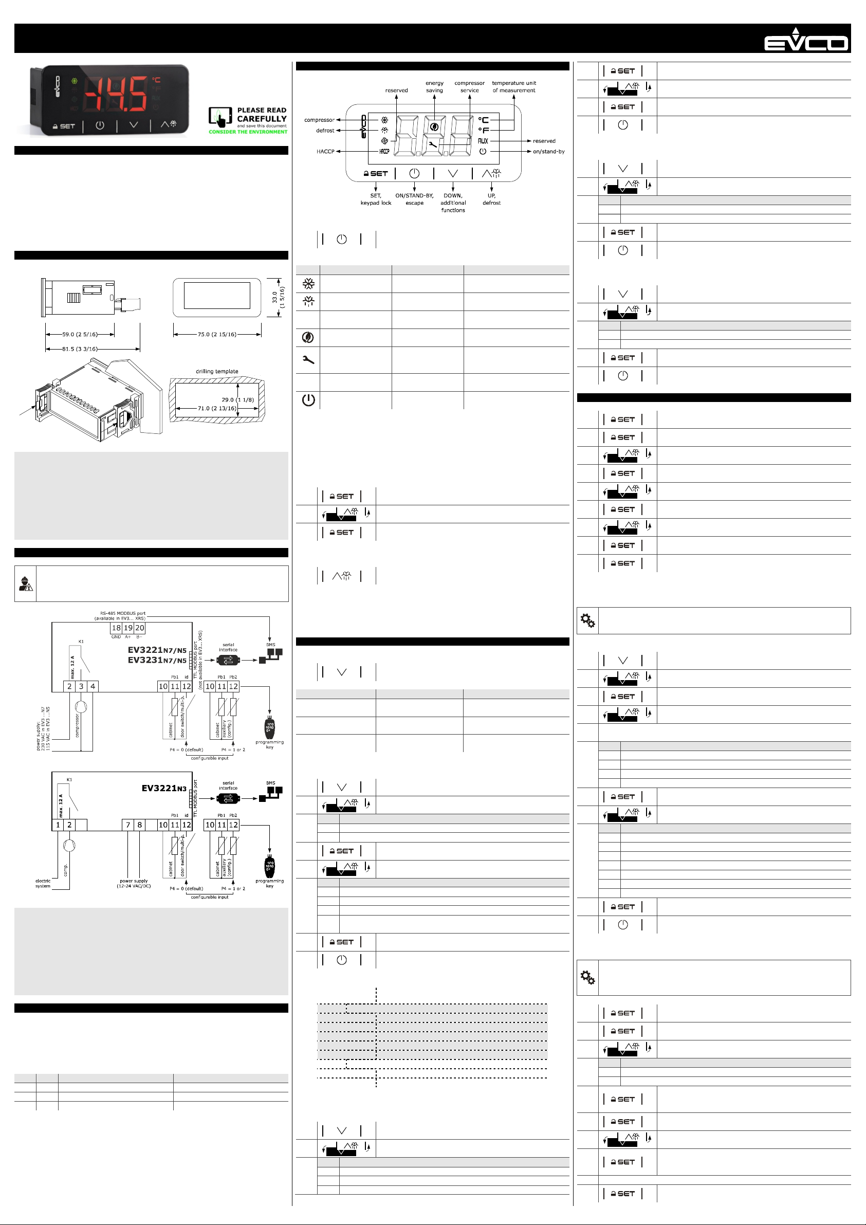
Measurements in mm (inches). To be fitted to a panel, snap-in brackets provided.
INSTALLATION PRECAUTIONS
- The thickness of the panel must be between 0.8 and 2.0 mm (1/32 and 1/16 in)
- Ensure that the working conditions are within the limits stated in the TECHNICAL
SPECIFICATIONS section.
- Do not install the device close to heat sources, equipment with a strong magnetic field,
in places subject to direct sunlight, rain, damp, excessive dust, mechanical vibrations
or shocks.
- In compliance with safety regulations, the device must be installed properly to ensure
adequate protection from contact with electrical parts. All protective parts must be
fixed in such a way as to need the aid of a tool to remove them.
2 ELECTRICAL CONNECTION
N.B.
- Use cables of an adequate section for the current running through them.
- To reduce any electromagnetic interference connect the power cables as far away
as possible from the signal cables.
PRECAUTIONS FOR ELECTRICAL CONNECTION
- If using an electrical or pneumatic screwdriver, adjust the tightening torque.
- If the device has been moved from a cold to a warm place, the humidity may have
caused condensation to form inside. Wait about an hour before switching on the
power.
- Make sure that the supply voltage, electrical frequency and power are within the set
limits. See the section TECHNICAL SPECIFICATIONS.
- Disconnect the power supply before doing any type of maintenance.
- Do not use the device as safety device.
- For repairs and for further information, contact the EVCO sales network.
3 FIRST-TIME
1. Install following the instructions given in the section MEASUREMENTS AND INSTALLATION.
2. Power up the device as shown in the section ELECTRICAL CONNECTION and an internal
test will be run.
The test normally takes a few seconds, when it is finished the display will switch off.
3. Configure the device as shown in the section Setting configuration parameters.
Recommended configuration parameters for first-time use.
PAR. DEF. PARAMETER MIN... MAX.
SP 0.0 setpoint r1... r2
P0 1 probe type 0 = PTC 1 = NTC
P2 0 temperature unit of measurement 0 = °C 1 = °F
Then check that the remaining settings are appropriate; see the section CONFIGURA-
TION PARAMETERS.
4. Disconnect the device from the mains.
5. Make the electrical connection as shown in the section ELECTRICAL CONNECTION without powering up the device.
6. For the connection in an RS-485 network connect the interface EVIF22TSX or
EVIF23TSX, to activate real time functions connect the module EVIF23TSX (or use
EV3... XRS); see the relevant instruction sheets.
7. Power up the device.
Controllers for refrigerated cabinets, undercounters and islands,
with energy-saving strategies
4 USER INTERFACE AND MAIN FUNCTIONS
4.1 Switching the device on/off
1.
If the device is switched on, the display will show the P5 value ("cabinet temperature" default);
if the display shows an alarm code, see the section ALARMS.
LED ON OFF FLASHING
compressor on
defrost active
saved HACCP alarm -
HACCP
energy saving active -
request for compressor service
view temperature -
°C/°F
device off
If 30 s have elapsed without the keys being pressed, the display will show the “Loc” label and
the keypad will lock automatically.
4.2 Unlock keypad
Touch a key for 1 s: the display will show the label “UnL”.
4.3 Set the setpoint
Check that the keypad is not locked.
1.
2.
3.
4.4 Activate manual defrost (if r5 = 0, default)
Check that the keypad is not locked and that overcooling is not active.
1.
If P4 = 1, defrost is activated provided that the evaporator temperature is lower than the d2
threshold.
4.5 Silence buzzer (if A13 = 1)
Touch a key.
5 ADDITIONAL FUNCTIONS
5.1 Activate/deactivate overcooling, overheating and manual energy saving
Check that the keypad is not locked.
1.
FUNCTION CONDITION CONSEQUENCE
overcooling
overheating
energy saving
5.2 View/delete HACCP alarm information
Check that the keypad is not locked.
1.
2.
LAB. DESCRIPTION
LS view HACCP alarm information
rLS delete HACCP alarm information
3.
4.
COD. DESCRIPTION
AL low temperature alarm
AH high temperature alarm
id door switch alarm
PF power failure alarm (available in EV3... XRS or if module EVIF23TSX is con-
5.
6.
Example of alarm information (e.g. a high temperature alarm).
Sta (available in EV3... XRS or if module EVIF23TSX is connected)
y15 alarm signalled in 2015
n03 alarm signalled in March
d26 alarm signalled on 26 March 2015
h16 alarm signalled at 16:00
n30 alarm signalled at 16:30
dur
h01 alarm lasted 1h
n15 alarm lasted 1h 15 min
5.3 View/delete compressor functioning hours and view compressor start-up
Check that the keypad is not locked.
1.
2.
LAB. DESCRIPTION
CH view compressor functioning hours (hundreds)
rCH delete compressor functioning hours
nS1 compressor start-up number (thousands)
nected)
8.0
number
If POF = 1, touch the ON/STAND-BY key for 4 s.
compressor off
-
-
device on
Touch the SET key.
Touch the UP or DOWN key within 15 s to set the value within
the limits r1 and r2 (default “-50... 50”)
Touch the SET key (or do not operate for 15 s).
Touch the UP key for 2 s.
Touch the DOWN key.
r5 = 0, r8 = 1 and defrost
not active
r5 and r8 = 1
r5 = 0 and r8 = 2
Touch the DOWN key for 4 s.
Touch the UP or DOWN key within 15 s to select a label.
Touch the SET key.
Touch the UP or DOWN key to select an alarm code (when label
“LS” is selected) or to set “149” (when label “rLS” is selected).
Touch the SET key.
Touch the ON/STAND-BY key (or do not operate for 60 s) to exit
the procedure.
critical value (cabinet/ calculated product temperature)
was 8.0 °C/°F
Touch the DOWN key for 4 s.
Touch the UP or DOWN key within 15 s to select a label.
- compressor protection active
- setpoint setting active
dripping active
new HACCP alarm saved
-
- settings active
- access to additional functions
active
overcooling or overheating active
device on/off active
the setpoint becomes “setpoint r6”, for the r7 duration
the setpoint becomes “setpoint +
r6”, for the r7 duration
the setpoint becomes “setpoint +
r4”, at maximum for HE2 duration
3.
4.
5.
6.
5.4 View the temperature detected by the probes
Check that the keypad is not locked.
1.
2.
LAB. DESCRIPTION
Pb1 cabinet temperature
Pb2 auxiliary temperature (if P4 = 1 or 2)
3.
4.
5.5 View the project number and the firmware revision
Check that the keypad is not locked.
1.
2.
LAB. DESCRIPTION
PrJ view the project number
rEU view the firmware revison
3.
4.
6 SETTINGS
6.1 Setting configuration parameters
1.
2.
3.
4.
5.
6.
7.
8.
9.
6.2 Set the date, time and day of the week (available in EV3... XRS or if module
EVIF23TSX is connected)
N.B.
Do not disconnect the device from the mains within two minutes since the setting of
the time and day of the week.
Check that the keypad is not locked.
1.
2.
3.
4.
5. Repeat actions 3. and 4. to set the next labels.
LAB. DESCRIPTION OF THE NUMBERS FOLLOWING THE LABEL
n month (01… 12)
d day (01… 31)
h time (00… 23)
n minute (00… 59)
6.
7.
LAB. DESCRIPTION
Mon Monday
tuE Tuesday
UEd Wednesday
thu Thursday
Fri Friday
Sat Saturday
Sun Sunday
8.
9.
6.3 Restore the factory settings (default) and store customized settings as default
N.B.
- Check that the factory settings are appropriate; see the section CONFIGURATION
PARAMETERS.
- the storing of customized settings overwrites the default.
1.
2.
3.
VAL. DESCRIPTION
149 value to restore the factory settings (default)
161 value to store customized settings as default
4.
5.
6.
7.
8. Interrupt the power supply to the device.
9.
Touch the SET key.
Touch the UP or DOWN key to set “149” (when label “rCH” is se-
lected).
Touch the SET key.
Touch the ON/STAND-BY key (or do not operate for 60 s) to exit
the procedure.
Touch the DOWN key for 4 s.
Touch the UP or DOWN key within 15 s to select a label.
Touch the SET key.
Touch the ON/STAND-BY key (or do not operate for 60 s) to exit
the procedure.
Touch the DOWN key for 4 s.
Touch the UP or DOWN key within 15 s to select a label.
Touch the SET key.
Touch the ON/STAND-BY key (or do not operate for 60 s) to exit
the procedure.
Touch the SET key for 4 s: the display will show the label “PA”.
Touch the SET key.
Touch the UP or DOWN key within 15 s to set the PAS value (de-
fault “-19”).
Touch the SET key (or do not operate for 15 s): the display will
show the label “SP”.
Touch the UP or DOWN key to select a parameter.
Touch the SET key.
Touch the UP or DOWN key within 15 s to set the value.
Touch the SET key (or do not operate for 15 s).
Touch the SET key for 4 s (or do not operate for 60 s) to exit the
procedure.
Touch the DOWN key for 4 s.
Touch the UP or DOWN key within 15 s to select the label “rtc”.
Touch the SET key: the display will show the label “yy” followed
by the last two figures of the year.
Touch the UP or DOWN key within 15 s to set the year.
Touch the SET key: the display will show the label for the day of
the week.
Touch the UP or DOWN key within 15 s to set the day of the
week.
Touch the SET key: the device will exit the procedure.
Touch the ON/STAND-BY key to exit the procedure beforehand.
Touch the SET key for 4 s: the display will show the label “PA”.
Touch the SET key.
Touch the UP or DOWN key within 15 s to set the value.
Touch the SET key (or do not operate for 15 s): the display will
show the label “dEF” (when value “149” is set) or the label
“MAP” (when value “161” is set).
Touch the SET key.
Touch the UP or DOWN key within 15 s to set “4”.
Touch the SET key (or do not operate for 15 s): the display will
show for 4 s “- - -“ flashing, then the device will exit the procedure.
Touch the SET key 2 s before action 6. to exit the procedure beforehand.
Page 2
EVCO S.p.A. | EV3221 & EV3231 | Instruction sheet ver. 1.0 | Code 1043221E103 | Page 2 of 2 | PT 44/16
31
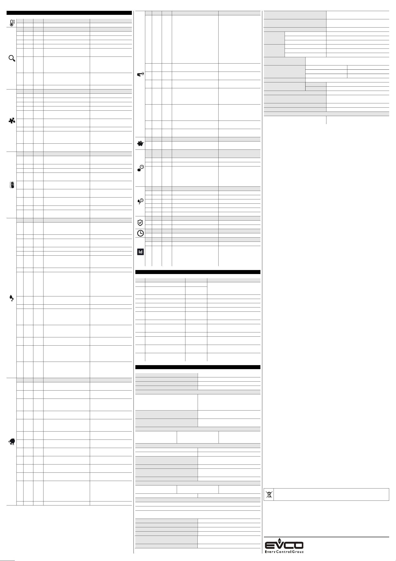
7 CONFIGURATION PARAMETERS
N. PAR. DEF. SETPOINT MIN... MAX.
1 SP 0.0 setpoint r1... r2
N. PAR. DEF. ANALOGUE INPUTS MIN... MAX.
2 CA1 0.0 cabinet probe offset -25... 25 °C/°F
3 CA2 0.0 auxiliary probe offset -25... 25 °C/°F
4 P0 1 probe type 0 = PTC 1 = NTC
5 P1 1 enable °C decimal point 0 = no 1 = yes
6 P2 0 temperature unit of measure-
7
P4
8
P5
9 P8 5 display refresh time 0... 250 s : 10
N. PAR. DEF. REGULATION MIN... MAX.
10 r0 2.0 setpoint differential 1... 15 °C/°F
11 r1 -50 minimum setpoint -99 °C/°F... r2
12 r2 50.0 maximum setpoint r1... 199 °C/°F
13 r4 0.0 setpoint offset in energy saving 0... 99 °C/°F
14
r5 0 cooling or heating operation 0 = cooling
15
r6 0.0 setpoint offset in overcool-
16 r7 30 overcooling/overheating duration 0... 240 min
17
r8
18
r12 0 position of the r0 differential 0 = asymmetric
N. PAR. DEF. COMPRESSOR MIN... MAX.
19
C0 0 compressor on delay after pow-
20 C2 3 compressor off minimum time 0... 240 min
21 C3 0 compressor on minimum time 0... 240 s
22
C4 10 compressor off time during cabi-
23
C5 10 compressor on time during cabi-
24
C6 80.0 threshold for high condensation
25
C7 90.0 threshold for high condensation
26 C8 1 high condensation alarm delay 0... 15 min
27
C10 0 compressor hours for service 0... 999 h x 100
N. PAR. DEF. DEFROST (if r5 = 0) MIN... MAX.
28
d0
29 d2 8.0 threshold for defrost end -99... 99 °C/°F
30
d3 30 defrost duration
d4 0 enable defrost at power-on 0 = no 1 = yes
32 d5 0 defrost dealy after power-on 0... 99 min
33
d6
34 d7 0 dripping time 0... 15 min
35
d8
36
d9 0.0 evaporation threshold for auto-
37 d11 0 enable defrost timeout alarm 0 = no 1 = yes
38
d18
39
d19
40
d20 180 compressor on consecutive time
41
d21
42
d22
N. PAR. DEF. ALARMS MIN... MAX.
43
AA 0 select value for high/low temper-
44
A1 -10.0
45
A2
46
A4 10.0 threshold for high temperature
47
A5
48
A6 12 high temperature alarm delay af-
49
A7 15 high/low temperature alarms de-
50
A8 15 high temperature alarm delay af-
51
A9 15 high temperature alarm delay af-
52
A10 10 power failure duration for alarm
53
A11 2.0 high/low temperature alarms re-
54
A12
55 A13 0 enable alarm buzzer 0 = no 1 = yes
ment
0
configurable input function
0
value displayed
ing/overheating
0
DOWN key additional function
er-on
net probe alarm
net probe alarm
warning
alarm
8
automatic defrost interval
2
value displayed during defrost
0
defrost interval counting mode
matic defrost interval counting
40
adaptive defrost interval
3.0
threshold for adaptive defrost
(relative to optimal evaporation
temperature)
for defrost
200
compressor on consecutive time
for defrost after power-on and
overcooling
-2.0
evaporation threshold for adaptive defrost interval counting
(relative to optimal evaporation
temperature)
ature alarms
threshold for low temperature
alarm
1
low temperature alarm type
alarm
1
high temperature alarm type
ter power-on
lay
ter defrost
ter door closing
recording
set differential
2
power failure alarm notification
type
0 = °C 1 = °F
0 = door switch/multi-pur-
pose input
1 = evaporator probe
2 = condenser probe
0 = cabinet temperature
1 = setpoint
2 = auxiliary temperature
1 = heating
0... 99 °C/°F
0 = disabled
1 = overcooling/overheating
2 = energy saving
1 = symmetric
0... 240 min
0... 240 min
0... 240 min
0... 199 °C/°F
differential = 2 °C/4 °F
0... 199 °C/°F
0 = disabled
0... 99 h
0 = only manual
if d8 = 3, maximum interval
0... 99 min
se P4 = 1, maximum duration
0 = cabinet temperature
1 = display locked
2 = dEF label
0 = device on hours
1 = compressor on hours
2 = hours evaporator tem-
perature < d9
3 = adaptive
4 = real time
-99... 99 °C/°F
0... 999 min
if compressor on + evaporator temperature < d22
0 = only manual
0... 40 °C/°F
optimal evaporation temperature - d19
0... 999 min
0 = disabled
0... 500 min
if (cabinet temperature setpoint) > 10°C/20 °F
0 = disabled
-10... 10 °C/°F
optimal evaporation temperature + d22
0 = cabinet temperature
1 = auxiliary temperature
-99... 99 °C/°F
0 = disabled
1 = relative to setpoint
2 = absolute
-99... 99 °C/°F
0 = disabled
1 = relative to setpoint
2 = absolute
0... 99 min x 10
0... 240 min
0... 240 min
0... 240 min
0... 240 min
1... 15 °C/°F
0 = HACCP LED
1 = HACCP LED + PF label +
buzzer
2 =
HACCP LED + PF label +
buzzer (if duration > A10)
N. PAR. DEF. DIGITAL INPUTS MIN... MAX.
56
i0
1
57
i1 0 door switch/multi-purpose input
58
i2 30 open door alarm delay
59
i3 15 regulation inhibition maximum
60
i7
61
i10
62
i13 180 number of door openings for de-
63
i14 32 door open consecutive time for
N. PAR. DEF. ENERGY SAVING (if r5 = 0) MIN... MAX.
64
HE2 0 energy saving maximum duration
N. PAR. DEF. REAL TIME ENERGY SAVING (if
65 H01 0 energy saving time 0... 23 h
66 H02 0 energy saving duration 0... 24 h
67
HEd
N. PAR. DEF. REAL TIME DEFROST (if d8 = 4) MIN... MAX.
68 Hd1 h- 1st daily defrost time h- = disabled
69 Hd2 h- 2nd daily defrost time h- = disabled
70 Hd3 h- 3rd daily defrost time h- = disabled
71 Hd4 h- 4th daily defrost time h- = disabled
72 Hd5 h- 5th daily defrost time h- = disabled
73 Hd6 h- 6th daily defrost time h- = disabled
N. PAR. DEF. SAFETIES MIN... MAX.
74 POF 0 enable ON/STAND-BY key 0 = no 1 = yes
75 PAS -19 password -99... 999
N. PAR. DEF. REAL TIME CLOCK MIN... MAX.
76 Hr0 0 enable clock 0 = no 1 = yes
N. PAR. DEF. MODBUS MIN... MAX.
77 LA 247 MODBUS address 1... 247
78
Lb
8 ALARMS
COD. DESCRIPTION RESET REMEDIES
Pr1 cabinet probe alarm automatic - check P0
Pr2 auxiliary probe alarm automatic - check probe integrity
- check electrical connection
rtc clock alarm manual set date, time and day of the week
AL low temperature alarm automatic check AA, A1 and A2
AH high temperature alarm automatic check AA, A4 and A5
id open door alarm automatic check i0 e i1
PF power failure alarm
COH high condensation warning automatic check C6
CSd high condensation alarm manual
iA multi-purpose input alarm automatic check i0 and i1
Cth compressor thermal switch
th global thermal switch alarm manual
dFd defrost timeout alarm
9 TECHNICAL SPECIFICATIONS
Purpose of the control device
Construction of the control device
Container Black, self-extinguishing
Category of heat and fire resistance D
Measurements
75.0 x 33.0 x 59.0 mm (2 15/16 x 1 5/16 x
2 5/16 in) with fixed screw terminal blocks;
75.0 x 33.0 x 73.0 mm (2 15/16 x 1 5/16 x
2 7/8 in) in EV3... XRS
Mounting methods for the control device To be fitted to a panel, snap-in brackets pro-
Degree of protection provided by the covering
Connection method
Fixed screw terminal blocks
for wires up to 2,5 mm²
Maximum permitted length for connection cables
Power supply: 10 m (32.8 ft) Analogue inputs: 10 m (32.8 ft)
Digital inputs: 10 m (32.8 ft) Digital outputs: 10 m (32.8 ft)
Operating temperature
Storage temperature
Operating humidity
Pollution status of the control device 2
Conformity
RoHS 2011/65/CE
EMC 2014/30/UE LVD 2014/35/UE
Power supply
230 VAC (+10% -15%), 50/60 Hz (±3 Hz), max. 2 VA insulated in EV3... N7
115 VAC (+10% -15%), 50/60 Hz (±3 Hz), max. 2 VA insulated in EV3... N5
12-24 VAC/DC (+10% -15%), 50/60 Hz (±3 Hz), max. 4 VA/2W in EV3... N3, provided by a
SELV class 2 source
Earthing methods for the control device None
Rated impulse-withstand voltage
Over-voltage category
Software class and structure
Clock
Clock drift
alarm
door switch/multi-purpose input
function
activation
time with door open
0
multi-purpose input alarm delay
0
door closed consecutive time for
energy saving
frost
defrost
r5 = 0)
7
energy saving day
2
MODBUS baud rate
manual
automatic check i0 and i1
manual
Function controller
Built-in electronic device
75.0 x 33.0 x 81.5 mm (2 15/16 x 1 5/16 x
3 3/16 in) with removable screw terminal
blocks; 75.0 x 33.0 x 83.0 mm (2 15/16 x 1
5/16 x 3 1/4 in) in EV3... XRS
vided
IP65 (front)
Removable screw terminal
blocks for wires up to
2,5 mm²; by request
From 0 to 55 °C (from 32 to 131 °F); from 0
to 50 °C (from 32 a 122 °F) in EV3... N3
From -25 to 70 °C (from -13 to 158 °F)
Relative humidity without condensate from
10 to 90%
WEEE 2012/19/EU
4 KV
III; II in EV3... N3
A
Incorporated secondary lithium battery
(available in EV3... XRS)
≤ 60 s/month at 25 °C (77 °F)
0 = none
1 = compressor off
2 = reserved
3 = reserved
4 = reserved
5 = reserved
6 = reserved
7 = energy saving
8 = iA alarm
9 = device on/off
10 = Cth alarm
11 = th alarm
0 = with contact closed
1 = with contact open
-1... 120 min
-1 = disabled
-1... 120 min
-1 = until the closing
-1... 120 min
-1 = disabled
if i0 = 10 or 11, compressor
on delay after alarm reset
0... 999 min
after regulation temperature
< SP
0 = disabled
0... 240
0 = disabled
0... 240 min
0 = disabled
0... 999 min
-1 = until the door opening
MIN... MAX.
0 = Monday 1 = Tuesday
2 = Wednesday
3 = Thursday 4 = Friday
5 = Saturday 6 = Sunday
7 = none
0 = 2,400 baud
1 = 4,800 baud
2 = 9,600 baud
3 = 19,200 baud
parity even
- touch a key
- check electrical connection
- switch the device off and on
- check C7
- switch the device off and on
- check i0 and i1
- touch a key
- check d2, d3 and d11
Micro-MaTch connector
REACH (EC) Regulation
1907/2006
Clock battery autonomy in the absence of a
power supply
Clock battery charging time
Analogue inputs 1 for PTC or NTC probes (cabinet probe)
PTC probes Sensor type
Measurement field
Resolution
NTC probes Sensor type
Measurement field
Resolution
Other inputs
Dry contact Contact type 5 VDC, 1.5 mA
Power supply None
Protection None
Digital outputs 1 electro-mechanical relay (compressor relay)
Compressor relay (K1) EV3221 SPST, 16 A res. @ 250 VAC
EV3231 SPST, 30 A res. @ 250 VAC
Type 1 or Type 2 Actions Type 1
Additional features of Type 1 or Type 2 actions
Displays
Alarm buzzer Incorporated
Communication ports
1 TTL MODBUS slave port for BMS (not available in EV3... XRS)
N.B.
The device must be disposed of according to local regulations governing the collection
of electrical and electronic waste.
This document and the solutions contained therein are the intellectual property of EVCO and thus protected by the Italian Intellectual Property Rights Code (CPI). EVCO imposes an absolute ban on the full
or partial reproduction and disclosure of the content other than with the express approval of EVCO. The
customer (manufacturer, installer or end-user) assumes all responsibility for the configuration of the device. EVCO accepts no liability for any possible errors in this document and reserves the right to make
any changes, at any time without prejudice to the essential functional and safety features of the equipment.
Input configurable for analogue input (auxiliary probe) or
digital input (door switch/multi-purpose, dry contact)
EVCO S.p.A.
Via Feltre 81, 32036 Sedico (BL) ITALY
> 24 h at 25 °C (77 °F)
24 h (the battery is charged by the power
supply of the device)
KTY 81-121 (990 @ 25 °C, 77 °F)
From -50 to 150 °C (from -58 to 302 °F)
0.1 °C (1 °F)
ß3435 (10 K @ 25 °C, 77 °F)
From -40 to 105 °C (from -40 to 221 °F)
0.1 °C (1 °F)
C
3 digits custom display, with function icons
1 RS-485 MODBUS slave port for BMS (available in EV3... XRS)
 Loading...