

Page 1

PROGRAMMABLE CONTROLLERS
FOR SINGLE OR TWIN-CIRCUIT
CHILLERS - HEAT PUMPS
WITH UP TO 6 COMPRESSORS
APPLICATION MANUAL
CODE 144CHILNUE03
Page 2

C-PRO NANO CHIL AND C-PRO MICRO CHIL – APPLICATION MANUAL
Important Notice
This Instruction Manual should be read carefully before installation and before use, and all warnings relating to
installation and electrical connections should be observed; the Manual should then be kept for future reference.
All devices must be disposed of in accordance with local regulations governing the disposal of electrical and
electronic devices.
Pag. 2
Page 3

C-PRO NANO CHIL AND C-PRO MICRO CHIL – APPLICATION MANUAL
Table of Contents
1 General Information..................................................................................................................................................6
1.1 Description ......................................................................................................................................................6
2 Applications ..............................................................................................................................................................8
2.1 Air-to-air single-circuit chiller units and air-to-air single-circuit chiller units + heat pump..........................10
2.1.1 Air-to-air single-circuit chiller units ....................................................................................................10
2.1.2 Air-to-air single-circuit chiller units + heat pump................................................................................12
2.2 Air-to-water single-circuit chiller units and air-to-water single-circuit chiller units + heat pump ................14
2.2.1 Air-to-water single-circuit chiller units................................................................................................14
2.2.2 Air-to-water single-circuit chiller units + heat pump...........................................................................16
2.3 Water-to-water single-circuit chiller units and water-to-water single-circuit chiller units + heat pump .......18
2.3.1 Water-to-water single-circuit chiller units ...........................................................................................18
2.3.2 Water-to-water single-circuit chiller units + heat pump....................................................................... 20
2.4 Single-circuit motocondensing air-based units and single-circuit motocondensing air-based units with cycle
inversion.......................................................................................................................................................................22
2.4.1 Single-circuit motocondensing air-based units ....................................................................................22
2.4.2 Single-circuit motocondensing air-based units with cycle inversion ...................................................24
2.5 Single-circuit motocondensing water-based units and single-circuit motocondensing water-based units with
cycle inversion .............................................................................................................................................................26
2.5.1 Single-circuit motocondensing water-based units................................................................................ 26
2.5.2 Single-circuit motocondensing water-based units with cycle inversion...............................................28
2.6 Air-to-air twin-circuit chiller units and air-to-air twin-circuit chiller units + heat pump ..............................30
2.6.1 Air-to-air twin-circuit chiller units.......................................................................................................30
2.6.2 Air-to-air twin-circuit chiller units + heat pump..................................................................................32
2.7 Air-to-water twin-circuit chiller units and air-to-water twin-circuit chiller units + heat pump .....................34
2.7.1 Air-to-water twin-circuit chiller units .................................................................................................. 34
2.7.2 Air-to-water twin-circuit chiller units + heat pump .............................................................................36
2.8 Water-to-water twin-circuit chiller units and water-to-water twin-circuit chiller units + heat pump ............ 38
2.8.1 Water-to-water twin-circuit chiller units..............................................................................................38
2.8.2 Water-to-water twin-circuit chiller units + heat pump.........................................................................40
2.9 Twin-circuit motocondensing air-based units and twin-circuit motocondensing air-based units with cycle
inversion.......................................................................................................................................................................42
2.9.1 Twin-circuit motocondensing air-based units......................................................................................42
2.9.2 Twin-circuit motocondensing air-based units with cycle inversion.....................................................44
2.10 Twin-circuit motocondensing water-based units and twin-circuit motocondensing water-based units with
cycle inversion .............................................................................................................................................................46
2.10.1 Twin-circuit motocondensing water-based units..................................................................................46
2.10.2 Twin-circuit motocondensing water-based units with cycle inversion ................................................48
2.11 Connection Layout of C-PRO MICRO CHIL and C-PRO EXP MICRO .....................................................50
2.11.1 Connection layout of C-PRO NANO CHIL and C-PRO MICRO CHIL.............................................50
2.11.2 Connection layout of C-PRO EXP MICRO.........................................................................................53
3 Component Network and Accessories ....................................................................................................................55
3.1 Example of C-PRO NANO CHIL .................................................................................................................55
3.2 Example of C-PRO MICRO CHIL (built-in version)....................................................................................56
3.3 Example of C-PRO MICRO CHIL (blind version) .......................................................................................57
4 USER INTERFACE................................................................................................................................................58
4.1 Displays and Keyboards ................................................................................................................................58
4.2 List of Pages ..................................................................................................................................................62
5 Parameter List .........................................................................................................................................................68
5.1 List of Configuration Parameters...................................................................................................................69
6 REGULATIONS..................................................................................................................................................... 82
6.1 Machine Status ..............................................................................................................................................82
6.2 Unit Type....................................................................................................................................................... 83
6.2.1 Single-circuit air-to-air units ................................................................................................................83
6.2.2 Single-circuit air-to-water units ...........................................................................................................84
6.2.3 Single-circuit water-to-water units.......................................................................................................85
6.2.4 Single-circuit motocondensing air-based units ....................................................................................86
Pag. 3
Page 4

C-PRO NANO CHIL AND C-PRO MICRO CHIL – APPLICATION MANUAL
6.2.5 Single-circuit motocondensing water-based units................................................................................ 87
6.2.6 Twin-circuit air-to-air units.................................................................................................................. 88
6.2.7 Twin-circuit air-to-water units ............................................................................................................. 90
6.2.8 Twin-circuit water-to-water units......................................................................................................... 92
6.2.9 Twin-circuit motocondensing air-based units......................................................................................94
6.2.10 Twin-circuit motocondensing water-based units..................................................................................96
6.3 Configuration of Circuits...............................................................................................................................98
6.4 Operating Mode Control................................................................................................................................99
6.4.1 Heat-pump-only mode ....................................................................................................................... 100
6.4.2 Geothermal heat pumps......................................................................................................................100
6.5 Compressor Regulation ...............................................................................................................................101
6.5.1 Lateral-band (LB) regulation ............................................................................................................101
6.5.2 Neutral-zone (NZ) regulation.............................................................................................................102
6.5.3 Compressor activation from digital input...........................................................................................103
6.6 Compressor Management ............................................................................................................................104
6.6.1 Compressor statuses...........................................................................................................................104
6.6.2 Rotation of compressors.....................................................................................................................104
6.6.3 Pump-down switch-OFF procedure ...................................................................................................105
6.6.4 Relative-threshold pump-down.......................................................................................................... 105
6.6.5 Protection timings ..............................................................................................................................106
6.6.6 Thermal protection inputs .................................................................................................................. 107
6.7 Condensation Regulation.............................................................................................................................108
6.7.1 Fan linear regulation .......................................................................................................................... 108
6.7.2 Condensing valve regulation.............................................................................................................. 110
6.7.3 Condensing fan pre-start at high external temperatures.....................................................................110
6.7.4 Single condensation ........................................................................................................................... 110
6.8 Fan Management .........................................................................................................................................111
6.8.1 Fan status ...........................................................................................................................................111
6.8.2 Fan timings......................................................................................................................................... 111
6.8.3 Thermal Protection Inputs.................................................................................................................. 111
6.9 Circulating Pump Management ...................................................................................................................112
6.9.1 Pump Status........................................................................................................................................113
6.10 Internal Fan Management............................................................................................................................113
6.10.1 Hot-start function...............................................................................................................................113
6.10.2 Recirculating fan status...................................................................................................................... 114
6.11 Flow Meter Management.............................................................................................................................114
6.12 Defrosting Management ..............................................................................................................................116
6.12.1 Defrosting management via external contact .....................................................................................117
6.12.2 Defrosting cycle compensation.......................................................................................................... 117
6.12.3 Defrosting heating coil.......................................................................................................................118
6.13 Anti-frost management / Chilling-support heating coils..............................................................................118
6.14 Free-Cooling Management..........................................................................................................................119
6.14.1 Free-Cooling Enable .......................................................................................................................... 119
6.14.2 Free-cooling regulation......................................................................................................................119
6.14.3 Free-cooling control valves................................................................................................................121
6.15 Temperature Alarm Control ........................................................................................................................122
6.15.1 Low and high temperature alarm management ..................................................................................122
6.15.2 Management of primary exchanger efficiency alarm.........................................................................122
6.16 Pressure Alarm Control ...............................................................................................................................123
6.16.1 Management of high-pressure pressure-switch alarm........................................................................123
6.16.2 Management of high-pressure transducer alarm ................................................................................123
6.16.3 Management of low-pressure pressure-switch alarm (chiller mode) .................................................123
6.16.4 Management of low-pressure transducer alarm (heat pump mode) ...................................................123
6.16.5 Low start-up pressure alarm...............................................................................................................124
6.17 Miscellaneous Management ........................................................................................................................125
6.17.1 Set point variation..............................................................................................................................125
6.17.2 External probe configuration (AI04 / AI05).......................................................................................125
6.17.3 Evaporation-probe configuration .......................................................................................................126
6.17.4 Dynamic set point ..............................................................................................................................126
6.17.5 Forced shutdown................................................................................................................................127
6.17.6 Power limiting....................................................................................................................................128
6.17.7 High-pressure partialisation at high temperatures (chiller) ................................................................128
Pag. 4
Page 5

C-PRO NANO CHIL AND C-PRO MICRO CHIL – APPLICATION MANUAL
6.17.8 Low-pressure partialisation at low temperatures (heat pump) ...........................................................129
6.17.9 Operating limit management (heat pump)..........................................................................................131
6.17.10 Function for chilling/heating on demand.......................................................................................131
6.17.11 Manual operation...........................................................................................................................132
6.17.12 Resetting of default parameters..................................................................................................... 133
6.17.13 Programming key .......................................................................................................................... 133
7 DIAGNOSTICS.................................................................................................................................................... 134
7.1 Manual and Automatic Alarms....................................................................................................................134
7.1.1 Manual-reset alarms...........................................................................................................................134
7.1.2 Automatic-reset alarms ......................................................................................................................134
7.2 Alarm Table................................................................................................................................................. 135
7.3 Alarm Relay.................................................................................................................................................136
8 List of Modbus® Variables....................................................................................................................................137
Pag. 5
Page 6

C-PRO NANO CHIL AND C-PRO MICRO CHIL – APPLICATION MANUAL
1 General Information
1.1 Description
C-PRO NANO CHIL and C-PRO MICRO CHIL are two new families of innovative programmable
controllers, which are both flexible and modular, as well as being capable satisfying all application,
technical and cost requirements of modern single and twin-circuit chillers, with capacity from 4 to
450 KW and up to 6 compressors.
The features of the C-PRO NANO and MICRO CHIL controllers – contained size, I/O availability,
price, etc. – enable, for the very first time, the use of programmable devices even in low-complexity
machines such as chillers - heat pumps with a single circuit, capacity from 4 to 80 KW and up to 3
compressors, where until recently it had only been possible to utilise rigid parameter-based
controllers. By connecting to a C-PRO NANO and MICRO CHIL the C-PRO EXP MICRO I/O
expansion, the advantages in control and price offered by the use of these programmable devices
are also extended to twin-circuit units up to 450 KW and 6 compressors.
The display on these products consists of a 4-digit LED display, with function icons, available in
both product families.
The C-PRO NANO and MICRO CHIL controllers feature:
• 9 inputs, three of which are analogue inputs (2 for NTC temperature probes and 1 for
pressure transducers
0-20 / 4-20 mA or for ratiometric transducers, 0-5 V), 5 are digital and 1 is analogue/digital
(i.e. configurable);
• 9 outputs, of which 3 are analogue (one PWM and two 4-20 mA or 0-10 V) and 6 are digital
(electromechanical relays); analogue outputs enable control of inverters for compressors and for
phase-cut speed regulators for fans.
Using the C-PRO EXP MICRO I/O expansion, I/O is doubled.
Thanks to their design and installation features, these controllers are easily installed – the C-PRO
NANO is panel-mounted, while the C-PRO MICRO is DIN-rail-mounted on an electrical board.
Using the EVKEY programming key, it is possible to upload/download parameters; in addition,
these controllers can be connected to RICS monitoring and supervisory systems.
The application software is created with UNI-PRO and is capable of managing air-to-air, air-towater, water-to-water and motocondensing units.
The following are only some of the numerous control functions available:
• free-cooling management
• pump-down management
• dynamic set point compensation
• double set-point that can be enabled from external contact
• possibility of managing up to 3 scroll compressors for each circuit
• possibility of managing compressors with inverter and fans with phase-cut module
• control of condensing pressure / linear or stepped evaporation
• operation as heat pump only
• activation of compressors from motocondensing machine input
• operation as heat pump with low external temperature
• version with one, two or no circulating pumps.
Pag. 6
Page 7

C-PRO NANO CHIL AND C-PRO MICRO CHIL – APPLICATION MANUAL
C-PRO NANO CHIL
C-PRO MICRO CHIL
Built-in version
C-PRO MICRO CHIL
Blind version
C-PRO MICRO CHIL
Open-frame version
Pag. 7
Page 8

C-PRO NANO CHIL AND C-PRO MICRO CHIL – APPLICATION MANUAL
2 Applications
Management of the following unit types is possible:
1) Air-to-air single-circuit chiller units and air-to-air single-circuit chiller units +
heat pump, using C-PRO NANO CHIL (or C-PRO MICRO CHIL).
Total number of analogue inputs: 4.
Total number of digital inputs: 5 (*).
Total number of analogue outputs: 1 + 2 optional.
Total number of digital outputs: 6.
2) Air-to-water single-circuit chiller units and air-to-water single-circuit chiller
units + heat pump, using C-PRO NANO CHIL (or C-PRO MICRO CHIL).
Total number of analogue inputs: 4.
Total number of digital inputs: 5 (*).
Total number of analogue outputs: 1 + 2 optional.
Total number of digital outputs: 6.
3) Water-to-water single-circuit chiller units and water-to-water single-circuit
chiller units + heat pump, using C-PRO NANO CHIL (or C-PRO MICRO CHIL).
Total number of analogue inputs: 4.
Total number of digital inputs: 5 (*).
Total number of analogue outputs: 1 + 2 optional.
Total number of digital outputs: 6.
4) Single-circuit motocondensing air-based units and single-circuit
motocondensing air-based units with cycle inversion, using C-PRO NANO CHIL (or C-PRO
MICRO CHIL).
Total number of analogue inputs: 4.
Total number of digital inputs: 5 (*).
Total number of analogue outputs: 1 + 2 optional.
Total number of digital outputs: 6.
5) Single-circuit motocondensing water-based units and single-circuit
motocondensing water-based units with cycle inversion, using C-PRO NANO CHIL (or C-PRO
MICRO CHIL).
Total number of analogue inputs: 4.
Total number of digital inputs: 5.
Total number of analogue outputs: 1 + 2 optional.
Total number of digital outputs: 6.
(*) Note: The total number of digital inputs is 6, if analogue input AI04 is used as additional digital
input (parameter PH44).
6) Air-to-air single-circuit chiller units and air-to-air single-circuit chiller units +
heat pump, using C-PRO NANO CHIL (or C-PRO MICRO CHIL) and C-PRO EXP
MICRO.
Total number of analogue inputs: 8.
Total number of digital inputs: 10 (*).
Total number of analogue outputs: 2 + 2 optional.
Total number of digital outputs: 12.
Pag. 8
Page 9

C-PRO NANO CHIL AND C-PRO MICRO CHIL – APPLICATION MANUAL
7) Air-to-water twin-circuit chiller units and air-to-water twin-circuit chiller units
+ heat pump, using C-PRO NANO CHIL (or C-PRO MICRO CHIL) and C-PRO EXP MICRO.
Total number of analogue inputs: 8.
Total number of digital inputs: 10 (*).
Total number of analogue outputs: 2 + 2 optional.
Total number of digital outputs: 12.
8) Water-to-water twin-circuit chiller units and water-to-water twin-circuit chiller
units + heat pump, using C-PRO NANO CHIL (or C-PRO MICRO CHIL) and C-PRO EXP
MICRO.
Total number of analogue inputs: 8.
Total number of digital inputs: 10 (*).
Total number of analogue outputs: 2 + 2 optional.
Total number of digital outputs: 12.
9) Twin-circuit motocondensing air-based units and twin-circuit motocondensing
air-based units with cycle inversion, using C-PRO NANO CHIL (or C-PRO MICRO CHIL) and
C-PRO EXP MICRO.
Total number of analogue inputs: 8.
Total number of digital inputs: 10 (*).
Total number of analogue outputs: 2 + 2 optional.
Total number of digital outputs: 12.
10) Twin-circuit motocondensing water-based units and twin-circuit
motocondensing water-based units with cycle inversion, using C-PRO NANO CHIL (or C-PRO
MICRO CHIL) and C-PRO EXP MICRO.
Total number of analogue inputs: 8.
Total number of digital inputs: 10 (*).
Total number of analogue outputs: 2 + 2 optional.
Total number of digital outputs: 12.
(*) Note: The total number of digital inputs is 12, if analogue inputs AI04 and AI08 are used as
additional digital inputs (parameters PH44, PH45).
Pag. 9
Page 10
C-PRO NANO CHIL AND C-PRO MICRO CHIL – APPLICATION MANUAL
2.1 Air-to-air single-circuit chiller units and air-to-air single-
circuit chiller units + heat pump
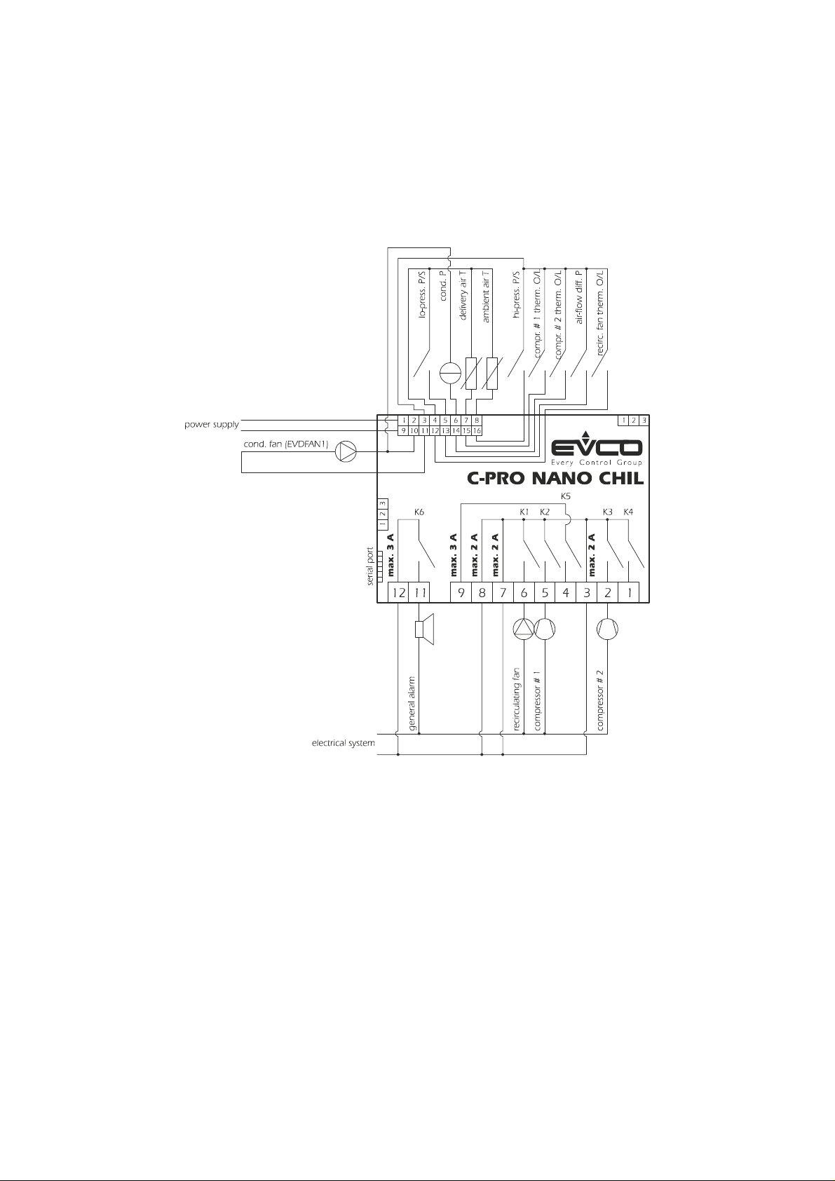
2.1.1 Air-to-air single-circuit chiller units
Using C-PRO NANO CHIL.
Pag. 10
Page 11

C-PRO NANO CHIL AND C-PRO MICRO CHIL – APPLICATION MANUAL
Using C-PRO MICRO CHIL.
Pag. 11
Page 12

C-PRO NANO CHIL AND C-PRO MICRO CHIL – APPLICATION MANUAL
2.1.2 Air-to-air single-circuit chiller units + heat pump
Using C-PRO NANO CHIL.
Pag. 12
Page 13

C-PRO NANO CHIL AND C-PRO MICRO CHIL – APPLICATION MANUAL
Using C-PRO MICRO CHIL.
Pag. 13
Page 14
C-PRO NANO CHIL AND C-PRO MICRO CHIL – APPLICATION MANUAL
2.2 Air-to-water single-circuit chiller units and air-to-water
single-circuit chiller units + heat pump
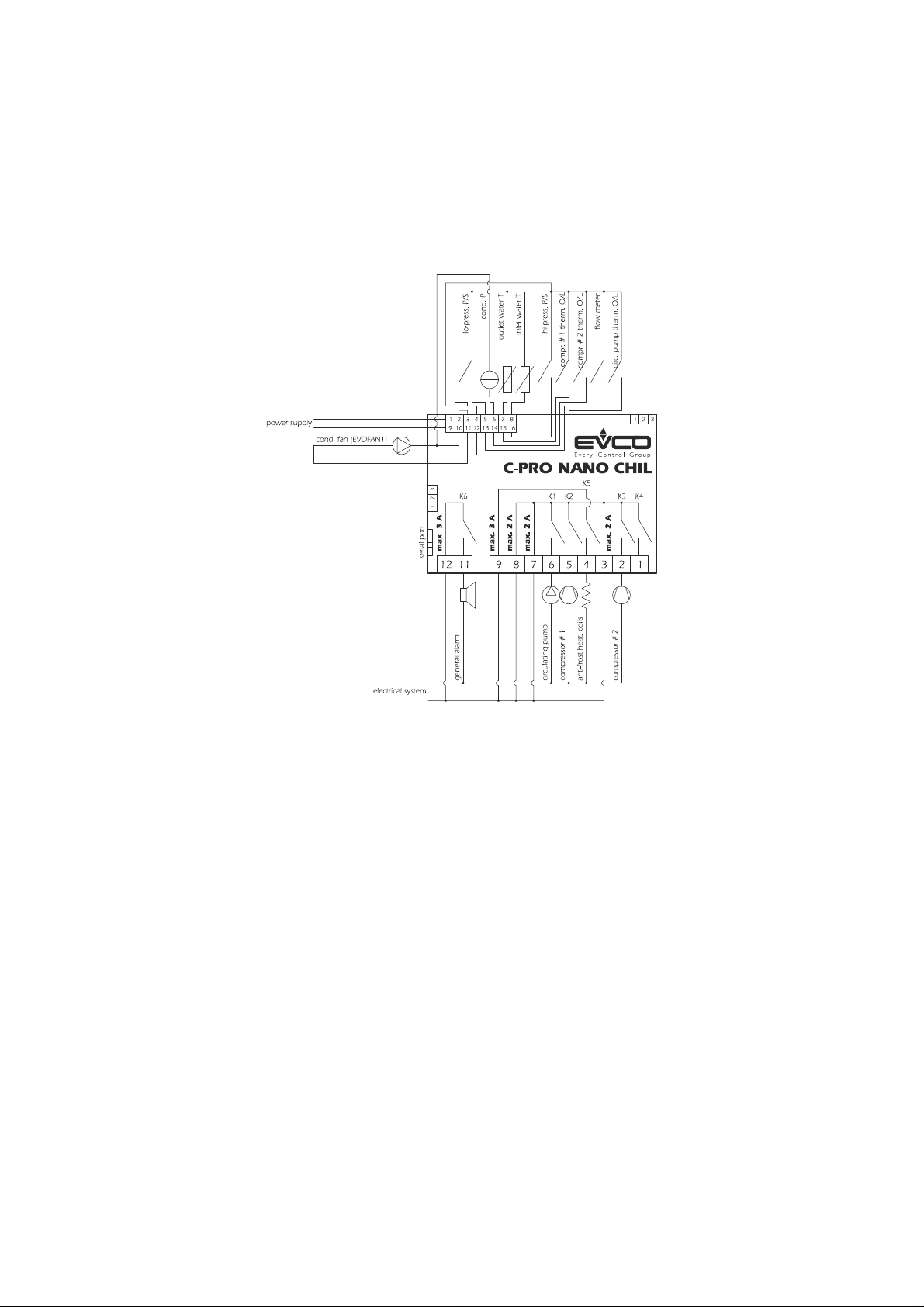
2.2.1 Air-to-water single-circuit chiller units
Using C-PRO NANO CHIL.
Pag. 14
Page 15

C-PRO NANO CHIL AND C-PRO MICRO CHIL – APPLICATION MANUAL
Using C-PRO MICRO CHIL.
Pag. 15
Page 16

C-PRO NANO CHIL AND C-PRO MICRO CHIL – APPLICATION MANUAL
2.2.2 Air-to-water single-circuit chiller units + heat pump
Using C-PRO NANO CHIL.
Pag. 16
Page 17

C-PRO NANO CHIL AND C-PRO MICRO CHIL – APPLICATION MANUAL
Using C-PRO MICRO CHIL.
Pag. 17
Page 18

C-PRO NANO CHIL AND C-PRO MICRO CHIL – APPLICATION MANUAL
2.3 Water-to-water single-circuit chiller units and water-to-
water single-circuit chiller units + heat pump
2.3.1 Water-to-water single-circuit chiller units
Using C-PRO NANO CHIL.
Pag. 18
Page 19

C-PRO NANO CHIL AND C-PRO MICRO CHIL – APPLICATION MANUAL
Using C-PRO MICRO CHIL.
Pag. 19
Page 20

C-PRO NANO CHIL AND C-PRO MICRO CHIL – APPLICATION MANUAL
2.3.2 Water-to-water single-circuit chiller units + heat pump
Using C-PRO NANO CHIL.
Pag. 20
Page 21

C-PRO NANO CHIL AND C-PRO MICRO CHIL – APPLICATION MANUAL
Using C-PRO MICRO CHIL.
Pag. 21
Page 22

C-PRO NANO CHIL AND C-PRO MICRO CHIL – APPLICATION MANUAL
2.4 Single-circuit motocondensing air-based units and single-
circuit motocondensing air-based units with cycle inversion
2.4.1 Single-circuit motocondensing air-based units
Using C-PRO NANO CHIL.
Pag. 22
Page 23

C-PRO NANO CHIL AND C-PRO MICRO CHIL – APPLICATION MANUAL
Using C-PRO MICRO CHIL.
Pag. 23
Page 24

C-PRO NANO CHIL AND C-PRO MICRO CHIL – APPLICATION MANUAL
2.4.2 Single-circuit motocondensing air-based units with cycle inversion
Using C-PRO NANO CHIL.
Pag. 24
Page 25

C-PRO NANO CHIL AND C-PRO MICRO CHIL – APPLICATION MANUAL
Using C-PRO MICRO CHIL.
Pag. 25
Page 26

C-PRO NANO CHIL AND C-PRO MICRO CHIL – APPLICATION MANUAL
2.5 Single-circuit motocondensing water-based units and single-
circuit motocondensing water-based units with cycle
inversion
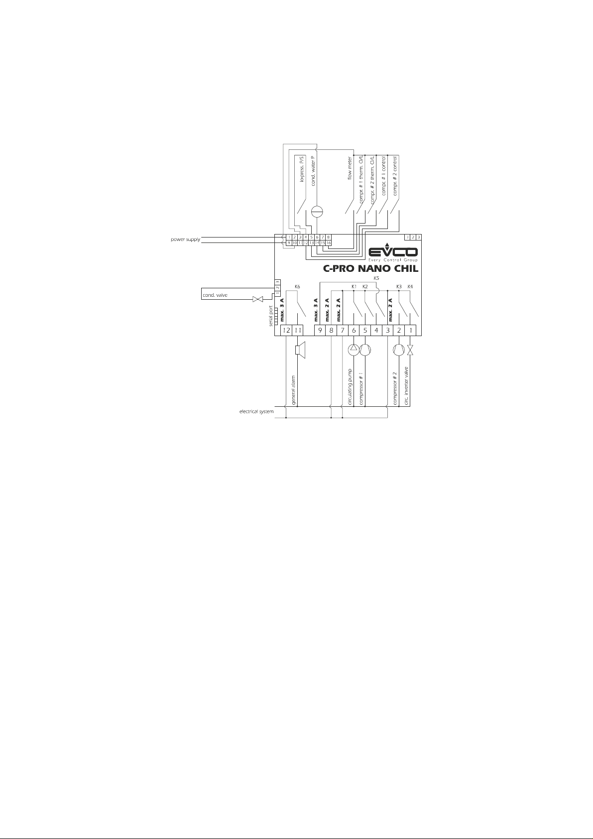
2.5.1 Single-circuit motocondensing water-based units
Using C-PRO NANO CHIL.
Pag. 26
Page 27

C-PRO NANO CHIL AND C-PRO MICRO CHIL – APPLICATION MANUAL
Using C-PRO MICRO CHIL.
Pag. 27
Page 28
C-PRO NANO CHIL AND C-PRO MICRO CHIL – APPLICATION MANUAL
2.5.2 Single-circuit motocondensing water-based units with cycle inversion
Using C-PRO NANO CHIL.
Pag. 28
Page 29

C-PRO NANO CHIL AND C-PRO MICRO CHIL – APPLICATION MANUAL
Using C-PRO MICRO CHIL.
Pag. 29
Page 30

C-PRO NANO CHIL AND C-PRO MICRO CHIL – APPLICATION MANUAL
2.6 Air-to-air twin-circuit chiller units and air-to-air twin-circuit
chiller units + heat pump
2.6.1 Air-to-air twin-circuit chiller units
Using C-PRO NANO CHIL and C-PRO EXP MICRO.
The power supplies of C-PRO NANO CHIL and C-PRO EXP MICRO must be galvanically isolated from each
other.
Pag. 30
Page 31

C-PRO NANO CHIL AND C-PRO MICRO CHIL – APPLICATION MANUAL
Using C-PRO MICRO CHIL and C-PRO EXP MICRO.
The power supplies of C-PRO MICRO CHIL and C-PRO EXP MICRO must be galvanically isolated from each
other.
Pag. 31
Page 32

C-PRO NANO CHIL AND C-PRO MICRO CHIL – APPLICATION MANUAL
2.6.2 Air-to-air twin-circuit chiller units + heat pump
Using C-PRO NANO CHIL and C-PRO EXP MICRO.
The power supplies of C-PRO NANO CHIL and C-PRO EXP MICRO must be galvanically isolated from each
other.
Pag. 32
Page 33

C-PRO NANO CHIL AND C-PRO MICRO CHIL – APPLICATION MANUAL
Using C-PRO MICRO CHIL and C-PRO EXP MICRO.
The power supplies of C-PRO MICRO CHIL and C-PRO EXP MICRO must be galvanically isolated from each
other.
Pag. 33
Page 34

C-PRO NANO CHIL AND C-PRO MICRO CHIL – APPLICATION MANUAL
2.7 Air-to-water twin-circuit chiller units and air-to-water twin-
circuit chiller units + heat pump
2.7.1 Air-to-water twin-circuit chiller units
Using C-PRO NANO CHIL and C-PRO EXP MICRO.
The power supplies of C-PRO NANO CHIL and C-PRO EXP MICRO must be galvanically isolated from each
other.
Pag. 34
Page 35

C-PRO NANO CHIL AND C-PRO MICRO CHIL – APPLICATION MANUAL
Using C-PRO MICRO CHIL and C-PRO EXP MICRO.
The power supplies of C-PRO MICRO CHIL and C-PRO EXP MICRO must be galvanically isolated from each
other.
Pag. 35
Page 36

C-PRO NANO CHIL AND C-PRO MICRO CHIL – APPLICATION MANUAL
2.7.2 Air-to-water twin-circuit chiller units + heat pump
Using C-PRO NANO CHIL and C-PRO EXP MICRO.
The power supplies of C-PRO NANO CHIL and C-PRO EXP MICRO must be galvanically isolated from each
other.
Pag. 36
Page 37

C-PRO NANO CHIL AND C-PRO MICRO CHIL – APPLICATION MANUAL
Using C-PRO MICRO CHIL and C-PRO EXP MICRO.
The power supplies of C-PRO MICRO CHIL and C-PRO EXP MICRO must be galvanically isolated from each
other.
Pag. 37
Page 38

C-PRO NANO CHIL AND C-PRO MICRO CHIL – APPLICATION MANUAL
2.8 Water-to-water twin-circuit chiller units and water-to-water
twin-circuit chiller units + heat pump
2.8.1 Water-to-water twin-circuit chiller units
Using C-PRO NANO CHIL and C-PRO EXP MICRO.
The power supplies of C-PRO NANO CHIL and C-PRO EXP MICRO must be galvanically isolated from each
other.
Pag. 38
Page 39

C-PRO NANO CHIL AND C-PRO MICRO CHIL – APPLICATION MANUAL
Using C-PRO MICRO CHIL and C-PRO EXP MICRO.
The power supplies of C-PRO MICRO CHIL and C-PRO EXP MICRO must be galvanically isolated from each
other.
Pag. 39
Page 40

C-PRO NANO CHIL AND C-PRO MICRO CHIL – APPLICATION MANUAL
2.8.2 Water-to-water twin-circuit chiller units + heat pump
Using C-PRO NANO CHIL and C-PRO EXP MICRO.
The power supplies of C-PRO NANO CHIL and C-PRO EXP MICRO must be galvanically isolated from each
other.
Pag. 40
Page 41

C-PRO NANO CHIL AND C-PRO MICRO CHIL – APPLICATION MANUAL
Using C-PRO MICRO CHIL and C-PRO EXP MICRO.
The power supplies of C-PRO MICRO CHIL and C-PRO EXP MICRO must be galvanically isolated from each
other.
Pag. 41
Page 42

C-PRO NANO CHIL AND C-PRO MICRO CHIL – APPLICATION MANUAL
2.9 Twin-circuit motocondensing air-based units and twin-
circuit motocondensing air-based units with cycle inversion
2.9.1 Twin-circuit motocondensing air-based units
Using C-PRO NANO CHIL and C-PRO EXP MICRO.
The power supplies of C-PRO NANO CHIL and C-PRO EXP MICRO must be galvanically isolated from each
other.
Pag. 42
Page 43

C-PRO NANO CHIL AND C-PRO MICRO CHIL – APPLICATION MANUAL
Using C-PRO MICRO CHIL and C-PRO EXP MICRO.
The power supplies of C-PRO MICRO CHIL and C-PRO EXP MICRO must be galvanically isolated from each
other.
Pag. 43
Page 44

C-PRO NANO CHIL AND C-PRO MICRO CHIL – APPLICATION MANUAL
2.9.2 Twin-circuit motocondensing air-based units with cycle inversion
Using C-PRO NANO CHIL and C-PRO EXP MICRO.
The power supplies of C-PRO NANO CHIL and C-PRO EXP MICRO must be galvanically isolated from each
other.
Pag. 44
Page 45

C-PRO NANO CHIL AND C-PRO MICRO CHIL – APPLICATION MANUAL
Using C-PRO MICRO CHIL and C-PRO EXP MICRO.
The power supplies of C-PRO MICRO CHIL and C-PRO EXP MICRO must be galvanically isolated from each
other.
Pag. 45
Page 46

C-PRO NANO CHIL AND C-PRO MICRO CHIL – APPLICATION MANUAL
2.10 Twin-circuit motocondensing water-based units and twin-
circuit motocondensing water-based units with cycle
inversion
2.10.1 Twin-circuit motocondensing water-based units
Using C-PRO NANO CHIL and C-PRO EXP MICRO.
The power supplies of C-PRO NANO CHIL and C-PRO EXP MICRO must be galvanically isolated from each
other.
Pag. 46
Page 47

C-PRO NANO CHIL AND C-PRO MICRO CHIL – APPLICATION MANUAL
Using C-PRO MICRO CHIL and C-PRO EXP MICRO.
The power supplies of C-PRO MICRO CHIL and C-PRO EXP MICRO must be galvanically isolated from each
other.
Pag. 47
Page 48

C-PRO NANO CHIL AND C-PRO MICRO CHIL – APPLICATION MANUAL
2.10.2 Twin-circuit motocondensing water-based units with cycle inversion
Using C-PRO NANO CHIL and C-PRO EXP MICRO.
The power supplies of C-PRO NANO CHIL and C-PRO EXP MICRO must be galvanically isolated from each
other.
Pag. 48
Page 49

C-PRO NANO CHIL AND C-PRO MICRO CHIL – APPLICATION MANUAL
Using C-PRO MICRO CHIL and C-PRO EXP MICRO.
The power supplies of C-PRO MICRO CHIL and C-PRO EXP MICRO must be galvanically isolated from each
other.
Pag. 49
Page 50

C-PRO NANO CHIL AND C-PRO MICRO CHIL – APPLICATION MANUAL
c
o
n
n
e
c
t
o
r
#
3
(
i
f
r
e
q
u
e
s
t
e
d
)
connector # 5
connector # 4
connector # 1
C-PRO NANO CHIL
m
a
x
.
2
A
m
a
x
.
3
A
m
a
x
.
3
A
m
a
x
.
2
A
m
a
x
.
2
A
connector # 1
connector # 4
connector # 5
C-PRO MICRO CHIL
c
o
n
n
e
c
t
o
r
#
2
213
2.11 Connection Layout of C-PRO MICRO CHIL and C-PRO
EXP MICRO
2.11.1 Connection layout of C-PRO NANO CHIL and C-PRO MICRO CHIL
The connection layout of C-PRO NANO CHIL and C-PRO MICRO CHIL is shown below, with
related tables explaining the meaning of inputs and outputs.
C-PRO NANO CHIL:
connector # 2
C-PRO MICRO CHIL:
5136
4
10311
2
1
K6 K1 K2
12
14715816
K5
4 2
3 157 69 81112
1192
K3 K4
233
1
42 3 5 76 98 112112
K1 K2 K3 K4 K5 K6
16
15
7
8
max. 3 A
1461351241131029
max. 3 A
1
max. 3 A
connector # 3 (if requested)
max. 4 A
max. 3 A
3
Pag. 50
Page 51

C-PRO NANO CHIL AND C-PRO MICRO CHIL – APPLICATION MANUAL
Connector 1: Connection for relay outputs
C-PRO NANO CHIL
Conn. Label Description
C1-1 DO4 Normally open contact relay # 4
C1-2 DO3 Normally open contact relay # 3
C1-3 COMMON 1 Common relays # 1, 2, 3, 4
C1-4 DO5 Normally open contact relay # 5
C1-5 DO2 Normally open contact relay # 2
C1-6 DO1 Normally open contact relay # 1
C1-7 COMMON 1 Common relays # 1, 2, 3, 4
C1-8 COMMON 1 Common relays # 1, 2, 3, 4
C1-9 COMMON DO5 Common relay # 5
C1-10 Not in use
C1-11 DO6 Normally open contact relay # 6
C1-12 COMMON DO6 Common relay # 6
C-PRO NANO CHIL
Connector 1: Connection for relay outputs
Conn. Label Description
C1-1 DO1 Normally open contact relay # 1
C1-2 COMMON DO1 Common relay # 1
C1-3 DO2 Normally open contact relay # 2
C1-4 COMMON DO2 Common relay # 2
C1-5 DO3 Normally open contact relay # 3
C1-6 COMMON DO3 Common relay # 3
C1-7 DO4 Normally open contact relay # 4
C1-8 COMMON 1 Common relays # 4, 5
C1-9 DO5 Normally open contact relay # 5
C1-10 Not in use
C1-11 DO6 Normally open contact relay # 6
C1-12 COMMON DO6 Common relay # 6
Connector 2: Connection for EVKEY (parameter upload/download key) and output for
TTL-RS-485 module.
Connector 3: Connector for optional analogue outputs (AO2 and AO3)
Conn. Label Description (Version V+I)
C3-1 OUT1 0-10 V dc
C3-2 GND Common analogue output
C3-3 OUT2 0(4)-20 mA
Description (Version I+I)
C3-1 OUT1 0(4)-20 mA
C3-2 GND Common analogue output
C3-3 OUT2 0(4)-20 mA
Description (Version V+V)
C3-1 OUT1 0-10 V dc
C3-2 GND Common analogue output
C3-3 OUT2 0-10 V dc
Pag. 51
Page 52

C-PRO NANO CHIL AND C-PRO MICRO CHIL – APPLICATION MANUAL
Connector 4: Connector for low-voltage signals
Conn. Label Description
C4-1 12 V AC (power
supply)
C4-2 Not connected Not connected
C4-3 GND Common analogue and digital inputs
C4-4 GND Common analogue and digital inputs
C4-5 AI4 Analogue input # 4 (NTC probe, 0-20 or 4-20 mA transducer)
C4-6 AI3 Analogue input # 3 (NTC probe, 0-20 or 4-20 mA transducer)
C4-7 AI2 Analogue input # 2 (NTC probe)
C4-8 AI1 Analogue input # 1 (NTC probe)
C4-9 12 V AC (power
supply)
C4-10 12 V DC Power supply for current transducers and EVCO’s EVDFAN1 phase-cut
C4-11 AO1 Output for EVCO’s EVDFAN1 phase-cut module
C4-12 DI5 Digital input # 5
C4-13 DI4 Digital input # 4
C4-14 DI3 Digital input # 3
C4-15 DI2 Digital input # 2
C4-16 DI1 Digital input # 1
To enable the use of the EVDFAN1 phase-cut module, the controller must be powered by an alternating
current supply; the controller’s powering phase must be the same one that supplies the module.
Connector 5: Connector for EVCO remote keyboard / expansion
Conn. Label Description
C5-1 12 V DC Power supply for remote keyboard (12 V DC, 50 mA max.)
C5-2 GND Common
C5-3 SERIAL EVCO live serial port
Instrument power supply (12 V AC/DC)
Instrument power supply (12 V AC/DC)
module (12 V DC)
The power supplies of the controller and the expansion must be galvanically isolated from each other.
Pag. 52
Page 53

C-PRO NANO CHIL AND C-PRO MICRO CHIL – APPLICATION MANUAL
11
12
connector # 1
connector # 3
connector # 5
CONTROLLER
2.11.2 Connection layout of C-PRO EXP MICRO
The connection layout of C-PRO EXP MICRO is shown below, with related tables explaining the
meaning of inputs and outputs.
1
K7 K8 K9 K10 K11 K12
42 3 5 76 98
max. 3 A
max. 3 A
max. 3 A
max. 4 A
max. 3 A
C-PRO MICROEXP
1681571461351241131029
connector # 2
1
221
3
1
3
Connector 1: Connection for relay outputs
Conn. Label Description
C1-1 DO7 Normally open contact relay # 7
C1-2 COMMON DO7 Common relay # 7
C1-3 DO8 Normally open contact relay # 8
C1-4 COMMON DO8 Common relay # 8
C1-5 DO9 Normally open contact relay # 9
C1-6 COMMON DO9 Common relay # 9
C1-7 DO10 Normally open contact relay # 10
C1-8 COMMON 1 Common relays # 10, 11
C1-9 DO11 Normally open contact relay # 11
C1-10 Not in use
C1-11 DO12 Normally open contact relay # 12
C1-12 COMMON DO12 Common relay # 12
Connector 2: Connector for low-voltage signals
Conn. Label Description
C2-1 12 V AC (power
supply)
C2-2 Not connected Not connected
C2-3 GND Common analogue and digital inputs
C2-4 GND Common analogue and digital inputs
C2-5 AI8 Analogue input # 8 (4-20 mA transducer)
C2-6 AI7 Analogue input # 7 (4-20 mA transducer)
C2-7 AI6 Analogue input # 6 (NTC probe)
C2-8 AI5 Analogue input # 5 (NTC probe)
Instrument power supply (12 V AC/DC)
Pag. 53
Page 54

C-PRO NANO CHIL AND C-PRO MICRO CHIL – APPLICATION MANUAL
C2-9 12 V AC (power
supply)
C2-10 12 V DC Power supply for current transducers and EVCO’s EVDFAN1 phase-cut
C2-11 AO4 Output for EVCO’s EVDFAN1 phase-cut module
C2-12 DI11 Digital input # 11
C2-13 DI10 Digital input # 10
C2-14 DI9 Digital input # 9
C2-15 DI8 Digital input # 8
C2-16 DI7 Digital input # 7
To enable the use of the EVDFAN1 phase-cut module, the expansion must be powered by an alternating
current supply; the expansion’s powering phase must be the same one that supplies the module.
Connector 3: Connector for the controller
Conn. Label Description
C3-1 12 V DC Power supply (12 V DC, 50 mA max.)
C3-2 GND Common
C3-3 SERIAL EVCO live serial port
Instrument power supply (12 V AC/DC)
module (12 V DC)
The power supplies of the controller and the expansion must be galvanically isolated from each other.
Pag. 54
Page 55

C-PRO NANO CHIL AND C-PRO MICRO CHIL – APPLICATION MANUAL
3 Component Network and Accessories
3.1 Example of C-PRO NANO CHIL
Pag. 55
Page 56

C-PRO NANO CHIL AND C-PRO MICRO CHIL – APPLICATION MANUAL
3.2 Example of C-PRO MICRO CHIL (built-in version)
Pag. 56
Page 57

C-PRO NANO CHIL AND C-PRO MICRO CHIL – APPLICATION MANUAL
3.3 Example of C-PRO MICRO CHIL (blind version)
Pag. 57
Page 58

C-PRO NANO CHIL AND C-PRO MICRO CHIL – APPLICATION MANUAL
4 USER INTERFACE
4.1 Displays and Keyboards
For the application, two types of interface are provided:
⋅ a built-in 4-display interface with 7 segments;
⋅ a remote 4-display interface with 7 segments.
Both interfaces feature 4 keys for navigation/page editing, and differ in their display mode of
certain associated statuses, i.e. via icons (built-in version) or LED (remote version).
For both versions, a description is provided of the keys and LEDs used by the application; indeed,
according to the interface in use, it is possible to manage a different number of keys and LEDs.
Local built-in interface
The built-in interface is integrated into the controller being in use.
C-PRO NANO CHIL
C-PRO MICRO CHIL
(built-in version)
Pag. 58
Page 59

C-PRO NANO CHIL AND C-PRO MICRO CHIL – APPLICATION MANUAL
The keyboard features 4 page navigation and value editing keys, which have the following
functions:
- UP and DOWN: in editing, it modifies parameters; otherwise, it moves the cursor. If
pressed down and held for about 2 seconds during the display of the main page, the UP key
enables the display of the other probes, according to the following table.
tin
tou1
PrS1
tou2
PrS2
tEXt
Evp1
Evp2
tAcc
Inlet temperature probe (---, if disabled)
Circuit 1 outlet temperature probe (---, if disabled)
Circuit 1 condensing pressure probe (---, if disabled)
Circuit 2 outlet temperature probe (---, if disabled)
Circuit 2 condensing pressure probe (---, if disabled)
External temperature probe (---, if disabled)
Circuit 1 evaporating pressure probe (---, if disabled)
Circuit 2 evaporating pressure probe (---, if disabled)
Accumulation temperature probe (---, if disabled)
- SET / ENTER: During editing, it confirms the value; otherwise, it sends any
commands associated to the text where the cursor is positioned. If pressed down and held for
about 2 seconds, the ENTER key enables access to the main menu. If held down during
display of an alarm page, this key enables resetting of the alarm. If alarm pages are being
displayed, every key press scrolls all active alarms.
- STAND-BY / ESC: During editing, it cancels the value; otherwise, it requests any default
page that might be associated with the current page. If pressed down and held for about 2
seconds, the ESC key enables ON/OFF switching of the machine. If pressed in the main
page, this key enables access to the list of al active alarms.
In addition , the following icons are also used:
- Summer icon: This identifies the summer operating mode (chiller): if there is a request from
the thermoregulator, the icon remains lit, otherwise it flashes (stand-by). When the heat
pump is operating, it remains off. Its significance may be exchanged with that of the winter
icon, via parameter PH53.
- Winter icon: This identifies the winter operating mode (heat pump): it the thermoregulator
requests its, it remains lit, otherwise it flashes (stand-by). When the chiller is operating, it
remains off, unless free-cooling is enabled, in which case it flashes rapidly. The significance
may be exchanged with the summer icon via the PH53 parameter.
- Fan icon: This identifies the status of fans. If it is lit, at least one fan is on; if it flashes
slowly, at least one fan is in alarm condition; if it flashes rapidly, at least one fan is
operating in manual mode; otherwise, it remains off.
- Pump icon: This identifies the status of the pump or of the delivery fan. If it is lit, at least
one pump is on; if it flashes rapidly, this indicates that a timing is enabled; if it flashes
slowly, this indicates that at least in one of the two pumps (or delivery fan) thermal
protection has been triggered.
Pag. 59
Page 60

C-PRO NANO CHIL AND C-PRO MICRO CHIL – APPLICATION MANUAL
- Maintenance icon: This identifies a maintenance request. If it is lit, at least one compressor
or fan is operating manually; if it flashes, at least one compressor or fan has exceeded the
number of operating hours; otherwise, it remains off.
- Alarm icon: This identifies the presence of any alarms. If it is lit, alarms are present,
otherwise it remains off. If flashing, it indicates the presence of a new alarm that has yet to
be displayed. When the machine is shut down, the icon flashes in the presence of any
alarms.
- Icons 1, 2 ,3: These identify the status of the individual compressors. If it is lit, the
compressor is on; if it flashes slowly, the compressor is in an alarm condition; rapid flashing
indicates a current timing for an imminent shutdown or start-up; otherwise, it remains off. In
the case of a twin circuit, only icons 1 and 2 are used, to signify the following: lit means that
at least one compressor in that circuit is on; slow flashing means that at least one compressor
is in alarm condition; rapid flashing means that at least one compressor is operating
manually; otherwise, it remains off. These icons are enabled/disabled via the PH51
parameter.
- Anti-frost resistor icon: This identifies the status of setting and of the anti-frost alarm. If it
is lit, resistors are enabled; flashing indicates an active alarm; otherwise, it remains off.
- Stand-by icon: This is linked to the ESC key and identifies the machine status.
Off: The machine is off.
Lit: The machine is on.
Slow flashing: The machine has been shut down by a digital input.
Rapid flashing: The machine has been shut down by a supervisor.
- Defrosting icon: This identifies the defrosting status. If it is lit, a defrosting cycle is in
progress; slow flashing indicates a current timing cycle to start defrosting; rapid flashing
indicates dripping; otherwise, it remains off.
- °C/°F icon: This indicates the temperature measurement unit of the selected probe.
Pag. 60
Page 61

C-PRO NANO CHIL AND C-PRO MICRO CHIL – APPLICATION MANUAL
Remote interface
V LEDi
Panel-mounted version
V WALL
Wall-mounted version
The keyboard features 4 page-navigation and value-editing keys, which have the following
functions:
- UP and DOWN: During editing, it modifies parameters; otherwise, it moves the cursor. If
pressed down and held for about 2 seconds during the display of the main page, the UP key
enables the display of the other probes.
- SET / ENTER: During editing, it confirms the value; otherwise, it sends any commands
associated to the text where the cursor is positioned. If pressed down and held for about 2
seconds, the ENTER key enables access to the main menu. If held down during display of
an alarm page, this key enables resetting of the alarm. If alarm pages are being displayed,
every key press scrolls all active alarms.
- STAND-BY / ESC: During editing, it cancels the value; otherwise, it requests any default
page that might be associated with the current page. If pressed and held down for about 2
seconds, the ESC key enables switching on/freezing of the machine; if pressed in the main
page, it enables access to the list of all active alarms.
In addition, the following LEDs are also used:
- L1 = Summer LED: This identifies the summer operating mode (chiller): in case of a request
from the thermoregulator, it remains lit, otherwise it flashes (stand-by). When the heat pump
is operating, it remains off.
- L2 = Defrosting LED: This identifies the status of defrosting. If it is lit, a defrosting cycle is
in progress; slow flashing indicates a current timing cycle to start defrosting; rapid flashing
indicates dripping; otherwise, it remains off.
- L3 = Winter LED: This identifies the winter operating mode (heat pump): if there is a
request from the thermoregulator, it remains lit, otherwise it flashes (stand-by). When the
chiller is operating, it remains off, unless free-cooling is enabled, in which case it flashes
rapidly.
- L4 = Compressor LED: This identifies the status of compressors. If it is lit, at least one
compressor is on; if it flashes slowly, at least one compressor is in alarm condition; if it
Pag. 61
Page 62

C-PRO NANO CHIL AND C-PRO MICRO CHIL – APPLICATION MANUAL
flashes rapidly, at least one compressor is operating in manual mode; otherwise, it remains
off.
- L5 = Pump LED: This identifies the status of the pump or of the delivery fan. If it is lit, at
least one pump is on; if it flashes rapidly, this indicates that a timing is enabled; if it flashes
slowly, this indicates that at least in one of the two pumps (or delivery fan) a thermal
protection has been triggered.
- L6 = Alarm LED: This identifies the presence of any alarms. If it is lit, alarms are present,
otherwise it remains off. If flashing, it indicates the presence of a new alarm that has yet to
be displayed. When the machine is switched off, the LED flashes in the presence of any
alarms.
4.2 List of Pages
This chapter describes the main pages and menus featured in the application. As already described
earlier, the general menu is subdivided into four levels: user, maintenance operator, installation
operator, and constructor.
The menu structure is the following:
⋅ General Menu
⋅ User menu (Level 1)
⋅ Maintenance operator menu (Level 2)
o Operating branch maintenance menu
o Manual branch maintenance menu
o Calibration branch maintenance menu
o Input/output branch maintenance menu
⋅ Installation operator menu (Level 3)
o Compressor branch installation menu
o Setting branch installation menu
o Condensation branch installation menu
o Defrosting branch installation menu
o Pump branch installation menu
o Anti-frost branch installation menu
o Free-cooling branch installation menu
o Safety device branch installation menu
o Miscellaneous branch installation menu
⋅ Constructor menu (Level 4)
o Plant branch constructor menu (configuration wizard)
o Hardware branch constructor menu
o Parameter branch installation menu
Password
Each menu is assigned a level, which affects the accessibility of the various menus.
Each level is assigned a password, which enables access to the various functions featured in that
menu; once the correct password has been entered, protected functions become accessible. Entering
of the correct password has two consequences:
⋅ unlocking of the related level;
Pag. 62
Page 63

C-PRO NANO CHIL AND C-PRO MICRO CHIL – APPLICATION MANUAL
⋅ unlocking of its sublevels.
All level passwords can be modified from the same level or from higher levels. For example, from
the constructor level it will be possible to modify all passwords of underlying levels, by using the
appropriate page.
The range of values that can be set for a password is -999 / 9999.
After 4 minutes have elapsed without any key being pressed, the password expires and it is
necessary to reset it.
Main Page
The main display page varies according to the machine status, i.e. on or off:
- If the machine is switched OFF, OFF is displayed, or OFFd, if the cause for the
shutdown is a lack of consensus from digital input; otherwise OFFS is displayed, if
the shutdown is due to supervisor.
- If the machine is switched ON, the inlet temperature value is displayed (PC11=0),
the outlet value (PC11=1), or the required power (PC11=2), according to the setting
type (parameter PC11). In twin-circuit units, the average value of the two outlet
temperatures is displayed. If the probe is faulty o disconnected, “Err” is displayed.
From this page, by pressing the DOWN key for about 2 seconds, it is possible to display all
configured probes. In case of fault status of the probes, the value field of the corresponding probe
displays Err, or else --- if the probe is disabled.
Pressing the ESC key from this page brings the user back to the main page.
General Menu
The general menu has no levels and represents the access point to all other system menus.
USEr (USER Menu)
MAin ( MAINTENANCE Menu)
InSt (INSTALLATION Menu)
CoSt (CONSTRUCTOR Menu)
StAt (MACHINE STATUS Menu)
This menu can be displayed from any point of the user interface, holding down the ENTER key for
about 2 seconds. From this page, it possible to choose which menu to access via the UP and DOWN
keys, and then pressing the ENTER key to confirm the choice.
Pressing the ESC key from this menu, the user returns to the initial page, if the machine is switched
ON; or else to the OFF page, if the machine is OFF.
Pag. 63
Page 64

C-PRO NANO CHIL AND C-PRO MICRO CHIL – APPLICATION MANUAL
StAt Menu
Selecting the StAt item from the general menu, the user enters the display of some of the plant’s
main statuses:
Unit: indicates the machine’s current operating status (OFF, ChIL, pdC, dEFr, dRIp, F-
C).
tdF1: accumulated waiting time for a defrosting cycle of circuit # 1.
dFr1: duration time of defrosting of circuit # 1.
tdF2: accumulated waiting time for a defrosting cycle of circuit # 2.
dFr2: duration time of defrosting of circuit # 2.
SEtC: current set point for summer operation.
SEtH: current set point for winter operation.
PREq: power requirement [%]
PSup: power output [%]
CMP1, CMP2 .. CMP6: status of compressors (dIS, OFF, tOn, On, tOFF, ALAr,
MAnU).
FAn1, FAn 2: status of fans (dIS, OFF, tOn, On, tOFF, ALAr, MAnU).
InF1,InF2: speed of condensing fans [%]
InFC: value of free-cooling fan [%] (with separate air circuit, otherwise 0).
PMP1, PMP2: status of pumps (dIS, OFF, On, ALAr).
Pressing the ENTER key over the label, the corresponding status value is displayed, while pressing
the ESC key the display returns to the general menu. This menu has no password protection.
User Menu
The user menu is a Level 1 menu, i.e. it requires entering of the user level (or higher) password, in
order to be able to display/modify the parameters contained in this branch.
MOdE (summer/winter operating mode)
SPC1 (summer set point)
SPH1 (winter set point)
SSC1 (summer set point offset)
SSH1 (winter set point offset)
PSd1 (USER password)
It is possible to modify the various set points and offsets for the secondary set point.
Maintenance Operator Menu
The user menu is a Level 2 menu, i.e. it requires entering of the maintenance operator level (or
higher) password, in order to be able to display/modify the parameters contained in this branch.
Func (OPERATION menu)
MAnu (MANUAL menu)
CAL (CALIBRATION menu)
I-O (I/O STATUS menu)
PSd2 (MAINTENANCE OPERATOR password)
In this menu, it is possible to view the status of the various devices, inputs and outputs utilised by
the application.
Pag. 64
Page 65

C-PRO NANO CHIL AND C-PRO MICRO CHIL – APPLICATION MANUAL
In the OPERATION menu, it is possible to view/enable the features relating to the operation of
compressors, fans and pumps. Some examples of these are the hours of operation, the enabling of
the corresponding alarm and the threshold of maximum allowable hours.
In the MANUAL menu, it is possible to set to manual/automatic operation compressors and fans,
whose outputs can be forced, in order to test their functionality.
In the CALIBRATION menu, it is possible to set the corrections to be applied to analogue inputs, to
compensate the offsets due to cabling and probe positioning.
In the I/O STATUS menu, it is possible to view directly the card’s physical inputs and outputs.
Installation Operator Menu
The installation operator menu is a Level 3 menu, i.e. it requires entering of the installation operator
level (or higher) password, in order to be able to display/modify the parameters contained in this
branch.
CoMP (COMPRESSORS menu)
rEG (REGULATION menu)
Cond (CONDENSATION menu)
dEFr (DEFROSTING menu)
PuMP (PUMPS menu)
A-Fr (ANTI-FROST menu)
F-C (FREE-COOLING menu)
SEcu (SAFETY DEVICES menu)
PAr (VARIOUS PARAMETERS menu)
MAP (PARAMETER MAPS menu)
PSd3 (INSTALLATION OPERATOR password)
The installation operator menu contains all the parameters connected with the configuration of all
functionalities (alarms, settings, logic, rotation type, etc.) of the machine.
In the COMPRESSORS menu, it is possible to set the parameters connected with the management of
devices:
⋅ rotation
⋅ timings
⋅ maximum number of start-ups.
In the REGULATIONS menu, it is possible to set the parameters connected with lateral-band and
neutral-zone thermal regulation of compressors.
In the CONDENSATION menu, it is possible to set the parameters connected with the control of
condensation pressure, via the fans.
In the PUMPS menu, it is possible to set the parameters connected with operation and protection of
pumps.
In the DEFROSTING menu, it is possible to set the parameters connected with the activation and
duration of heat pump defrosting.
Pag. 65
Page 66

C-PRO NANO CHIL AND C-PRO MICRO CHIL – APPLICATION MANUAL
In the ANTI-FROST menu, it is possible to set the parameters connected with the thermal
regulation of resistors and control of the anti-frost alarm.
In the FREE-COOLING menu, it is possible to set the parameters connected with the enabling,
operation and activation of the free-cooling function.
The SAFETY DEVICES menu contains all parameters connected with alarms and management of
safety devices which protect the refrigerating circuit:
⋅ activations
⋅ reporting delays
⋅ type of resetting …
The VARIOUS PARAMETERS menu contains other general parameters connected with the
management of Modbus communications, transducer full-scale values and other configurable
activations.
The PARAMETER MAPS menu is accessible only with the machine in OFF mode. In this menu, it
is possible to re-establish factory-set parameters and to save or reload parameters from a
programming key. After each operation, it is necessary to switch OFF and then back ON the device.
Constructor Menu
The constructor menu is a Level 4 menu, i.e. it requires entering of the constructor level password,
in order to be able to display/modify the parameters contained in this branch. Furthermore, this
level is only accessible with the machine in OFF mode.
ConF (PLANT menu)
Hard (INPUT AND OUTPUT HARDWARE menu)
PSd4 (CONSTRUCTOR password)
This menu contains all the machine’s configuration parameters, which determine its operation mode
and which functionalities are to be enabled or disabled, according to the constructor’s requirements.
The PLANT menu contains a plant configuration wizard, which is used to set the number of circuits,
the number of compressors, the number of fans and the number of protection devices to be used
Once the configuration has been completed, a summary page is displayed, showing the configured
relays and digital inputs, with an indication of any need to use an expansion.
HARDWARE menus contain all parameters used for setting the positions to which the various
devices are to be connected.
⋅ Position of digital outputs of pumps, compressors and fans;
⋅ Position of inverter to be connected to analogue outputs;
⋅ Position of digital inputs/outputs of alarms.
Note: By setting the position of the various alarm inputs, their functionality is also enabled. Indeed,
an alarm is only enabled if the parameter which identifies its actual physical position on the
terminal has been set and is different from zero. If an alarm is not to be used, it is sufficient to leave
its corresponding parameter set to zero.
The same system is used to manage outputs, e.g. those of alarm relays: if position parameters have a
zero value, relay commands are disabled.
Pag. 66
Page 67

C-PRO NANO CHIL AND C-PRO MICRO CHIL – APPLICATION MANUAL
Project and Firmware Versions
Press simultaneously the UP+DOWN keys for about 2 seconds, then press the ENTER key on the
InFo label.
Information on the project and controller firmware versions is displayed sequentially, namely:
Project Number <-> Project Version <-> Project Revision <->
Firmware Number <-> Firmware Version <-> Firmware Revision <->
To scroll this information, use the UP and DOWN keys. To return to the application pages, press
the ESC key.
Pag. 67
Page 68

C-PRO NANO CHIL AND C-PRO MICRO CHIL – APPLICATION MANUAL
5 Parameter List
All parameters managed by the application are listed below. Each parameter is accompanied by a
brief description, the range of its admissible values, units of measure, the assigned default value and
the menu containing the parameter. Menu are structured on the basis of the following logic:
⋅ UT : User menu
⋅ MA: Maintenance operator menu
o MA-F: Operation branch maintenance menu
o MA-M: Manual branch maintenance menu
o MA-CA: Calibration branch maintenance menu
o MA-IO: Input/output branch maintenance menu
⋅ IS : Installation operator menu
o IS-R: Regulation branch installation menu
o IS-C: Compressor branch installation menu
o IS-F: Condensing fan branch installation menu
o IS-D: Defrosting branch installation menu
o IS-P: Pump branch installation menu
o IS-A: Anti-frost branch installation menu
o IS-FC: Free-cooling branch installation menu
o IS-S: Protection device branch installation menu
o IS-V: Various parameter branch installation menu
⋅ CO : Constructor menu
o CO-W: Plant branch construction menu
o CO-Hw: Hardware branch construction menu
o CO-Pa: Parameter branch installation menu
Pag. 68
Page 69

C-PRO NANO CHIL AND C-PRO MICRO CHIL – APPLICATION MANUAL
5.1 List of Configuration Parameters
Code
It sets the operating mode:
ModE
0: CooL, (Chiller/summer)
1: hEAt (Heat pump/winter)
SPC1
SSC1
SPH1
SSH1
It sets the value of the summer set point
(chiller)
It sets the offset value for the utilisation of the
secondary summer set point.
It sets the value of the winter set point (heat
pump).
It sets the offset value for the utilisation of the
secondary summer set point.
PSd1 It modifies the password at User level. 0 -999 9999 UT
It sets – in tens – the maximum number of
PM00
operating hours of compressors. When this
limit is exceeded, the connected alarm is
triggered.
PM01
PM02
PM03
PM04
PM05
It shows – in tens – the number of operating
hours of compressors. One parameter for each
compressor.
PM06
It sets – in tens – the maximum number of
PM30
operating hours of pumps / delivery fan. When
this limit is exceeded, the connected alarm is
triggered.
PM31
PM32
It shows – in tens – the number of operating
hours of the first pump / delivery fan.
It shows – in tens – the number of operating
hours of the second pump.
It sets – in tens – the maximum number of
PM40
operating hours of fans. When this limit is
exceeded, the connected alarm is triggered.
It shows – in tens – the number of operating
PM41
hours of the first fan or of the inverter in
Circuit # 1.
It shows – in tens – the number of operating
PM42
hours of the second fan or of the inverter in
Circuit # 2.
PM91
PM92
PM93
PM11
PM12
It sets the date (year) when the last plant
maintenance was carried out.
It sets the date (month) when the last plant
maintenance was carried out.
It sets the date (day) when the last plant
maintenance was carried out.
It enables the manual/automatic operation of
the compressor.
Parameter Description Default Min. Max. M.U. Menu Notes
USER PARAMETERS
0 0 1 UT
8.5 PC21 PC22 °C UT
0.0 -20.0 20.0 °C UT
44.0 PC23 PC24 °C UT
0.0 -20.0 20.0 °C UT
MAINTENANCE PARAMETERS
hours
2000 0 9999
x
10
MA-F
hours
0 0 9999
x
10
MA-F
hours
2000 0 9999
x
10
MA-F
hours
0 0 9999
x
10
MA-F
hours
0 0 9999
x
10
MA-F
hours
2000 0 9999
x
10
MA-F
hours
0 0 9999
x
10
MA-F
hours
0 0 9999
x
10
MA-F
MA-
2007 2007 2060
F«
1 1 12 MA-F
1 1 31 MA-F
0 0 1 MA-M
Modifiable only
if the units is a
chiller + heat
pump:
(PG00=2,4,6,8,1
0 e PG08=0)
Pag. 69
Page 70

C-PRO NANO CHIL AND C-PRO MICRO CHIL – APPLICATION MANUAL
PM13
PM14
PM15
0: Auto – normal operation
1: Manu – manual operation
One for each compressor.
PM16
PM21
PM22
PM23
PM24
PM25
PM26
During manual operation, it forces the start-
up/shutdown of the compressor. 0: switches
the compressor OFF
1: switches the compressor ON
One for each compressor.
0 0 1 MA-M
It enables the manual/automatic operation of
PM51
the condensing fan in Circuit # 1.
0: Auto – normal operation
0 0 1 MA-M
1: Manu – manual operation
It enables the manual/automatic operation of
PM52
the condensing fan in Circuit # 2.
0: Auto – normal operation
0 0 1 MA-M
1: Manu – manual operation
PM61
PM62
During manual operation, it forces the value of
the condensing fan in Circuit # 1.
During manual operation, it forces the value of
the condensing fan in Circuit # 2.
0.0 0.0 100.0 % MA-M
0.0 0.0 100.0 % MA-M
It enables the manual/automatic operation of
PM71
the free-cooling fan.
0: Auto – normal operation
0.0 0.0 100.0 % MA-M
1: Manu – manual operation
PM72
PM81
PM82
PM83 Calibration of condensing probe in Circuit # 1 0.0 -20.0 20.0 Bar
PM84 Calibration of the AI04 probe 0.0 -20.0 20.0 Bar/°C
PM85 Calibration of the AI05 probe 0.0 -20.0 20.0 °C
PM86
PM87 Calibration of AI07 pressure probe 0.0 -20.0 20.0 Bar
PM88 Calibration of AI08 pressure probe 0.0 -20.0 20.0 Bar
PSd2
During manual operation, it forces the value of
the free-cooling fan.
Calibration of the input (ambient) temperature
probe
Calibration of outlet (delivery) temperature
probe # 1
Calibration of outlet (delivery) temperature
probe # 2
It modifies the password at Maintenance
Operator level.
0.0 0.0 100.0 % MA-M
0.0 -20.0 20.0 °C
0.0 -20.0 20.0 °C
0.0 -20.0 20.0 °C
MA-CA
MA-CA
MA-CA
MA-CA
MA-CA
MA-CA
MA-CA
MA-CA
0 -999 9999 MA-F
INSTALLATION OPERATOR PARAMETERS
COMPRESSOR PARAMETERS
Rotation type used for compressor
management:
PC01
0: FIFO
1: LIFO
0 0 3 IS-C
2: FIFO + hours
3: LIFO + hours
Enabling mode of compressors in the two
PC02
circuits:
0: Circuit balancing
0 0 1 IS-C
1: Circuit saturation
Min. time for which the compressor must
PC04
remain ON, even if a shutdown has been
20 0 999 Sec. IS-C
requested.
Min. time for which the compressor must
PC05
remain OFF, even if a start-up has been
120 0 999 Sec. IS-C
requested.
PC06 Min. time which must elapse between two 360 0 999 Sec. IS-C
Only on twin
circuits
Pag. 70
Page 71

C-PRO NANO CHIL AND C-PRO MICRO CHIL – APPLICATION MANUAL
start-ups of the same compressor.
PC07
PC08
PC09
PC10
PC11
PC12
PC14
PC15 Min. value of compressor neutral zone 1.0 0.1 10.0 °C IS-R
PC16 Max. value of compressor neutral zone 5.0 0.1 10.0 °C IS-R
PC17
PC18
PC21
PC22
PC23
PC24
PC30 Enabling of power limiting from digital input No (0) No (0) Yes (1) IS-R
PC31 Power limiting for summer 50 0 100 % IS-R
PC32 Power limiting for winter 50 0 100 % IS-R
PC35 Enabling of forced shutdown of compressors No (0) No (0) Yes (1) IS-R
PC36 Summer forced shutdown set point 3.5 -30.0 23.0 °C IS-R
PC37 Winter forced shutdown set point 52.0 26.0 75.0 °C IS-R
PC41
PC42 Compressor shutdown time in pump-down 5 0 240 Sec. IS-R
PC43 Relative threshold for pump-down disabling 1.5 0.0 5.0 Bar IS-R
PC45
PC46
PC47
PC48
PC49
PC50
PC51 3.2 0.0 10.0 Bar IS-R
PC52
PC53 External low temperature threshold for -5.0 -10.0 5.0 °C IS-R
Min. time which must elapse between startups of two different compressors.
Min. time which must elapse between
shutdowns of two different compressors.
Max. number of start-ups for every hour (only
for adaptive regulation).
Number of compressors per circuit which will
be forced in case of a regulating-probe alarm.
It sets the regulation type for compressor
management:
0: Lateral band
1: Neutral zone
2: From digital inputs
Proportional band for lateral-band regulation
of compressors
Zone value for neutral-zone regulation of
compressors
Enabling/release time for subsequent
compressor step outside the neutral zone
Enabling for auto-adaptive control of the
compressors’ neutral zone
Min. value of summer set point
(chiller)
Max. value of summer set point
(chiller)
Min. value of winter set point
(heat pump)
Max. value of winter set point
(heat pump)
Enabling of pump-down
0 : No
1 : Yes, with timing
2 : Yes, with relative threshold
Enabling of high-temperature pressure-switch
control (chiller)
Pressure set point for high-temperature
pressure-switch control
Pressure differential for high-temperature
pressure-switch control
External high temperature threshold for
pressure-switch control
Min. time for maintaining pressure-switch
partialisation
Enabling of low-temperature pressure-switch
control (heat pump)
Pressure differential for low-temperature
pressure-switch control
10 0 999 Sec. IS-C
20 0 999 Sec. IS-C
8 4 12 IS-C
1 0 PG03 IS-C
1 0 2 IS-R
2.5 1.0 20.0 °C IS-R
3.0 PC15 PC16 °C IS-R
20 0 999 Sec. IS-R
No (0) No (0) Yes (1) IS-R
5.0 -15.0 SPC1 °C IS-R
20.0 SPC1 35.0 °C IS-R
30.0 10.0 SPH1 °C IS-R
44.0 SPH1 70.0 °C IS-R
0 0 2 IS-R
No (0) No (0) Yes (1) IS-R
27.0 0.0 45.0 Bar IS-R
2.0 0.0 5.0 Bar IS-R
12.0 -30.0 23.0 °C IS-R
10 0 99 Min. IS-R
No (0) No (0) Yes (1) IS-R
2.0 0.0 10.0 Bar IS-R
Pag. 71
Page 72

C-PRO NANO CHIL AND C-PRO MICRO CHIL – APPLICATION MANUAL
pressure-switch control
PC54
PC61 Summer commutation set point 20.0 PC62 70.0 °C IS-R
PC62 Winter commutation set point 10.0 0.0 PC61 °C IS-R
PC64
PC65
PC66
PC67 10.0 -20.0 20.0 °C IS-R
PC68
PC69
PC70
PC71 Function limit set point -7.0 -30.0 30.0 °C IS-R
PC72 Function limit differential 4.0 0.1 10.0 °C IS-R
PC80 Enabling of control on request No (0) No (0) Yes (1) IS-R
PC81 Set point for summer control on request 15.0 -15.0 70.0 °C IS-R
PC82 Set point for winter control on request 45.0 -15.0 70.0 °C IS-R
PC83 Differential for summer control on request 4.0 0.1 10.0 °C IS-R
PC84 Differential for winter control on request 4.0 0.1 10.0 °C IS-R
PC85 Delay interval for control on request 5 0 999 Sec. IS-R
PF02
PF03
PF07
PF08
PF10
PF11
PF12
PF13
PF14
PF15
PF21
PF22
PF23
PF24
PF25 Max. forcing de-activation differential in 0.5 0.1 5.0 Bar IS-F
Outlet water high-temperature threshold for
pressure-switch control
Max. dynamic offset compared to summer set
point (chiller)
Compensation start temperature for dynamic
summer set point
Compensation stop temperature for dynamic
summer set point
Compensation start temperature for dynamic
winter set point
Compensation stop temperature for dynamic
winter set point
Function limit management:
0 = Only heat pump
1 = Activation of auxiliary output as
alternative to the heat pump
2 = Activation of auxiliary output and heat
pump
CONDENSER PARAMETERS
It gives the choice to enable fan regulation
only if at least one compressor is ON.
It sets whether or not fans must switch OFF
during defrosting cycles.
Min. time which must elapse between the
start-ups of two different fans.
Min. time which must elapse between the
shutdowns of two different fans.
Forcing of fans in case of condensing probe
alarm
Condensing regulation set point for summer
operation (chiller)
Linear regulation band for condensation in
summer operation (chiller)
Enabling of forcing to maximum in summer
operation
Max. forcing enabling set point in summer
operation (chiller)
Disabling differential for max. forcing in
summer operation (chiller)
Condensing regulation set point in winter
operation (heat pump)
Linear regulation band for condensation in
winter operation (heat pump)
Enabling of forcing to maximum in winter
operation (inverter)
Max. forcing activation set point in winter
operation (heat pump, inverter)
48.0 30.0 70.0 °C IS-R
-10.0 -20.0 20.0 °C IS-R
30.0 -15.0 PC66 °C IS-R
60.0 PC65 70.0 °C IS-R
0.0 -15.0 PC69 °C IS-R
30.0 PC68 70.0 °C IS-R
0 0 2 IS-R
No (0) No (0) Yes (1) IS-F
No (0) No (0) Yes (1) IS-F
10 0 999 Sec. IS-F
20 0 999 Sec. IS-F
0.0 0.0 100.0 % IS-F
20.0 5.0 45.0 Bar IS-F
12.0 0.1 15.0 Bar IS-F
Yes (1) No (0) Yes (1) IS-F
26.0 15.0 45.0 Bar IS-F
2.0 0.1 5.0 Bar IS-F
9.0 0.5 15.0 Bar IS-F
2.0 0.1 15.0 Bar IS-F
Yes (1) No (0) Yes (1) IS-F
3.2 0.5 20.0 Bar IS-F
Pag. 72
Page 73

C-PRO NANO CHIL AND C-PRO MICRO CHIL – APPLICATION MANUAL
winter operation (heat pump, inverter)
PF26 Min. value for condenser forcing (inverter) 0.0 0.0 100.0 % IS-F
PF27 Speed-up time at fan start-up (inverter) 4 0 999 Sec. IS-F
PF31
PF32
PF33
PF34
PF36
PF37
PF38 Fan pre-start speed 50.0 0 100.0 % IS-F
PF39
PF41 Value x1 of fan linearisation table 25.0 0.0 PF42 % IS-F
PF42 Value x2 of fan linearisation table 50.0 PF41 PF43 % IS-F
PF43 Value x3 of fan linearisation table 75.0 PF42 100.0 % IS-F
PF45 Value y1 of fan linearisation table 25.0 0.0 PF46 % IS-F
PF46 Value y2 of fan linearisation table 50.0 PF45 PF47 % IS-F
PF47 Value y3 of fan linearisation table 75.0 PF46 100.0 % IS-F
Pd01 Pressure set point at defrosting start 6.0 0.0 Pd02 Bar IS-D
Pd02 Pressure set point at defrosting stop 12.0 Pd01 45.0 Bar IS-D
Pd03 Waiting interval at defrosting start 1200 60 Pd23 Sec. IS-D
Pd05 Max. duration of defrosting 300 10 600 Sec. IS-D
Pd06 Duration of dripping 120 0 600 Sec. IS-D
Pd07
Pd11
Pd12
Pd20 Enabling of defrosting cycle compensation No (0) No (0) Yes (1) IS-D
Pd21
Pd22
Pd23 Max. waiting interval at defrosting stop 3600 Pd03 9600 IS-D
PP01
PP02 ON time in cyclical operation 120 1 999 Sec. IS-P
PP03 OFF time in cyclical operation 120 1 999 Sec. IS-P
PP04
PP05
Lower limit for condensing linear regulation
(inverter)
Upper limit for condensing linear regulation
(inverter)
Enabling of regulation under the minimum
condensing limit (inverter)
Switch-off differential under the minimum
condensing limit (inverter)
Enabling of pre-start of condensing fans for
high external temperatures
External temperature threshold for pre-start of
condensing fan
Compressor delay from pre-start of
condensing fan
DEFROSTING PARAMETERS
Min. defrost waiting interval after compressor
re-start
Defrosting management via external contact:
0 = Function disabled
1 = Defrosting start from external contact
2 = Defrosting stop from external contact
3 = Defrosting start and stop from external
contact
Defrosting contact type:
0 = Front
1 = Level
External temperature set point for defrosting
compensation start
External temperature set point for defrosting
compensation stop
PUMP PARAMETERS
Pump / recirculating fan operation:
0 = Continuous operation
1 = Operation at thermostat’s request
2 = Cyclical operation
Min. interval which must elapse between
pump start-up and first compressor /
recirculating fan start-up
Min. interval which must elapse between
circuit shutdown and pump / recirculating fan
shutdown
30.0 0 PF32 % IS-F
100.0 PF31 100.0 % IS-F
Yes (1) No (0) Yes (1) IS-F
2.0 0.0 5.0 Bar IS-F
No (0) No (0) Yes (1) IS-F
30.0 20.0 40.0 °C IS-F
5 0 999 Sec. IS-F
60 0 600 Sec. IS-D
0 0 3 IS-D
0 0 1 IS-D
5.0 Pd22 70.0 IS-D
0.0 -30.0 Pd21 IS-D
0 0 2 IS-P
60 1 999 Sec. IS-P
60 1 999 Sec. IS-P
Pag. 73
Page 74

C-PRO NANO CHIL AND C-PRO MICRO CHIL – APPLICATION MANUAL
PP07
PP08
PP09
PP10
PP11 Hot start enabling of recirculating fan Yes (1)
PP12 Hot start set point of recirculating fan 36.0 0.0 70.0 °C IS-P
PP13 Hot start differential of recirculating fan 4.0 0.1 10.0 °C IS-P
Pr01 Enabling of anti-frost heating elements Yes (1)
Pr02 Anti-frost heating element set point 5.0 Pr11 10.0 °C IS-AF
Pr03 Anti-frost heating element differential 2.0 0.1 10.0 °C IS-AF
Pr04
Pr11 Anti-frost alarm threshold 3.0 -30.0 Pr01 °C IS-AF
Pr12 Anti-frost alarm differential 2.0 0.1 10.0 °C IS-AF
PS01 Enabling of free-cooling No (0)
PS02 Shutter modulation band 3.0 0.1 20.0 °C IS-FC
PS03 Fan minimum speed 0.0 0.0 PS04 % IS-FC
PS04 Fan maximum speed 100.0 PS03 100.0 % IS-FC
PS11
PS13
PS14 Free-cooling activation min. time 30 0 240 Sec. IS-FC
PS15 ON/OFF valve hysteresis 0.5 0.1 5.0 °C IS-FC
PS16
PS21
PA01 Flow alarm delay from machine start-up 10 1 999 Sec. IS-S
PA02
PA03
PA04 Delay interval for notification of probe error 10 0 240 Sec. IS-S
PA05
PA06
PA07 Triggering delay for temperature alarm 30 1 999 Sec. IS-S
PA08
PA09 Reset differential for temperature alarm 0.5 0.1 10.0 °C IS-S
PA10
PA11
PA12
PA13
PA14
Shutdown of pump / recirculating fan during
defrosting
Difference in operating hours between the two
pumps, requiring their being swapped.
Pump operating time at low water flow (flow
alarm)
Pump operating time at low temperature of
outflow water (anti-frost alarm)
ANTI-FROST PARAMETERS
Forcing of anti-frost heating elements with
probe error
FREE-COOLING PARAMETERS
W/Temp-A/Temp differential for free-cooling
activation
W/Temp-A/Temp hysteresis for free-cooling
activation
Max. threshold for motor-operated valve
opening
Enabling of free-cooling when compressors
are ON
ALARM PARAMETERS
Flow alarm by-pass time during normal
operation
Number of triggered flow alarms with autoreset before the alarm becomes manual
High-temperature alarm threshold during
summer operation (chiller)
Low-temperature alarm threshold during
winter operation (heat pump)
Consequent time for a temperature alarm:
0 = Notification only
1 = Machine stop
Temperature alarm inhibition interval from
system start-up
Low-pressure alarm threshold during winter
operation (heat pump)
Low-pressure alarm reset differential during
winter operation (heat pump)
Low-pressure alarm by-pass interval from
start-up of first compressor
Number of triggered low-pressure alarms with
auto-reset before the alarm becomes manual
No (1) No (0) Yes (1) IS-P
4 1 240 Hours IS-P
15 0 999 Sec. IS-P
15 0 999 Sec. IS-P
No (0) Yes (1) - IS-P
No (0) Yes (1) IS-AF
No (0)
No (0) Yes (1) IS-AF
No (0) Yes (1) IS-FC
3.0
2.0 0.5 5.0 °C IS-FC
2.0 0.1 PS02 °C IS-FC
Yes (1)
1 1 999 Sec. IS-S
3 0 9 IS-S
30.0 10.0 40.0 °C IS-S
15.0 10.0 40.0 °C IS-S
0 0 1 Sec. IS-S
15 0 999 Sec. IS-S
3.0 0.1 9.9 Bar IS-S
1.0 0.1 4.0 Bar IS-S
120 0 999 Sec. IS-S
3 0 5 IS-S
2.0
No (0) Yes (1) IS-FC
9.9
°C IS-FC
Pag. 74
Page 75

C-PRO NANO CHIL AND C-PRO MICRO CHIL – APPLICATION MANUAL
PA16
PA17
PA18
PA19
PA20
PA21 High-pressure alarm threshold 28.0 0.0 45.0 Bar IS-S
PA22 High-pressure alarm reset differential 5.0 0.1 30.0 Bar IS-S
PA25
PA26
PA27
PA40
PA41
PA42
PA60
PA62
PA80
PA81
PA82
PA99
PH01
PH02
PH04
PH05
PH06
PH07
PH08
Enabling of low-pressure control at start-up
and at low temperatures
Low-pressure alarm threshold at start-up and
at low temperatures
Low-pressure alarm reset differential at startup and at low temperatures
Control duration at triggering of low-pressure
alarm at low temperatures
Min. duration of alarm delay for triggering of
low-pressure alarm at compressor start-up
Enabling of primary exchanger efficiency
alarm
Min. difference threshold for primary
exchanger
By-pass time for primary exchanger efficiency
alarm
It enables the alarm connected with operating
hours of compressors
It sets the triggering delay connected with the
compressor thermal alarm
It sets the type of reset for the compressor
thermal alarm
0: A - Automatic
1: M – Manual
It enables the alarm connected with operating
hours of pumps
It sets the type of reset for the pumps /
delivery fan thermal alarm
0: A - Automatic
1: M – Manual
It enables the alarm connected with operating
hours of condensing fans
It sets the triggering delay connected with the
condensing fan thermal alarm
It sets the type of reset for the condensing fan
thermal alarm
0: A - Automatic
1: M – Manual
Notification delay interval for expansion
alarm
OTHER PARAMETERS
It sets the minimum full-scale value for the
condensing probe.
It sets the maximum full-scale value for the
condensing probe.
It sets the probe for the change of
summer/winter operating mode: automatic
change-over
0: External air temperature
1: Ambient air temperature
It enables the start-up/shutdown of the
machine by pressing the ESC/Stand-By key.
It enables the change of summer/winter
operating mode: automatic change-over.
It enables the start-up/shutdown of the
machine from a digital input.
It enables the change of summer/winter
operating mode from digital input.
Yes (1) No (0) Yes (1) IS-S
1.0 0.1 9.9 Bar IS-S
0.5 0.1 4.0 Bar IS-S
120 10 PA13 Sec. IS-S
240 0 999 Sec. IS-S
No (0) No (0) Yes (1) IS-S
2.0 0.1 20.0 °C IS-S
120 0 999 Sec. IS-S
Yes (1) No (0) Yes (1) IS-S
10 0 999 Sec. IS-S
M A (0) M (1) IS-S
Yes (1) No (0) Yes (1) IS-S
M A (0) M (1) IS-S
Yes (1) No (0) Yes (1) IS-S
10 0 999 Sec. IS-S
M A (0) M (1) IS-S
5 0 999 Sec. IS-S
0.0 -10.0 PH02 Bar IS-V
30.0 PH01 45.0 Bar IS-V
0 0 1 IS-V
Yes (1) No (0) Yes (1) IS-V
No (0) No (0) Yes (1) IS-V
No (0) No (0) Yes (1) IS-V
No (0) No (0) Yes (1) IS-V
Pag. 75
Page 76

C-PRO NANO CHIL AND C-PRO MICRO CHIL – APPLICATION MANUAL
PH09
PH10
PH11 Card Modbus address 1 1 247 IS-V
PH12
PH13 Modbus parity (0=none, 1=Odd, 2=Even) 2 0 2 IS-V
PH14 Modbus stop bit (0=1 bit, 1=2 bits) 0 0 1 IS-V
PH15 It resets the factory-set parameter defaults. No (0) No (0) Yes (1) IS-V
PH16
PH17
PH18
PH19
PH20
PH21
PH22
PH23
PH24
PH25
PH26
PH27
PH29
PH31
PH32 It sets the temperature measurement unit: 0 (°C) 0 1 IS-V
It enables the start-up/shutdown of the
machine by supervisor.
It enables the change of summer/winter
operating mode via supervisor.
Card communication baud rate (1=2400,
2=4800, 3=9600, 4=19200)
It sets the logic used for the inverting valve.
0: NO – Normally open
1: NC – Normally closed
It sets the logic of digital inputs used in alarm
management.
0: NO – Normally open
1: NC – Normally closed
It sets the logic of the relay used for alarms.
0: NO – Normally open
1: NC – Normally closed
It sets the logic of the digital input used for the
summer/winter commutation.
0: NO – Normally open
1: NC – Normally closed
It sets the logic of the digital input used for
flow control.
0: NO – Normally open
1: NC – Normally closed
It sets the enabling of the probe for ambient
temperature detection (incoming).
It sets the enabling of the probe for delivery
temperature detection (outgoing) in Circuit #
1.
It sets the enabling of the probe for delivery
temperature detection (outgoing) in Circuit #
2.
It sets the enabling of the probe for external
temperature detection.
It sets the enabling of the secondary set point
function from digital input.
It sets the enabling of the secondary set point
function by a supervisor.
It sets the enabling of the dynamic set point
function.
It sets the logic of the digital inputs used for
compressor activation:
0: NO – Normally open
1: NC – Normally closed
It sets the type of refrigerant used
(temperature-pressure conversion).
0: No refrigerant
1: R22
2: R134a
3: R404A
4: R407C
5: R410A
6: R507
No (0) No (0) Yes (1) IS-V
No (0) No (0) Yes (1) IS-V
3 1 4 IS-V
NO NO (0) NC (1) IS-V
NC NO (0) NC (1) IS-V
NO NO (0) NC (1) IS-V
NO NO (0) NC (1) IS-V
NO NO (0) NC (1) IS-V
Yes (1) No (0) Yes (1) IS-V
Yes (1) No (0) Yes (1) IS-V
Yes (1) No (0) Yes (1) IS-V
No (0) No (0) Yes (1) IS-V
No (0) No (0) Yes (1) IS-V
No (0) No (0) Yes (1) IS-V
No (0) No (0) Yes (1) IS-V
NO NO (0) NC (1) IS-V
3
R404A
0 6 IS-V
Wait for the 0
value to be reread at the end of
resetting.
Pag. 76
Page 77

PH33
PH43
PH44
PH45
PH48
PH50
PH51
PH52
PH53
PH61
PH62
PH63
PH64
PSd3
C-PRO NANO CHIL AND C-PRO MICRO CHIL – APPLICATION MANUAL
0: ° Celsius
1: ° Fahrenheit
It sets the pressure measurement unit:
0: Bar
1: psi
It sets the type of universal analogue input AI3
for the condensing probe.
2: NTC
3: 0-20 mA
4: 4-20 mA
It sets the type of universal analogue input
AI4.
0: Probe disabled
1: used as DI06
2: NTC external temperature
3: NTC accumulation temperature
4: Pressure 4-20 mA (Evaporation C1)
It sets the type of analogue input AI8.
0: Probe disabled
1: used as DI12
2: Pressure 4-20 mA (Evaporation C2)
It sets the single or separate transducer to
summer condensing and winter defrosting.
0: Single (condensing probes)
1: Separate (condensing probes / evaporation
probes)
It sets displaying with icons only.
0 : No
1: Yes
It sets the display of numeric icons.
0 : No
1: Yes
It sets the display of EVCO icon.
0 : No
1: Yes
It sets the meaning of the Summer and Winter
icons.
0: Summer = Cooling (chiller mode)
Winter = Heating (heat pump mode)
1: Summer = Heating (heat pump mode)
Winter = Cooling (chiller mode)
It sets the logic of the digital input used for
remote ON/OFF control.
0: NO – Normally open
1: NC – Normally closed
It sets the logic of the digital input used for the
secondary set.
0: NO – Normally open
1: NC – Normally closed
It sets the logic of the digital input used for
power limiting.
0: NO – Normally open
1: NC – Normally closed
It sets the logic of the digital input used for
remote defrosting.
0: NO – Normally open
1: NC – Normally closed
It sets the Installation Operator level
password.
CONSTRUCTOR PARAMETERS
0 (Bar) 0 1 IS-V
4 2 4 IS-V
1
DI06
1
DI12
0 0 1 IS-V
No (0) No (0) Yes (1) IS-V
Yes (1) No (0) Yes (1) IS-V
Yes (1) No (0) Yes (1) IS-V
0 0 1 IS-V
NO NO (0) NC (1) IS-V
NO NO (0) NC (1) IS-V
NO NO (0) NC (1) IS-V
NO NO (0) NC (1) IS-V
0 -999 9999 IS-V
0 4 IS-V
0 2 IS-V
Pag. 77
Page 78

C-PRO NANO CHIL AND C-PRO MICRO CHIL – APPLICATION MANUAL
It sets the unit type:
1: Air-to-air chiller
2: Air-to-air chiller + heat pump
3: Air-to-water chiller
4: Air-to-water chiller + heat pump
PG00
PG01 Number of circuits 2 1 2 CO-W
PG02 It enables the presence of the expansion. Yes (1) No (0) Yes (1) CO-W
PG03 It sets the number of compressors per circuit. 2 1 3 CO-W
PG08 It enables operation with heat pump only. No (0) No (0) Yes (1) CO-W
PG09 It sets the number of pumps. 1 0 2 CO-W
PG11
PG13
HA01
HA02
HA03
HA04
HA05
HA06
HA07
HA08
HA09
HA19
HC01
HC02 It sets the position of the digital output for 3 0 6 (12) CO-Hw (12 if expansion
5: Air-to-water chiller
6: Air-to-water chiller + heat pump
7: Air-based motocondensing
8: Air-based motocondensing with inverter
9: Water-based motocondensing
10: Water-based motocondensing with
inverter
It enables unique condensing:
0: No (2 fans)
1: Yes (1 fan)
It sets the type of free-cooling air circuit:
0: Unique with condensing
1: Separate
HARDWARE CONFIGURATION PARAMETERS
It sets the position of the digital output linked
to notification of the global alarm.
It sets the position of the digital output linked
to the anti-frost heating elements of Circuit #
1.
It sets the position of the digital output linked
to the anti-frost heating elements of Circuit #
2.
It sets the position of the digital output for the
auxiliary relay dedicated to the Operating
Limit function.
It sets the position of the digital output linked
to the circuit inverter valve. 1
It sets the position of the digital output linked
to the circuit inverter valve. 2
It sets the position of the digital output linked
to the liquid solenoid valve # 1.
It sets the position of the digital output linked
to the liquid solenoid valve # 2.
It sets the position of the digital output linked
to the free-cooling ON/OFF valve.
It sets the position of the digital output linked
to the free-cooling motor-operated valve.
It sets the position of the digital output for
compressor # 1.
3 1 10 CO-W
No (0) No (0) Yes (1) CO-W
0 0 1 CO-W
6 0 6 (12) CO-Hw
5 0 6 (12) CO-Hw
0 0 6 (12) CO-Hw
0 0 6 (12) CO-Hw
0 0 6 (12) CO-Hw
0 0 6 (12) CO-Hw
0 0 6 (12) CO-Hw
0 0 6 (12) CO-Hw
0 0 6 (12) CO-Hw
0 0 3 (4) CO-Hw
2 0 6 (12) CO-Hw
(12 if expansion
has been
enabled)
(12 if expansion
has been
enabled)
(12 if expansion
has been
enabled)
(12 if expansion
has been
enabled)
(12 if expansion
has been
enabled)
(12 if expansion
has been
enabled)
(12 if expansion
has been
enabled)
(12 if expansion
has been
enabled)
(12 if expansion
has been
enabled)
Outputs 2 and 3
require the AO
expansion.
(4 if expansion
has been
enabled)
(12 if expansion
has been
enabled)
Pag. 78
Page 79

C-PRO NANO CHIL AND C-PRO MICRO CHIL – APPLICATION MANUAL
compressor # 2. has been
HC03
HC04
HC05
HC06
HF31
HF32
HF34
HP01
HP02
Hd01
Hd02
Hd05
Hd06
Hd07
Hd09
Hd11
Hd12 It sets the position of the digital input linked to 0 0 6 (12) CO-Hw (12 if expansion
It sets the position of the digital output for
compressor # 3.
It sets the position of the digital output for
compressor # 4.
It sets the position of the digital output for
compressor # 5.
It sets the position of the digital output for
compressor # 6.
It sets the position of the analogue output of
the condensing fan in Circuit # 1.
It sets the position of the analogue output of
the condensing fan in Circuit # 2.
It sets the position of the analogue output
linked to the free-cooling fan output (in case it
is separated from the condensing fan).
It sets the position of the digital output for
pump # 1 / recirculating fan.
It sets the position of the digital output for
pump # 2.
It sets the position of the digital input for the
global ON/OFF.
It sets the position of the digital input linked to
the secondary set point for compressor
management.
It sets the position of the digital input linked to
the summer/winter operating mode.
It sets the position of the digital input linked to
flow detection.
It sets the position of the digital input linked to
the power-limiting command.
It sets the position of the digital input linked to
the defrosting command from external contact.
It sets the position of the digital input linked to
the first step of compressor regulation. (In
motocondensing units, compressor activation
is via DI.)
0 0 6 (12) CO-Hw
0 0 6 (12) CO-Hw
0 0 6 (12) CO-Hw
0 0 6 (12) CO-Hw
1 0 3 (4) CO-Hw
0 0 3 (4) CO-Hw
0 0 3 (4) CO-Hw
1 0 6 (12) CO-Hw
0 0 6 (12) CO-Hw
0 0 6 (12) CO-Hw
0 0 6 (12) CO-Hw
0 0 6 (12) CO-Hw
4 0 6 (12) CO-Hw
0 0 6 (12) CO-Hw
0 0 6 (12) CO-Hw
0 0 6 (12) CO-Hw
enabled)
(12 if expansion
has been
enabled)
(12 if expansion
has been
enabled)
(12 if expansion
has been
enabled)
(12 if expansion
has been
enabled)
Outputs 2 and 3
require the AO
expansion.
(4 if expansion
has been
enabled)
Outputs 2 and 3
require the AO
expansion.
(4 if expansion
has been
enabled)
Outputs 2 and 3
require the AO
expansion.
(4 if expansion
has been
enabled)
(12 if expansion
has been
enabled)
(12 if expansion
has been
enabled)
(12 if expansion
has been
enabled)
(12 if expansion
has been
enabled)
(12 if expansion
has been
enabled)
(12 if expansion
has been
enabled)
(12 if expansion
has been
enabled)
(12 if expansion
has been
enabled)
(12 if expansion
has been
enabled)
Pag. 79
Page 80

C-PRO NANO CHIL AND C-PRO MICRO CHIL – APPLICATION MANUAL
Hd13
Hd14
Hd15
Hd16
Hd20
Hd21
Hd22
Hd23
Hd41
Hd42
Hd43
Hd44
Hd45
Hd46
Hd81
Hd82
Hd91
Hd92
the second step of compressor regulation. (In
motocondensing units, compressor activation
is via DI.)
It sets the position of the digital input linked to
the third step of compressor regulation. (In
motocondensing units, compressor activation
is via DI.)
It sets the position of the digital input linked to
the fourth step of compressor regulation. (In
motocondensing units, compressor activation
is via DI.)
It sets the position of the digital input linked to
the fifth step of compressor regulation. (In
motocondensing units, compressor activation
is via DI.)
It sets the position of the digital input linked to
the sixth step of compressor regulation. (In
motocondensing units, compressor activation
is via DI.)
It sets the position of the digital input linked to
the low-pressure alarm on the pressure switch
of Circuit # 1.
It sets the position of the digital input linked to
the high-pressure alarm on the pressure switch
of Circuit # 1.
It sets the position of the digital input linked to
the low-pressure alarm on the pressure switch
of Circuit # 2.
It sets the position of the digital input linked to
the high-pressure alarm on the pressure switch
of Circuit # 2.
It sets the position of the digital input linked to
the thermal alarm of compressor # 1.
It sets the position of the digital input linked to
the thermal alarm of compressor # 2.
It sets the position of the digital input linked to
the thermal alarm of compressor # 3.
It sets the position of the digital input linked to
the thermal alarm of compressor # 4.
It sets the position of the digital input linked to
the thermal alarm of compressor # 5.
It sets the position of the digital input linked to
the thermal alarm of compressor # 6.
It sets the position of the digital inputs linked
to the thermal alarm of fan # 1.
It sets the position of the digital inputs linked
to the thermal alarm of fan # 2.
It sets the position of the digital inputs linked
to the thermal alarm of pump # 1.
It sets the position of the digital inputs linked
to the thermal alarm of pump # 2.
0 0 6 (12) CO-Hw
0 0 6(12) CO-Hw
0 0 6(12) CO-Hw
0 0 6(12) CO-Hw
6 0 6(12) CO-Hw
1 0 6 (12) CO-Hw
6 0 6(12) CO-Hw
1 0 6 (12) CO-Hw
2 0 6 (12) CO-Hw
3 0 6 (12) CO-Hw
0 0 6 (12) CO-Hw
0 0 6 (12) CO-Hw
0 0 6 (12) CO-Hw
0 0 6 (12) CO-Hw
0 0 6 (12) CO-Hw
0 0 6 (12) CO-Hw
5 0 6 (12) CO-Hw
0 0 6 (12) CO-Hw
has been
enabled)
(12 if expansion
has been
enabled)
(12 if expansion
has been
enabled)
(12 if expansion
has been
enabled)
(12 if expansion
has been
enabled)
(12 if expansion
has been
enabled)
(12 if expansion
has been
enabled)
(12 if expansion
has been
enabled)
(12 if expansion
has been
enabled)
(12 if expansion
has been
enabled)
(12 if expansion
has been
enabled)
(12 if expansion
has been
enabled)
(12 if expansion
has been
enabled)
(12 if expansion
has been
enabled)
(12 if expansion
has been
enabled)
(12 if expansion
has been
enabled)
(12 if expansion
has been
enabled)
(12 if expansion
has been
enabled)
(12 if expansion
has been
enabled)
Pag. 80
Page 81

C-PRO NANO CHIL AND C-PRO MICRO CHIL – APPLICATION MANUAL
PSd4 Constructor level password 0 -999 9999 CO-Pa
Note: Once the machine parameters have been configured, and every time the configuration
parameters are modified, it is advisable to shut down the machine and restart the plant, to enable the
card to reconfigure itself correctly.
Pag. 81
Page 82

C-PRO NANO CHIL AND C-PRO MICRO CHIL – APPLICATION MANUAL
6 REGULATIONS
6.1 Machine Status
Several procedures exist for switching the unit ON and OFF:
1) Using the dedicated ON/OFF key (this function is enabled via parameter PH05).
Switching ON – Press the dedicated key for about 2 seconds: if all other enabled functions
are present, the machine switches itself ON.
Switching OFF – Press the dedicated key for about 2 seconds: the machine switches itself
OFF.
2) Using the ON/OFF command from digital input (this function is enabled via parameter
PH07).
Switching ON – Close the remote ON/OFF contact: if all other enabled functions are
present, the machine switches itself ON.
Switching OFF – If the remote ON/OFF contact reveals itself to be open, the machine
switches itself “OFF from digital input”, which is indicated by “OFF D”.
3) Using a supervisory protocol (this function is enabled via parameter PH09).
Switching ON – Activate via protocol the switching ON status: if all other enabled functions
are present, the machine switches itself ON.
Switching OFF – If the ON status is disabled via protocol, the machine switches itself “OFF
by supervisory protocol”, which is indicated by “OFF S”.
The ON/OFF status from key press has priority over the two others; indeed, OFF statuses from
digital input and supervisory protocol are only accessible if the machine has been enabled by key
press.
A machine that has been switched OFF by digital input can:
⋅ switch to key-press OFF status (by pressing the dedicated key);
⋅ switch to supervisory OFF status (if the digital input is open and the supervisory OFF status
has been set);
⋅ switch itself ON (if the digital input is closed and the supervisory OFF status has not been
set).
A machine that has been switched OFF by supervisory protocol can:
⋅ switch to key-press OFF status (by pressing the dedicated key);
⋅ switch to digital-input OFF status (if set via supervisor and if the digital input is open);
⋅ switch itself ON (if the digital input is closed and the supervisory OFF status has not been
set).
The machine ON/OFF key is the ESC key.
The remote ON/OFF input (if present) is configured via the linked parameter Hd01.
Pag. 82
Page 83

C-PRO NANO CHIL AND C-PRO MICRO CHIL – APPLICATION MANUAL
6.2 Unit Type
With the machine in OFF status, using the PG00 parameter from the CONSTRUCTOR menu (CoSt
-> ConF), it is possible to select the unit type to be used, and, via the PG01 parameter, it is then
possible to set up the number of circuits. Based on parameter values, several defaults are loaded for
the positions of inputs and outputs. Regulation and other parameters corresponding to the various
functions must be manually modified according to user requirements.
Managed machines are listed below, together with their respective input and output configurations.
SINGLE-CIRCUIT VERSIONS (PG01=1)
6.2.1 Single-circuit air-to-air units
PG01 = 1
Single-circuit
Analogue inputs
AI 1
(NTC)
AI 2
(NTC)
AI 3
(NTC / 4..20 mA)
AI 4
(NTC / 4.20 mA / DI)
Digital inputs
DI 1
DI 2
DI 3
DI 4
DI 5
DI 6 (*)
Digital outputs
DO 1
DO 2
DO 3
DO 4
DO 5
DO 6
Analogue outputs
AO 1
(PWM)
AO 2
(0..10 V / 4..20 mA)
AO 3
(0..10 V / 4..20 mA)
PG00 = 1
Air-to-air chiller
Ambient air temperature Ambient air temperature
Delivery air temperature Delivery air temperature
Condensing pressure Condensing pressure
Used as DI 6 Used as DI 6
High-pressure pressure switch High-pressure pressure switch
Thermal overload switch compressor # 1 Thermal overload switch compressor # 1
Thermal overload switch compressor # 2 Thermal overload switch compressor # 2
Air-flow differential pressure switch Air-flow differential pressure switch
Recirculating fan thermal switch Recirculating fan thermal switch
Low-pressure pressure switch Low-pressure pressure switch
Recirculating fan Recirculating fan
Compressor # 1 Compressor # 1
Compressor # 2 Compressor # 2
- Circuit inverter valve
- Defrosting-support heating coil
General alarm General alarm
Condensing fan Condensing fan
- -
- -
PG00 = 2
Air-to-air chiller + heat pump
By selecting these units, default values for parameters PC11=1 and PH44=1 are automatically set,
while a “0” value is set for all input/output position parameters not specified in this configuration.
(*) Digital input derived from analogue input (parameter PH44).
Pag. 83
Page 84

C-PRO NANO CHIL AND C-PRO MICRO CHIL – APPLICATION MANUAL
6.2.2 Single-circuit air-to-water units
PG01 = 1
Single-circuit
Analogue inputs
AI 1
(NTC)
AI 2
(NTC)
AI 3
(NTC / 4..20 mA)
AI 4
(NTC / 4.20 mA / DI)
Digital inputs
DI 1
DI 2
DI 3
DI 4
DI 5
DI 6 (*)
Digital outputs
DO 1
DO 2
DO 3
DO 4
DO 5
DO 6
Analogue outputs
AO 1
(PWM)
AO 2
(0..10 V / 4..20 mA)
AO 3
(0..10 V / 4..20 mA)
PG00 = 3
Air-to-water chiller
Inlet water temperature Inlet water temperature
Outlet water temperature Outlet water temperature
Condensing pressure Condensing pressure
Used as DI 6 Used as DI 6
High-pressure pressure switch High-pressure pressure switch
Thermal overload switch compressor # 1 Thermal overload switch compressor # 1
Thermal overload switch compressor # 2 Thermal overload switch compressor # 2
Flow meter Flow meter
Thermal overload switch pump # 1 Thermal overload switch pump # 1
Low-pressure pressure switch Low-pressure pressure switch
Circulating pump Circulating pump
Compressor # 1 Compressor # 1
Compressor # 2 Compressor # 2
- Circuit inverter valve
Anti-frost heating coil Anti-frost heating coil
General alarm General alarm
Condensing fan Condensing fan
- -
- -
PG00 = 4
Air-to-water chiller + heat pump
By selecting these units, default values for parameters PC11=1 and PH44=1 are automatically set,
while a “0” value is set for all input/output position parameters not specified in this configuration.
(*) Digital input derived from analogue input (parameter PH44).
Pag. 84
Page 85

C-PRO NANO CHIL AND C-PRO MICRO CHIL – APPLICATION MANUAL
6.2.3 Single-circuit water-to-water units
PG01 = 1
Single-circuit
Analogue inputs
AI 1
(NTC)
AI 2
(NTC)
AI 3
(NTC / 4..20 mA)
AI 4
(NTC / 4.20 mA / DI)
Digital inputs
DI 1
DI 2
DI 3
DI 4
DI 5
DI 6 (*)
Digital outputs
DO 1
DO 2
DO 3
DO 4
DO 5
DO 6
Analogue outputs
AO 1
(PWM)
AO 2
(0..10 V / 4..20 mA)
AO 3
(0..10 V / 4..20 mA)
PG00 = 5
Water-to-water chiller
Inlet water temperature Inlet water temperature
Outlet water temperature Outlet water temperature
Condensing pressure/temperature Condensing pressure/temperature
Used as DI 6 Used as DI 6
High-pressure pressure switch High-pressure pressure switch
Thermal overload switch compressor # 1 Thermal overload switch compressor # 1
Thermal overload switch compressor # 2 Thermal overload switch compressor # 2
Flow meter Flow meter
Thermal overload switch pump # 1 Thermal overload switch pump # 1
Low-pressure pressure switch Low-pressure pressure switch
Circulating pump Circulating pump
Compressor # 1 Compressor # 1
Compressor # 2 Compressor # 2
- Circuit inverter valve
Anti-frost heating coil Anti-frost heating coil
General alarm General alarm
- -
Condensing valve control Condensing valve control
- -
PG00 = 6
Water-to-water chiller + heat pump
By selecting these units, default values for parameters PC11=1 and PH44=1 are automatically set,
while a “0” value is set for all input/output position parameters not specified in this configuration.
(*) Digital input derived from analogue input (parameter PH44).
Pag. 85
Page 86

C-PRO NANO CHIL AND C-PRO MICRO CHIL – APPLICATION MANUAL
6.2.4 Single-circuit motocondensing air-based units
PG01 = 1
Single-circuit
Analogue inputs
AI 1
(NTC)
AI 2
(NTC)
AI 3
(NTC / 4..20 mA)
AI 4
(NTC / 4.20 mA / DI)
Digital inputs
DI 1
DI 2
DI 3
DI 4
DI 5
DI 6 (*)
Digital outputs
DO 1
DO 2
DO 3
DO 4
DO 5
DO 6
Analogue outputs
AO 1
(PWM)
AO 2
(0..10 V / 4..20 mA)
AO 3
(0..10 V / 4..20 mA)
PG00 = 7
Motocondensing, air-based
- -
- -
Condensing pressure Condensing pressure
Used as DI 6 Used as DI 6
Fan thermal switch Fan thermal switch
Thermal switch compressor # 1 Thermal switch compressor # 1
Thermal switch compressor # 2 Thermal switch compressor # 2
Compressor 1st step control Compressor 1st step control
Compressor 2nd step control Compressor 2nd step control
Low-pressure pressure switch Low-pressure pressure switch
- Compressor # 1 Compressor # 1
Compressor # 2 Compressor # 2
- Circuit inverter valve
- General alarm General alarm
Condensing fan Condensing fan
- -
- -
PG00 = 8
Motocondensing, air-based, with cycle
inversion
By selecting these units, default values for parameters PC11=2 and PH44=1 are automatically set,
while a “0” value is set for all input/output position parameters not specified in this configuration.
(*) Digital input derived from analogue input (parameter PH44).
Pag. 86
Page 87

C-PRO NANO CHIL AND C-PRO MICRO CHIL – APPLICATION MANUAL
6.2.5 Single-circuit motocondensing water-based units
PG01 = 1
Single-circuit
Analogue inputs
AI 1
(NTC)
AI 2
(NTC)
AI 3
(NTC / 4..20 mA)
AI 4
(NTC / 4.20 mA / DI)
Digital inputs
DI 1
DI 2
DI 3
DI 4
DI 5
DI 6 (*)
Digital outputs
DO 1
DO 2
DO 3
DO 4
DO 5
DO 6
Analogue outputs
AO 1
(PWM)
AO 2
(0..10 V / 4..20 mA)
AO 3
(0..10 V / 4..20 mA)
PG00 = 9
Motocondensing, water-based
- -
- -
Condensing water pressure/temperature Condensing water pressure/temperature
Used as DI 6 Used as DI 6
Flow meter Flow meter
Thermal overload switch compressor # 1 Thermal overload switch compressor # 1
Thermal overload switch compressor # 2 Thermal overload switch compressor # 2
Compressor 1st step control Compressor 1st step control
Compressor 2nd step control Compressor 2nd step control
Low-pressure pressure switch Low-pressure pressure switch
Circulating pump Circulating pump
Compressor # 1 Compressor # 1
Compressor # 2 Compressor # 2
- Circuit inverter valve
- General alarm General alarm
- -
Condensing valve control Condensing valve control
- -
PG00 = 10
Motocondensing, water-based, with cycle
inversion
By selecting these units, default values for parameters PC11=2 and PH44=1 are automatically set,
while a “0” value is set for all input/output position parameters not specified in this configuration.
(*) Digital input derived from analogue input (parameter PH44).
Pag. 87
Page 88

C-PRO NANO CHIL AND C-PRO MICRO CHIL – APPLICATION MANUAL
TWIN-CIRCUIT VERSIONS (PG01=2)
6.2.6 Twin-circuit air-to-air units
PG01 = 2
Twin-circuit
Analogue inputs
AI 1
(NTC)
AI 2
(NTC)
AI 3
(NTC / 4..20 mA)
AI 4
(NTC / 4.20 mA / DI)
AI 5
(NTC)
AI 6
(NTC)
AI 7
(4..20 mA)
AI 8
(4..20 mA / DI)
Digital inputs
DI 1
DI 2
DI 3
DI 4
DI 5
DI 6 (*¹) High-pressure pressure switch Circ. # 1 High-pressure pressure switch Circ. # 1
DI 7
DI 8
DI 9
DI 10
DI 11
DI 12 (*²) High-pressure pressure switch Circ. # 2 High-pressure pressure switch Circ. # 2
Digital outputs
DO 1
DO 2
DO 3
DO 4
DO 5
DO 6
DO 7
DO 8
DO 9
DO 10
DO 11
DO 12
Analogue outputs
AO 1
(PWM)
AO 2
(0..10 V / 4..20 mA)
AO 3
(0..10 V / 4..20 mA)
AO 4
(PWM)
PG00 = 1
Air-to-air chiller
Ambient air temperature Ambient air temperature
Delivery air temperature Delivery air temperature
Condensing pressure Circuit # 1 Condensing pressure Circuit # 1
Used as DI6 Used as DI6
External air temperature External air temperature
- -
Condensing pressure Circuit # 2 Condensing pressure Circuit # 2
Used as DI12 Used as DI12
High-pressure pressure switch Circ. # 1 High-pressure pressure switch Circ. # 1
Thermal overload switch compressor # 1 Thermal overload switch compressor # 1
Thermal overload switch compressor # 2 Thermal overload switch compressor # 2
Air-flow differential pressure switch Air-flow differential pressure switch
Recirculating fan thermal switch Recirculating fan thermal switch
High-pressure pressure switch Circ. # 2 High-pressure pressure switch Circ. # 2
Thermal switch compressor # 3 Thermal switch compressor # 3
Thermal switch compressor # 4 Thermal switch compressor # 4
Secondary set point Secondary set point
- Summer/winter commutation
Recirculating fan Recirculating fan
Compressor # 1 Compressor # 1
Compressor # 2 Compressor # 2
- Inverter valve Circuit # 1
Fluid solenoid valve Circuit # 1 Fluid solenoid valve Circuit # 1
General alarm General alarm
- Compressor # 3 Compressor # 3
Compressor # 4 Compressor # 4
- Inverter valve Circuit # 2
Fluid solenoid valve Circuit # 2 Fluid solenoid valve Circuit # 2
- Defrosting-support heating coil
Condensing fan Circuit # 1 Condensing fan Circuit # 1
- -
- -
Condensing fan Circuit # 2 Condensing fan Circuit # 2
PG00 = 2
Air-to-air chiller + heat pump
Pag. 88
Page 89

C-PRO NANO CHIL AND C-PRO MICRO CHIL – APPLICATION MANUAL
By selecting these units, default values for parameters PC11=1, PH44=1 and PH45=1 are
automatically set, while a “0” value is set for all input/output position parameters not specified in
this configuration.
(*¹) Digital input derived from analogue input (parameter PH44).
(*²) Digital input derived from analogue input (parameter PH45).
Pag. 89
Page 90

C-PRO NANO CHIL AND C-PRO MICRO CHIL – APPLICATION MANUAL
6.2.7 Twin-circuit air-to-water units
PG01 = 2
Twin-circuit
Analogue inputs
AI 1
(NTC)
AI 2
(NTC)
AI 3
(NTC / 4..20 mA)
AI 4
(NTC / 4.20 mA / DI)
AI 5
(NTC)
AI 6
(NTC)
AI 7
(4..20 mA)
AI 8
(4..20 mA / DI)
Digital inputs
DI 1
DI 2
DI 3
DI 4
DI 5
DI 6 (*¹) High-pressure pressure switch Circ. # 1 High-pressure pressure switch Circ. # 1
DI 7
DI 8
DI 9
DI 10
DI 11
DI 12 (*²) High-pressure pressure switch Circ. # 2 High-pressure pressure switch Circ. # 2
Digital outputs
DO 1
DO 2
DO 3
DO 4
DO 5
DO 6
DO 7
DO 8
DO 9
DO 10
DO 11
DO 12
Analogue outputs
AO 1
(PWM)
AO 2
(0..10 V / 4..20 mA)
AO 3
(0..10 V / 4..20 mA)
AO 4
(PWM)
PG00 = 3
Air-to-water chiller
Inlet water temperature Inlet water temperature
Outlet water temperature Circuit # 1 Outlet water temperature Circuit # 1
Condensing pressure Circuit # 1 Condensing pressure Circuit # 1
Used as DI6 Used as DI6
External air temperature External air temperature
Outlet water temperature Circuit # 2 Outlet water temperature Circuit # 2
Condensing pressure Circuit # 2 Condensing pressure Circuit # 2
Used as DI12 Used as DI12
High-pressure pressure switch Circ. # 1 High-pressure pressure switch Circ. # 1
Thermal overload switch compressor # 1 Thermal overload switch compressor # 1
Thermal overload switch compressor # 2 Thermal overload switch compressor # 2
Flow meter Flow meter
Thermal overload switch pump # 1 Thermal overload switch pump # 1
High-pressure pressure switch Circ. # 2 High-pressure pressure switch Circ. # 2
Thermal overload switch compressor # 3 Thermal overload switch compressor # 3
Thermal overload switch compressor # 4 Thermal overload switch compressor # 4
Secondary set point Secondary set point
- Summer/winter commutation
Circulating pump # 1 Circulating pump # 1
Compressor # 1 Compressor # 1
Compressor # 2 Compressor # 2
Anti-frost heating coil # 1 Inverter valve Circuit # 1
Fluid solenoid valve Circuit # 2 Fluid solenoid valve Circuit # 2
General alarm General alarm
Free-cooling solenoid valve Free-cooling solenoid valve
Compressor # 3 Compressor # 3
Compressor # 4 Compressor # 4
Anti-frost heating coil # 2 Inverter valve Circuit # 2
Fluid solenoid valve Circuit # 2 Fluid solenoid valve Circuit # 2
- -
Condensing fan Circuit # 1 Condensing fan Circuit # 1
Free-cooling solenoid valve Free-cooling solenoid valve
- -
Condensing fan Circuit # 2 Condensing fan Circuit # 2
PG00 = 4
Air-to-water chiller + heat pump
Pag. 90
Page 91

C-PRO NANO CHIL AND C-PRO MICRO CHIL – APPLICATION MANUAL
By selecting these units, default values for parameters PC11=1, PH44=1 and PH45=1 are
automatically set, while a “0” value is set for all input/output position parameters not specified in
this configuration.
(*¹) Digital input derived from analogue input (parameter PH44).
(*²) Digital input derived from analogue input (parameter PH45).
Pag. 91
Page 92

C-PRO NANO CHIL AND C-PRO MICRO CHIL – APPLICATION MANUAL
6.2.8 Twin-circuit water-to-water units
PG01 = 2
Twin-circuit
Analogue inputs
AI 1
(NTC)
AI 2
(NTC)
AI 3
(NTC / 4..20 mA)
AI 4
(NTC / 4.20 mA / DI)
AI 5
(NTC)
AI 6
(NTC)
AI 7
(4..20 mA)
AI 8
(4..20 mA / DI)
Digital inputs
DI 1
DI 2
DI 3
DI 4
DI 5
DI 6 (*¹) Low-pressure pressure switch Circuit # 1 Low-pressure pressure switch Circuit # 1
DI 7
DI 8
DI 9
DI 10
DI 11
DI 12 (*²) Low-pressure pressure switch Circuit # 2 Low-pressure pressure switch Circuit # 2
Digital outputs
DO 1
DO 2
DO 3
DO 4
DO 5
DO 6
DO 7
DO 8
DO 9
DO 10
DO 11
DO 12
Analogue outputs
AO 1
(PWM)
AO 2
(0..10 V / 4..20 mA)
AO 3
(0..10 V / 4..20 mA)
AO 4
(PWM)
PG00 = 5
Water-to-water chiller
Inlet water temperature Inlet water temperature
Outlet water temperature Circuit # 1 Outlet water temperature Circuit # 1
Condensing pressure/temperature Circuit # 1 Condensing pressure/temperature Circuit #
Used as DI6 Used as DI6
Geothermal heat exchanger temperature Geothermal heat exchanger temperature
Outlet water temperature Circuit # 2 Outlet water temperature Circuit # 2
Condensing pressure/temp. Circuit # 2 Condensing pressure/temp. Circuit # 2
Used as DI12 Used as DI12
High-pressure pressure switch Circuit # 1 High-pressure pressure switch Circuit # 1
Thermal overload switch compressor # 1 Thermal overload switch compressor # 1
Thermal overload switch compressor # 2 Thermal overload switch compressor # 2
Flow meter Flow meter
Thermal overload switch pump # 1 Thermal overload switch pump # 1
High-pressure pressure switch Circuit # 2 High-pressure pressure switch Circuit # 2
Thermal overload switch compressor # 3 Thermal overload switch compressor # 3
Thermal overload switch compressor # 4 Thermal overload switch compressor # 4
Secondary set point Secondary set point
- Summer/winter commutation
Circulating pump # 1 Circulating pump # 1
Compressor # 1 Compressor # 1
Compressor # 2 Compressor # 2
Anti-frost heating coil # 1 Inverter valve Circuit # 1
Fluid solenoid valve Circuit # 1 Fluid solenoid valve Circuit # 1
General alarm General alarm
Geothermal by-pass solenoid valve Geothermal by-pass solenoid valve
Compressor # 3 Compressor # 3
Compressor # 4 Compressor # 4
Anti-frost heating coil # 2 Inverter valve Circuit # 2
Fluid solenoid valve Circuit # 2 Fluid solenoid valve Circuit # 2
- -
- -
Condensing valve # 1 control Condensing valve # 1 control
Condensing valve # 2 control Condensing valve # 2 control
- -
PG00 = 6
Water-to-water chiller + heat pump
1
Pag. 92
Page 93

C-PRO NANO CHIL AND C-PRO MICRO CHIL – APPLICATION MANUAL
By selecting these units, default values for parameters PC11=1, PH44=1 and PH45=1 are
automatically set, while a “0” value is set for all input/output position parameters not specified in
this configuration.
(*¹) Digital input derived from analogue input (parameter PH44).
(*²) Digital input derived from analogue input (parameter PH45).
Pag. 93
Page 94

C-PRO NANO CHIL AND C-PRO MICRO CHIL – APPLICATION MANUAL
6.2.9 Twin-circuit motocondensing air-based units
PG01 = 2
Twin-circuit
Analogue inputs
AI 1
(NTC)
AI 2
(NTC)
AI 3
(NTC / 4..20 mA)
AI 4
(NTC / 4.20 mA / DI)
AI 5
(NTC)
AI 6
(NTC)
AI 7
(4..20 mA)
AI 8
(4..20 mA / DI)
Digital inputs
DI 1
DI 2
DI 3
DI 4
DI 5
DI 6 (*¹) Low-pressure pressure switch Circuit # 1 Low-pressure pressure switch Circuit # 1
DI 7
DI 8
DI 9
DI 10
DI 11
DI 12 (*²) Low-pressure pressure switch Circuit # 2 Low-pressure pressure switch Circuit # 2
Digital outputs
DO 1
DO 2
DO 3
DO 4
DO 5
DO 6
DO 7
DO 8
DO 9
DO 10
DO 11
DO 12
Analogue outputs
AO 1
(PWM)
AO 2
(0..10 V / 4..20 mA)
AO 3
(0..10 V / 4..20 mA)
AO 4
(PWM)
PG00 = 7
Motocondensing, air-based
- -
- -
Condensing pressure Circuit # 1 Condensing pressure Circuit # 1
Used as DI6 Used as DI6
External temperature External temperature
- -
Condensing pressure Circuit # 2 Condensing pressure Circuit # 2
Used as DI12 Used as DI12
Fan thermal switch Fan thermal switch
Thermal switch compressor # 1 Thermal switch compressor # 1
Thermal switch compressor # 2 Thermal switch compressor # 2
Compressor 1st step control Compressor 1st step control
Compressor 2nd step control Compressor 2nd step control
Thermal overload switch compressor # 3 Thermal overload switch compressor # 3
Thermal overload switch compressor # 4 Thermal overload switch compressor # 4
Compressor 3rd step control Compressor 3rd step control
Compressor 4th step control Compressor 4th step control
- Summer/winter commutation
- Compressor # 1 Compressor # 1
Compressor # 2 Compressor # 2
- Inverter valve Circuit # 1
Fluid solenoid valve Circuit # 1 Fluid solenoid valve Circuit # 1
General alarm General alarm
- Compressor # 3 Compressor # 3
Compressor # 4 Compressor # 4
- Inverter valve Circuit # 2
Fluid solenoid valve Circuit # 2 Fluid solenoid valve Circuit # 2
- -
Condensing fan Circuit # 1 Condensing fan Circuit # 1
- -
- -
Condensing fan Circuit # 2 Condensing fan Circuit # 2
PG00 = 8
Motocondensing, air-based, with cycle
inversion
Pag. 94
Page 95

C-PRO NANO CHIL AND C-PRO MICRO CHIL – APPLICATION MANUAL
By selecting these units, default values for parameters PC11=2, PH44=1 and PH45=1 are
automatically set, while a “0” value is set for all input/output position parameters not specified in
this configuration.
(*¹) Digital input derived from analogue input (parameter PH44).
(*²) Digital input derived from analogue input (parameter PH45).
Pag. 95
Page 96

C-PRO NANO CHIL AND C-PRO MICRO CHIL – APPLICATION MANUAL
6.2.10 Twin-circuit motocondensing water-based units
PG01 = 2
Twin-circuit
Analogue inputs
AI 1
(NTC)
AI 2
(NTC)
AI 3
(NTC / 4..20 mA)
AI 4
(NTC / 4.20 mA / DI)
AI 5
(NTC)
AI 6
(NTC)
AI 7
(4..20 mA)
AI 8
(4..20 mA / DI)
Digital inputs
DI 1
DI 2
DI 3
DI 4
DI 5
DI 6 (*¹) Low-pressure pressure switch Circuit # 1 Low-pressure pressure switch Circuit # 1
DI 7
DI 8
DI 9
DI 10
DI 11
DI 12 (*²) Low-pressure pressure switch Circuit # 2 Low-pressure pressure switch Circuit # 2
Digital outputs
DO 1
DO 2
DO 3
DO 4
DO 5
DO 6
DO 7
DO 8
DO 9
DO 10
DO 11
DO 12
Analogue outputs
AO 1
(PWM)
AO 2
(0..10 V / 4..20 mA)
AO 3
(0..10 V / 4..20 mA)
AO 4
(PWM)
PG00 = 9
Motocondensing, water-based
- -
- -
Condensing water pressure/temp. Circ. # 1 Condensing water pressure/temp. Circ. # 1
Used as DI6 Used as DI6
- -
- -
Condensing water pressure/temp. Circ. # 2 Condensing water pressure/temp. Circ. # 2
Used as DI12 Used as DI12
Flow meter Flow meter
Thermal overload switch compressor # 1 Thermal overload switch compressor # 1
Thermal overload switch compressor # 2 Thermal overload switch compressor # 2
Compressor 1st step control Compressor 1st step control
Compressor 2nd step control Compressor 2nd step control
Thermal overload switch compressor # 3 Thermal overload switch compressor # 3
Thermal overload switch compressor # 4 Thermal overload switch compressor # 4
Compressor 3rd step control Compressor 3rd step control
Compressor 4th step control Compressor 4th step control
- Summer/winter commutation
Circulating pump Circulating pump
Compressor # 1 Compressor # 1
Compressor # 2 Compressor # 2
- Inverter valve Circuit # 1
Fluid solenoid valve Circuit # 1 Fluid solenoid valve Circuit # 1
General alarm General alarm
Anti-frost heating coil # 1 Anti-frost heating coil # 1
Compressor # 3 Compressor # 3
Compressor # 4 Compressor # 4
- Inverter valve Circuit # 2
Fluid solenoid valve Circuit # 2 Fluid solenoid valve Circuit # 2
Anti-frost heating coil # 2 Anti-frost heating coil # 2
- -
Condensing valve # 1 control Condensing valve # 1 control
Condensing valve # 2 control Condensing valve # 2 control
- -
PG00 = 10
Motocondensing, water-based, with cycle
inversion
Pag. 96
Page 97

C-PRO NANO CHIL AND C-PRO MICRO CHIL – APPLICATION MANUAL
By selecting these units, default values for parameters PC11=2, PH44=1 and PH45=1 are
automatically set, while a “0” value is set for all input/output position parameters not specified in
this configuration.
(*¹) Digital input derived from analogue input (parameter PH44).
(*²) Digital input derived from analogue input (parameter PH45).
CAUTION! When the machine type is changed (by modifying parameter PG00 or PG01), it is
necessary to switch OFF and then back ON the plant, to enable the unit to reconfigure itself
correctly; to allow the card to assign all affected parameters, it is advisable to wait for a few
seconds (3 seconds are more than ample time), before interrupting the unit’s power supply.
Pag. 97
Page 98

C-PRO NANO CHIL AND C-PRO MICRO CHIL – APPLICATION MANUAL
6.3 Configuration of Circuits
When dealing with units comprising two circuits (twin-circuit units, PG01=2), some basic features
need to be defined:
1) Single or separate condensing (parameter PG11)
This configuration has an effect:
- On condensing regulation, which, in the case of a single fan, is carried out on the highest
of the acquired values of condensing pressure/temperature;
- On heat pump units, during defrosting, since in the case of a single fan it is not possible
to carry out separate defrosting of each circuit (while the other one continues to operate,
thus partly compensating water cooling, as a consequence of inverted-cycle operation of
the circuit being defrosted);
- On free-cooling operation, where the same fan splits into condensing regulation and
free-cooling regulation (in case of a single air circuit, PG13=0).
2) In the case of NEUTRAL ZONE regulation (PC11=1), compressor regulation is based on
the average value of the two outlet temperature probes. Via parameter PC02, it is possible to
select the distribution of the chilling steps required by thermoregulation on the two
compressor circuits; PC02=0 requirements are balanced between the two circuits, whereas
PC02=1 saturates the steps of one circuit, before requesting any of the other.
3) Which circuit must start delivering chilling is decided on the basis of the two outlet
temperature values. In the case of mode=Cool (chiller), the circuit from which the chilling
request starts is the one with the higher outlet temperature, whereas in the case of
mode=hEAt (heat pump), the first circuit to turn on user loads is the one with the lower
temperature. The selection of the circuit on which regulation is to be started is only carried
out in the absence of chilling requests from both circuits, i.e. when the total number of
chilling steps is zero.
4) Position of pressure sensors on heat pump units (PH48)
On air-to-water heat pump units, during winter operation, defrosting control can be carried
out by reading the pressure value of the same transducer used to control condensing pressure
during summer operation. In this case, the transducers is normally positioned close to the
finned heat exchanger, i.e. after the cycle-inverter valve. A more rigorous control can be
achieved by using two separate transducers (one on the defrosting compressor air-delivery
piping and one on the condensing delivery piping). Parameter PH48 specifies whether the
same transducer is to function in both summer and winter operating mode.
Pag. 98
Page 99

C-PRO NANO CHIL AND C-PRO MICRO CHIL – APPLICATION MANUAL
PC61
PC62
OFF
OFF
ON
ON
Ext. T.
6.4 Operating Mode Control
The operating mode can take on the following values:
“MOdE” parameter Operating mode Description
0=CooL
1=hEAt
(*) Heat pump operation is only possible if the machine has been configured as chiller
+ heat pump (parameter PG00=2,4,6,8,10).
If the machine has only been configured as chiller (parameter PG00=1,3,5,7,9), the MOdE
parameter is no longer modifiable, thus the operating mode is fixed at 0 (i.e. CooL).
There are several procedures which enable configuration of the machine’s operating mode:
1) Via the MOdE parameter, accessible from the User menu.
Setting – Go to the parameter, then, pressing the ENTER key, modify the value using the UP
and DOWN keys. Confirm by pressing ENTER once more: the corresponding icon will
confirm that modification has been successful.
2) Via the command Summer/winter from digital input (this function is enabled by
parameters PH08 and Hd05, to determine the position of the associated digital input).
Setting – With open contact, the unit is set for winter operation, whereas with closed contact
it is set for summer operation. Commutation of the digital input switches the unit OFF,
changes its operating mode, and then switches the unit back ON.
3) Using a supervisory protocol (this function is enabled via parameter PH10).
Setting – Send from protocol the operating-mode change command: the corresponding
operating mode icon will confirm that modification has been successful.
4) Via the automatic Change-over function (this function is enabled via parameter PH06).
Setting – When the external temperature value exceeds the Summer Commutation Set Point
PC61, the unit commutates to summer operating mode. Conversely, when the external
temperature value falls below the Winter Commutation Set Point PC62, the unit commutates
to winter operating mode.
Chiller Summer operation
Heat pump (*) Winter operation
Cooling Mode
Heating Mode
In order to enable this function, the external temperature probe (PH24) must also be
enabled.
Pag. 99
Page 100

C-PRO NANO CHIL AND C-PRO MICRO CHIL – APPLICATION MANUAL
WARNING – Operating mode change-over can also happen while the machine is ON: in this case,
the machine switches itself OFF – complying with all its timings – then commutates, and thereafter
switches itself back ON automatically.
Note: During commutation, high and low-temperature controls are enabled.
Note: Commutation is disabled during defrosting cycles.
6.4.1 Heat-pump-only mode
If the machine has been configured as chiller + heat pump, by setting parameter PG08 = 1 it is
possible to choose to make it operate as a heat pump only. This configuration forces the MOdE
parameter to the value 1 (hEAt), and can exclude from normal operation the use of outlet
temperature and anti-frost probes, together with their associated alarms:
- To disable the outlet temperature probes, alarm and connected consequences, set parameter
PH22=0.
- To disable anti-frost, alarm and connected consequences, set parameter Pr01=0.
Note: The PG08 parameter can only be modified while the machine is in OFF mode.
6.4.2 Geothermal heat pumps
So-called “geothermal” heat pumps are peculiar water-to-water units, which exchange heat with the
subsoil, via a buried piping system in which a water-glycol solution circulates.
An alternative to the simple winter heat pump is that of exploiting the “low” temperature of the
subsoil for summer chilling, when combined with a system of floor-mounted or other type of
radiating panels: given the vast heat-exchange surface, a thermal jump of only few degrees is
sufficient to produce summer chilling. In this case, it is necessary to provide between the
geothermal circuit and user loads the activation of a by-pass element, which can be a pump or
motor-operated valve.
Pag. 100
 Loading...