


PROGRAMABLE CONTROLLERS FOR
AIR HANDLING UNITS
APPLICATION MANUAL
CODE 144AHU0K0E07

C-PRO KILO AHU APPLICATION MANUAL
Important
Please read the instructions herein before installing and using the device. Follow all instructions and
suggestions for installing and connecting the device; keep these instructions in a safe place as you may need
them for future reference.
Ensure that this device is properly discarded in accordance with local government regulations as they
pertain to the disposal of electrical and electronic devices.
Pag. 2

C-PRO KILO AHU APPLICATION MANUAL
Summary
Important....................................................................................................................................2
1 GENERAL.........................................................................................................................6
1.1 Description.................................................................................................................6
2 APPLICATIONS...............................................................................................................8
2.2 Air handling device usage during the summer only ................................................10
2.3 Air handling device usage during the summer and winter, with humidity..................11
2.4 Air handling unit usage during the summer and winter, with humidity and heat
recuperation..........................................................................................................................12
2.5 Air handling unit regulated by 2 coils without dehumidification............................13
2.6 Air handling unit regulated by 3 coils with dehumidification.................................14
2.7 Layout of connection - C-PRO KILO AHU............................................................15
2.8 Layout of connection - EXP KILO..........................................................................17
3 NETWORK COMPONENTS & ACCESSORIES..........................................................20
4 USER INTERFACE ........................................................................................................21
4.1 Display and keyboard ..............................................................................................21
4.1.1 Buit-in interface...............................................................................................21
4.2 Page listing...............................................................................................................22
4.2.1 RTC Menu .............................................................................................................22
4.2.2 General Menu.........................................................................................................23
4.2.3 User Menu..............................................................................................................23
4.2.4 Maintenance Operator Menu .................................................................................24
4.2.5 Menu Installation Operator....................................................................................24
4.2.6 Constructor Menu ..................................................................................................25
4.2.7 Password................................................................................................................26
4.2.8 Main OFF page......................................................................................................26
4.2.9 Main ON page........................................................................................................27
4.2.10 Status page...........................................................................................................27
4.2.11 Alarm pages.........................................................................................................28
4.2.12 History pages .......................................................................................................29
4.2.13 Project and Firmware Versions............................................................................29
5 CONFIGURATION PARAMETERS.............................................................................30
5.1 Directory of configuration parameters.....................................................................31
6 REGULATIONS..............................................................................................................40
6.1 Unit status ................................................................................................................40
6.1.1 Alarm OFF status...................................................................................................41
6.2 Unit Type...................................................................................................................42
6.2.1 Unit in WINTER operating mode (PG00=1).......................................................43
6.2.2 Unit in SUMMER operating mode (PG00=2).......................................................44
6.2.3 Unit operation during WINTER/SUMMER WITH HUMIDITY (PG00=3)........45
6.2.4 Unit for operation in WINTER/SUMMER with humidity and recuperation
(PG00=4) .........................................................................................................................46
6.2.5 Unit with 2 coils without dehumidification (PG00=5)..........................................47
6.2.6 Unit with 3 coils with dehumidification (PG00=6) ...............................................49
6.3 Operating mode during summer/winter...................................................................51
6.4 Setting the RTC........................................................................................................52
6.5 Fans..........................................................................................................................52
6.5.1 Continuous regulation and On/Off.........................................................................52
Pag. 3

C-PRO KILO AHU APPLICATION MANUAL
6.5.2 Modulating Regulation ..........................................................................................53
6.5.3 Modulating regulation with steps to enable...........................................................54
6.5.4 Air quality sensor cycles........................................................................................55
6.5.5 Fan status ...............................................................................................................55
6.5.6 Security inputs .......................................................................................................56
6.5.7 Fans in probe error.................................................................................................56
6.6 Main regulations ......................................................................................................57
6.7.1 Set Point flowing from delivery.............................................................................58
6.7.2 Valve module regulation........................................................................................59
6.8 Post-Heating.............................................................................................................60
6.8.1 Post-Heating with coil...........................................................................................60
6.8.2 Post-Heating with resistance.................................................................................60
6.8.3 Status of the resistance..........................................................................................61
6.9 Dehumidification .....................................................................................................62
6.9.1 Dehumidification regulation.................................................................................62
6.9.2 Regulation limit on dehumidification...................................................................62
6.10 Humidification.........................................................................................................63
6.10.1 Enabling humidifier (delivery temperature operation) .......................................64
6.10.2 Humidifier On/Off..............................................................................................64
6.10.3 Modulating humidifier........................................................................................65
6.10.4 Humidifier status.................................................................................................65
6.11 External Air Shutters................................................................................................66
6.11.1 Regulation in fixed opening................................................................................66
6.11.2 Enable Free-Cooling and Free-Heating in temperature......................................66
6.11.3 Enable Free-Cooling and Free-Heating heat exchanger......................................67
6.11.4 Free-Cooling and Free-Heating Regulation........................................................68
6.11.5 Air quality control...............................................................................................69
6.11.6 Shutter Command ...............................................................................................69
6.11.7 Shutter status........................................................................................................70
6.12 Heat Recuperators....................................................................................................71
6.12.1 Recuperators at cross flow..................................................................................71
6.12.2 Recuperator at double coil................................................................................72
6.12.3 Rotating Recuperator..........................................................................................72
6.12.4 Recuperator status...............................................................................................73
6.13 Heating/Cooling Pumps...........................................................................................74
6.13.1 Continuous regulation..........................................................................................74
6.13.2 Regulation On/Off ...............................................................................................74
6.13.3 Pump status..........................................................................................................75
6.13.4 Security Inputs.....................................................................................................75
6.14 Unit at single coil (seasonal)....................................................................................76
16.14.1 Primary regulation ............................................................................................76
6.15 Management (various).............................................................................................77
6.15.1 Single or distinct Set Point..................................................................................77
6.15.2 Compensation for Set Point................................................................................77
6.15.3 Variation Set Point from Digital inputs..............................................................77
6.15.4 Variation Set Point from Supervisor...................................................................78
6.15.5 Variation Set Point in nocturnal time zone.........................................................78
6.15.6 Manual fan operation..........................................................................................78
6.15.7 Last date of maintenance .....................................................................................79
6.15.8 Restoring default parameters ...............................................................................79
Pag. 4

C-PRO KILO AHU APPLICATION MANUAL
6.15.9 Programming key.................................................................................................79
7 DIAGNOSTICS...............................................................................................................80
7.1 Manual and automatic alarms....................................................................................80
7.1.1 Manual alarms........................................................................................................80
7.1.2 Automatic alarms...................................................................................................80
7.2 Table of Alarms .......................................................................................................81
7.2.1 Air Flow Meter Alarm...........................................................................................82
7.2.2 Anti-freeze Alarm..................................................................................................82
7.3 Alarm relay ..............................................................................................................83
7.4 Alarm history...........................................................................................................83
8 MODBUS VARIABLES.................................................................................................84
8.1 ModBus Export Table..............................................................................................84
Pag. 5

C-PRO KILO AHU APPLICATION MANUAL
1 GENERAL
1.1 Description
The air handling units (AHU) contain various programmable application controls providing
the user with the widest range of solutions and combinations which can be modified
according to construction requirements, including the destination in which the plant subject is
installed. The possible configurations vary from the simple use of one coil (utilized for
seasonal heating and cooling) to the most complete solution which includes up to three coils
(for preheating, cooling and dehumidifying, and post-heating) plus a dehumidifier,
recuperator, free-cooling function, shutter controls and the fan pickup and delivery controls.
The AHU are widely configurable with built in sectional components to satisfy any user
installation requirement. The primary objective for each solution is to ensure the well being
of the environment, including air quality control and thermoigometric well being.
The optimal summer temperature is between 24-26°C and 40-60%UR; in winter between 1822°C
40-60%UR.
This application manages AHU with a single coil which is utlilized for heating during the
winter and cooling during the summer. Environmental conditions are controlled from the
central thermal and are reliant on the pre-selection of hot and cold fluids sent by the coil.
The various control functions include:
- Single coil for cooling/heating management
- Manage up to 3 coils (heating, cooling, post-heating)
- Manage up to 3 stages of resistance for the post-heating
- Controlling humidifier - On/Off and modulating
- Controlling dehumidifier
- Controlling external air shutters for free-cooling and free-heating in temperature
- Controlling external air shutters for free-cooling and free-heating heat exchanger
- Controlling external air shutters for air quality
- Manage heat recuperation (cross-flow, at single coil, rotating)
- Manage heating and cooling pumps
- Fan Delivery/Pickup Management - On/Off and at inverter
- Variation Set Point from digital input and supervisor and nocturnal time zone
- Changing modes of functionalilty from digital input and supervisor
- Seasonal Operation - Winter/Summer
- Alarm history
- Navigational User interface divided into four main levels (User, Maintenance
Operator, Installation Operator, and Constructor) each level protected by a different
password.
- Paramater upload/download using EVKEY.
Pag. 6

C-PRO KILO AHU APPLICATION MANUAL
C-PRO KILO AHU
Version with built-in LCD screen display (alfanumeric display with 4 x 20 characters)
C-PRO KILO EXP
Expansion
Pag. 7

C-PRO KILO AHU APPLICATION MANUAL
2 APPLICATIONS
The air handling device can be operated under the following three modes:
1) Air handling unit usage during the winter time only.
2) Air handling unit usage during the summer time only.
3) Air handling unit usage during the summer and winter, with humidity.
4) Air handling unit usage during the summer and winter, with humidity and
heat recuperation.
5) Air handling unit regulated by 2 coils without dehumidification.
6) Air handling unit regulated by 3 coils with dehumidification.
utilizing C-PRO KILO + EXP KILO
Total digital outputs: 14 - of which 7 are on EXP KILO
Total digital inputs: 14 - of which 7 are on EXP KILO
Total analogue inputs: 10 - of which 5 are on EXP KILO
Total analogue ouputs: 6 - of which 3 are on EXP KILO
For viewing purposes it is possible to utilize an alfanumeric display containing 4 x 20
characters which are directly mounted on the controller.
It is also possible to communicate through the Modbus protocol by using the external
optional card (an RS-485).
Pag. 8

C-PRO KILO AHU APPLICATION MANUAL
2.1 Air handling device usage during the winter only
Pag. 9

C-PRO KILO AHU APPLICATION MANUAL
2.2 Air handling device usage during the summer only
Pag. 10

C-PRO KILO AHU APPLICATION MANUAL
2.3 Air handling device usage during the summer and
winter, with humidity
Pag. 11

C-PRO KILO AHU APPLICATION MANUAL
2.4 Air handling unit usage during the summer and winter,
with humidity and heat recuperation
Pag. 12

C-PRO KILO AHU APPLICATION MANUAL
2.5 Air handling unit regulated by 2 coils without
dehumidification
Pag. 13

C-PRO KILO AHU APPLICATION MANUAL
2.6 Air handling unit regulated by 3 coils with
dehumidification
Pag. 14

C-PRO KILO AHU APPLICATION MANUAL
2.7 Layout of connection - C-PRO KILO AHU
The connection layout of the controller is shown below, with related tables explaining the
significance of inputs and outputs.
JA Connections for analogue signals
Conn. Label Description
JA-1 AI1 Analogue inputs n.1 (for NTC probe)
JA-2 AI2 Analogue inputs n.2 (for NTC probe)
JA-3 AI3 Analogue inputs n.3 (for NTC probe)
JA-4 AI4 Analogue inputs n.4 (for transducers 4-20 mA); for ratiometric
transducers 0-5 V upon request
JA-5 AI5 Analogue inputs n.5 (for transducers 4-20 mA); for ratiometric
transducers 0-5 V upon request
JA-6 GND Common analogue inputs
JA-7 +5V Supplying power to ratiometric transducers
JA-8 +12V Supplying current to transducers
JB Connections for digital signals
Conn. Label Description
JB-1 DI1 Digital input n.1
JB-2 DI2 Digital input n.2
JB-3 DI3 Digital input n.3
JB-4 DI4 Digital input n.4
JB-5 DI5 Digital input n.5
JB-6 DI6 Digital input n.6
JB-7 DI7 Digital input n.7
JB-8 GND Common digital inputs
JC: Connection for EVKEY (key for upload/download parameters) and outputs for
TTL-RS-485 module.
Pag. 15

C-PRO KILO AHU APPLICATION MANUAL
JD: Connection for the cut-phase output EVDFAN1 (analogue output 1; not utilized)
Conn. Label Description
JD-1 VDC Supplying power to cut-phase module EVDFAN1
JD-2 AO1 Cut-phase output module EVDFAN1
In order to utilize the cut-phase module EVDFAN1, it is necessary to supply power to the
controller in an alternate current; the current that powers the controller must be the same
current as that which is used to power the module.
JE: Connections for analogue outputs 2 and 3 (opto-isolator)
Conn. Label Description (Version V+V)
JE-1 AO2 0-10VDC
JE-2 GND Common analogue outputs
JE-3 AO3 0-10VDC
JF: Connections for controller power supply
Conn. Label Description
JF-1
JF-2
V≅
V≅
Controller power supply (24VAC / 20 … 60 VDC)
Controller power supply (24VAC / 20 … 60 VDC)
JG: Connections for network expansion I/O (not utilized) and for the remote keyboard (not
utilized)
Conn. Label Description
JG-1 VDC Remote keyboard power supply (12VDC, max. 50 mA)
JG-2 GND Common
JG-3 DATA Serial in tension
JM-JL-JI-JH: Connection for digital outputs
Conn. Label Description
JM-4 NO1 Contact normally open - output n.1
JM-3 CO1 Common output n.1
JM-2 NO2 Contact normally open - output n.2
JM-1 CO2 Common output n.2
JL-4 NO3 Contact normally open - output n.3
JL-3 CO3 Common output n.3
JL-2 NO4 Contact normally open - output n.4
JL-1 CO4 Common output n.4
JI-4 NO5 Contact normally open - output n.5
JI-3 CO5 Common output n.5
JI-2 NO6 Contact normally open - output n.6
JI-1 CO6 Common output n.6
JH-3 NO7 Contact normally open - output n.7
JH-2 NC7 Contact normally closed - output n.7
JH-1 CO7 Common output n.7
Pag. 16

C-PRO KILO AHU APPLICATION MANUAL
2.8 Layout of connection - EXP KILO
The following presents the connection layout of KILO expansion, with relative tables
indicating inputs and outputs.
JA Connector for the analogue signals
Pag. 17

C-PRO KILO AHU APPLICATION MANUAL
Conn. Label Description
JA-1 AI1 Analogue input n.1 (for NTC probe)
JA-2 AI2 Analogue input n.2 (for NTC probe)
JA-3 AI3 Analogue input n.3 (for NTC probe)
JA-4 AI4 Analogue input n.4 (for NTC probe / transducers 0-20 mA /
transducers 4-20 mA); ratiometric transducers 0-5 V upon
request
JA-5 AI5 Analogue input n.5 (for NTC probe / transducers 0-20 mA /
transducers 4-20 mA); ratiometric transducers 0-5 V upon
request
JA-6 GND Common analogue inputs
JA-7 +5V Supplying power to ratiometric transducers
JA-8 +12V Supplying current to transducers
JB Connector for the digital signals
Conn. Label Description
JB-1 ID1 Digital input n.1
JB-2 ID2 Digital input n.2
JB-3 ID3 Digital input n.3
JB-4 ID4 Digital input n.4
JB-5 ID5 Digital input n.5
JB-6 ID6 Digital input n.6
JB-7 ID7 Digital input n.7
JB-8 GND Common digital inputs
JD: Connector for cut-phase output EVDFAN1 (analogue output 1)
Conn. Label Description
JD-1 VDC Supplying power to cut-phase module EVDFAN1
JD-2 AO1 Cut-phase module output EVDFAN1
In order to utilize the cut-phase module EVDFAN1, it is necessary to supply the expansion
with an alternate current; the phase which supplies power to the controller must be the same
as that which is supplied to both the expansion and the module.
JE: Connector for the analogue outputs 2 and 3 (for isolation); upon request, not available in
daytime models
Conn. Label Description (Version V+I)
JE-1 AO2 0-10VDC
JE-2 GND Common analogue outputs
JE-3 AO3 4-20mA
Description (Versione I+I)
JE-1 AO2 4-20 mA
JE-2 GND Common analogue outputs
JE-3 AO3 4-20 mA
Description (Versione V+V)
JE-1 AO2 0-10VDC
JE-2 GND Common analogue outputs
JE-3 AO3 0-10VDC
Pag. 18

C-PRO KILO AHU APPLICATION MANUAL
JF: Connector for supplying power to the expansion
Conn. Label Description
JF-1
JF-2
V≅
V≅
Expansion power supply (24VAC / 20 … 60 VDC)
Expansion power supply (24VAC / 20 … 60 VDC)
JG: Connector for connecting to controllore
Conn. Label Description
JG-1 VDC Power supply (not utilized)
JG-2 GND Common
JG-3 DATA Serial in tension
JM-JL-JI-JH: Connection for the digital outputs (electromechanical relays)
Conn. Label Description
JM-4 NO1 Contact normally open relay n.1
JM-3 CO1 Common relay n.1
JM-2 NO2 Contact normally open relay n.2
JM-1 CO2 Common relay n.2
JL-4 NO3 Contact normally open relay n.3
JL-3 CO3 Common relay n.3
JL-2 NO4 Contact normally open relay n.4
JL-1 CO4 Common relay n.4
JI-4 NO5 Contact normally open relay n.5
JI-3 CO5 Common relay n.5
JI-2 NO6 Contact normally open relay n.6
JI-1 CO6 Common relay n.6
JH-3 NO7 Contact normally open relay n.7
JH-2 NC7 Contact normally closed relay n.7
JH-1 CO7 Common relay n.7
Pag. 19

C-PRO KILO AHU APPLICATION MANUAL
3 NETWORK COMPONENTS & ACCESSORIES
Pag. 20

C-PRO KILO AHU APPLICATION MANUAL
4 USER INTERFACE
4.1 Display and keyboard
Application requires an interface incorporated into the controller (later referred to as
built-in) with an alfanumeric display containing 4 x 20 characters and various keys and
dedicated led.
4.1.1 Buit-in interface
The built-in interface is directly integrated into the controller.
The keyboard contains four keys which are used to navigate pages, modify parameters and/or
values by performing the following functions:
- and (UP and DOWN): these keys modify parameters; otherwise, used to
move cursor.
- (ENTER): used to confirm a value when editing; otherwise, it enters a command
associated to the text where the cursor is currently positioned. If viewing an alarm
page press and hold ENTER key down for about 2 seconds allowing for the alarm to
reset. When viewing an alarm page, with each key pressure, all active alarms are run.
- (ESC): used to cancel a value when editing; otherwise, it requests the default
page associated with the current page in view. If pressed down and held for about 2
seconds, the ESC key enables switching the machine ON and OFF.
Additionally, 2 LED’s are presented:
- : indicates the presence or absence of alarms.
Off: no alarms present
Light on: indicates the presence of new alarms not yet viewed
Access: all active alarms have been viewed
Pag. 21

C-PRO KILO AHU APPLICATION MANUAL
- : ESC key, identifies current state of machine.
Off: machine on
On: machine off (or machine alarms OFF)
Slow flashing light: machine digital inputs off
Quick flashing light: machine supervisor off
4.2 Page listing
The following paragraph presents the principle pages and menus presented in the application
manual. As previously discussed, the general menu is divided into four sections: User,
Maintenance Operator, Installation Operator, and Constructor. In addition, there is a menu
(with additional open access pages) which can be referenced to operate the system clock.
The structure of the menu is as follows:
⋅ Clock Menu-RTC
⋅ General Menu
⋅ User Menu (Level 1, password for level 1)
⋅ Maintenance Operator Menu (Level 2, password for level 2)
o Maintenance Operator Menu – operating branch
o Maintenance Operaror Menu – manual branch
o Maintenance Operator Menu – input/output branch
⋅ Installation Operator Menu (Level 3, password for level 3)
o Installation Operator Menu – regulation branch
o Installation Operator Menu – fans branch
o Installation Operator Menu – coil branch
o Installation Operator Menu – humidity branch
o Installation Operator Menu – recuperation branch
o Installation Operator Menu – external air shutters branch
o Installation Operator Menu – pumps branch
o Installation Operator Menu – security branch
o Installation Operator Menu – various branch
o Installation Operator Menu – default branch (level 4, only when machine is
off)
⋅ Constructor Menu (Level 4, password for level 4, only when machine is off)
o Constructor Menu – implant branch
o Constructor Menu – hardware IN branch
o Constructor Menu – hardware OUT branch
4.2.1 RTC Menu
This menu contains the functionality of the systems’ RTC:
⋅ setting the clock
⋅ setting the clock during evening hours
⋅ setting the clock offset at Set Point to regulate during evening hours
In order to enter into this menu click ENTER on the RTC mask, accessed from the general
menu.
Pag. 22

C-PRO KILO AHU APPLICATION MANUAL
In the upper right hand corner of the above image appears a “>” indicating that you may
navigate to another page. This is done by placing the cursor on the “>” and then pressing
ENTER; this will bring you to the following page.
In the upper left hand corner of the above image appears a “<” indicating that you may
navigate to the preceding page by placing the cursor on the “<” and then pressing ENTER.
4.2.2 General Menu
The general menu has no level and represents the access point for all the other system menus.
It is possible to view this menu from any point within the user interface by pressing ENTER
for approximately 2 seconds. From this menu you can choose the menu you wish to view by
pressing the UP and DOWN keys followed by pressing the ENTER key for confirmation.
In the upper right hand corner of the below image appears a “v” which repsents the focus.
This indication specifies to the user that additional information is contained therin and can be
viewed by pressing the DOWN key (or UP key depending on the direction of the focus)
scrolling to view the contents that is not viewable in the current page. In this specific case,
once the focus is on the line “COSTRUTTORE” (CONSTRUCTOR), press DOWN to
proceed to the subsequent page:
In the same fashion as described in the above two paragraphs, once the focus is placed on the
“RTC” line, press the UP key to return to the preceding page.
4.2.3 User Menu
Access to the user menu for level 1 requires a password from a basic user (or superior) in
order to view/modify the parameters presented in this branch.
The following parameters appear in this branch:
MOdE: Usage during summer/winter by key input
SEtH: Set point for winter operation (or single Set Point)
SEtC: Set point for summer operation
OS01: Offset set point from Digital inputs
OS02: Offset set point from Supervisor
PU01: Set point ambient humidity
PSd1: User password
Pag. 23

C-PRO KILO AHU APPLICATION MANUAL
4.2.4 Maintenance Operator Menu
Access to the Maintenance Operator Menu for level 2 requires a password from a
maintenance operator (or superior) in order to view/modify the parameters presented in this
branch.
In this Menu it is possible to view the status of various devices, inputs and outputs utilized by
the application. By pressing the ENTER key on the text which reads “MENU’
MANUTENTORE” (MAINTENANCE OPERATOR MENU) you will come to a page
allowing you the option to change your password (PSd2).
In the FUNZIONAMENTO (OPERATION) Menu you may view/enable characteristics
relating to the operation of the devices, including the hours of operation or the maximum
threshold of acceptible hours.
Under the MANUALE (MANUAL) Menu you can set the fan and humidifier modes to
manual/automatic. It is also possible to force the outputs in order to test their functionality.
In the STATO I/O (STATUS I/O) Menu you can directly view status of the physical inputs and
outputs of the card and you can set corrections to the analogue inputs to compensate the
required offset for the cables and positioning of the probes.
4.2.5 Menu Installation Operator
The Installation Operator Menu is in level 3 and requires a password from either an
installation operator or constructor in order to view/modify the parameters presented in this
branch.
The Installation Operator Menu contains all the paramaters related to the configuration of all
operations (alarms, regulations, logistics, characteristics) used for this device. By pressing
the ENTER key on the text which reads “MENU’ INSTALLATORE” (INSTALLATION
MENU) you will come to a page allowing you the option to change your password (PSd3).
Pag. 24

C-PRO KILO AHU APPLICATION MANUAL
In the REGOLAZIONI (REGULATIONS) Menu you can set/view parameters for various
specific regulations:
⋅ compensation regulation Set Point
⋅ cycles for air quality sensors
Within the VENTILATORI (FAN), BATTERIE (COIL), UMIDITA’(HUMIDITY),
RECUPERO(RECUPERATION), SERRANDA ARIA (AIR SHUTTER) and POMPE (PUMPS)
menus you may set the the related parameters to manage the devices:
⋅ regulation parameters
⋅ timetable
⋅ operation
In the SICUREZZE(SECURITY) Menu you can find all the paramaters which relate to the
alarms and the management of device security:
⋅ enabling
⋅ signal delays
⋅ type of re-arm…
The VARIE(VARIOUS)Menu contains other general parameters:
⋅ maximum threshold values
⋅ Modbus communication
⋅ enabling On/Off of Digital inputs and supervisor
⋅ enabling secondary Set Point of Digital inputs and supervisor
⋅ enabling summer/winter modes from Digital inputs and supervisor
⋅ enabling probes
⋅ digital input/output logistics
⋅ enable nocturnal operating mode
⋅ cancelling history
⋅ unit of measurment
From the DEFAULT Menu it is possible to restore the default values of all the parameters of
the application and save or redownload a map which contains all the parameters from the key.
This Menu is only accessible when the machine is off.
4.2.6 Constructor Menu
The Constructor Menu appears in level 4 and requires a password from a constructor in order
to view/modify the paramaters presented in this branch. In addition, this Menu is only
accessible when the device is off.
The Constructor Menu contains all the parameters relating to the configuration of the device.
By pressing the ENTER key on the text which reads “MENU’ COSTRUTORE”
(CONSTRUCTOR MENU) you will come to a page allowing you the option to change your
password for all four levels.
Pag. 25

C-PRO KILO AHU APPLICATION MANUAL
The CONFIGURAZIONE(CONFIGURATION) Menu allows you to set/view the parameters
relating to the characteristics used to configure the device.
⋅ unit type
⋅ coil number
⋅ device enablement
⋅ utilization of the expansion
In the HARDWARE IN Menu you can set the positions of the digital inputs.
In the HARDWARE OUT Menu you can set the positions of the analogue and digital inputs.
4.2.7 Password
Within each menu (excluding the clock and history menus) is an associated level that has
conditional access. Each level has an associated password which permits access to the
functions within a particular menu. Once the password is typed in, the protected functions
will become accessible to the user. Typing in the correct password will have the following
two effects:
⋅ permits access to the correllated level
⋅ permits access to sub-levels
Each password for each level can be modified from within that level or from a higher level.
For example, all passwords within the constructor level can be modified by levels below the
contructor level.
The following is an example of the password page appearing in the contructor menu:
The range of acceptable values for the password is: -999 / 9999.
If no further action is required in the current page, after a period of 4 minutes, the password
insterted will expire thus requiring a new password to be insterted.
4.2.8 Main OFF page
The main OFF page displays the reason for which the unit is turned off.
When the “Unita’ OFF da alarm” (OFF from alarm) is on, it can be shut down completely by
using either the keys, digital inputs or supervisor.
Pag. 26

C-PRO KILO AHU APPLICATION MANUAL
Mode of operation during summer/winter
Active functions on the unit
4.2.9 Main ON page
When the unit is turned ON the following main pages will appear:
from which you may access the status page, by pressing ENTER on the “>”. By pressing the
ESC key you will able to view the alarm and history pages.
The Set Point viewed is that which is presently in use by the regulations and is calculated by
the relative parameters based on the modes of operation (SEtC, SEtH) and by the possible
variations introduced from the relative functions (compensation, evening time mode, digital
inputs, supervisor).
Additionally, the page includes certain information relating to functions which have yet to
become active:
cR:
tR:
dR:
sR:
sF:
LD:
FC:
FH:
QA:
MX:
MD:
FX:
Compensation Set Point summer
Variation Set Point in nocturnal operating mode
Variation Set Point from digital inputs
Variation Set Point from supervisor
Active fans for cycles of air quality control sensors
The dehumidification functional limit is active
The external air shutters are active for free-cooling
The external air shutters are active for free-heating
The external air shutters are active for air quality control
The external air shutters are active for free-cooling/freeheating and for air quality control (the maximum
requested)
The external air shutters are active for free-cooling/freeheating and for air quality control (the average requested)
The external air shutters are active in a fixed opening
The function is active if the related code is visible in the page.
If ALARM indicates that there are active
alarms
Set Point ambient temperature
Set Point ambient humidity
4.2.10 Status page
From the main page it is possible to scroll through the various pages and have open access to
view the status of each device in operation.
These pages are not password protected and are only accessible when the unit is ON. To
view, press ENTER on “>” on the main ON page.
To scroll the status pages press ENTER on the the label “<” to return to a preceding page or
on the label “>” to view a successive page.
Pag. 27

C-PRO KILO AHU APPLICATION MANUAL
Value of delivery probe and regulation Set Point
Point
The following page summarizes the main values pertaining to the regulation of the delivery
temperature:
Requested heating (and cooling in the case where a
single coil is used) and actual Set Point for heating
Requested cooling and actual Set Point for cooling
The following page summarizes the main values pertaining to the regulation of humidity:
Value of ambient humidity probe and regulation Set Point
Requested humidification and and actual humidification
Set Point
Requested dehumidification and actual dehumidification Set
Note. If certain devices are disabled, the information contained in the parameters for that
particular devices operating status will be substituted by dots (“....”) in order to exclude
information pertaining to any disabled devices from being stored in the status pages. The
same applies for probes which are disabled.
4.2.11 Alarm pages
In order to view the alarms, choose ALARMI (ALARMS) from the general Menu or,
alternatively, from the main pages by pressing ESC to view the following page:
You can press ENTER on “Mostra ALARMI >>”(Show Alarms >>).
If no alarms are present you will see written“NO ALARMI”(NO ALARMS), otherwise, each
time you press ENTER you will view the next active alarm, and so forth.
By pressing the ENTER key for approximately 2 seconds, you will restore the alarms in the
case where the condition of error was restored. If this were not true, the current mask would
remain in view. If from one alarm page you press the ESC key or if you wait for a 60 second
timeout period, you will be brought back to the main page of the application. This level is not
password protected.
Pag. 28

C-PRO KILO AHU APPLICATION MANUAL
Historical status
Alarm date and time
Progressive number memorized
Alarm
code
Pro
ject:
num
ber, version, revision
Controller:
mas
k, version, revision
4.2.12 History pages
In order to view the alarm history, choose STORICO (HISTORY) from the general Menu.
Alternatively, on the main page you can press the ESC key in order to view the following
page:
Press ENTER on “Mostra STORICO >>”(Show History>>).
If no elements are present you will see “NO ALARMI”(NO ALARMS) written on the screen.
Otherwise, you will arrive at the following page which provides information from the most
recent element memorized in history:
where the information is from the last element reported and memorized in the history. To
view the preceding element press ENTER on “>>”. By repeating this procedure you will be
able to run each element contained in history until you arrive at the first inserted element,
from here, at the request of the successive element, you will view the last memorized
element. The history is viewed in a circular manner.
In order to exit the historical page press the ESC key or wait for the 60 second timeout period
to expire. This level is not password protected.
Ok: correct reading
Empty: memory empty
Overflow: memory full
Error: historical reading failed
4.2.13 Project and Firmware Versions
Press down on the UP+DOWN keys simultaneously for approximately two seconds and then
press ENTER on the label InFo. The following information pertaining to the project and
firmware versions of the controller will appear:
To return to the application page press the ESC key.
Pag. 29

C-PRO KILO AHU APPLICATION MANUAL
5 CONFIGURATION PARAMETERS
To follow is a list of all the parameters which are managed by the application. A brief
description will be furnished for each parameter explaining the range of acceptable values,
units of measurement, the reccomended default values and the menus in which they can be
found. The Menus are structured using the following logic:
⋅ OR : Clock Menu
⋅ UT : User Menu
⋅ MA: Maintenance Operator Menu
o MA-F: Maintenance Operator Menu – operating branch
o MA-M: Maintenance Operator Menu – manual branch
o MA-CA: Maintenance Operator Menu – calibration branch
o MA-IO: Maintenance Operator Menu – input/output branch
⋅ IS : Installation Operator Menu
o IS-R: Installation operator Menu – regulations branch
o IS-F: Installation operator Menu – fans branch
o IS-B: installation operator menu – coil branch
o IS-U: installation operator menu – humidity branch
o IS-RH: installation operator menu – recuperation branch
o IS-SE: Installation operator Menu – external air shutters branch
o IS-P: Installation operator Menu – pumps branch
o IS-S: Installation operator Menu – security branch
o IS-V: Installation operator Menu – various parameters branch
o IS-D: Installation operator Menu – default branch
⋅ CO : Constructor Menu
o CO-W: Constructor Menu – implant branch
o CO-HI: Constructor Menu – hardware IN branch
o CO-HO: Constructor Menu – hardware OUT branch.
Pag. 30
C-PRO KILO AHU APPLICATION MANUAL
5.1 Directory of configuration parameters
Code Description parameter Default Min Max UM Menu Note
PT01 Begin nocturnal operating mode 00:00:00 00:00:00 23:59:59 - OR
PT02 End nocturnal operating mode 00:00:00 00:00:00 23:59:59 - OR
PT03 Offset of Set Point nocturnal operating mode 0.0 -20.0 20.0 °C OR
Level
1
MOd
E
SEtC Set Point summer 24.0 PH03 PH04 °C
SEtH Set Point winter/single 20.0 PH03 PH04 °C UT
PU01 Set Point for humidity management 55 0 100 % UT
OS01 Offset at regulation Set Point from digital input 0.0 -20.0 20.0 °C UT If PH25=1
OS02 Offset at regulation Set Point from Supervisor 0.0 -20.0 20.0 °C UT If PH26=1
PSd1 Password for User Level (1) 0 -999 9999 - UT
Level
2
PM00
PM01 Hours of fan operation - delivery 0 0 100000 Hrs. MA-F
PM02 Hours of fan operation - pickup 0 0 100000 Hrs. MA-F
PM10
PM11 Hours of cooling pump operation 0 0 100000 Hrs. MA-F
PM12 Hours of heating pump operation 0 0 100000 Hrs. MA-F
PM90 Last date of machine maintenance - MA-F
PM20
PM21 Force the value of the fan in manual operation 0.0 0 100.0 % MA-M
PM23
PM24
PM26
PM27
This menu is accessible only if PG03=1
Operating mode
0: Summer (Cooling)
1: Winter (Heating)
MAINTENANCE OPERATOR MENU
Limit the maximum hours of fan operation.
Related alarms will sound if maximum hours are
exceeded.
Limit the maximum hours of pump operation.
Related alarms will sound if maximum hours are
exceeded.
Manual/automatic fan operation - delivery
0: Auto – automatic operation
1: Manu – manual operation
Manual/automatic fan operation - pickup
0: Auto –automatic operation
1: Manu –manual operation
Force the value of the fan pickup module in
manual operation
Manual/automatic humidifier operation
0: Auto –automatic operation
1: Manu –manual operation
Force the value of the humidifier in manual
operation
CLOCK MENU
USER MENU
1 0 1 - UT
20000 0 100000 Hrs. MA-F
20000 0 100000 Hrs. MA-F
0 (Auto) 0 (Auto) 1 (Manu) - MA-M
0 (Auto) 0 (Auto) 1 (Manu) - MA-M
0.0 0 100.0 % MA-M
0 (Auto) 0 (Auto) 1 (Manu) - MA-M
0 0 100 % MA-M
If PH27=1
(single Set
Point), the
single Set
Point utilized
for regulation
and SEtH.
If fan On/Off
set PM21>0 to
activate
If fan On/Off
set PM24>0 to
activate
If humidifier
On/Off set
PM27>0 to
Pag. 31

C-PRO KILO AHU APPLICATION MANUAL
PM80 Calibration of the ambient air temperature probe 0.0 -10.0 10.0 °C MA-IO
PM81 Calibration of the delivery air temperature probe
PM82 Calibration of the external air temperature probe 0.0 -10.0 10.0 °C MA-IO
PM83 Calibration of the ambient humidity probe 0 -10 10 °C MA-IO
PM84
PM85 Calibration of the anti-freeze temperature probe 0.0 -10.0 10.0 °C MA-IO
PM87
PM88 Calibration of the air quality probe (CO2/VOC) 0 -100 100 ppm MA-IO
PM89 Calibration of the external air humity probe 0 -10 10 % MA-IO
PSd2 Password Maintenance Operator Level (2) 0 -999 9999 - MA
Level
3
PC01 Enable compensation Set Point summer NO (0) NO (0) YES (1) - IS-R
PC02 Set Point maximum for summer compensation 28.0 SEtC PH04 °C IS-R
PC03
PC04
PC05
PC06
PC07 Fan activation time for air quality sensors 2 1 30 Min IS-R
PC08
PF01
PF02 Differentials for fan regulation 5.0 0.0 30.0 °C IS-F
PF03
PF04
PF05
PF08
PF09
PF10
Pb01
Pb02
Calibration of the air temperature expulsion
probe
Calibration of the pre-heating air temperature
probe
INSTALLATION OPERATOR MENU
REGULATION
Set Point (on external t.) from begining
compensation
Differential for the summer compensation of Set
Point
Enable cycles for air quality sensors for ambient
temperature (when probe is restarting)
Wait time prior to fan activation for air quality
sensors
Activate both fans for air quality sensors
0 : NO – Only activate pickup fan
1 : YES – Activate both fans
FANS
Types of regulations for fans:
0: Continuous Regulation
1: On/Off Regulation
2: Module Regulation
3: Module Regulation with steps to enable
On/Off
Minimum speed for the regulation of fan
modules
Maximum speed for the regulation of fan
modules
Minimum time between the startup of pickup
and delivery fans.
Differentials of On/Off steps on ramp of
regulation of fan modules
Wait time (on and off) of On/Off steps on ramp
of regulation of fan modules
Pickup and delivery fan speed in ambient probe
alarm
COILS
Proportional band for regulation of valves
(cooling/heating)
Integral time for regulation of valves
(cooling/heating)
0.0 -10.0 10.0 °C MA-IO
0.0 -10.0 10.0 °C MA-IO
0.0 -10.0 10.0 °C MA-IO
26.0 PH03 PH04 °C IS-R
4.0 0.0 20.0 °C IS-R
NO (0) NO (0) YES (1) - IS-R
6 1 99 Min IS-R
NO (0) NO (0) YES (1) - IS-R
1
0.0 0.0 PF04 % IS-F
100.0 PF03 100.0 % IS-F
20 0 999 Sec IS-F
8.0 PF03 60.0 % IS-F
10 0 999 Sec IS-F
30.0 0.0 100.0 % IS-F
10.0 0.0 20.0 °C IS-B
0 0 999 Sec IS-B
Continuo
us (0)
Inverter+
OnOff
(3)
- IS-F
activate
Only with
PG05=1
Only if
PF01=3
Only if
PF01=3
If fans
On/Off set
PF10 > 0 to
activate in
probe error
If Pb02=0
integral action
Pag. 32
C-PRO KILO AHU APPLICATION MANUAL
Pb03 Neutral zone for the regulation of temperature 4.0 0.0 20.0 °C IS-B
Pb05
Pb06
Pb10 Opening of heating valves alarm probe delivery 30.0 0.0 100.0 % IS-B
Pb11 Opening of cooling valves alarm probe delivery 30.0 0.0 100.0 % IS-B
Pb20
PU02 Neutral zone for the regulation of humidity 6 0 100 % IS-U
PU03 Differential for the regulation of humidity 10 0 100 % IS-U
PU04
PU05 Enable functional limit for the dehumidification NO (0) NO (0) YES (1) - IS-U
PU10
PU11
PU12
PV01
PV02
PV05
PV06
PV10
PS01
PS02 Enable air quality control NO (0) NO (0) YES (1) - IS-SE
PS03
PS04
PS05 Minimum opening for the external air shutters 0.0 0.0 PS06 % IS-SE
PS06 Maximum opening for the external air shutters 100.0 PS05 100.0 % IS-SE
PS07
PS08
Maximum shifting for Set Point calculation
running of delivery
Proportional band for the Set Point calculation
running of delivery
Insertion/release time single stage of resistance
for the post-heating
VALVES
Menu accessible only if PG06>0 or PG12=1
Integral time for the regulation of
dehumidification (with cold coil)
Enable humidifier control with delivery
temperature
Set Point on the delivery temperature to enable
the humidifier
Differential on the delivery temperature to
enable the humidifier
Proportional band for regulation of valves
(cooling/heating)
Integral time for regulation of valves
(cooling/heating)
Maximum shifting for Set Point calculation
running of delivery
Proportional band for the Set Point calculation
running of delivery
Opening cooling/heating valves alarm probe
delivery
EXTERNAL AIR SHUTTERS
Menu accessible only if PG07>0
Type of Free-Cooling / Free-Heating
0: Disabled
1: Free-Cooling / Free-Heating in temperature
2: Free-Cooling / Free-Heating heat exchanger
Shutter command type
0: Only for Free-Cooling/Free-Heating
1: Only for controlling air quality
2: Priority to the greater of the two requests
3: Average of the two requests
Proportional band for the modulation of the
external air shutters
Run time for the external air shutters from 0% to
100%
Maximum time to maintain signal until end run
time on relay for external air shutters. Signal
will shut off once maximum time is reached
HUMIDITY
0.0 0.0 20.0 °C IS-B
5.0 0.0 20.0 °C IS-B
60 0 999 Sec IS-B
0 0 999 Sec IS-U
YES (1) NO (0) YES (1) - IS-U
22.0 PH03 PH04 °C IS-U
3.0 0.0 20.0 °C IS-U
10.0 0.0 30.0 °C IS-Va
0 0 999 Sec IS-Va
0.0 0.0 10.0 °C IS-Va
5.0 0.0 20.0 °C IS-Va
30.0 0.0 100.0 % IS-Va
1 0 2 - IS-SE
0 0 3 - IS-SE
8.0 0.0 30.0 °C IS-SE
120 0 3600 Sec IS-SE
5 0 600 Sec IS-SE
not present
If Pb05=0
function not
enabled
If PU04=0
ntegral action
not present
Only if
PU10=1
Only if
PU10=1
If PV02=0
integral action
not present
If PV05=0
function not
enabled
Pag. 33

C-PRO KILO AHU APPLICATION MANUAL
PS09
PS10 Fixed value for opening external air shutters 50.0 0.0 100.0 % IS-SE
PS11
PS12
PS13
PS15
PS16
PS20 Set Point – Air Quality Control 600 0 10000 ppm IS-SE
PS21 Differential – Air Quality Control 100 0 2000 ppm IS-SE
Pr01
Pr02 Differential of regulation of recuperator 3.0 0.0 20.0 °C IS-RH
Pr03 Minimum Set Point expulsion temperature 1.0 PH03 PH04 °C IS-RH
Pr04 Differential minimum expulsion temperature 4.0 0.0 20.0 °C IS-RH
Pr05
Pr07
Pr08
PP01
PP02
PP03
PP04
PU02
PU03 Differential for the regulation of the humidifier 10 0 100 % IS-U
PU10
PU11
PU12
Minimum variation regulation for operating the
external air shutters
Offset at Set Point during winter (at ambient
temp.) until the external air shutters remain
closed during winter operating mode
Differential enabling free-cooling and freeheating in temperature
Differential Set Point enabling free-cooling and
free-heating in temperature
Differential enabling free-cooling and freeheating heat exchanger
Differential Set Point enabling free-cooling and
free-heating heat exchanger
Differential Set Point for regulation of
recuperator
By pass cycle time of recuperators at cross flow
for melting
Minimum velocity of rotating heat recuperator
velocity
Maximum velocity of rotating heat recuperator
velocity
ALARM PARAMETERS
Menu accessibile only if PG10=1 or PG11=1
Types of pump regulation
0: Continuous regulation
1: Regulation On/Off
Set Point on the regulation ramp for pump
startup
Set Point on the regulation ramp for pump
shutdown
Wait time for pump shutdown (only with
PP01=1)
This menu is accessible only if PG06=1
Type of regulation for humidifier
0: ON/OFF Regulation
1: Module Regulation
Enable humidifier control with temperature of
delivery
Set Point at temperature of delivery enabling
humidifier
Differential on the temperature of delivery to
enable humidifier
RECUPERATORS
Menu accessible only if PG13>0
PUMPS
HUMIDIFIER
0.0 0.0 90.0 % IS-SE
2.0 0.0 30.0 °C IS-SE
2.0 0.0 20.0 °C IS-SE
4.0 0.0 20.0 °C IS-SE
8.0 1.0 100.0
10.0 1.0 200.0
5.0 0.0 20.0 °C IS-RH
5 1 99 Min IS-RH
0.0 0.0 Pr08 % IS-RH
100.0 Pr07 100.0 % IS-RH
0 0 1 - IS-P
5.0 PP03 90.0 % IS-P
2.0 1.0 PP02 % IS-P
10 1 99 Min IS-P
0 0 1 - IS-U
YES (1) NO (0) YES (1) - IS-U
22.0 PH03 PH04 °C IS-U
3.0 0.0 20.0 °C IS-U
KJ/
Kg
KJ/
Kg
IS-SE
IS-SE
Enabled if
PS09>0
Only with
fixed
regulation
(PG07=2)
Only with
regulation
module
(PS01=1)
Only if
PG13=4
Only if
PP01=1
OFF – Unit
immediately
shuts down
pump
Only if
PU10=1
Only if
PU10=1
Pag. 34

C-PRO KILO AHU APPLICATION MANUAL
PA01 Enable alarms during hours of fan operation YES (1) NO (0) YES (1) - IS-S
PA02 Enable alarms during hours of pump operation NO (0) NO (0) YES (1) - IS-S
PA03
PA04 Probe alarm delay 10 0 240 Sec IS-S
PA05 Signal alarm probe on alarm relay YES (1) NO (0) YES (1) - IS-S
PA06 Expansion alarm delay 5 0 999 Sec IS-S
PA08 Signal delivery fan alarm on alarm relay YES (1) NO (0) YES (1) - IS-S
PA09 Signal pickup fan alarm on alarm relay YES (1) NO (0) YES (1) - IS-S
PA10 Alarm delay thermal fans 2 0 999 Sec IS-S
PA11 Alarm delay inverter fans 2 0 999 Sec IS-S
PA15 Alarm delay thermal pumps 2 0 999 Sec IS-S
PA16 Signal alarms thermal pumps on alarm relay YES (1) NO (0) YES (1) - IS-S
PA20
PA21 Pressure switch alarm delay (dirty recuperator) 30 0 999 Sec IS-S
PA24
PA25 Pressure switch air filter alarm delay 30 0 999 Sec IS-S
PA26
PA28 Reset airflow meter alarm delay 30 0 999 Sec IS-S
PA29 Airflow meter alarm delay 5 0 999 Sec IS-S
PA30 Signal alarm air flow meter on alarm relay YES (1) NO (0) YES (1) - IS-S
PA31
PA32 Humidifier alarm delay 2 0 999 Sec IS-S
PA33 Signal alarms humidifier on alarm relay YES (1) NO (0) YES (1) - IS-S
PA35
PA36 Alarm delay anti-freeze 5 0 999 Sec IS-S
PA37 Signal alarm anti-freeze on alarm delay YES (1) NO (0) YES (1) - IS-S
PA38
PA39
PA40 Enable RTC alarm YES (1) NO (0) YES (1) IS-S
PA41
PA42 Signal RTC alarms on alarm relay YES (1) NO (0) YES (1) - IS-S
PA45 Signal alarms fire/smoke on alarm relay YES (1) NO (0) YES (1) - IS-S
PH01
PH02
PH03 Minimum temperature value for the Set Point -5.0 -15.0 PH04 °C IS-V
PH04 Maximum temperature value for the Set Point 40.0 PH03 70.0 °C IS-V
PH05
PH06 Enable the change in summer/winter operating YES (1) NO (0) YES (1) - IS-V
Signal alarms during hours of operation on
alarm relay
Type of pressure switch alarm re-arm (dirty
recuperator)
0: Auto - Automatic
1: Manu - Manual
Type of alarm re-arm pressure switch air filter
0: Auto - Automatic
1: Manu - Manual
Signal alarms pressure switch air filter alarm
relay
Type of humidifier alarm re-arm
0: Auto - Automatic
1: Manu - Manual
Type of anti-freeze alarm management:
0: Disabled
1: From digital contact
2: From anti-freeze probe
Activation Set Point for anti-freeze alarm from
transducer
Activation differential for anti-freeze alarm from
transducer
Type of RTC alarm restoration
0: Auto - Automatic
1: Manu - Manual
VARIOUS PARAMETERS
Minimum value threshold for the pressure
probe
Maximum value threshold for the pressure
probe
Enable machine start-up/shut-down by pressing
the ESC/Stand-By key
YES (1) NO (0) YES (1) - IS-S
Manu (1) Auto (0) Manu (1) - IS-S
Manu (1) Auto (0) Manu (1) - IS-S
YES (1) NO (0) YES (1) - IS-S
Auto (0) Auto (0) Manu (1) - IS-S
1 0 2 - IS-S
2.0 PH03 PH04 °C IS-S
3.0 0.0 10.0 °C IS-S
Manu (1) Auto (0) Manu (1) - IS-S
0 -10.0 PH02 Bar IS-V
30.0 PH01 45.0 Bar IS-V
YES (1) NO (0) YES (1) - IS-V
Pag. 35

C-PRO KILO AHU APPLICATION MANUAL
modes utilizing the keyboard (ModE parameter)
PH07
PH08
PH09
PH10
PH11 Modbus card address 1 1 247 - IS-V
PH12
PH13 ModBus parity (0=none, 1=Odd, 2=Even) 2 0 2 - IS-V
PH14 Stop Bit ModBus (0=1bit, 1=2bit) 0 0 1 - IS-V
PH18 Cancel alarm history NO (0) NO (0) YES (1) - IS-V
PH25 Enable variation Set Point from Digital inputs NO (0) NO (0) YES (1) - IS-V
PH26 Enable variation Set Point as Supervisor NO (0) NO (0) YES (1) - IS-V
PH27
PH28
PH32
PH33
PH34 Value of the Atmospheric Pressure 1013 0 10000 hPa IS-V
PH37 PPM transducer minimum value CO2/VOC 0 0 10000 ppm IS-V
PH38 PPM transducer maximum value CO2/VOC 2000 0 10000 ppm IS-V
PH40 Enable external temperature probe NO (0) NO (0) YES (1) - IS-V
PH41
PH42 Enable air expulsion temperature probe YES (1) NO (0) YES (1)
PH43 Enable anti-freeze temperature probe NO (0) NO (0) YES (1)
PH45 Enable pre-heating air temperature probe NO (0) NO (0) YES (1)
PH46
PH47
PH50
PH51 Logistics of Digital inputs used for the alarms NO (0) NO (0) NC (1) - IS-V
Enable machine start-up/shut-down using the
Digital inputs
Enable the change in summer/winter operating
modes utilizing the Digital inputs
Enable machine start-up/shut-down as
supervisor
Enable the change in summer/winter operating
modes as supervisor
Baud Rate of comunication for the card
(0=1200, 1=2400, 2=4800, 3=9600, 4=19200)
Enable distinct/single Set Point for
heating/cooling:
0: Set Point distinct
1: Set Point single
Enable nocturnal operating mode for the
modification of the Set Point regulation
Unit of measurement of temperature:
0: °Celsius
1: °Fahrenheit
Unit of measurement of pressure:
0: Bar
1: psi
Enable ambient air humidity probe
0: Disabled
1: Enabled with sensor 4..20mA
2: Enabled with sensor 0..5V
Enable air quality probe (CO2/VOC)
0: Disabled
1: Enabled with sensor 4..20mA
2: Enabled with sensor 0..5V
Enable external air humidity probe
0: Disabled
1: Enabled with sensor 4..20mA
2: Enabled with sensor 0..5V
Logistics of Digital inputs for:
- change in summer/winter modes
- On/Off remote
- change in Set Point of regulation
YES (1) NO (0) YES (1) - IS-V
NO (0) NO (0) YES (1) - IS-V
NO (0) NO (0) YES (1) IS-V
NO (0) NO (0) YES (1) IS-V
3 0 4 -
0 0 1 - IS-V
NO (0) NO (0) YES (1) - IS-V
0 (°C) 0 (°C) 1 (°F) - IS-V
0 (Bar) 0 (Bar) 1 (psi) - IS-V
1 0 2 - IS-V
0 0 2 - IS-V
0 0 2 - IS-V
NO (0) NO (0) NC (1) - IS-V
Set SI (1) and
wait for value
NO (0)
If PH27=1
(single Set
Point), the
single Set
Point utilized
for the
regulation is
SEtH.
- IS-V
- IS-V
- IS-V
Pag. 36

C-PRO KILO AHU APPLICATION MANUAL
PH52
PH53 Logistics of Digital inputs for alarm fire-smoke NC (1) NO (0) NC (1) - IS-V
PH60 Logistics of alarm relay NO (0) NO (0) NC (1) - IS-V
PH15 Restoring the manufacturers’ defualt parameters NO (0) NO (0) YES (1) - IS-D
PSd3 Password Installation Operator Level (3) 0 -999 9999 - IS
Level
PG00
PG01
PG02 Enable the presence of the expansion NO (0) NO (0) YES (1) - CO-W
PG03 Enable RTC system clock YES (1) NO (0) YES (1) - CO-W
PG04
PG05
PG06
PG07
PG08 Enable delivery fans YES (1) NO (0) YES (1) - CO-W
PG09 Enable pickup fans YES (1) NO (0) YES (1) - CO-W
PG10
PG11 Enable cooling circulation pump NO (0) NO (0) YES (1)
PG12 Enable dehumidification NO (0) NO (0) YES (1)
PG13 Manage heating recuperator 0 0 4 - CO-W
Logistics of Digital inputs used for the alarm
flux status
4
Upon modification of these parameters it is
Unit type:
1: Winter operating mode only
2: Summer operating mode only
3: Winter and summer operating mode with
humidity
4: Winter and summer operating mode with
humidity and heat recuperation
5: Two coils without dehumidification
6: Three coils with dehumidification
Number of coils
1: Heating/Cooling (Unit with single coil)
2: Heating, Cooling
3: Heating, Cooling, Post-Heating
Primary types of regulation:
0: On fan
1: On valves
Positioning probe of regulation:
0: Ambient probe
1: Probe in restart channel
Enable humidifier
0: Disabled
1: Regulation ON-OFF
2: Regolation Modulating
Enabled external air shutters
0: Disabled
1: Modulating regulation
2: Fixed opening
Enable heating circulation pump (or single pump
for the unit at single coil)
CONSTRUCTOR MENU
CONFIGURATION PARAMETERS
advised to remove and delete the card feed
NC (1) NO (0) NC (1) - IS-V
3 1 6 - CO-W
1 1 3 - COW
Valv. (1) Fan (0) Valv. (1) - CO-W
Amb. (0) Amb. (0) Rest. (1) - CO-W
1 0 2 - CO-W
1 0 2 - CO-W
NO (0) NO (0) YES (1) - CO-W
- CO-W
- CO-W
Wait for the
value NO(0)
upon
completion of
restore
If PG01=1 the
MOdE
parameter
decides if hot
or cold
If PG03=0,
history does
not memorize
elements and
the nocturnal
operating
mode is
disabled
Pag. 37
C-PRO KILO AHU APPLICATION MANUAL
0: Disabled
1: At cross flow
2: Using two coils
3: Rotating On/Off (DO)
4: Rotating Modulating (AO)
Post-heating with electrical resistance:
0: Operation disabled
PG14
PSd4 Password for Constructor Level (4) 0 -999 9999 - CO
Hd01
Hd02
Hd03
Hd05
Hd06
Hd07
Hd08
Hd10
Hd11
Hd13
Hd15 Positioning of Digital inputs of alarm humidifier 0 0 7 - CO-HI
Hd16
Hd17
Hd18
Hd19
Hd20 Positioning of Digital inputs of alarm fire-smoke 0 0 7 - CO-HI
HF01 Positioning of Digital outputs of delivery fans 1 0 7 - CO-HO
HF02 Positioning of Digital outputs of pickup fans 2 0 7 - CO-HO
HU01 Positioning of Digital outputs of humidifier 0 0 7 - CO-HO
HS01
HS02
HP01
HP02 Position of digital output of the cooling pump 0 0 14 - CO-HO
Hr01
HE01
1: One stage of resistance
2: Two stages of resistance
3: Three stages of resistance
HARDWARE IN PARAMETERS
Positioning of Digital inputs while machine is
On/Off
Positioning of Digital inputs for the changes in
operating mode (summer/winter)
Positioning of Digital inputs for the variations of
Set Point ambient
Positioning of Digital inputs of alarm thermal
delivery fan
Positioning of Digital inputs of alarm inverter
delivery fan
Positioning of Digital inputs of alarm thermal
pickup fan
Positioning of Digital inputs of alarm inverter
pickup fan
Position of digital input of thermal heating pump
alarm (or single circulation pump for the unit at
single coil)
Position of digital input of thermal cooling
pump alarm
Position of digital input of thermal resistance
pump alarm
Positioning of Digital inputs of alarm air
flowmeter
Positioning of Digital inputs of alarm anti-freeze
thermostat
Positioning of Digital inputs of alarm air filter
pressure switch
Position of digital input of pressure switch
recuperator alarm
HARDWARE OUT PARAMETERS
Positioning of Digital outputs to control the
opening of external air shutters
Positioning of Digital outputs to control the
closing of external air shutters
Position of digital ouput of the heating pump (or
single circulation pump for the unit at single
coil)
Position of the digital output dedicated to the
recuperator
Position of the digital output of the first stage of
electrical resistance
0 0 3 - CO-W
1 0 7 - CO-HI
0 0 7 - CO-HI
0 0 7 - CO-HI
3 0 7 - CO-HI
0 0 7 - CO-HI
0 0 7 - CO-HI
0 0 7 - CO-HI
0 0 14 - CO-HI
0 0 14 - CO-HI
0 0 14 - CO-HI
6 0 7 - CO-HI
5 0 7 - CO-HI
4 0 7 - CO-HI
0 0 14 - CO-HI
4 0 7 - CO-HO
5 0 7 - CO-HO
0 0 14 - CO-HO
0 0 14 - CO-HO
0 0 14 - CO-HO
Pag. 38

C-PRO KILO AHU APPLICATION MANUAL
HE02
HE03
HA01 Position of the digital output of the alarm relay 7 0 14 - CO-HO
HA02
HA04
HA05
HA06
HA07
HA08
HA09
Position of the digital output of the second stage
of electrical resistance
Position of the digital output of the third stage of
electrical resistance
Position of the digital output for dirty filter
indicator alarm or dirty recuperator
Position of the analogue output of the heating
valves (or single for heating/cooling in case the
unit is at single coil)
Position of the analogue output of the
cooling/dehumidifying valve
Position of the analogue output of the postheating valves
Positioning of Analogue outputs for the inverter
fans
Positioning of Analogue outputs for the
humidifier module
Position of the analogue output dedicated for the
rotating recuperator
0 0 14 - CO-HO
0 0 14 - CO-HO
6 0 14 - CO-HO
2 0 6 - CO-HO
0 0 6 - CO-HO
0 0 6 - CO-HO
3 0 6 - CO-HO
0 0 6 - CO-HO
0 0 6 - CO-HO
Note. In order to accurately configure the machine parameters, it is advised that the card feed
be removed/deleted once the machine parameters have been configured and for each
subsequent modification to the “ parametri di configurazione” (configuration parameters).
Pag. 39

C-PRO KILO AHU APPLICATION MANUAL
6 REGULATIONS
6.1 Unit status
There are additional procedures for the start-up/shut-down of the unit:
1) Using the On/Off key (parameter, PH05=1)
Startup: press the related key for approximately 2 seconds: if all the other enabled
conditions are present, the machine will turn “ON”.
Shutdown: press the related key for approximately 2 seconds: the machine will turn
“OFF”.
2) Using the On/Off command from the Digital inputs (parameter, PH07=1)
Startup: close the remote On/Off contact: if all the other enabled conditions are
present, the machine will turn “ON”.
Shutdown: if the remote On/Off contact opens, the machine will turn “OFF from
Digital inputs” (as also indicated by the dictation “OFF_D”).
3) Using the supervision protocol (parameter, PH09=1)
Startup: activate from protocol the startup status: if all the other enabled conditions
are present, the machine will turn “ON”.
Shutdown: if the startup status becomes deactivated from the protocol, the machine
will turn “OFF da protocollo di supervisione” (OFF from supervision protocol) (as
also indicated by the dictation “OFF_S”).
The status of the On/Off key has priority with respect to the other two keys. In fact, the
status of the On/Off from Digital Inputs and from supervision protocol are accessible only
when the machine’s keyboard is turned on.
A machine with its Digital inputs shut off can:
⋅ Change to OFF status by pressing the ESC key.
⋅ Change to OFF status as supervisor if you re-enter the conditions of OFF from Digital
inputs and set the status of OFF from supervisor.
⋅ Change to ON status if you re-enter the conditions of OFF from Digital inputs and do
not set the status of OFF from supervisor.
A machine with its supervision protocol shut off can:
⋅ Change to OFF status by pressing the ESC key.
⋅ Change to status OFF from Digital inputs if you re-enter the conditions of OFF from
supervisor and switch the status of OFF from Digital inputs.
⋅ Change to ON status if you re-enter the conditions of OFF from supervisor and the
conditions of OFF from Digital inputs are not present.
The machines On/Off key is the ESC key, which needs to be pressed down for approximately
2 seconds.
The remote On/Off inputs (if present) can be configured through the following parameters:
- PH07: Enable the function
- PH50: Set the logic NC, NO for the digital contacts
- Hd01: Set the position for the Digital inputs
Pag. 40

C-PRO KILO AHU APPLICATION MANUAL
6.1.1 Alarm OFF status
When the machine is turned on an additional status, OFF da alarm (Alarm Off) exists. This
shuts down the unit, all devices, and closes the external air shutters completely until the alarm
conditions are restored. The central alarm will shut down to OFF status if there is no digital /
supervisor consent or shut down is requested via the keyboard. The alarms which provoke
this status are as follows:
- Fan thermal alarm
- Fan inverter alarm
- Air Flow Meter alarm
- Fire/smoke alarm
Once alarm conditions have been restored the machine will return to normal operation.
Pag. 41

C-PRO KILO AHU APPLICATION MANUAL
6.2 Unit Type
While the machine is turned off, using the parameter PG00 in the COSTRUTTORE
(CONSTRUCTOR) Menu, it is possibile to choose the type of unit that you wish to utilize.
Based on the value of the parameters, different defualts become available for the positioning
of inputs and outputs. The regulation and other parameters which correspond to diverse
funtionalities can be modified manually according to user requirements.
To follow is a list of the machines which are managed by the respective configurations of
inputs and outputs.
Note. The default configurations can also be modified according to user requirements by
entering modifications to the paramaters manually.
ATTENTION. When changing the machine type (through modification of parameter PG00)
it is necessary to shutdown and then restart the card to ensure the unit has been correctly
configured; in order to allow the card to assign all the parameters contained therein it is
advisable to wait a few seconds (3 seconds should be more than sufficient) before removing
the tension.
Pag. 42
C-PRO KILO AHU APPLICATION MANUAL
6.2.1 Unit in WINTER operating mode (PG00=1)
The MOdE parameter can be setup by default in INVERNO (WINTER).
Unit at single coil PG01=1.
The fan regulations can be setup by default in On/Off (PF01=1).
The primary regulation can be setup by default on the valve (PG04=1).
The regulation of the shutter is fixed (PG07=2).
PIN ANALOGUE INPUTS
AI1 Ambient air temperature probes (NTC)
AI2 Air delivery temperature probes (NTC)
AI3 Not utilized
AI4 Not utilized
AI5 Not utilized
PIN DIGITAL INPUTS
DI1 On/Off remote
DI2 Not utilized
DI3 Thermal delivery fan
DI4 Air filter pressure switch
DI5 Anti-freeze thermostat
DI6 Airflow status
DI7 Not utilized
PIN ANALOGUE OUTPUTS
AO 1 Not utilized
AO 2 Heating valve control (0-10V)
AO 3 Not utilized
PIN DIGITAL OUTPUTS
DO1 Delivery fan
DO2 Pickup fan
DO3 Not utilized
DO4 Opening external air shutters
DO5 Closing external air shutters
DO6 Dirty filter indicator
DO7 Alarm
RTC system clock present.
Pag. 43

C-PRO KILO AHU APPLICATION MANUAL
6.2.2 Unit in SUMMER operating mode (PG00=2)
The MOdE parameter can be setup by default in ESTATE (SUMMER).
Unit at single coil PG01=1.
The fan regulations can be set up by default in On/Off (PF01=1).
The primary regulation can be set up by default on the valve (PG04=1).
The regulation of the shutter is fixed (PG07=2).
PIN ANALOGUE INPUTS
AI1 Ambient air temperature probes (NTC)
AI2 Air delivery temperature probes (NTC)
AI3 Not utilized
AI4 Not utilized
AI5 Not utilized
PIN DIGITAL INPUTS
DI1 On/Off remote
DI2 Not utilized
DI3 Thermal delivery fan
DI4 Air filter pressure switch
DI5 Anti-freeze alarms
DI6 Air flow status
DI7 Not utilized
PIN ANALOGUE OUTPUTS
AO 1 Not utilized
AO 2 Cooling valve control (0-10V)
AO 3 Not utilized
PIN DIGITAL OUTPUTS
DO1 Delivery fan
DO2 Pickup fan
DO3 Not utilized
DO4 Opening external air shutters
DO5 Closing external air shutters
DO6 Dirty filter indicator
DO7 Alarm
RTC system clock present.
Pag. 44

C-PRO KILO AHU APPLICATION MANUAL
6.2.3 Unit operation during WINTER/SUMMER WITH
HUMIDITY (PG00=3)
The MOdE parameter can be set up by default in INVERNO (WINTER).
Unit at single coil PG01=1.
The fan regulations can be set up by default in inverter with On/Off (PF01=3).
The primary regulation can be set up by default on the valve (PG04=1).
The primary regulation starts with valves set on default (PG04=1).
The regulation of the shutter is enabled for free-cooling/free-heating (PG07=1, PS01=1).
PIN ANALOGUE INPUTS
AI1 Ambient air temperature probes (NTC)
AI2 Air delivery temperature probes (NTC)
AI3 External air temperature (NTC)
AI4 Humidity probe (4..20 mA)
AI5 Air expulsion temperature probe (NTC)
PIN DIGITAL INPUTS
DI1 On/Off remote
DI2 Remote communication summer/winter
DI3 Thermal delivery fan
DI4 Air filter pressure switch
DI5 Anti-freeze thermostat
DI6 Air-flow meter
DI7 Thermal pickup fan
PIN ANALOGUE OUTPUTS
AO 1 Not utilized
AO 2 Cooling/heating valve control (0-10V)
AO 3 Inverter fan control (0-10V)
PIN DIGITAL OUTPUTS
DO1 Delivery fan
DO2 Pickup fan
DO3 Humidifier on/off
DO4 Opening external air shutters
DO5 Closing external air shutters
DO6 Dirty filter indicator
DO7 Configurable alarms (all active alarms)
RTC system clock present.
Pag. 45
C-PRO KILO AHU APPLICATION MANUAL
6.2.4 Unit for operation in WINTER/SUMMER with humidity
and recuperation (PG00=4)
The MOdE parameter starts while set on default on WINTER
Unit at single coil PG01=1.
The regulation of the fans starts while set on default on inverter with On/Off (PF01=3).
The primary regulation starts while set on default on the valve (PG04=1).
The regulation of the shutter is enabled for free-cooling/free-heating (PG07=1, PS01=1).
The recuperator in use is that at cross flow PG13=1.
PIN ANALOGUE INPUTS
AI1 Ambient air temperature probe (NTC)
AI2 Air delivery temperature probe (NTC)
AI3 External air temperature (NTC)
AI4 Ambient humidity probe (4..20 mA)
AI5 Expulsion air temperature probe (NTC)
PIN DIGITAL INPUTS
DI1 On/Off remote
DI2 Summer/winter remote commutation
DI3 Thermal delivery fan
DI4 Pressure switch recuperator dirty
DI5 Anti-freeze thermostat
DI6 Humidifier alarm
DI7 Thermal pickup fans
PIN ANALOGUE OUTPUTS
AO 1 Not utilized
AO 2 Valve command heating/cooling (0-10V)
AO 3 Fans inverter command (0-10V)
PIN DIGITAL OUTPUTS
DO1 Delivery fans
DO2 Pickup fans
DO3 Shutter by-pass recuperator
DO4 Opening of external air shutter
DO5 Closing of external air shutter
DO6 Humidifier on/off
DO7 Alarm
RTC system clock present.
Pag. 46

C-PRO KILO AHU APPLICATION MANUAL
6.2.5 Unit with 2 coils without dehumidification (PG00=5)
The MOdE parameter starts while set by default on WINTER.
This unit provides the utilization of the expansion (PG02=1).
The regulation of the fans starts while on its default setting on the inverter with On/Off
(PF01=3).
The number of coils is PG01=2; the post-heating is managed by the resistance PG14=3.
The dehumidification is disabled PG12=0.
The regulation of the shutter is enabled for free-cooling/free-heating (PG07=1, PS01=1).
The recuperator utilized is that which is at cross flow PG13=1.
PIN ANALOGUE INPUTS
AI1 Ambient air temperature probe (NTC)
AI2 Delivery air temperature probe (NTC)
AI3 External air temperature (NTC)
AI4 Ambient humidity probe (4..20 mA)
AI5 Expulsion air temperature probe (NTC)
AI6 Anti-freeze temperature probe (NTC)
AI7 Not utilized
AI8 Preheating air temperature probe (NTC)
AI9 Air quality probe CO2/VOC (4..20 mA)
AI10 External humidity probe (4..20 mA)
PIN DIGITIAL INPUTS
DI1 On/Off remote
DI2 Summer/winter remote commutation
DI3 Thermal delivery fans
DI4 Dirty pressure switch recuperator
DI5 Pressure switch air filter
DI6 Airflow meter
DI7 Thermal pickup fan
DI8 Humidifier alarm
DI9 Inverter delivery fan alarm
DI10 Inverter pickup fan alarm
DI11 Heating pump alarm
DI12 Cooling pump alarm
DI13 Fire/smoke alarm
DI14 Not utilized
PIN ANALOGUE OUTPUTS
AO 1 Not utilized
AO 2 Heating valve command (0-10V)
AO 3 Cooling valve command (0-10V)
AO 4 Not utilized
AO 5 Fans inverter command (0-10V)
AO 6 Modulating humidifier command (0-10V)
Pag. 47

C-PRO KILO AHU APPLICATION MANUAL
PIN USCITE DIGITALI
DO1 Delivery fan
DO2 Pickup fan
DO3 Not utilized
DO4 Opening of external air shutter
DO5 Closing of external air shutter
DO6 Dirty filter indicator
DO7 Alarm
DO8 Shutter by-pass recuperator
DO9 Heating pump
DO10 Cooling pump
DO11 Electrical resistance – first stage
DO12 Electrical resistance – second stage
DO13 Electrical resistance – third stage
DO14 Not utilized
RTC system clock present.
Pag. 48
C-PRO KILO AHU APPLICATION MANUAL
6.2.6 Unit with 3 coils with dehumidification (PG00=6)
The MOdE parameter with default setting on WINTER.
This unit provides utilization of the expansion (PG02=1).
The regulation of the two fans starts while set on default on the inverter with On/Off
(PF01=3).
The number of coils configured is PG01=3; the post-heating is guaranteed by the third coil.
The dehumidification is enabled PG12=1.
The regulation of the shutter is enabled for free-cooling/free-heating (PG07=1, PS01=1).
The recuperator utilized is that which is at cross flow PG13=1.
PIN ANALOGUE INPUTS
AI1 Ambient air temperature probe (NTC)
AI2 Delivery air temperature probe (NTC)
AI3 External air temperature (NTC)
AI4 Ambient humidity probe (4..20 mA)
AI5 Expulsion air temperature probe (NTC)
AI6 Anti-freeze temperature probe (NTC)
AI7 Not utilized
AI8 Preheating air temperature probe (NTC)
AI9 Air quality probe CO2/VOC (4..20 mA)
AI10 External humidity probe (4..20 mA)
PIN DIGITAL INPUTS
DI1 On/Off remote
DI2 Summer/winter remote commutation
DI3 Thermal delivery fans
DI4 Dirty pressure switch recuperator
DI5 Pressure switch air filter
DI6 Airflow meter
DI7 Thermal pickup fan
DI8 Humidifier alarm
DI9 Inverter delivery fan alarm
DI10 Inverter pickup fan alarm
DI11 Heating pump alarm
DI12 Cooling pump alarm
DI13 Fire/smoke alarm
DI14 Not utilized
PIN ANALOGUE OUTPUTS
AO 1 Not utilized
AO 2 Heating valve command (0-10V)
AO 3 Dehumidification and cooling valve command (0-10V)
AO 4 Not utilized
AO 5 Fans inverter command (0-10V)
AO 6 Post-heating valve command (0-10V)
PIN DIGITAL OUTPUTS
Pag. 49

C-PRO KILO AHU APPLICATION MANUAL
DO1 Delivery fan
DO2 Pickup fan
DO3 Humidifier on/off
DO4 Opening external air shutter
DO5 Closing external air shutter
DO6 Dirty filter indicator
DO7 Alarm
DO8 Shutter by-pass recuperator
DO9 Heating pump
DO10 Cooling pump
DO11 Not utilized
DO12 Not utilized
DO13 Not utilized
DO14 Not utilized
RTC system clock present.
Pag. 50

C-PRO KILO AHU APPLICATION MANUAL
6.3 Operating mode during summer/winter
The operating modes can assume the following values:
Parameter “MOdE” Description
0=COOL – SUMMER Summer operation
1=HEAT – WINTER Winter operation
There are additional procedures which allow you to set the operating mode of the unit:
1) Using the MOdE parameter in the user Menu (function enabled by using parameter
PH06)
Set – Positioned on the ModE parameter, press the ENTER key, modify the values
using the UP and DOWN keys. Confirm by pressing the ENTER key again.
2) Using the command Summer/Winter from Digital inputs (function enabled by
using parameter PH08 and parameter Hd02 to stabilize the position of associated
Digital inputs)
Set - With open contact the unit is in “winter” operating mode, with closed contact
the unit is in “summer” operating mode.
3) Using the supervision protocol (enabled by using parameter PH10)
Set - Enter from protocol, through relative status, the change command for the
operating mode.
Note. It is advisable to carry out the change the summer/winter operating modes while the
machine is shut down.
Pag. 51

C-PRO KILO AHU APPLICATION MANUAL
6.4 Setting the RTC
When the card remains without tension for a few days, the RTC (Real Time Clock) system
clock discharges requiring it to be reset to the correct date and time while also restoring the
eventual alarm (if enabled, PA40=1). In this case, upon macchine startup the following page
will appear allowing you to set the RTC:
Once the clock has been configured press OK to update the RTC and then enter into the main
application page. Pressing OK to confirm also re-arms the clock alarm (AL28) at which
point the conditions of the alarm have been restored.
In case the alarm doesn’t disappear: apply and release tension to the card and then manually
re-arm the alarm.
Note. This function is enabled only if the paramater PG03=1, that is, if the system clock is
enabled.
6.5 Fans
The central air handling can manage the operation of two fans, one delivery fan and one
pickup fan. Both fans are regulated in the same fashion; the type of regulation is set from the
parameter PF01 (Continous Regulation, On/Off Regulation, Module Regulation, Module
Regulation with steps to enable). Deciding which fans to enable – delivery fan or pickup fan can be done from the Constructor Menu using the parameters PG08 e PG09, respectively.
Managing the fans occurs through a Set Point and a differential set by a parameter and the
temperature reading on the probe used to regulate the ambient temperature. Startup and
shutdown can be achieved from a thermoregulatory block and by using the parameter PF05 =
Tempo minimo tra accensione dei ventilatori (Minimum time between fan startup) you can
delay startup between the two fans in order to avoid simultaneous startup of both fans.
Near the positioning of the regulation probe it is possibile to activiate the cycles for the air
quality sensors to “sense” the correct temperature (parameter PG05 and PC05).
6.5.1 Continuous regulation and On/Off
The continous regulation is connected to the status of the central unit; the fans turn on and off
every time the machine is turned on and off. In order to set this regulation select PF01=0.
The On/Off regulation provides ability for startup/shutdown of fans operating from the
regulation Set Point (SEtC, SEtH) and from a differential (PF02) and are compared with the
ambient temperature reading, or from the pickup channel according to where the regulatory
probe is positioned. In order to set this regulation select PF01=1.
Each mode of operation (summer/winter) has its own distinct regulation.
Pag. 52

OFF
T. Ambient
PF02: Diff.
ON
SEtH: Set Point
OFF
T. Ambient
PF02: Diff.
ON
SUMMER operating mode
WINTER operating mode
C-PRO KILO AHU APPLICATION MANUAL
SEtC (SEtH): Set Point
Note. It is necessary to set the positions of the two digital outputs for the fan’s parameter
HF01(delivery) and HF02(pickup). If a parameter is equal to zero the signal from the relative
fan will not be enabled on any digital output.
6.5.2 Modulating Regulation
Generally controlled by an inverter, it carries out a refined heating control (funz. invernale)
“winter operating mode” or cooling function (funz. estivo) “summer operating mode” from
the central unit particularly focused on saving energy. The regulation and operation of the
regulation Set Point (SEtC, SEtH) is that of a differential (PF02) which is compared to the
ambient temperature reading, or on the pickup channel according to where the regulation
probe is positioned. In order to set this regulation select PF01=2.
Each mode of operation (summer/winter) has its own distinct regulation.
Pag. 53

SUMMER operating mode
SEtC (SEtH): Set Point
PF03: Min. %
T. ambient
PF02: Diff.
PF04
: Max. %
Fan Speed
SEtH: Set Point
PF03: Min. %
T. ambient
PF02: Diff.
PF04: Max. %
Fan Speed
OFF
ON
PF03: Min %
Fan ramp
PF08 %
WINTER operating mode
C-PRO KILO AHU APPLICATION MANUAL
The regulations for both fans are identical, therefore there is only one regulation ramp which
is brought to a single analogue output. You will be required to set the position from the
Constructor Menu by going to parameter HA07. If HA07=0 the signal will not be enabled on
any anlalogue output.
6.5.3 Modulating regulation with steps to enable
The same logic for the modulating regulation applies with the additional possibility of
shutting down the fan with a specific step on the regulation ramp. For this regulation select
PF01=3.
The shutdown point corresponds to the value of the ambient temperature regulation Set Point.
The action of strarting up and and shutting down is delayed in order to avoid short cycles and
having the transistors potentiallly mislead the regulation (parameter PF09).
Pag. 54

C-PRO KILO AHU APPLICATION MANUAL
The regulations for both fans are identical, therefore there is only one regulation ramp which
is brought to a single analogue output. The position needs to be set from the constructor
Menu by going to parameter HA07. If HA07=0 the signal is not enabled on any analogue
output. It is also possible to associate at the two steps of enablement two digital outuputs for
the fans by setting the positioning parameters HF01(for delivery) and HF02(for pickup).
6.5.4 Air quality sensor cycles
When during planning purposes the regulation probe is positioned on the the pickup channel
(set PG05=1) at a satisfactory ambient temperature, it is necessary to activate cyclically the
pickup fan in order to “sense” the ambient temperature (parameter PC05 to enable).
The cycle is composed of a wait time (PC06) during which the fan remains shut off as well as
a wait time for activation (PC07) during which the fans will turn on. The cycle always
begins with a period of pause; as soon as the fan is shut down from the regulation ambient
temperature (satisfactory ambient temperature), the cycle will terminate if during the
activation phase the regulation ramp of the ambient temperature exceeds the activation point
of the fan. With the parameter PC08 you can decide whether to activate only the pickup fan
(PC08=0) or both the pickup and outake fans (PC08=1) during air quality control sensoring.
Note 1. If the fan regulation is continuous (PF01=0) the air quality sensor cycle can never be
activated and is thus unusable. If the pickup fan is not present (PG09=0) this function cannot
be used.
Note 2. The fan activation time during the cycle (PC07) must be sufficiently long with
respect to the protection time during the startup of the two fans (PF05) so as to ensure that
both fans are able to turn on during the start up of the air quality sensoring phase (if
requested, see PC08).
6.5.5 Fan status
Below are the different operating modes in which each fan may find itself:
1. Disabled: the fan has not been configured for the implant. In this state in the user
interface you will see the symbol “ - ”.
2. Off: the fan is off. In this state in the user interface you will see written “OFF”.
3. On: the fan is on. In this state in the user interface you will see written “ON”.
4. Waiting for startup: the fan is about to startup, and is in a temporary queue. In this
state in the user interface you will see written (and flashing) “WON”.
5. Alarm: the fan is in alarm for thermal reasons or because of the alarm inverter. In this
state in the user interface you will see written “ALL”.
6. Manual: the fan is operating manually. In this state in the user interface you will see
written “MANU”.
Pag. 55

C-PRO KILO AHU APPLICATION MANUAL
A fan operating manually is nevertheless sensitive to eventual alarms, in this case the status
will be that of Alarm.
6.5.6 Security inputs
You must manage the security of the “thermal fan” for both fans that have been configured.
In order to enable the alarm you must set from the constructor Menu the positions in which
the digital inputs will be connected for the security evaluations (Hd05, Hd07).
In cases where the fans are at the inverter, it is possible to also manage the security settings
for the “alarm inverter” in the same way as was done for the thermal configuration by
configuring the positions in parameters Hd06 and Hd08.
In order to prevent activating the security and related alarm, you will need to set the
parameter of the position at the value 0.
6.5.7 Fans in probe error
In cases where an error is verfied by the ambient regulation probe it is possible to decide the
behavior to attribute to the two fans utilizing the paramater PF10.
In cases where the fans are in modulating regulation, and therefore are at the inverter using
the parameter PF10, it is possible to decide the speed they must maintain during the alarm
phase.
In cases where the fans are the On/Off type and need to be forced on you must set a value
(any value that is higher than 0.0%) at the parameter PF10.
In each case where PF10=0.0% in probe error, the two fans are turned off.
Pag. 56

C-PRO KILO AHU APPLICATION MANUAL
Set Point
Humidity (%
) PU02: ZN
Differential
Differential
0%
100%
HUMIDIFICATION
DEHUMIDIFICATION
Temp. (°C)
Pb03: ZN
Differen
tial Differen
tial
0%
100%
HEATING
COOLING
6.6 Main regulations
The application wants to maintan comfortable conditions within the internal ambient; in order
to achieve this the two main regulations are made on two fundamental units of measurement:
temperature and humidity. Both regulations provide a Neutral Zone (parameter Pb03 for the
temperature and PU02 for the humidity) in which there is no requested regulation. The logic
of the regulation appears below:
The Regulation of the Temperature works on the heating and cooling coils in order to
maintain the temperature as close as possible to the Set Point which has been set.
Set Point
The Regulation of Humidity works on the humidifier and on the process of
dehumidification (utilizing the cooling coil) in order to maintain the humidity as close as
possible to the Set Point which has been set. The humidification process can also be
performed using the On-Off switch on the humidifier.
Note. For both of the regulations (humidity and temperature) the Neutral Zone is positioned
at half the requested setPoint; therefore the activation point of the resepective requests is
SP+(ZN/2) e SP-(ZN/2).
Pag. 57

C-PRO KILO AHU APPLICATION MANUAL
T. ambient
Pb06: Diff.
Pb05: Diff. (shift)
Pb05: Diff. (shift)
Pb06: Diff.
Pb03: ZN
Ambient S
et Point
6.7 Cooling and Heating Regulations
When the primary regulation is made on the valve (PG04=1) it is possible to manage and to
regulate the command for the cooling /heating valve.
The regulation comes on a flowing Set Point calculated as shifting from the regulation
ambient temperature Set Point. The valve is commanded using a proportional algorithm (P),
or a proportional integral (PI). The reference probe is that of the delivery temperature.
Note. With the unit running on a single coil, enabling the valve will depend on the type of
primary regulation that is chosen. If the parameter PG04=0, primary regulation on the fans,
the valve remains disabled. In order to utilize you will need to set PG04=1 (primary
regulation on the valve).
6.7.1 Set Point flowing from delivery
If the delivery temperature probe is present it is preferable to use an algorithm which, in
relation to the shifting between Set Points and ambient temperatures, stabilizes the
temperature value required for air delivery and thus effects the action of the regulation
module on the valve. The delivery set Point is calculated like the flowing Set Point on the
ambient temperature.
Delivery Set Point
Maximum Limit
Ambient Set Point
SEtC, SEtH
Minimum Limit
The Minimum Limit and the Maximum Limit are expressed as the difference (Pb05) in
temperature with respect to SEtC (SEtH, if single Set Point), ambient regulation set Point.
The neutral zone is the same zone which is set for the regulation of the coils on the delivery
temperature.
Note. Setting Pb05=0.0 the function is as if it were disabled; in this case the Delivery Set
Point coincides with the Ambient Set Point.
Pag. 58

C-PRO KILO AHU APPLICATION MANUAL
T. delivery
Pb01: Diff
Delivery
0%
T. delivery
Pb01: Diff
100%
6.7.2 Valve module regulation
In order to utilize it is necessary to set the position (at greater than zero) of the analogue
outputs in the constructor menu using the HA05 parameter (cooling valve) and HA04 (heating
valve). If HA05=0 and HA04=0 the indicator is not enabled on any of the analogue outputs.
In order to utilize only a proportional regulation you need to only set the integral time to zero
(Pb02=0). Setting an integral time greater than zero (Pb02>0) will provide a more precise
regulation, the integral part is tasked with bringing the output up to speed reducing the error
introduced by the sole proportional component (by default the integral component is
disabled).
COOLING: proportional regulation of the cooling valve.
Running Set Point -
Delivery
100%
Neutral
Zone
0%
Note. The cooling valve is the same as that which is utilized for the dehumidification, thus
the cooling regulation is also influenced by the request for dehumidification; for additional
information refer to paragraph “6.9.1 Dehumidify regulation”.
HEATING: proportional regulation of the heating valve.
Running Set Point -
Neutral
Zone
In the case where the delivery probe verifies an error it is possible to decide the value of the
opening of the valve during an alarm by setting the paramaters Pb10 and Pb11 equal to 0.0%.
In probe error the respective valves remain closed.
Pag. 59
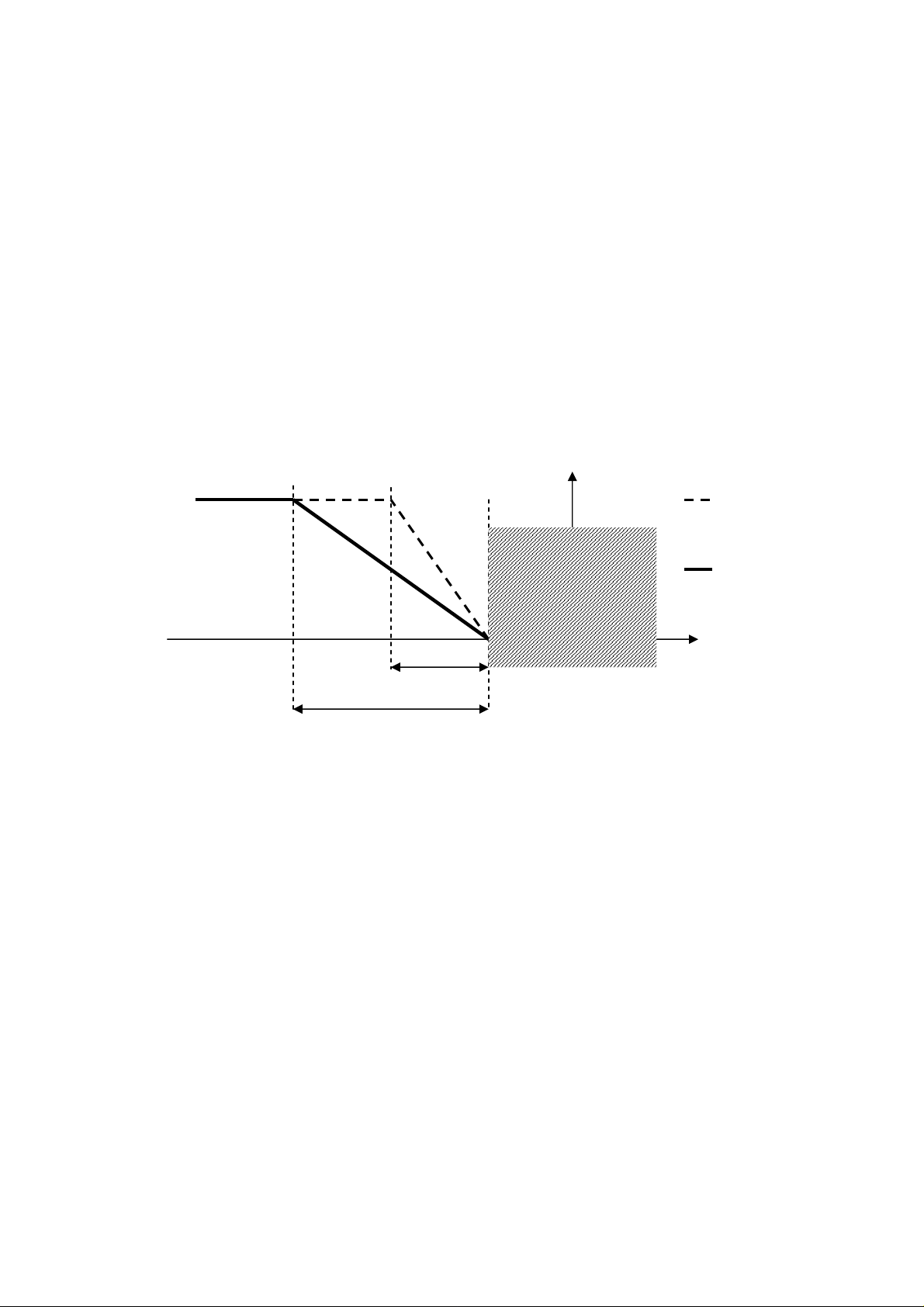
C-PRO KILO AHU APPLICATION MANUAL
SetPoint
- Delivery
Pb01
Pb01 x 2
6.8 Post-Heating
This may be performed using one coil (PG01=3) or, alternatively, utilizing electrical
resistances (PG14>0). The post-heating serves two main purposes: integration of heat in
heating or compensation in the dehumidification phase in order to realize the amount of heat
lost (i.e. drop in temperature) during dehumidification.
The regulation takes place on the running delivery SetPoint and the valve can be commanded
using a proportional algorithm (P), or proportional integral (PI). The referenced probe is that
of the delivery temperature.
6.8.1 Post-Heating with coil
The third coil is used to regulate the post-heating valve in analogue mode, the regulation
utilizes twice the heating differential (Pb01).
The activation graph is as follows.
100 %
0 %
Neutral
Zone
Note. It is necessary to set the position of the analogue output of the valve operating on
parameter HA06. If HA06=0 the indicator will not be enabled on any of the analogue outputs.
Using this coil represents an alternative to using the electrical resistances.
Coil for Heating
Coil for
Post-Heating
T. Delivery
6.8.2 Post-Heating with resistance
Based on the number of configured resistances (PG14=1,2,3) double the regulation
differential (Pb01) must be divided proportionally in order to guarantee uniform startup of
each single stage of resistance. In addition to the number of resistances it is also necessary to
configure the positions of the relative configured digital outputs (parameters HE01, HE02,
HE03).
Pag. 60
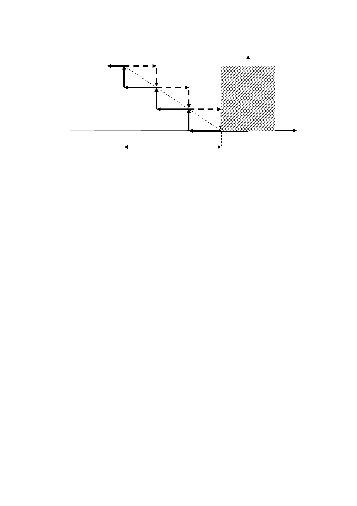
C-PRO KILO AHU APPLICATION MANUAL
1°
resistance
Pb01 x 2
2° resistance
3
° resist
ance
SetPoint
- Delivery
T. Delivery
Neutral
Zone
Within each insertion/removal of resistances a certain amount of time (parameter Pb20) must
elapse in order to avoid simultaneous occurrences. Using the Hd13 parameter it is possible to
enable the thermal alarm of the resistance, which provides for the immediate shutdown of the
device.
Note. In order to exclusively utilize the resistances for purposes of post-heating it is
important to set PG14>0 and PG01=2.
6.8.3 Status of the resistance
Each of the three stages of the resistances can assume one of the following operating states:
1. Disabled: the stage of the resistances is not managed by the controller. The symbol
“…” will appear in the user interface while in this state.
2. Off: the stage of the resistances is off. The word “OFF” will appear in the user
interface while in this state.
3. Waiting for startup: the stage of the resistances is about to startup, and is in queue for
a protection timetable. In this state in the user interface you will see written (and
flashing) “WON”.
4. Waiting for shutdown: the stage of the resistances is about to shutdown, and is in
queue for a protection timetable. In this state in the user interface you will see written
(and flashing) “WOF”.
5. On: the stage of the resistances is on. In this state in the user interface you will see
written “ON”.
6. Alarm: the resistances are blocked as a result of the relative thermal alarms. In this
state in the user interface you will see written “ALL”.
Pag. 61

C-PRO KILO AHU APPLICATION MANUAL
PU01: Set Point
PU03
6.9 Dehumidification
In order to adjust the comfort of the ambient it is necessary to also consider the humidity in
the air and regulate it based on a determined desired Set Point percentage (PU01) and at a
neutral zone (PU02) in which the humidity conditions are acceptable and do not require any
intervention. The regulation of the dehumidification is proportional-integral, to render it only
proportional you need to only set the integral time to zero (PU04=0).
If the ambient humidity probe is present it is possible to command a dehumidification process
by utilizing the cooling coil in order to eliminate the humidity from the incoming air.
Dehumidification management is enabled by activating parameter PG12=1, in the
constructor menu.
6.9.1 Dehumidification regulation
The regulation utilizes the same cooling coil, thus implying that there are at least two
configured coils (PG01>1). The ambient air humidity probe is also enabled (PH41=1), if the
probe is disabled or in error the management of dehumidification is inhibited. It is also
necessary to configure the positions of the analogue outputs for the valve of the cooling coil
(HA05). Since the same coil is used for the cooling the regulation of dehumidification
assumes the following rules:
1) When requesting only cooling the coil is regulated according to the logic previously seen.
2) When requesting only to dehumidify the coil is utilized exclusively to dehumidify the
ambient air and is illustrated in the following graph:
100 %
Neutral
Zone
0 %
U. Ambient %
3) In case where the requested actions are mixed and require both dehumidification and
cooling you will need to consider the average value of the two requests and the coil will be
commanded with the arithmetic mean of the two values.
6.9.2 Regulation limit on dehumidification
When there is an active request for dehumidification and there is a pending request for
continuous heating, this function (enabled by parameter PU05=1) allows for limiting the
Pag. 62

C-PRO KILO AHU APPLICATION MANUAL
SetPoint
- Delivery
Pb01
Pb01 x 2
cooling valve opening to dehumidify in order to contrast the continous decrease in
temperature (required by the dehumidification) and rapidly returning to the desired conditions
in temperature. This action has a more immediate effect on temperature and allows for
energy savings, optimizing coil control.
No
limitation
100 %
Maximum
limitation
0 %
Neutral
Zone
T. Delivery
Heating coil
Post-Heating coil
Limited action on cooling
coil for dehumidification
When the dehumidification request is active the action limit’s objective will be to limit the
dehumidificatin in order to prevent continuously cooling the air (caused by dehumidification)
and, as a result, to always request more heat to the heating (and post-heating) coils. This
action optimizes the regulation resulting also in energy savings.
Note. If the delivery air temperature probe is in error this regulation cannot be utilized.
Example 1
Dehumidification request = 80%
Dehumidification limitation = 50%
In this condition the request for dehumidification to the coils will either be 40% or 50% of
the 80% of the effective request.
Example 2
Dehumidification request = 80%
Dehumidification limitation = 25%
In this condition the request for dehumidification to the coils will either be 60% or 25% of
the 80% of the effective request.
Example 3
Dehumidification request = 80%
Dehumidification limitation = 0%
In this condition the request for dehumidification will pass entirely to the coil.
6.10 Humidification
To adjust the comfort of the ambient it is necessary to also consider the humidity in the air
and to regulate it based on a determined Set Point desired percentage (PU01) and at a neutral
Pag. 63

C-PRO KILO AHU APPLICATION MANUAL
PU11: Set Point
OFF
T. Delivery
PU12: Diff.
ON
PU01: Set Point
OFF
PU03: Di
ff.
ON
zone (PU02). If the ambient humidity probe is present it is possible to command the
humidifier using On/Off switch or by using the module. Humidity management is enabled by
activating the parameter PG06>0, in the constructor menu. The ambient air humidity probe is
also activated (PH41=1), if the probe is disabled or in error dehumidification management
will be inhibited.
It is possible to activate a digital input for the dehumidifier alarm by setting the position using
the parameter Hd15. With Hd15=0 the alarm is disabled.
6.10.1 Enabling humidifier (delivery temperature
operation)
In order to function correctly the humidifier requires a minimum value for air temperature,
for which it identifies a Set Point (PU11) and relative hysteresis (PU12) on the delivery
temperature to enable/disable the humidifier. This function is enabled by parameter PU10. In
case PU10=0 (function disabled) the humidifier will startup/shutdown on the normal Set
Point percentage (PU01).
With the delivery probe in error the function is inhibited and the humidifier will
startup/shutdown on the Set Point percentage.
6.10.2 Humidifier On/Off
In order to utilize the On/Off regulation of the humidifier you must set parameter PG06 to 1.
It is necessary to also set the position of the digital output in which will be connected to the
humidifier (parameter HU01).
Neutral
Zone
U.Ambient %
Note. In order to utilize this function it is necessary to enable the ambient humidity probe,
setting parameter PH41 to 1. When the probe is in error the humidifier is shut off.
Pag. 64

C-PRO KILO AHU APPLICATION MANUAL
PU01: Set Point
0%
UR% ambient
PU03: Diff.
100%
6.10.3 Modulating humidifier
In order to utilize the modulating regulation of the humidifier it is necessary to set the
parameter PG06 to 2. The position of the analogue output that is connected to the humidifier
also needs to be set (parameter HA08).
Neutral
Zone
Note. To utilize this function it is necessary to enable the ambient humidity probe by setting
parameter PH41 to 1. When the probe is in error the humidifier is shut off.
6.10.4 Humidifier status
The humidifier assumes the following operating states:
1. Disabled: the humidifier has not been configured for the system. While in this state
you will see the symbol “…” in the user interface.
2. Off: humidifier is off. While in this state you will see written “OFF” in the user
interface.
3. Off due to delivery temperature: humidifier is off due to the low delivery air
temperature. While in this state you will see written “OFFt” in the user interface.
4. On: humidifier is on. While in this state you will see written “ON” in the user
interface.
5. Alarm: humidifier is in alarm. While in this state you will see written “ALL” in the
user interface.
Pag. 65

C-PRO KILO AHU APPLICATION MANUAL
6.11 External Air Shutters
The program provides the managment of a motorized shutter for the intake of external air to
support the ambient temperature regulation. The type of management is determined by
parameter PG07, in the constructor menu:
- PG07=0: Disabled
- PG07=1: Enabled in modulating regulation
- PG07=2: Enabled in fixed opening
In modulating regulation, the shutter can be utilized for:
- Free-Cooling / Free-Heating in temperature (parameter PS01=1)
- Free-Cooling / Free-Heating heat exchanger (parameter PS01=2)
- Air quality control (parameter PS02=1)
The regulation also provides a position of minimal opening of the shutter to guarantee the
minimal quantity of projected renewed air (parameter PS05) and the corresponding
maximum position of the opening (parameter PS06).
6.11.1 Regulation in fixed opening
In this mode the external air shutter always assumes the same value of opening as decided by
parameter PS10. In this regulation the range of values of opening is from 0% to 100%, there
is no minium value for the opening. In order to utilize this regulation it is necessary to set
PG07=1.
Note. With this modality the free-cooling, free-heating and the air quality control cannot be
utilized.
6.11.2 Enable Free-Cooling and Free-Heating in temperature
The free-cooling in temperature, if enabled (PS01=1), can be activated when the difference
between the ambient air temperature and the external air temperature reaches the Set Point
which has been set (parameter PS13) and relative hysteresis (parameter PS12).
The free-heating in temperature, if enabled (PS01=1), can be activated when the difference
between the external air temperature and the ambient air temperature reaches the Set Point
which has been set (parameter PS13) and relative hysteresis (parameter PS12).
Pag. 66

C-PRO KILO AHU APPLICATION MANUAL
PS12: Diff.
T. Ambient
–
T. External
T. Ex
ternal
–
T. Ambient
PS12: Diff.
PS15
HAmb
–
HExt
HExt
–
HAmb
PS15
Enable Free-Cooling in temperature Enable Free-Heating in temperature
PS13: SetFC
PS13: SetFH
Note. It is necessary to enable the utilization of the external air temperature probe (PH40=1).
If the probe is in error the regulation is disabled.
6.11.3 Enable Free-Cooling and Free-Heating heat exchanger
The heat content regulation also considers the air humidity to enable the free-cooling and
free-heating processes. In order to utilize this function you must set PS01=2 and it is
necessary to enable the ambient humidity probes (PH41=1), external temperature (PH40=1)
and external air humidity (PH47=1). Additionally, it is necessary to set the value of the
atmospheric pressure in hPa (parameter PH34). The regulation provides the calculation of the
external heat content (HExt) and ambient heat content (HAmb).
The calculation of the heat content is done using the temperature value and the humidity
value utilizing the atmospheric pressure to achieve a more precise calculation. The
differential Set Point (PS16) and relative hysteresis (PS15) must be set in order to enable at
the regulation.
To enable see graphs below:
Enable Free-Cooling heat exchanger Enable Free-Heating heat exchanger
PS16: SetFCHeat
PS16: SetFHHeat
Note. If one of the probes in use are in error or if the regulation has not been configured it
will be disabled. This regulation can be used only in the presence of a external air humidity
probe which has been configured on the expansion; therefore this function can be utilized
only if the expansion is enabled (PG02=1).
Pag. 67
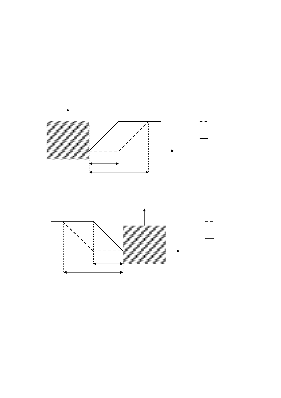
C-PRO KILO AHU APPLICATION MANUAL
T. Delivery
Pb01
Pb01 / 2
100 %
0 %
T. Delivery
Pb01
Pb01 / 2
100 %
0 %
6.11.4 Free-Cooling and Free-Heating Regulation
The regulation of the free-cooling/free-heating commands the opening of the external air
shutter. When free-cooling/free-heating conditions exist; or if the regulation can be enabled
(and the request is greater than zero) the ramps which command the heating/cooling are split
into two successive ramps, the first (half the differential) regulates the free-cooling/freeheating using the external air shutter, the second regulates the heating/cooling valves.
SUMMER operation/COOLING: Free-Cooling
Set Point
Delivery
Cooling coil
Neutral
Zone
WINTER operation/HEATING: Free-Heating
Set Point
Delivery
Neutral
Zone
External air shutter
regulated in free-cooling
Heating coil
External air shutter
regulated in free-heating
Note. If one of the probes included in the regulation is in error the regulation of the freecooling/free-heating can no longer be utilized and the heating/cooling ramp regulate the total
regulation differential.
Pag. 68

C-PRO KILO AHU APPLICATION MANUAL
6.11.5 Air quality control
The external air shutter may be used to replace the air upon request by the appropriate probe
(VOC/CO2). It is necessary to enable the parameter PS02=1, and the regulation probe for the
air quality (PH46>0). The external air shutter can be commanded based on the regulation
probe at set point (PS20) and at the relative differential (PS21).
Note. If the air quality probe is in error the regulation is inhibited. The probe can be one of
two types: 4..20mA (PH46=1) or 0..5V (PH46=2);
6.11.6 Shutter Command
The external air shutter can be utilized for two regulations: free-cooling/free-heating and air
quality control. The priority of these requests is decided by parameter PS03:
- PS03=0: The shutter is commanded by Free-cooling / Free-heating
- PS03=1: The shutter is commanded by air quality control
- PS03=2: The shutter is commanded by the largest request
- PS03=3: The request of the shutter is calculated as the arithmetic mean of the two
requests for free-cooling (/free-heating) and air quality control in order to fulfill both
active requests.
The shutters are managed through two digital outputs which are configurable by parameters
HS01 and HS02 which command the opening and closing, respectively. In order to correctly
command the external shutter motor it is necessary to set the following parameters:
- PS05. Minimum value of shutter opening.
- PS06. Maximum value of shutter opening.
- PS07. Shutter run time to go from 0% to 100%.
- PS08. Maximum time to maintain signal at end of relay.
- PS09 (optional). If greater than zero the command at relay are given only when the
actual variation on the regulation ramp exceeds the set value. If PS09=0 the
command will always pass.
Note. Each time the unit is in ON status (for turning on the card, for restoration of an alarm
block, or to restore the feed after a black-out), the external air shutters will re-align; for the
entire run time (plus eventual time PS09), the shutter will close and the regulation will be
interrupted. Once the run time has elapsed the regulation will return to its normal operating
state. This is necessary because there is no feedback for controlling the position of the
shutter.
Pag. 69

C-PRO KILO AHU APPLICATION MANUAL
6.11.7 Shutter status
In the user interface you can identify the operating status of the shutters which will present
you with one of the following:
1. Disabled: the shutter is not managed by the controller. In the user interface you will
see the symbol “ - ” when in this state.
2. Closed: the shutter is closed. In the user interface you will see
written“CHIUSA”(CLOSED) and a value of 0.0%. when in this state
3. Opening: the shutter is in the process of opening. In the user interface you will see
written “APERTURA” (OPENING) flashing with the corresponding value when in
this state.
4. Open: the shutter is open and still at the determined value. In the user interface you
will see written “APERTA”, (OPEN) and the corresponding value of opening when in
this state.
5. Closing: the shutter is in the process of closing. In the user interface you will see
written “CHIUSURA” (CLOSING) flashing with the corresponding value when in this
state.
6. Alignment: the shutter is in the process of moving in order to align in response to the
start up of the unit or because the tension is restoring. In the user interface you will
see written “ALLINEAM.” (ALIGNMENT) with the value 0.0% flashing.
Pag. 70

C-PRO KILO AHU APPLICATION MANUAL
Pr03: Set Point
OFF
Pr04: Diff.
ON
OFF
ON
OFF
ON
Pr05 Pr05
6.12 Heat Recuperators
When the quantity of renewed air is substantive the air treatment centers provide a system
which recovers the expulsion air for a better exercise of energy costs. Using the parameter
(PG13>0) it is possibile to utilize the heat recovery by selecting one of the following
different recuperators:
- PG13 = 0: Management disabled
- PG13 = 1: Recuperator at cross flow
- PG13 = 2: Recuperator at double coil
- PG13 = 3: Recuperator rotating On/Off
- PG13 = 4: Recuperator rotating modulating
Recovery management presupposes that the expulsion air temperature probe is present,
therefore in order to utilize the recovery the probe will need to be enabled by setting
parameter PH42=1.
6.12.1 Recuperators at cross flow
In order to utilize this recuperator set PG13=1. The recuperator provides a by-pass shutter
which is used to prevent the passage of external air through the air exchange channels. The
recuperator is normally always active and is by-passed during the free-cooling/free-heating
phases or during the defrost cycles with external temperatures that are too low. Set the
setPoint (Pr03) and the relative differential (Pr04) in order to activate the defrost cycle.
T. Expulsion
When the minimum temperature conditions of the expulsion air are reached, as represented in
the diagram, a cyclical sequence of recuperator by-pass are activated in order to permit the
expulsion air (hot, ambient air) to defrost the air exchange channels.
Minimum expulsion temperature
Shutter By-Pass
Pag. 71
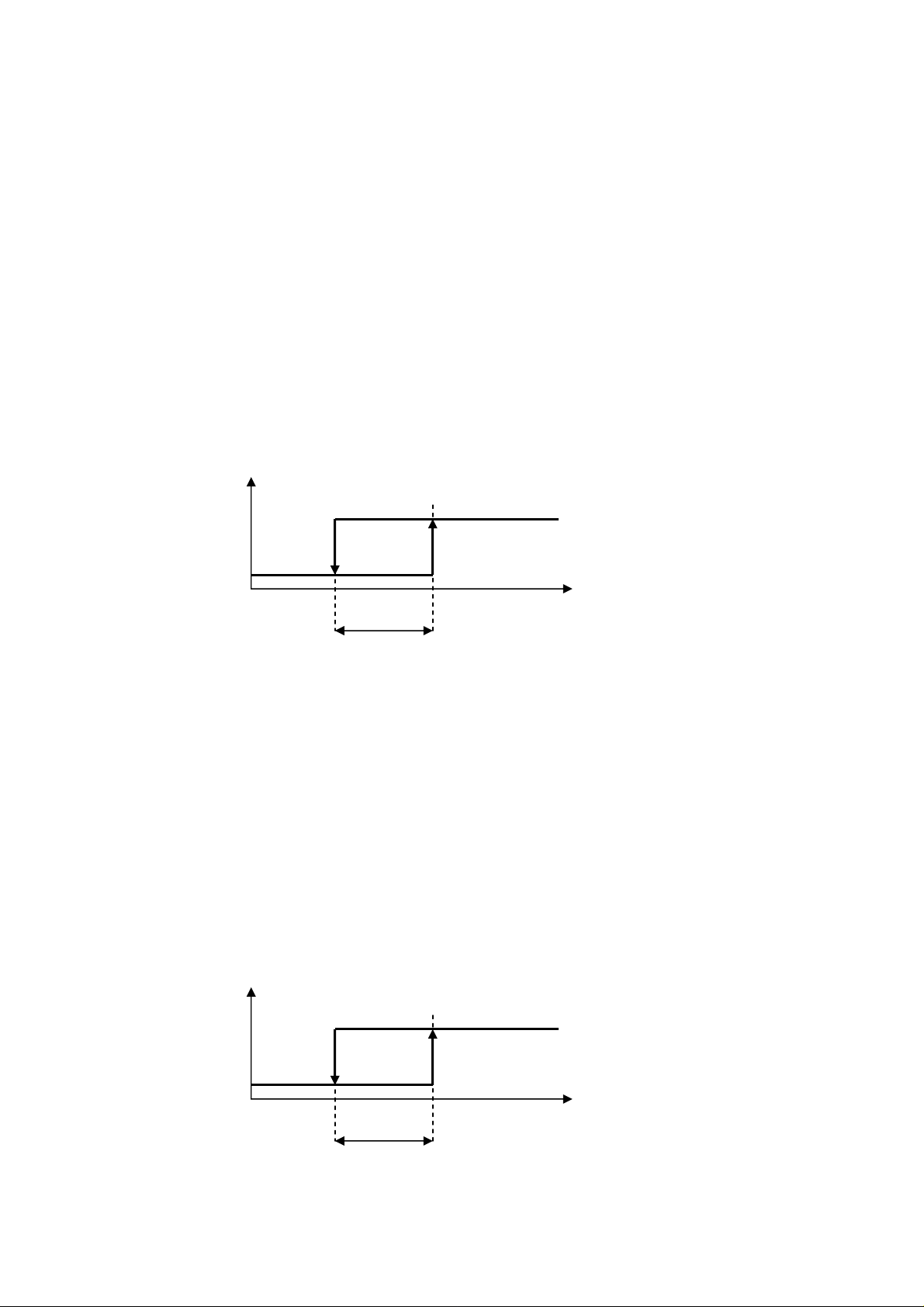
C-PRO KILO AHU APPLICATION MANUAL
Pr01: Set Point Recuperator
OFF
Pr02: Diff.
ON
Pr01: Set Point Recuperator
OFF
Pr02: Diff.
ON
After the delay Pr05 the by-pass shutter will activate in oder to allow for defrosting. When
the temperature rises above the allowable value the shutter will deactivate while the
recuperator restarts.
Note. It is necessary to set the position of the digital output of the recuperators by-pass
shutter using the parameter dedicated to the recuperator, Hr01. When the regulation probes
are in error this function is disabled.
6.12.2 Recuperator at double coil
In order to utilize this recuperator set PG13=2. The recuperator at double coil is activated
using the circulation pump (of fluid exchange) between the two coils. In order to limit the
pumps energy consumption, the activation will be managed by the difference between the
expulsion air temperature and external air temperature (parameter Pr01 and relative
differential Pr02). The circulation pump will stop during the free-cooling and free-heating
phases.
| T.Expulsion – T.External |
This recuperator does not require its minimum expulsion temperature to be regulated since
frost will not accumulate inside the coil.
Note. It is necessary to set the position of the digital output of the recuperator, using the
dedicated parameter, Hr01. The external temperature probe must also be enabled
(PH40=1). When the regulation probes are in error this function is disabled.
6.12.3 Rotating Recuperator
In this case the recuperator can be regulated in two different ways: On/Off (PG13=3), or
with an analogue output (PG13=4) and is only active when the fans are turned on.
The recuperator will be deactivated during the free-cooling and free-heating phases.
PG13=3. Regulation On/Off
| T.Expulsion – T.External |
Pag. 72
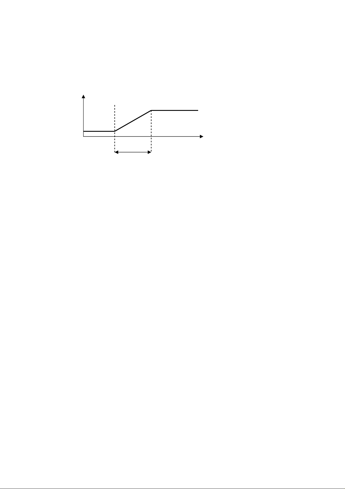
C-PRO KILO AHU APPLICATION MANUAL
Pr01: Set Point Recuperator
0 %
Pr02: Diff.
Note. It is necessary to set the position of the digital output of the recuperator, using the
dedicated parameter, Hr01. The external temperature probe must also be enabled
(PH40=1). When the regulation probes are in error this function is disabled.
PG13=4. Modulating regulation
| T.Expulsion – T.External |
Note. It is necessary to set the position of the digital output of the recuperator, using the
dedicated parameter, Hr09. The external temperature probe must also be enabled (PH40=1).
When the regulation probes are in error the function is disabled.
6.12.4 Recuperator status
The recuperator may assume one of the following modes of operation:
1. Disabled: the recuperation is not being managed. In this state in the user interface you
will see the symbol “…”.
2. Off: the recuperator is off. In this state in the user interface you will see written
“OFF”.
3. Defrosting: the recuperator is off and defrosting is activated (only when recuperator is
at cross flow, PG13=1). In this state in the user interface you will see written (and
flashing) “OFF_D”.
4. Off for free-cooling/heating: the recuperator is off (because of a request for free-
cooling/heating). In this state in the user interface you will see written “OFF_F”.
5. On: the recuperator is on. In this state in the user interface you will see written “ON”.
Pag. 73
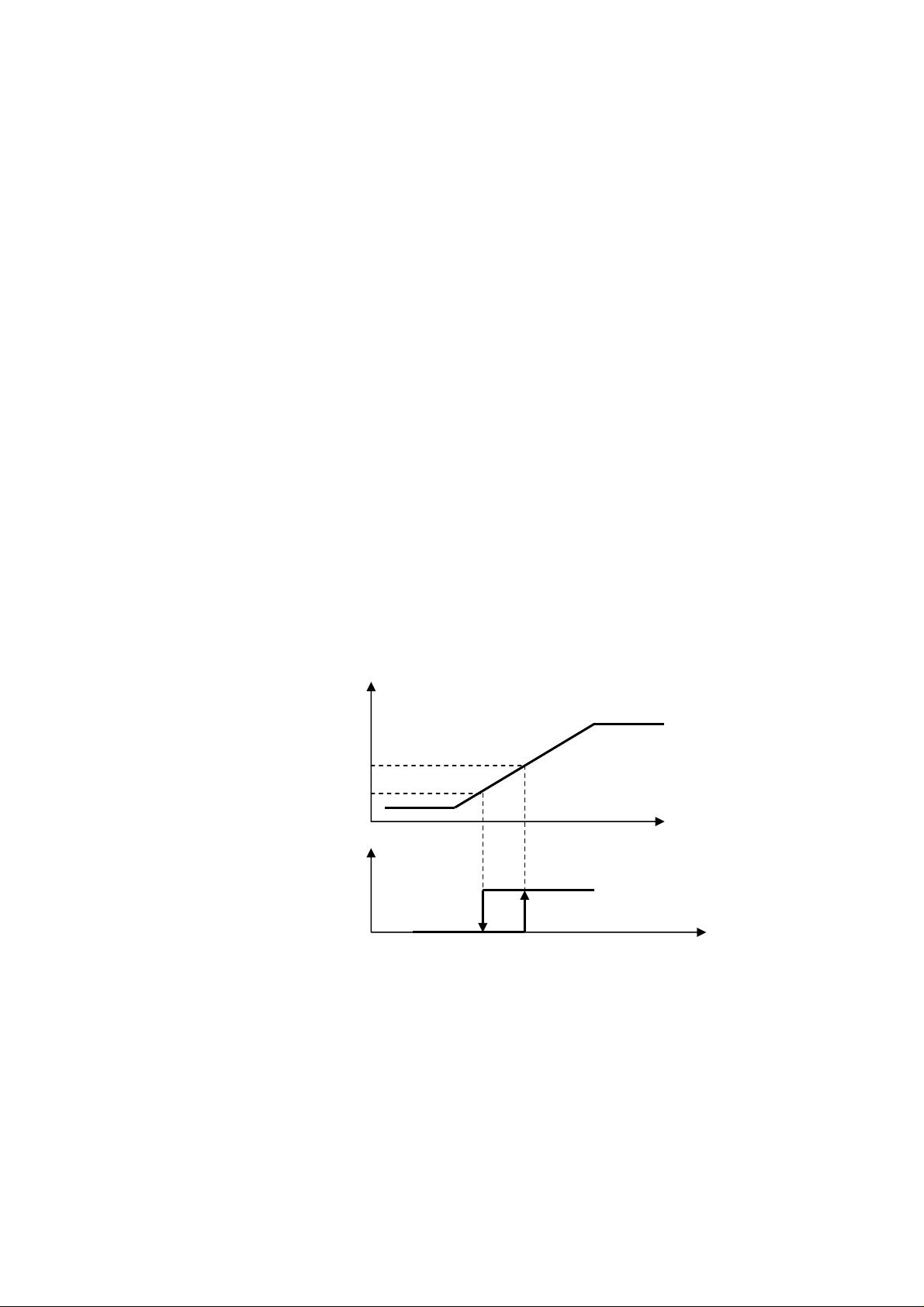
C-PRO KILO AHU APPLICATION MANUAL
PP02: Set % Pump ON
PP03: Set % Pump OFF
Ramp %
Pump
ON
OFF
6.13 Heating/Cooling Pumps
A simple method for managing the two circulation pumps (for heating/cooling) is provided.
In order to enable the cooling pump you need to set paramater PG10 to 1. To enable the
heating pump you will need to set parameter PG11 to 1 in the Consructor menu.
Based on the requirement you may choose between two regulations by going to parameter
PP01 (continuous regulation, On/Off regulation).
It is possible to activate the digital input for the thermal alarm for either of the two pumps by
setting the positions using parameters Hd10 and Hd11. With Hd10=0 or Hd11=0 the relative
alarm is not enabled.
The positions of the dedicated digital outputs also need to be set using the parameters HP01
and HP02. If the respective parameter is equal to zero none of the digital outputs will
command the device.
6.13.1 Continuous regulation
The continuous regulation is dependent on the status of the central unit. The pumps will
startup and shutdown each time the machine starts up and shuts down. In order to set this
regulation select PP01=0.
6.13.2 Regulation On/Off
The circulation pumps will activate when there is an actual heating/cooling request which
exceeds a startup set (PP02) and they shutdown when the same request falls below a certain
shutdown set (PP03). In order to set this regulation select PP01=1.
Regulation ramp
When the regulation ramp exceeds PP02 the pump will activate; when it falls below PP03 a
timer will activate keeping the pump active for a set period of time (parameter PP04). The
timer resets if the ramp returns above PP02. The pump will be shut down by using the
shutdown command from the unit cancelling the active timer.
Note. In case where the primary regulation is on the fans (PG04=0), this regulation can be
used only if the fan regulation is in the modulating type.
Pag. 74

C-PRO KILO AHU APPLICATION MANUAL
6.13.3 Pump status
Both pumps may assume any of the following operating states:
7. Disabled: the pump is not managed by the controller. In the user interface you will
see the symbol “ - ” when in this state.
8. Off: the pump is off. In the user interface you will see written “OFF” when in this
state.
9. Waiting for shutdown: the pump is in the process of shutting down, and is in queue for
scheduled protection. In the user interface you will see written (and flashing)
“WOFF” when in this state.
10. On: the pump is on. In the user interface you will see written “ON” when in this state.
11. Alarm: the pump alarms are on. In the user interface you will see written “ALL” when
in this state.
6.13.4 Security Inputs
Thermal pump security management is provided for both configured pumps. To enable the
alarm you must go into the constructor menu and set the positions which will be connected to
the digital inputs in order to survey the security (Hd10, Hd11). In order to not activate the
security and related alarm you need to set the parameter of the position to a 0 value.
Pag. 75

C-PRO KILO AHU APPLICATION MANUAL
6.14 Unit at single coil (seasonal)
In this type of unit (PG01=1) there is only one dedicated valve for heating and cooling and, if
enabled, there is a single circulation pump; the operating mode (parameter MOdE)
determines which behavior to utilize. In the same way all the regulations (fans, freecooling/free-heating, regulations of set-point, alarms, etc..) are distinguished based on the
operating mode. The heating function is guaranteed when the parameter MOdE=1;
meanwhile the cooling function is guaranteed when MOdE=0.
The correct software configuration is obtained considering all the resources (parameters and
operating states) normally utilized for heating the machine when using more than one coil,
which, in these particular centers, are considered mixed resources commanded univocally
based on operating mode (summer/winter). The “mixed” hardware parameters to consider
for the unit at single coil with circulation pump are the following:
PG01=1 (single coil)
PG10: enable circulation pump (heating)
HP01: position of circulation pump digital output (heating)
Hd10: position of circulation pump alarm (heating)
HA04: position of heating/cooling valve analogue output (heating)
For units using a single coil it is not possible to manage dehumidification and postheating. The resources normally managed for cooling and post-heating are not piloted; it is
therefore recommended to reset all the configuration parameters in order to avoid
malfunctions.
16.14.1 Primary regulation
For these types of units it makes sense to also set the primary regulation parameter PG04;
using the appropriate constructor parameter, PG04, it is possible to choose the organ on
which the primary regulation will be made from the central unit: fans or valves.
- If PG04 = 0, the primary regulation is made on the fans which, at the appropriate
time, will be regulated in different ways (parameter PF01). This type of configuration
excludes utilization of the valve and therefore the controller does not provide any
commands on the analogue/digital outputs for controlling the single heating/cooling
valve.
- If PG04=1, the primary regulation is made on the valve. The intake of hot/cold air is
modulated by the heating/cooling coil, meanwhile the fans are working to recirculate
the air of the central unit. Fan regulation can be set with the appropriate parameter
PF01. In this configuration it is necessary to determine the position of the analogue
output which will be connected to the single valve of regulation.
In units with more than one coil the parameter PG04 does not condition any regulation.
Pag. 76
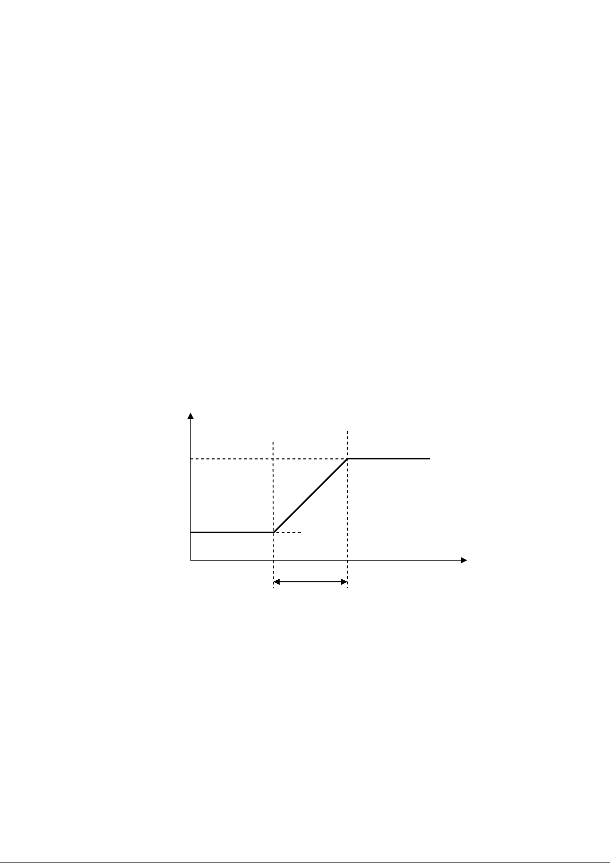
C-PRO KILO AHU APPLICATION MANUAL
PC02: Set maximum
SEtC: Set Point
T. External
PC04: Diff.
6.15 Management (various)
6.15.1 Single or distinct Set Point
It is possible to manage a single regulation Set Point for summer/winter, or to set two
different ones. If the parameter PH27 Enables the single/distinct Set Point is set to 1 the Set
Point is singular (only one parameter), otherwise the Set Point is distinct (two distinct
parameters: SEtH and SEtC).
In the case of a single Set Point (PH27= 1) the parameter SEtC (summer Set Point), is no
longer valid and the single regulation Set Point becomes the SEtH which no longer assumes
the value of a single winter set but instead that of a single regulation Set Point for the
summer/winter.
6.15.2 Compensation for Set Point
Only during summer operating mode (parameter MOdE=0=CooL), the cooling regulation
requests a compensation for the regulation ambient temperature Set Point to function with the
external temperature (parameter PC01 to enable the function). The function is important to
avoid an accessive jump in thermal temperature between the external and internal ambient
temperatures and ensures adequate comfort under mutual conditions. Furthermore, this
allows for energy savings on the implant.
Ambient
Set Point
PC03: Set initial
compensation
The compensation Set Point increases proportionally with the increase in external
temperature until it reaches the maximum admissible set configured at parameter PC02.
Note. To utilize this function it is necessary to enable the external temperature probe and set
the parameter PH40 to 1. When the external probe is in error this function is inhibited.
6.15.3 Variation Set Point from Digital inputs
The program provides the possibility to manage a parameter OS01 Offset Set Point from DI
which, based on the status of the Digital inputs, provides a sum at the regulation Set Point. It
Pag. 77

C-PRO KILO AHU APPLICATION MANUAL
is possible to set the logic for the Digital inputs by setting the parameter PH50: 0=NO
(Normally open), 1=NC (Normally closed).
In order to enable this function you will need to enable parameter PH25 Enable variation Set
Point from Digital inputs and set the position on which the related Digital inputs will be
connected (parameter Hd03). If this parameter is set to 0, the function is disabled.
Note. The offset is summed at its current value of the Set Point and not by the value which is
defined by the parameter; this indicates that the Set Point could have already been modified
due to other interventions: time zone, variations by supervisor.
6.15.4 Variation Set Point from Supervisor
The program provides the possibility to manage a parameter OS02 Offset Set Point from
Supervisor which, based on the status set by the supervisor, sums an offset at the regulation
Set Point. To enable this function set the parameter PH26 Enable variation Set Point from
supervisor and set to one the related variable from supervisor.
Note. The offset is summed at the current value of the Set Point and not that which is defined
by the parameter; this indicates that the Set Point could have already been modified due to
other interventions: time zone, variations by Digital inputs.
6.15.5 Variation Set Point in nocturnal time zone
The program provides the possibility to manage the nocturnal time zone in order to modify
the value of the regulation Set Point of the temperature. In the daytime zone the Set Point
remains that of regulation, meanwhile during the nocturnal time zone it is possible to sum an
offset (parameter PT03). The nocturnal zone is defined by two paramaters: begin time zone
(PT01) and end time zone (PT02). To enable the function activate the parameter PH28
Enable nocturnal time zone for modification of regulation Set Point.
If the RTC is in alarm or disabled, the function becomes inhibited.
Note. The offset is summed at the current value of the Set Point and not that which is defined
by the parameter; this indicates that the Set Point could have already been modified due to
other interventions: variations by Digital inputs, supervisor.
6.15.6 Manual fan operation
In this state the devices do not participate in thermoregulation; they are however sensitive to
eventual alarms. Manual operation (or operating less than the two delivery and pickup fans)
is guaranteed by parameter\ PM20.
⋅ If value set to 0 (Auto) this will define normal device behavior
⋅ If value set to 1 (Manu) this will disable the fans and bring them to manual operation
Fans operating manually do not participate in regulations and can be forced into operation
using parameter PM21.
If the fans are the On/Off type they may be forced on by simply setting any value greater than
0.0% at parameter PM21.
If the fans are in modulating regulation, and therefore at inverter with parameter PM21, it is
possible to set the speed which must be maintained during the test phase. In each case where
the value is 0.0% the fans will remain off.
While operating manually the fans will always be sensitive to alarms and related
consequences. In order to restore at the regulation you will need to reset parameter PM20 to
the value “Auto” (Automatic).
Pag. 78

C-PRO KILO AHU APPLICATION MANUAL
6.15.7 Last date of maintenance
In the Menu Manutentore->Funzionamento (Maintenance Operator->Operation) you will
find a page with the ability to memorize the last date of maintenance for the implant. By
pressing on “Aggiorna” (Update) the old date which is in the system will automatically be
updated with the new correct date; updating the maintenance date can be done at parameter
PM90.
6.15.8 Restoring default parameters
Using the procedure “Ripristino parametri”(Restore Parameters) it is possibile to restore all
the parameters of the implant to their default values. Enter the installation operator Menu-
>Default (accessible only when the machine is shut off) and set the parameter PH15=SI (1)
“YES (1)” and wait until the value “NO” (0) appears on the display. The system will
automatically restore all of the parameters.
After this operation is complete it is necessary to unfeed and refeed the machine in order to
avoid malfunctions.
6.15.9 Programming key
It is possible to save the values of all the parameters for the implant in the program key with
the capability of transferring a copy onto one or more compatible instruments. You may
only save and restore when the machine is turned OFF (OFF_D or OFF_S) connecting the
key to the programming connector.
To save a particular parameter map onto the key:
- Enter the DEFAULT Menu
- Press the SET (ENTER) key on OK near the voice
EVKEY Store: the transfer of the parameters onto the key
is evidenced by the related flashing led light
- Wait for the flashing to stop: if the led is green, the
operation has concluded correctly, otherwise the light will
be red
To copy a parameter map from the key onto a compatible
device:
- Enter the DEFAULT Menu
- Press the SET (ENTER) key on OK near the voice
EVKEY Restore the transfer of the paramaters from the
key onto the compatible device, this is evidenced by the
related flashing led light
- Wait for the flashing to stop: if the led is green, the
operation has concluded correctly, otherwise the light will
be red
Note. The data saved onto the key includes information on the product and related version
and methods for transferring parameter maps onto other compatible devices.
Pag. 79

C-PRO KILO AHU APPLICATION MANUAL
7 DIAGNOSTICS
The application is in the process of managing a series of alarms and related fans, pumps,
probes and other operations from the central unit. Based on the various types of alarms it is
possible to configure a rearmament (if manual or automatic), an eventual delay in signal and
of other actions which will follow in a specific case.
When one or more alarms are active the alarm icon flashes.
To see the alarms, choose ALARMI (ALARMS) from the general Menu; alternatively, alarms
can be seen at the Main page by pressing ESC and then choosing “Mostra ALARMI
>>”(Show Alarms>>).
If from one alarm page you press the ESC key, or if you wait for the 60 second timeout
period, you will be brought back to the main application page.
In order to run the various active alarms you need to press the ENTER key further: the alarms
are presented in order of priority as they are presented in the alarm table.
All the digital inputs related to the alarms are managed from the parameter PH51 which
assumes the following significance:
⋅ If set to “NO” the inputs are normally open: logic N.O.
⋅ If set to “NC” the inputs are normally closed: logic N.C.
7.1 Manual and automatic alarms
As previously displayed there are two types of alarms, those which are re-armed manually
and those which are re-armed automatically. Certain alarms are capable of having their type
of rearmament set from the parameter (Riarmo alarmi) “R-arm alarm” more in accordance
with user requirements. Meanwhile other alarms already have their rearmament stabilized by
the application.
7.1.1 Manual alarms
In the case where a manually re-armed alarm is present, the led L0 will begin flashing.
Once the conditions for which the alarm are verified they will be restored allowing for
manual rearmament of the alarm. To perform this operation:
⋅ position on the alarm restore page
⋅ press the ENTER key for approximately 2 seconds.
At this point if there are no other alarms, the following will appear on the indicated page “NO
ALARMI”(NO ALARMS), the led L0 will shut off and the machine will return to normal
operation or you will view the page relating to the next active alarm.
The consequences derived from a manual active alarm remain valid until the user cancels the
alarm message.
7.1.2 Automatic alarms
In the case where a automatically re-armed alarm is present, the led L0 will begin flashing.
Once the conditions for which the alarm are verified the rearmament and the cancellation of
the alarm message are restored; restoration is automatic without user intervention. The
consequences derived from an automatic active alarm remain valid until the causes for which
the alarm went off are restored.
Pag. 80

C-PRO KILO AHU APPLICATION MANUAL
7.2 Table of Alarms
The following is a list of all the alarms managed by the application. The order of
presentation is the same as the order of presentation for the active alarms. All alarms can be
viewed even when the mahcine is off.
Code Description of alarm Re-arm
AL01 Thermal delivery fan (*²) Auto
AL02 Thermal pickup fan (*²) Auto
AL03 Alarm inverter delivery fan (*²) Auto
AL04 Alarm inverter pickup fan (*²) Auto
AL05 Thermal circulation pump Auto
AL08 Air filter pressure switch A/M
AL09 Humidifier A/M
AL10 Airflow meter (*²) Manu Shuts down all devices May be set
AL11 Anti-freeze Auto
AL13 Fire/smoke Alarm (*²) Auto Shuts down all devices
AL14 Operating hours – delivery fans Manu*¹ Visualization AL15 Hours of operation – Uptake fan Manu*¹ Visualization AL16 Hours of operation – Heating pump Manu*¹ Visualization AL17 Hours of operation – Cooling pump Manu*¹ Visualization -
AL18 Ambient air probe broken or disconnected Auto
AL19 Air delivery probe broken or disconnected Auto
AL20 External air probe broken or disconnected Auto
AL21
AL22
AL23
AL25
AL26
AL27
AL28 RTC Alarm broken or discharged A/M
AL29 Expansion alarm Auto Stops devices on expansion May be set
to zero.
Ambient humidity probe broken or
disconnected
Air delivery pressure probe broken or
disconnected
Anti-freeze temperature probe damaged or
disconnected
Pre-heating air temperature probe damaged
or disconnected
VOC probe (or CO2) damaged or
disconnected
External air humidity probe damaged or
disconnected
A/M: Automatic or Manual alarm (set from parameter)
(*¹) To re-arm alarms connected to the hours of operation you need only reset the hours on the device
(*²) These alarms cause the unit to shutdown bringing it to the status OFF from alarm
Auto
Auto
Auto
Auto
Auto
Auto
Shuts down all devices Fixed 2 sec.
Shuts down all devices
Shuts down all devices
Shuts down all devices
Stops the pump Fixed 2 sec.
Visualization May be set
Stops the humidifier May be set
Shuts down fans and closes the
shutter
Forces heating coil to 100%
Forces cooling coil to 0%
Inhibits the regulations upon
which the probe is dependent
Inhibits the regulations upon
which the probe is dependent
Inhibits the regulations upon
which the probe is dependent
Inhibits the regulations upon
which the probe is dependent
Inhibits the regulations upon
which the probe is dependent
Inhibits the regulations upon
which the probe is dependent
Inhibits the regulations upon
which the probe is dependent
Inhibits the regulations upon
which the probe is dependent
Inhibits the regulations upon
which the probe is dependent
Inibits management of the time
zone
Note. To activiate the alarms derived from the digital contacts you need to set to a value
greater than zero the relative position for which the dedicated digital inputs will be
connected. If the position is zero the alarm is not managed. A position may be repeated only
once; it is not possible to manage the same position like “OR” for additional alarms.
Consequence Delay
Fixed 2 sec.
Fixed 2 sec.
Fixed 2 sec.
May be set
-
May be set
May be set
May be set
May be set
May be set
May be set
May be set
May be set
May be set
-
Pag. 81

C-PRO KILO AHU APPLICATION MANUAL
PA38: Set Point
OFF
PA39 Diff.
ON
Anti-freeze probe alarm
7.2.1 Air Flow Meter Alarm
The flowmeter can be managed after the initial startup phase of the unit and after the Ritardo
flussostato da reset PA28 (Flowmeter delay from reset PA28): once this time elapses, if the
contact indicates lack of flow, the alarm will immediately go off.
During normal operation the flow sensor is continuously monitored: if the contact indicates
lack of flow for a period greater than that at parameter PA29 the alarm will immediately go
off.
Unit
ON
OFF
Flow
ON
Alarm
ON
PA28
PA29 PA29
The flowmeter alarm is restored manually, activation requires the shutdown of the unit
bringing it to the state of OFF da alarm (Alarm OFF).
7.2.2 Anti-freeze Alarm
The method used to enable the alarm is configurable with parameter PA35:
- PA35=0: alarm disabled
- PA35=1: alarm at digital input
- PA35=2: alarm at anti-freeze temperature probe (implies enabling the probe with
PH43=1)
T. anti-freeze air
Pag. 82

C-PRO KILO AHU APPLICATION MANUAL
7.3 Alarm relay
The program provides the possibility to manage a relay for a configurable alarm. For each
type of alarm there is a parameter that permits you to choose whether that particular alarm
must be signaled on the the alarm relay. Additional alarms can be addressed at relay.
The position of the digital output dedicated to signal the alarm can be set using the parameter
HA01, if equal to zero the alarm relay will not be utilized.
Using the relative parameter (PH60) it is possible to stabilize the polarity (NO, or NC) of the
digital output of the alarm.
7.4 Alarm history
The controller memorizes in a suitable (non volotile) memory zone organized like the FIFO
queue, the STORICO ALARMI (ALARM HISTORY), or rather it could be a list of the last
alarms verified.
In order to view the alarm history, choose STORICO (HISTORY) from the general Menu, or
from the main page by pressing ESC in order to view the following page:
you may press ENTER on “Mostra STORICO >>” (Show HISTORY>>).
Each element of the history is associated with the following information:
- progressive number for the alarm
- mnemonic code of the alarm (AL01, AL03, …)
- date and hours in which alarm has been verified
The code for every alarm is that which is presented in the alarm table. The storage capacity of
the history is 100 events.
Using the parameter PH18 Cancella lo Storico alarmi (Cancel Alarm History) it is possibile
to eliminate from history all the elements memorized; set the parameter to SI (YES) (1) and
wait a couple of seconds until the re-reading of the default value NO (0).
Note 1. In the case where the memory capacity has reached it’s full limit (i.e. 100 events
recorded) and you wish to memorize/record another event, the first event initially stored in
memory would be overwritten with the new event. The same would follow for other
elements.
Note 2. The history is enabled only if the parameter PG03=1, or if the system clock is
enabled.
Pag. 83

C-PRO KILO AHU APPLICATION MANUAL
8 MODBUS VARIABLES
It is possible to control the application using a supervisor, utilizing the Modbus protocol. The
communication comes across an interface (serial RS485) which is already integrated in the
controller. To follow are the various states/parameters exported by the application.
8.1 ModBus Export Table
Addr
257
385
513
514
515
516
517
Name Value Min Max Description Mode
Bit1=DI1,
Bit2=DI2,
Bit3=DI3,
Packed_DI 0 0 65535
Packed_DO 0 0 65535
AI01_Evironment_Probe 0.0 -3276.8 3276.7 R/O
AI02_AirSupply_Probe 0.0 -3276.8 3276.7 R/O
AI03_AirExternal_Probe 0.0 -3276.8 3276.7 R/O
AI04_HumidityEnvironment_Probe 0 -32768 32767 R/O
AI05_AirPressureSupply_Probe 0.0 -3276.8 3276.7 R/O
Bit4=DI4,
Bit5=DI5,
Bit6=DI6,
Bit7=DI7
Bit1=DO1,
Bit2=DO2,
Bit3=DO3,
Bit4=DO4,
Bit5=DO5,
Bit6=DO6,
Bit7=DO7
R/W
R/W
641
642
643
769
AO_InverterFan 0.00 0.00 100.00 R/W
AO_ValveRequest 0.00 0.00 100.00 R/W
AO_Humidifier 0.00 0.00 100.00 R/W
Bit1=AL01,
Bit2=AL02,
Bit3=AL03,
Bit4=AL04,
Bit5=AL05,
Bit6=AL06,
Bit7=AL07,
PackedAlarm_1 0 0 65535
Pag. 84
Bit8=AL08,
Bit9=AL09,
Bit10=AL10,
Bit11=AL11,
Bit12=AL12,
Bit13=AL13,
Bit14=AL14,
Bit15=AL15,
Bit16=AL16
R/W

770
C-PRO KILO AHU APPLICATION MANUAL
PackedAlarm_2 0 0 65535
Bit1=AL17,
Bit2=AL18,
Bit3=AL19,
Bit4=AL20,
Bit5=AL21,
Bit6=AL22,
Bit7=AL23,
Bit8=AL24,
Bit9=AL25,
Bit10=AL26,
Bit11=AL27,
Bit12=AL30,
Bit13=AL31
R/W
1025
1026
1027
1281
1282
1283
1284
1285
1286
1287
1288
Status_OnOff_bySUP 0 0 1 R/W
Status_MOde_bySUP 0 0 1 R/W
Status_En_OffsetSP_bySUP 0 0 1 R/W
CLOCK_RTC ( Low ) 0 0
CLOCK_RTC ( High )
StatusUnit 0 0 5 R/W
v_MOdE 0 0 1 R/W
actual_Winter_Unique_SetPoint 0.0 -15.0 158.0
actual_SummerSetPoint 0.0 -15.0 158.0 R/W
actual_SupplySetPoint 0.0 -15.0 158.0 R/W
Status_SupplyFan 0 0 6
214748364
7
R/W
Winter Set Point
or Set Point
unique(if selected
by PH27)
0=Disabilitato,
1=OFF, 2=Wait
ON, 3=ON,
4=Wait OFF,
5=ALL,
6=Manual
R/W
R/W
1289
1290
1291
1292
0=Disabilitato,
1=OFF, 2=Wait
Status_ReturnFan 0 0 6
Status_Humidifier 0 0 7
Status_Pump 0 0 5 R/W
actual_SetPoint_Shutter 0.0 -15.0 158.0
Pag. 85
ON, 3=ON,
4=Wait OFF,
5=ALL,
6=Manual
0=Disabilitato,
1=OFF, 2=Wait
ON, 3=ON,
4=Wait OFF,
5=ALL,
6=Manual,
7=OFFt
R/W
R/W

1293
C-PRO KILO AHU APPLICATION MANUAL
Status_AirExtShutter 0 0 6
0=Disabilitato,
1=OFF,
2=Opening,
3=ON,
4=Closing,
5=ALL,
6=Allineamento
R/W
1294
1537
1538
1539
1540
1541
1542
1543
1544
1545
1546
Position_AirShutter 0.00 0.00 100.00 0% -100.00% R/W
PT01_Start_NightTB ( Low ) 0 0 86399 R/W
PT01_Start_NightTB ( High )
PT02_End_NightTB ( Low ) 0 0 86399 R/W
PT02_End_NightTB ( High )
PT03_OffsetSetPoint_Night 0.0 -20.0 68.0 R/W
0=Estate
MOdE_SummerWinterMode 1 0 1
SEtC_SummerSetPoint 24.0 -15.0 158.0 R/W
SEtH_WinterSetPoint 20.0 -15.0 158.0
PU01_Humidifier_SetPoint 55 0 100 R/W
OS01_OffsetSetPoint_DI 0.0 -20.0 68.0 R/W
(Cooling),
1=Inverno
(Heating)
Winter Set Point
or Set Point
unique(if selected
by PH27)
R/W
R/W
1547
1548
1549
1550
1551
1552
1553
1554
1555
1556
1557
1558
1559
1560
1561
OS02_OffsetSetPoint_SUP 0.0 -20.0 68.0 R/W
PM00_Limit_HourFan ( Low ) 20000 0 100000 ore x 10 R/W
PM00_Limit_HourFan ( High )
PM01_SupplyFan_Hours ( Low ) 0 0 100000 R/W
PM01_SupplyFan_Hours ( High )
PM02_ReturnFan_Hours ( Low ) 0 0 100000 R/W
PM02_ReturnFan_Hours ( High )
PM10_Limit_HourPump ( Low ) 20000 0 100000 ore x 10 R/W
PM10_Limit_HourPump ( High )
PM11_Pump_Hours ( Low ) 0 0 100000 R/W
PM11_Pump_Hours ( High )
PM20_EnManual_SupplyFan 0 0 1 R/W
PM21_ForceSuppyFan 0.00 0.00 100.00 R/W
PM23_EnManual_ReturnFan 0 0 1 R/W
PM24_ForceReturnFan 0.00 0.00 100.00 R/W
Pag. 86

C-PRO KILO AHU APPLICATION MANUAL
1562
1563
1564
1565
1566
1567
1568
1569
1570
1571
1572
1573
1574
1575
PM26_EnManualHumidifier 0 0 1 R/W
PM27_ForceHumidifier 0 0 100 R/W
PM80_Calibration_EnvironmentProbe 0.0 -9.9 50.0 R/W
PM81_Calibration_AirSupplyProbe 0.0 -9.9 50.0 R/W
PM82_Calibration_AirExternalProbe 0.0 -9.9 50.0 R/W
PM83_Calibration_HumidityEnvironment_Probe 0 -9 9 R/W
PM84_Calibration_AirSupplyPressure_Probe 0.0 -14.5 14.5 R/W
PM90_LastMaintainDATE ( Low ) 252460801
PM90_LastMaintainDATE ( High )
PC01_EnableSetPointCompensation 0 0 1 R/W
PC02_MaxSetPoint_Compensation 28.0 -15.0 158.0 R/W
PC03_SetPointExternal_StartCompensation 26.0 -15.0 158.0 R/W
PC04_OffsetSetPointExternal_Compensation 4.0 0.0 68.0 R/W
PC05_Enable_SniffingMode 0 0 1 R/W
2524608
01
214748364
7
R/W
1576
1577
1578
1579
1580
1581
1582
1583
1584
1585
1586
1587
PC06_WaitTime_SniffingCycle 6 1 99 Minute R/W
PC07_ActiveTime_SniffingCycle 2 1 30 Minute R/W
PC08_EnableBothFans_onSniffing 0 0 1 R/W
0=Continue,
1=On/Off,
PF01_FanRegulationType 1 0 3
PF02_FanRegulation_Diff 5.0 0.0 86.0 R/W
PF03_MinSpeedFan 0.00 0.00 100.00 R/W
PF04_MaxSpeedFan 100.00 0.00 100.00 R/W
PF05_Fan_TonOther 20 0 999 R/W
PF08_FanRegulation_InverterOnOff_Diff 2.00 0.00 60.00 R/W
PF09_FanRegulation_InverterOnOff_Time 10 0 999 R/W
PF10_ForceOnErrorProbe 30.00 0.00 100.00 R/W
PV01_Valve_BP 10.0 0.0 86.0 R/W
2=Inverter,
3=Inverter+On/O
ff
R/W
1588
1589
1590
1591
1592
PV02_Valve_Ti 0 0 999 R/W
PV05_Offset_ValveSupplySetPoint 0.0 0.0 50.0 R/W
PV06_Diff_ValveSupplySetPoint 5.0 0.0 68.0 R/W
PV10_ForceValve_OnErrorProbe 30.00 0.00 100.00 R/W
PS01_TypeRegulation_AirExternalShutter 0 0 1 0=Moduling, R/W
Pag. 87

C-PRO KILO AHU APPLICATION MANUAL
1=FixedOpen
1593
1594
1595
1596
1597
1598
1599
1600
1601
1602
1603
1604
1605
1606
PS02_SetWinterMinLimit_AirExternalShutter 14.0 -15.0 158.0 R/W
PS03_SetSummerMaxLimit_AirExternalShutter 28.0 -15.0 158.0 R/W
PS04_Diff_AirExternalShutter 8.0 0.0 86.0 R/W
PS05_MinRegulationValue_AirExternalShutter 0.00 0.00 100.00 R/W
PS06_MaxRegulationValue_AirExternalShutter 100.00 0.00 100.00 R/W
PS07_RunningTime_AirExternalShutter 120 0 3600 Sec R/W
PS08_EndRunMaximumSignalTime_AirExternalShutte
r
PS09_MinVariation_AirExternalShutter 0.00 0.00 90.00 % R/W
PS10_FixRegulationValue_AirExternalShutter 50.00 0.00 100.00 R/W
PS11_DiffHeating_AirExternalShutter 2.0 0.0 86.0 R/W
PP01_PumpRegulation 0 0 1 R/W
PP02_SetON_Pump 5.00 1.00 90.00 R/W
PP03_SetOFF_Pump 2.00 1.00 90.00 R/W
PP04_TimeOFF_Pump 10 1 99 Minute R/W
5 0 600 R/W
1607
1608
1609
1610
1611
1612
1613
1614
1615
1616
1617
1618
1619
1620
1621
PU02_TypeRegulation_Humidifier 0 0 1 0=DO, 1=AO R/W
PU03_Humidifier_Diff 10 0 100 R/W
PU10_tSupply_EnableHumidifier_Enable 1 0 1 R/W
PU11_tSupply_EnableHumidifier_Set 22.0 -15.0 158.0 R/W
PU12_tSupply_EnableHumidifier_Diff 3.0 0.0 68.0 R/W
PA01_En_Alarm_HourFan 1 0 1 R/W
PA02_En_Alarm_HourPump 0 0 1 R/W
PA03_AlarmHours_alarmDO 1 0 1 R/W
PA04_AlarmProbe_Delay 10 0 240 R/W
PA05_AlarmProbe_alarmDO 1 0 1 R/W
PA08_AlarmSupplyFan_alarmDO 1 0 1 R/W
PA09_AlarmReturnFan_alarmDO 1 0 1 R/W
PA10_ThermalFan_Delay 2 0 999 R/W
PA11_InverterAlarmFan_Delay 2 0 999 R/W
PA15_ThermalPump_Delay 2 0 999 R/W
1622
1623
1624
PA16_AlarmPump_alarmDO 1 0 1 R/W
PA24_ResetType_AlarmAirFilterSwitch 1 0 1 R/W
PA25_AlarmAirFilterSwitch_Delay 30 0 999 R/W
Pag. 88

C-PRO KILO AHU APPLICATION MANUAL
1625
1626
1627
1628
1629
1630
1631
1632
1633
1634
1635
1636
1637
1638
1639
PA26_AlarmAirFilter_alarmDO 1 0 1 R/W
PA28_AlarmAirFlowSwitchDelay_Reset 30 0 999 R/W
PA29_AlarmAirFlowSwitchDelay 5 0 999 R/W
PA30_AlarmAirFlowSwitch_alarmDO 1 0 1 R/W
PA31_ResetType_AlarmHumidifier 0 0 1 R/W
PA32_HumidifierAlarm_Delay 2 0 999 R/W
PA33_AlarmHumidifier_alarmDO 1 0 1 R/W
PA35_EnableType_AntiFreezeAlarm 1 0 1 0=DI, 1=Probe R/W
PA36_AlarmAntiFreeze_Delay 5 0 999 R/W
PA37_AlarmAntiFreeze_alarmDO 1 0 1 R/W
PA40_EnableAlarmRTC 1 0 1 R/W
PA41_ResetType_AlarmRTC 1 0 1 R/W
PA42_AlarmRTC_alarmDO 1 0 1 R/W
PA45_AlarmSmokeFire_alarmDO 1 0 1 R/W
PH01_PressureMinValue 0.0 -145.0 625.5 R/W
1640
1641
1642
1643
1644
1645
1646
1647
1648
1649
1650
1651
1652
1653
1654
PH02_PressureMaxValue 30.0 -145.0 625.5 R/W
PH03_MinValueSetPointTemperature -5.0 -15.0 158.0 R/W
PH04_MaxValueSetPointTemperature 40.0 -15.0 158.0 R/W
PH05_Enable_OnOffByKey 1 0 1 R/W
PH06_EnableChangeMode_KEY 1 0 1 R/W
PH07_Enable_OnOffByDI 1 0 1 R/W
PH08_EnableChangeMode_DI 1 0 1 R/W
PH09_Enable_OnOffBySuperv 0 0 1 R/W
PH10_EnableChangeMode_SUP 0 0 1 R/W
PH11_Modbus_Address 1 1 247 R/W
PH12_Modbus_Baud 3 0 4 R/W
PH13_Modbus_Parity 2 0 2 R/W
PH14_Modbus_StopBit 0 0 1 R/W
PH15_RestoreDefault 0 0 1 R/W
PH18_HistoryReset 0 0 1 R/W
1655
1656
1657
PH25_EnableOffsetSP_DI 0 0 1 R/W
PH26_EnableOffsetSP_SUP 0 0 1 R/W
PH27_EnableUniqueSetPoint 0 0 1 R/W
Pag. 89

C-PRO KILO AHU APPLICATION MANUAL
1658
1659
1660
1661
1662
1663
1664
1665
1666
1667
1668
1669
1670
PH28_EnableNightTimeBand 0 0 1 R/W
PH32_TemperatureUM 0 0 1 R/W
PH33_Press_UM 0 0 1 0=Bar, 1=psi R/W
PH40_EnableExternalProbe 0 0 1 R/W
PH41_EnableHumidityEnvironmentProbe 0 0 1 R/W
PH42_EnableAirPressureSupplyProbe 0 0 1 R/W
PH50_Logic_DI_OnOff_SP_Mode_Remote 0 0 1 R/W
PH51_Logic_DI_Alarm 0 0 1 R/W
PH52_Logic_DI_AlarmAirflow 1 0 1 R/W
PH53_Logic_DI_AlarmFire 1 0 1 R/W
PH60_Logic_DO_Alarm 0 0 1 R/W
1=Only Heat,
PG00_UnitType 1 1 3
PG03_EnableRTC 1 0 1 R/W
2=Only Cool,
3=Heat/Cool +
Humidity
R/W
1671
1672
1673
1674
1675
1676
1677
1678
1679
1680
1681
1682
1683
1684
1685
PG04_PrimaryRegulation 1 0 1 0=Fan, 1=Valve R/W
PG05_RegProbe_Return 0 0 1 R/W
PG06_EnableHumidifier 0 0 1 R/W
PG07_EnableAirExternalShutter 1 0 1 R/W
PG08_EnableSupplyFan 1 0 1 R/W
PG09_EnableReturnFan 1 0 1 R/W
PG10_EnablePump 0 0 1 R/W
Hd01_PosDI_OnOffRemote 1 0 7 R/W
Hd02_PosDI_ChangeModeRemote 0 0 7 R/W
Hd03_PosDI_SetPointRemote 0 0 7 R/W
Hd05_PosDI_ThermalSupplyFan 3 0 7 R/W
Hd06_PosDI_AlarmInverterSupplyFan 0 0 7 R/W
Hd07_PosDI_ThermalReturnFan 0 0 7 R/W
Hd08_PosDI_AlarmInverterReturnFan 0 0 7 R/W
Hd10_PosDI_ThermalPump 0 0 7 R/W
1686
1687
1688
1689
Hd15_PosDI_AlarmHumidifier 0 0 7 R/W
Hd16_PosDI_AlarmAirflowSwitch 6 0 7 R/W
Hd17_PosDI_AntiFreeze 5 0 7 R/W
Hd18_PosDI_AlarmAirFilterSwitch 4 0 7 R/W
Pag. 90

C-PRO KILO AHU APPLICATION MANUAL
1690
1691
1692
1693
1694
1695
1696
1697
1698
1699
1700
1701
Hd20_PosDI_AlarmFire 0 0 7 R/W
HF01_Pos_DO_SupplyFan 1 0 7 R/W
HF02_Pos_DO_ReturnFan 2 0 7 R/W
HU01_Pos_DO_Humidifier 0 0 7 R/W
HS01_Pos_DO_OpenShutterAirExternal 4 0 7 R/W
HS02_Pos_DO_OpenShutterAirExternal 5 0 7 R/W
HP01_Pos_DO_Pump 0 0 7 R/W
HA01_Pos_DO_GlobalAlarm 7 0 7 R/W
HA02_Pos_DO_AirFilterSwicth 6 0 7 R/W
HA05_Pos_AO_Valve_Heating_Cooling 2 0 3 R/W
HA07_Pos_AO_InverterFan 0 0 3 R/W
HA08_Pos_AO_Humidifier 0 0 3 R/W
Pag. 91

C-PRO KILO AHU APPLICATION MANUAL
Pag. 92

C-PRO KILO AHU APPLICATION MANUAL
Application Manual for C-PRO KILO AHU.
Version 1.07 - December 2009.
Code 144AHU0K0E07.
File 144AHU0K0E07.pdf.
This publication is the exclusive property of Evco. Any form of reproduction and circulation is strictly forbidden, unless specifically
authorised by Evco. Evco declines any responsibility regarding features, technical data or any mistakes contained in this publication, or
consequential from usage of the same. Evco cannot be held responsible for any damages caused by non-compliance with warnings. Evco
reserves the right to make any changes without prior notice and at any time, without any prejudice to basic functionality and safety features.
.
Pag. 93

HEADQUARTERS
Evco
Via Mezzaterra 6, 32036 Sedico Belluno ITALY
Tel. 0437-852468
Fax 0437-83648
info@evco.it
www.evco.it
OVERSEAS OFFICES
Control France
155 Rue Roger Salengro, 92370 Chaville Paris FRANCE
Tel. 0033-1-41159740
Fax 0033-1-41159739
control.france@wanadoo.fr
Evco Latina
Larrea, 390 San Isidoro, 1609 Buenos Aires ARGENTINA
Tel. 0054-11-47351031
Fax 0054-11-47351031
evcolatina@anykasrl.com.ar
Evco Pacific
59 Premier Drive Campbellfield, 3061, Victoria Melbourne, AUSTRALIA
Tel. 0061-3-9357-0788
Fax 0061-3-9357-7638
everycontrol@pacific.com.au
Evco Russia
111141 Russia Moscow 2-oy Proezd Perova Polya 9
Tel. 007-495-3055884
Fax 007-495-3055884
info@evco.ru
Every Control do Brasil
Rua Marino Félix 256, 02515-030 Casa Verde São Paulo SÃO PAULO BRAZIL
Tel. 0055-11-38588732
Fax 0055-11-39659890
info@everycontrol.com.br
Every Control Norden
Cementvägen 8, 136 50 Haninge SWEDEN
Tel. 0046-8-940470
Fax 0046-8-6053148
mail2@unilec.se
Every Control Shangai
B 302, Yinhai Building, 250 Cao Xi Road, 200235 Shangai CHINA
Tel. 0086-21-64824650
Fax 0086-21-64824649
evcosh@online.sh.cn
Every Control United Kingdom
Unit 19, Monument Business Park, OX44 7RW Chalgrowe, Oxford, UNITED KINGDOM
Tel. 0044-1865-400514
Fax 0044-1865-400419
info@everycontrol.co.uk
 Loading...