

Page 1
W A T E R
S Y S T E M S
304L or 316L Stainless Steel
Available with Optional
Available with Optional
Capacities from
124 to 1,432 Ammonia Tons!
Page 2
PMC-E Design and Construction Features
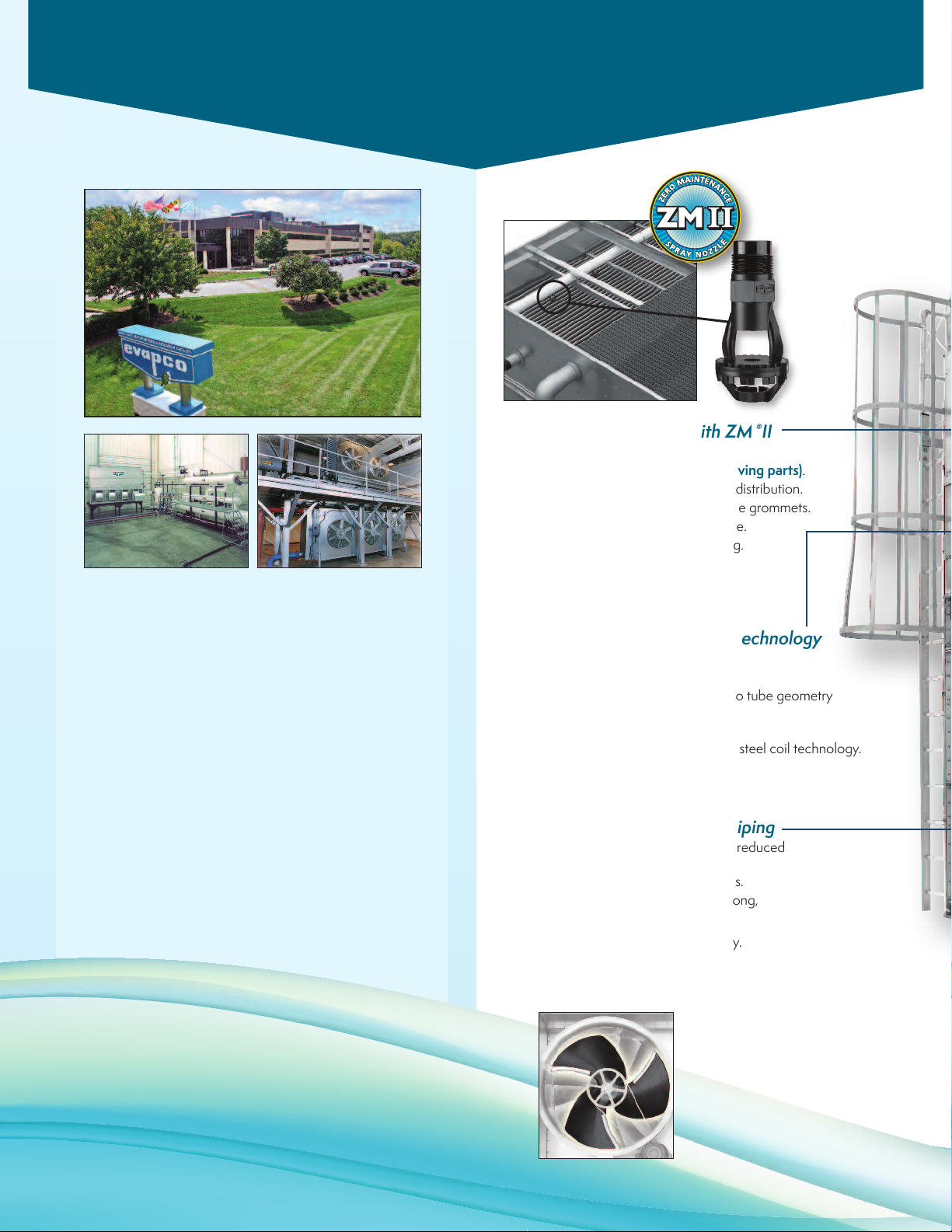
PVC Water Distribution with ZM®II
Nozzles
• Large orifice prevents clogging (no moving parts).
• Redesigned nozzles for superior water distribution.
• Threaded nozzles eliminate troublesome grommets.
• Fixed position require zero maintenance.
• Threaded end caps for ease of cleaning.
• Guaranteed for life.
About EVAPCO
Evapco is the global innovator in heat transfer
solutions. Our pledge is to make everyday
life easier, more comfortable, more reliable,
and more sustainable for people everywhere.
With manufacturing facilities and sales offices
in more than 40 countries and 28 patents
worldwide in the last 10 years alone—we are
the team that engineers and contractors
know they can count on for life.
Contact
your local Evapco Representative
or visit evapco.com to learn more.
2
Thermal Pak®II Heat Transfer Technology
• More surface area per plan area than
competitive designs.
• Improved heat transfer efficiency due to tube geometry
and orientation of tubes.
• Lower refrigerant charge.
• Optional 304L or 316L TITAN stainless steel coil technology.
Improved Water Distribution Piping
• Horizontally mounted pumps allow for reduced
basin water level.*
• Simplified piping for easier basin access.
• Totally enclosed pump motors assure long,
trouble-free life.
*Refer to engineering data for availability.
Optional
Super Low Sound Fan
(Shown in Photograph)
• Extremely wide chord fan
blades for sound sensitive
applications.
• One piece molded heavy duty
construction.
• 10-13 dB(A) sound reduction on
fan side at 50 ft.
Page 3
M
O
T
O
R
A
N
D
D
R
I
V
E
W
A
R
R
A
N
T
Y
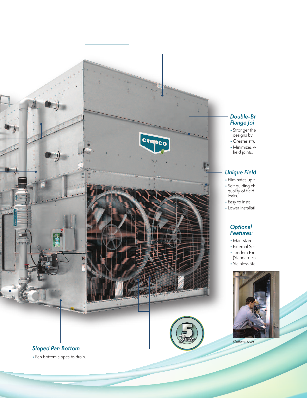
The industry standard for forced draft axial fan condensers. The PMC-E is equipped with
owner-oriented features and benefits that make it Easy
to install... Easy to maintain... Easy on
the operating budget...The Easy Choice!
Water Saver Drift Eliminators
• Patented design reduces drift rate to 0.001%.
• Saves water and reduces water treatment cost.
• Greater structural integrity vs.old style blade-type.
• Recessed into casing for greater protection.
U.S. Patent No. 6315804
Double-Brake
Flange Joints
• Stronger than single-brake
designs by others.
• Greater structural integrity.
• Minimizes water leaks at
field joints.
Unique Field Seam
• Eliminates up to 85% of fasteners.
• Self guiding channels improve
quality of field seam to eliminate
leaks.
• Easy to install.
• Lower installation cost.
Optional Design
Features:
• Man-sized Access Doors.
• External Service Platforms.
• Tandem Fan Drive System
(Standard Fan Only).
• Stainless Steel Construction.
Optional Man-sized Access Door
Sloped Pan Bottom
• Pan bottom slopes to drain.
• Easy to clean.
• Stainless steel strainer resists
corrosion.
Individual Fan Drive System
• Increased flexibility for improved capacity control.
• Greater reliability through redundancy.
• Easy motor replacement.
• Front mounted drives for improved maintenance accessibility.
3
Page 4
PMC-E Design Features
ST AND ARD!SSTSTASTANSTANDSTANDASTANDA RSTANDA R DSTANDA R D!STANDARD!
Proven Performance & Design Flexibility
The PMC-E Evaporative Condenser offers more capacity and greater system
design flexibility than ever before. EVAPCO's research and development
team has invested hundreds of hours in laboratory testing to develop the
next generation in Forced Draft Condenser Technology. These efforts have
produced an efficient fan section design combined with the proven Thermal-
®
coil technology to offer improved condenser performance.
Pak II
The PMC-E features more plan area options and fan horsepower options for
the system design engineer. With more condenser capacity, more plan area
options and greater flexibility in motor selection, the design engineer can
now match the condenser performance to the specific application requirements. More equipment choices and more design flexibility mean greater
value for the End-User.
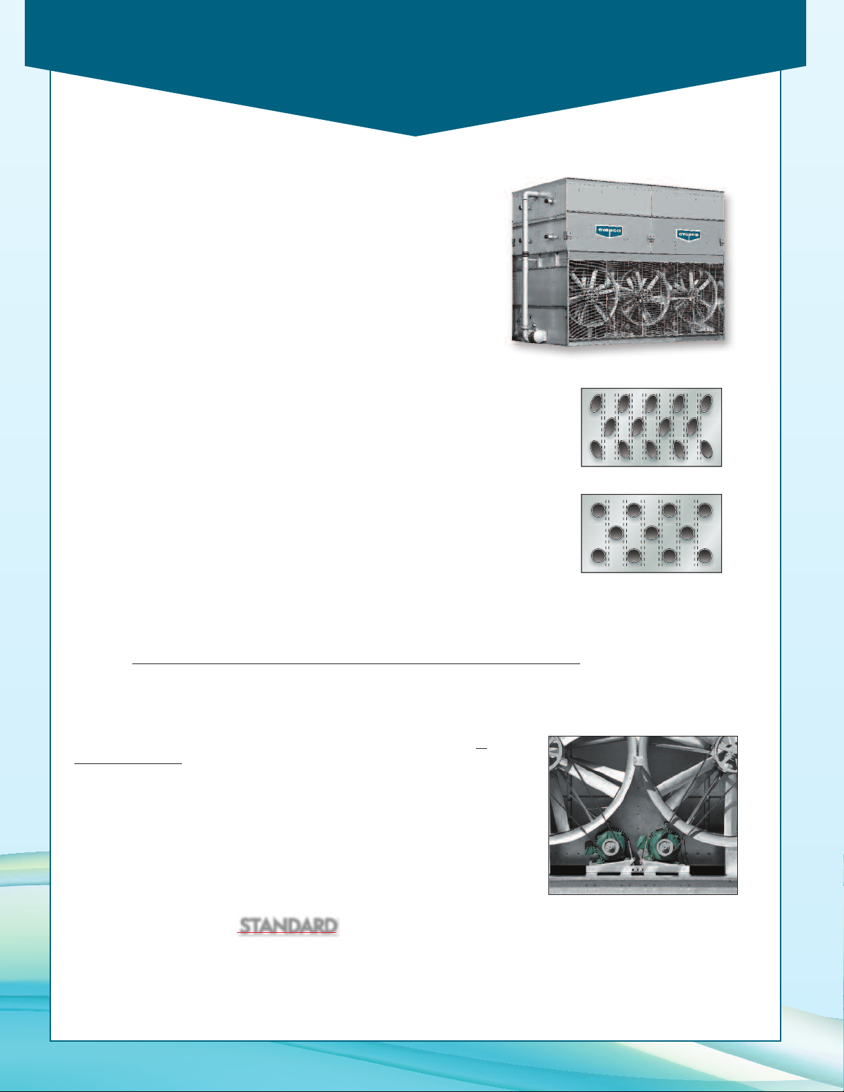
Thermal-Pak II®Coil Design
Lower Refrigerant Charge
Only EVAPCO condensers offer the unique Thermal-Pak II
operating efficiency in your condenser. Its unique elliptical tube design allows for closer
tube spacing resulting in more surface area per plan area than traditional round tube
designs. The Thermal-Pak II
greater water loading, making the Thermal-Pak II®Coil the most efficient design available
and yields a low refrigerant charge.
®
Coil design has lower resistance to air flow and permits
®
Coil which assures greater
Thermal-Pak II®Coil by EVAPCO
Energy Efficient for Lowest Operating Cost
Lower Horsepower Options
The fan drive system of the PMC-E utilizes large diameter vane-axial fans in a two stage arrangement to provide more
efficient air flow and reduced power consumption. When compared to the traditional centrifugal fan condenser models,
the vane-axial fan design can offer up to a 50% reduction in energy consumption. And, with the new PMC-E model
selections even more low horsepower options are available to obtain greater energy savings
Round Tube Coil by Others
.
Individual Fan Drive System
Capacity Control Flexibility & Operating Redundancy
The PMC-E fan drive system provides individual motor to fan configuration as
standard equipment on all models. The dedicated fan to motor arrangement ensures
less “wear & tear” on the drive system versus tandem fan motor drive arrangements
resulting in less maintenance. The individual motor to fan design offers greater
capacity control flexibility to match the system load requirements. In addition, all
Evapco condensers are equipped with an internal baffle system which extends from
the pan bottom vertically through the coil bundle. This unique design allows the user
to cycle fan motors independently without harmful effects of air by-pass inside the
unit. The individual motor to fan design ensures maximum operating redundancy in
the condenser fan system when critical operation is necessary. The PMC-E comes
standard with a 5 Year motor and drive warranty.
Inverter Duty Motors
Inverter Duty motors are standard on PMC-E Condensers. Inverter Duty motors are totally enclosed, premium efficiency and
inverter capable (VFD by others).
Note: Variable Frequency Drive control may require other component modification such as motor shaft grounding
brushes, AC load reactors, low pass filters and tuned trap filters to ensure proper motor performance and service life.
4
Page 5
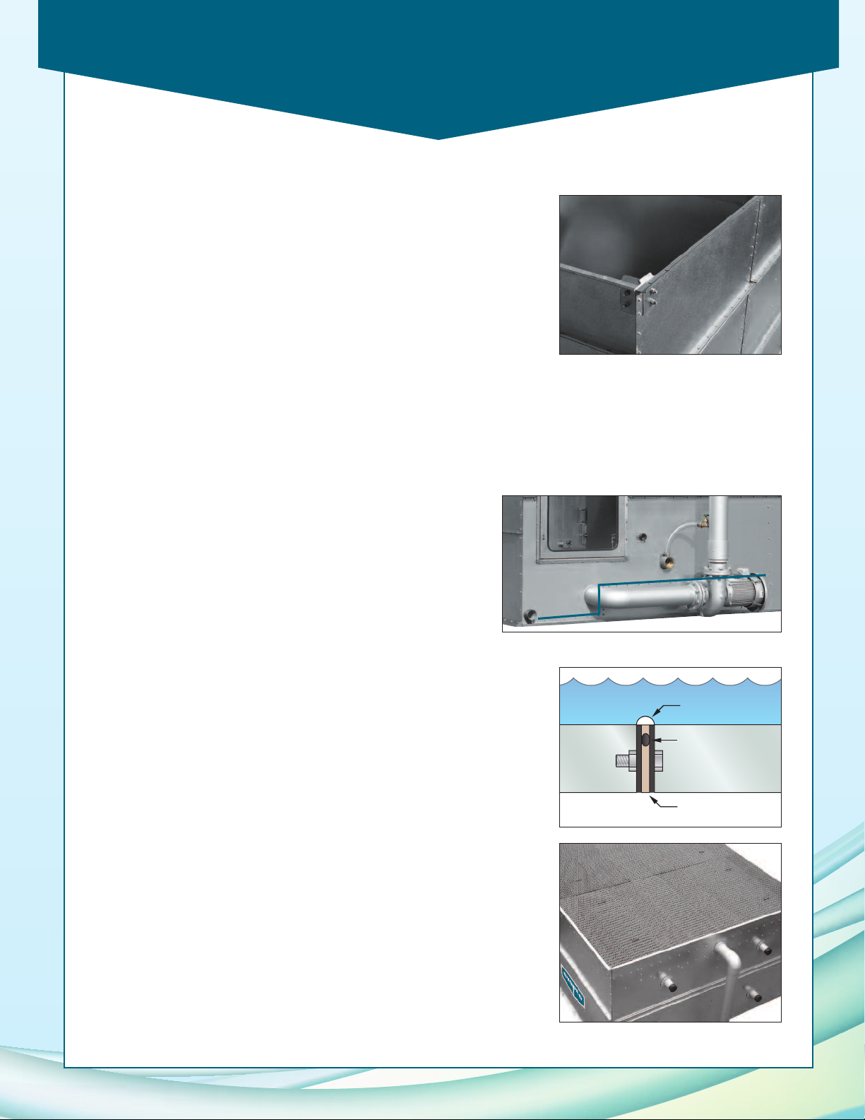
PMC-E Design Features
Overlay
Sealant
Anti-Leak
Sealer Strip
Integral
Compression
Shim
Easy Field Assembly
Fewer Fasteners
Lower Installed Cost
The PMC-E features a field seam design which ensures easier assembly and fewer
field seam leaks. The field seam incorporates self-guiding channels to guide the
coil casing section into position and set in place on the bottom fan section of the
condenser. In addition, the design eliminates up to 85% of the required fasteners
typically used to join the condenser sections in the field significantly reducing the
contractor labor costs for installation.
Improved Maintenance
Fan Drive Accessibility
The drive components of the PMC-E are easily accessed for routine maintenance from the front of the unit. Bearing
grease fittings are extended to the outside of the unit for ease of lubrication. All drive sheaves have been relocated to
the front of the fan section and motors are positioned on a platform base to allow for easy belt tension adjustment.
Easy Clean Sloped Basin
The PMC-E basin is designed to improve maintenance access and make
it easier for operating technicians to clean. The bottom of the pan is
sloped to the unit drain to ensure that the basin will completely drain
and allow sediment and debris that may collect in the basin to be easily
flushed from the unit. The design helps to prevent buildup of
sedimentary deposits, biological films and standing water. In addition,
Evapco offers a special “man-sized” access door option to improve
access to this critical area of the unit.
Construction Features
Unique Seam Design–Eliminate Field Leaks
The PMC-E features Evapco's unique panel construction design which includes a
special butyl tape sealer with an integral sealing gasket. Each joint is then backed
with a secondary caulking compound and encased in a double-brake flange for
added strength and structural integrity. This unique sealing system has been
proven effective in both laboratory tests and years of field application.
Superior Water Saver Drift Eliminators
The PMC-E condensers incorporate a patented* highly efficient PVC drift
eliminator. The eliminator removes entrained water droplets from the air stream
to limit the drift rate to less than 0.001% of the recirculating water rate. With a
low drift rate, PMC-E condensers save valuable water and water treatment
chemicals. The eliminators feature a honeycomb design which offers greater
structural integrity and are recessed in the top of the casing and UV protected
for longer life. They are constructed of inert polyvinyl chloride (PVC) which
eliminates corrosion in this critical area of the condenser. The eliminators are
assembled in sections for easy handling and removal for coil and water
distribution system inspection.
*U.S. Patent No. 6315804
5
Page 6
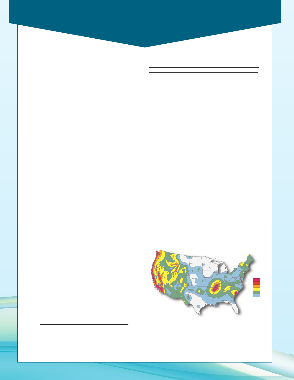
IBC Compliance
32+
Highest Hazard
Lowest Hazard
%g
24-32
16-24
8-16
4-8
2-4
0-2
IBC Compliance
EVAPCO has been applying advanced structural technology to
evaporative condensers for many years. Following seismic
events in the mid 1990’s EVAPCO introduced the UB Series of
nduced draft cooling towers, fluid coolers and evaporative
i
condensers. These products were designed, built and
independently certified for extreme seismic and wind forces.
With the advent of the International Building Code, EVAPCO is
offering the PMC-E Evaporative Condensers that are IBC
2006 compliant as standard construction.
International Building Code
The International Building Code (IBC) is a comprehensive set
of regulations addressing the structural design and installation
requirements for building systems – including HVAC and
industrial refrigeration equipment. As of June 2008, all 50
states plus Washington D.C have adopted the International
Building Code. Compared to previous building codes that
solely examined anchorage, the earthquake provisions
contained within the International Building Code address
anchorage, structural integrity, and operational capability of a
component following a seismic event. The goal of the IBC is
to minimize the loss of life and improve the capability of
essential facilities to operate after a seismic event.
The International Building Code (IBC) was developed to
replace the BOCA National Building Code, ICBO’s Uniform
Building Code and SBCCI’s Standard Building Code. The
International Building Code specifies that all components be
designed to resist the equivalent seismic forces as the
structure to which they are installed whereas previous building
codes focused exclusively on the structure of the building to
provide resistance against seismic forces. These components
include all aspects of the building architectural, electrical and
mechanical systems. The failure of these components during a
seismic event has been a common occurrence in recent
history. Although the structure of the building may be
relatively undamaged from an earthquake, the damage to the
nonstructural components could be significant and result in
considerable secondary damage to the building (ie. flooding,
fire, structural damage).
forces prescribed in the code. Simply stated, the code
provisions require that evaporative cooling equipment and all
other components permanently installed on a structure must
meet the same seismic design criteria as the building.
The seismic design force, utilized for component design,
represents an equivalent static force that is applied to the
components’ center of gravity as described in the following
equation:
Fp= [(0.4 * (ap) * (SDS) * (Wp)) / (Rp/ Ip)] * (1 + 2 * (z / h))
Fp= Seismic Design Force centered at the component’s
center of gravity
S
= Design spectral response acceleration, short period
S
D
a
= Component amplification factor
p
I
= Component importance factor
p
W
= Component operating weight
p
R
= Component response modification factor
p
z = Height in structure of point of attachment of
component with respect to the base
h = Average roof height of structure with respect to
the base
The minimum and maximum design force limits are specified as:
Fp-min = 0.3 SDS IpW
Fp-max = 1.6 SDS IpW
p
p
A series of charts and graphs are used to determine the
appropriate factors based on the location of the installation
and ultimately the “importance” of the facility. A chart of the
potential seismic activity in the United States is shown below.
Seismic Design
The IBC specifies that all installed components must meet the
requirements of ASCE 7-05 (American Society of Civil
Engineers, Minimum Design Loads for Buildings and Other
Structures). Exemptions noted in the code are for all
mechanical components assigned to seismic design categories
A or B. ASCE 7-05 explicitly states that in addition to the
attachment and supports, the component itself must be
designed to withstand the seismic
6
Map courtesy US Geological Survey website
Page 7
IBC Compliance
Certificate of Compliance
AT, USS, UAT, UT Cooling Towers
eco-ATWB/WB-E, ATWB and ESWA Closed Circuit Coolers
eco-ATCA, ATC-E and PHC Evaporative Condensers
Are certified to meet or exceed the Seismic and Wind Load Provisions
set forth in the applicable building codes for this project.
These products have been manufactured following all
applicable quality assurance programs.
Applicable Building Codes:
IBC 2012
ASCE-7
NFPA 5000
Approval Ag enc y:
Tobolski Watkins Engineering, Inc.
EVAPCO...Specialists in Heat Transfer Products and Services.
Seismic and Wind Load Certification
AT, USS, UAT, UT Cooling Towers
eco-ATWB/WB-E, ATWB and ESWA Closed Circuit Coolers
eco-ATCA, ATC-E and PHC Evaporative Condensers
Units Designed and Manufactured to Meet the
Seismic & Wind Load Requirements of:
IBC 2012 ASCE-7 NFPA 5000
Independent Certification By:
Tobolski Watkins Engineering, Inc.
Importance Factor (Ip)
A major parameter that must be determined prior to
calculating the seismic design force is the component
importance factor (Ip). ASCE 7-05 defines the
component importance factor as:
Importance
Factor, Ip
• Life safety component required to function
after seismic event.
1.5
1.0 All other components
• Component containing hazardous content
• Components installed at Group III
(essential) facilities
Products such as ammonia refrigerant condensers should
always be assigned an importance factor of 1.5 since they
contain ammonia. The IBC identifies ammonia as
hazardous content in reference of OSHA standards.
According to the American Society of Civil Engineers
(ASCE) Manual, 07-05 edition, section 13.1.3, hazardous
materials require an importance factor of 1.5.
Classification
Design Implementation
In order to achieve this goal, an architect or civil engineer
is responsible for analyzing the soil and the design of a
structure to determine the factors to be used. A
mechanical consulting engineer and/or design build
contractor applies these factors to advise the
manufacturer on the proper design for the application.
EVAPCO takes this information and determines the
necessary equipment to meet IBC regulations. Evapco
then determines the condenser design requirements
based on the IBC criteria. The standard PMC-E design is
independently certified to meet the 1g IBC compliance
factors. For applications that require a more severe
seismic duty, EVAPCO offers an optional 5.12g
construction design. This process ensures that the
mechanical equipment and its components are seismically
compliant per the provisions of the International Building
Code.
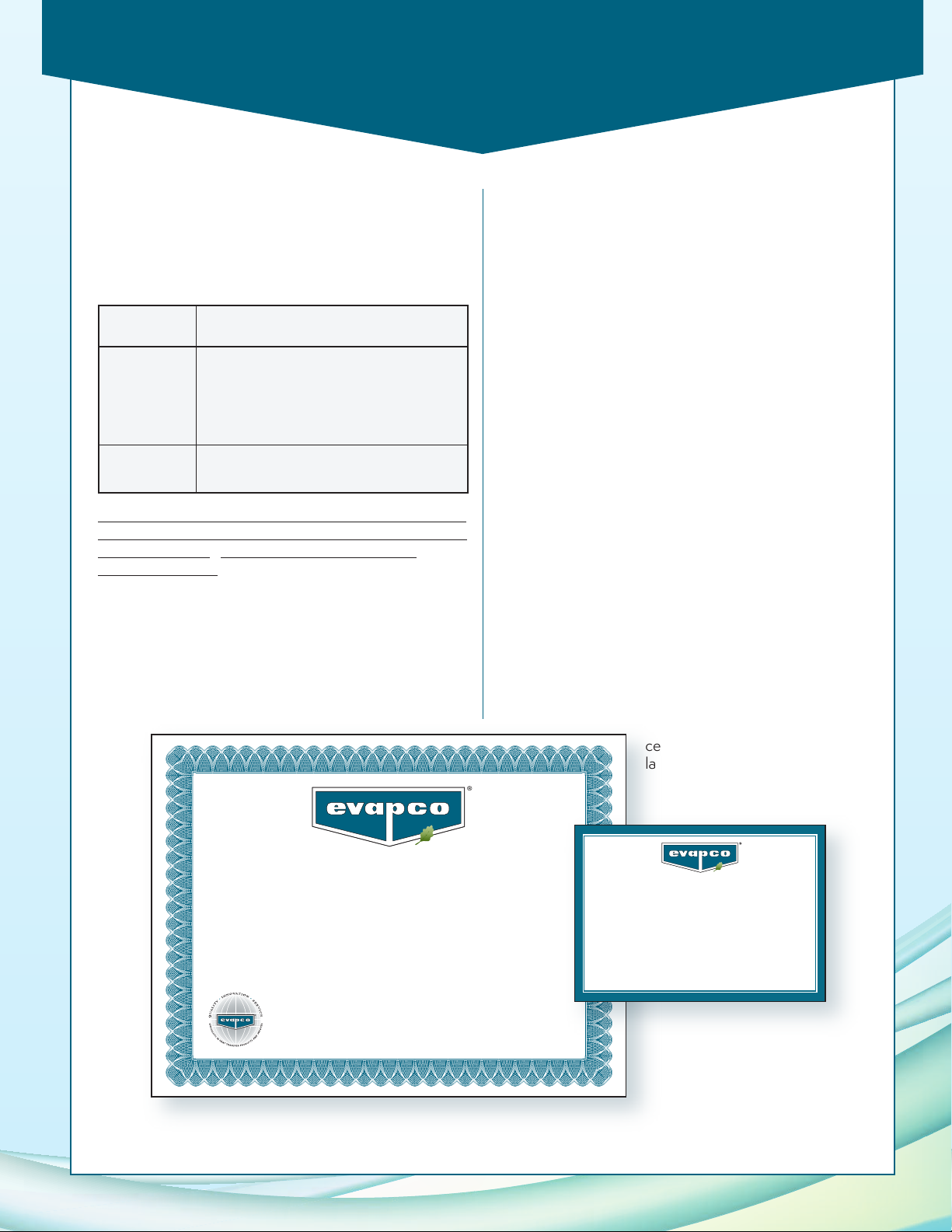
Independent Certification
As required by the International Building Code, EVAPCO
supplies a certificate of compliance as part of its
submittal documents. The certificate of compliance
should demonstrate that the equipment/unit has been
independently tested and analyzed in accordance with
the IBC program. Evapco has worked closely with
Vibrations Mountings and Controls Group (VMC) to
complete the independent equipment testing and
analysis. A sample of the
certificate of compliance and unit
label is presented below:
7
Page 8
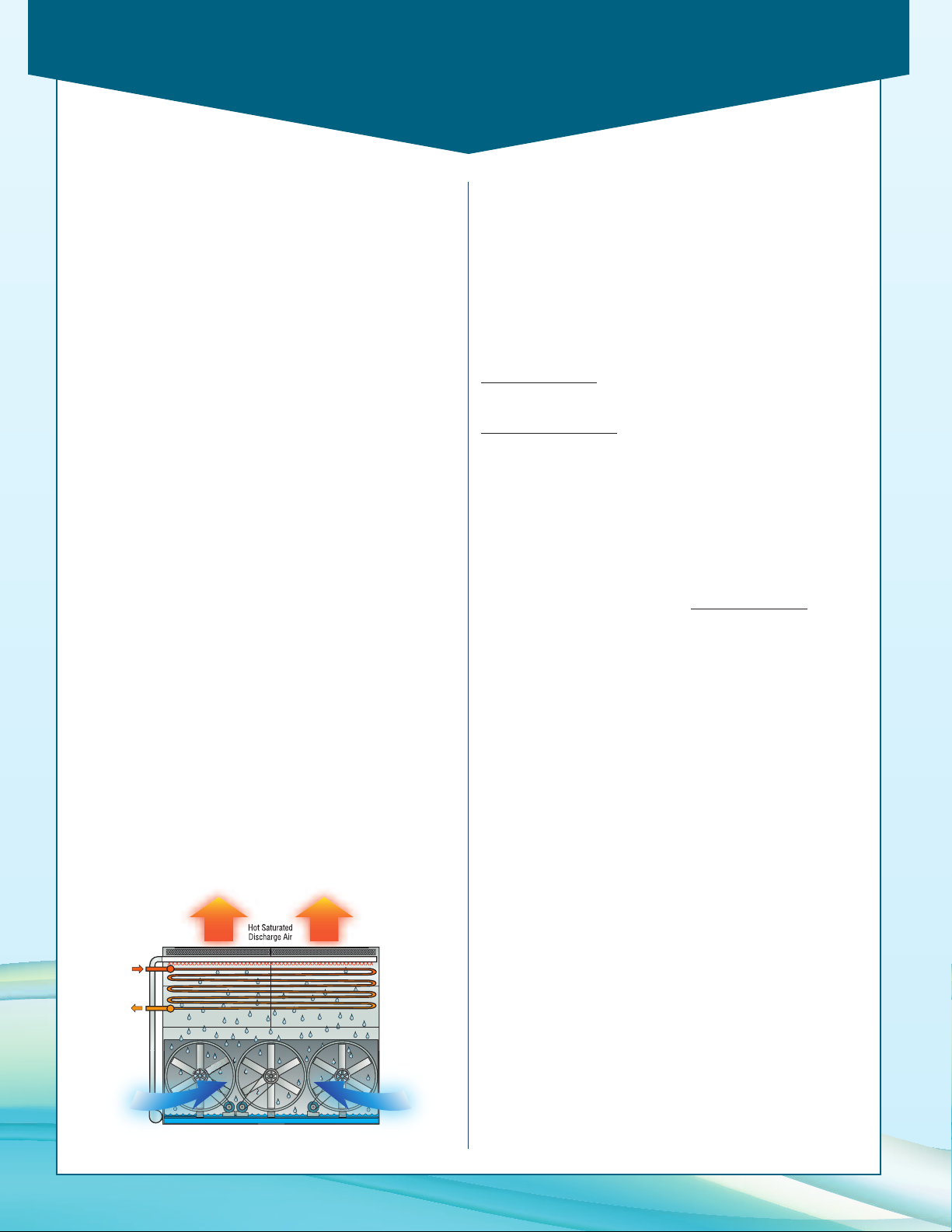
PMC-E Selection Procedure
Superheated
Refrigerant
Gas In
Hot Saturated
Discharge Air
Condensed
Refrigerant
Liquid Out
Cool Dry
Entering Air
Selection Procedure
wo methods of selection are presented, the first is based on
T
the total heat of rejection as described immediately below.
The second and more simple method is based on evaporator
tons. The evaporator ton method is only applicable to systems
ith open type reciprocating compressors.
w
The heat of rejection method is applicable to all but
centrifugal compressor applications and is normally used for
selecting evaporative condensers for use with hermetic
compressors and screw compressors. It can also be used for
standard open type reciprocating compressors as an alternate
to the evaporator ton method.
The evaporator ton method is based on the estimated heat of
compression. The heat of rejection method of selection is
more accurate and should be used whenever possible.
Refer to the factory for selections on systems with centrifugal
compressors.
Principle of Operation
The refrigerant gas is discharged from the compressor into the
inlet connection of the evaporative condenser. Water from
the condenser’s sump is continuously flooded over the
condenser coil, while ambient air is simultaneously forced into
the unit. As the ambient air moves up through the coil section,
a portion of the spray water is evaporated into the air stream.
The evaporative process cools the spray water, which in turn
cools the tubes containing the refrigerant gas. The cool tube
walls cause the refrigerant gas to give up heat and condense
into a liquid. The condensed liquid flows out of the coil’s
sloping tubes to the high pressure liquid receiver for return to
the system.
The hot, saturated air is driven through the drift eliminators,
where any entrained water droplets are removed. The
condenser’s fan then discharges this air stream out of the top
of the unit at a high velocity, where it can dissipate harmlessly
into the atmosphere. The water which was not evaporated
falls into the sump and is recirculated by the spray pump to the
water distribution system above the condensing coil section.
Heat of Rejection Method
In the heat of rejection method, a factor for the specified
operating conditions (condensing temperature and wet bulb) is
obtained from Table 1 or 2 and multiplied times the heat of
rejection.
The resultant figure is used to select a unit from Table 3. Unit
capacities are given in Table 3 in thousands of BTU/Hr or
MBH.
If the heat of rejection is not known, it can be determined by
one of the following formulas:
Open Compressors
Heat of Rejection = Evaporator Load (BTU/Hr) +
Compressor BHP x 2545
Hermetic Compressors
Heat of Rejection = Evaporator Load (BTU/Hr) + K.W.
Compressor Input x 3415
EXAMPLE
Given: 450 ton load, ammonia refrigerant 96.3° condensing
temperature, 78° W.B. temperature and 500 compressor BHP.
Selection: Heat of Rejection
From Table 2 the capacity factor for 96.3° condensing and
78° W.B. = 1.37 6,672,500 x 1.37 = 9,141,325 BTU/Hr or
9142 MBH. Therefore, select a model PMC-631E.
Note: For screw compressor selections employing water
cooled oil cooling, select a condenser for the total MBH as in
the example. The condenser can then function in one of two
ways:
(1) Recirculating water from the water sump can be used
directly in the oil cooler. A separate pump should be
employed and the return water should be directed into the
water sump at the opposite end from the pump suction.
(2) The condenser coil can be circuited so that water or a
glycol-water mixture for the oil cooler can be cooled in a
separate section of the coil. Specify load and water flow
required.
:
:
450 tons x 12000 = 5,400,000 BTU/Hr
500 BHP x 2545 = 1,272,500 BTU/Hr
Total 6,672,500 BTU/Hr
For refrigerant injection cooled screw compressors, select the
condenser in the same manner as shown in the example.
Principle of Operation
If the oil cooler is supplied by water from a separate source,
then the oil cooling load should be deducted from the heat of
rejection before making the selection.
8
Page 9
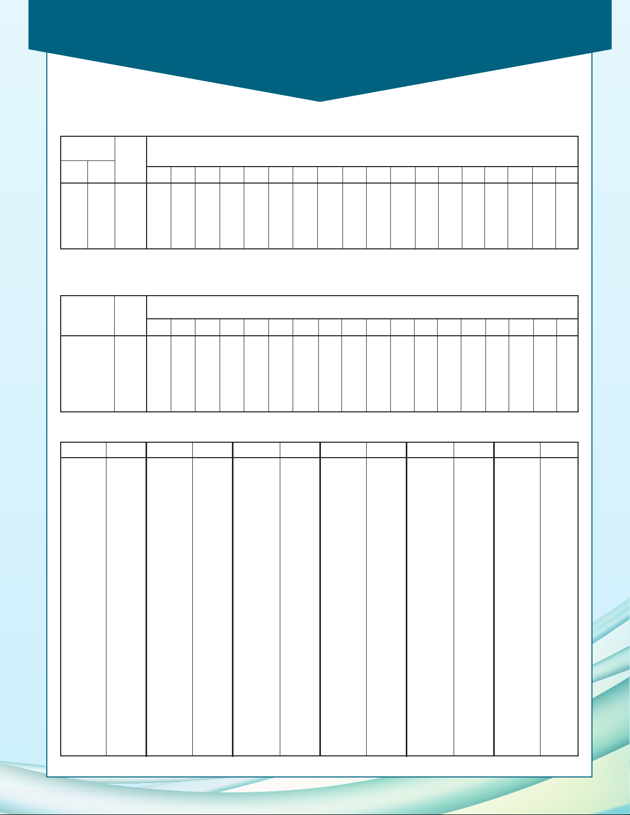
PMC-E Selection Procedure
Table 1 - HCFC-22 and HFC-134a Heat Rejection Factors
Condensing
Pres. psig
HCFC-
22
HFC-
134a
Cond.
Temp.
°F
Wet Bulb Temperature, (°F)
50 55 60 62 64 66 68 70 72 74 75 76 77 78 80 82 84 86
156 95 85 1.10 1.22 1.39 1.50 1.61 1.75 1.93 2.13 2.42 2.78 3.02 3.29 3.64 4.00 ---168 104 90 .93 1.02 1.14 1.21 1.28 1.36 1.45 1.57 1.71 1.89 2.00 2.12 2.25 2.38 2.85 3.50 -182 114 95 .80 .87 .95 1.00 1.05 1.10 1.15 1.22 1.31 1.40 1.45 1.50 1.56 1.64 1.82 2.07 2.37 2.77
196 124 100 .71 .76 .82 .85 .88 .91 .94 .98 1.03 1.09 1.12 1.15 1.20 1.24 1.34 1.46 1.63 1.82
211 135 105 .63 .66 .70 .72 .75 .77 .80 .83 .87 .91 .93 .95 .97 1.00 1.06 1.13 1.23 1.35
226 146 110 .56 .59 .62 .64 .65 .67 .69 .71 .74 .77 .78 .80 .82 .84 .88 .93 .98 1.04
Note: Consult factory for selections using other refrigerants.
Table 2 - Ammonia (R-717) Heat Rejection Factors
Condensing Cond.
Pres. Temp.
psig °F
50 55 60 62 64 66 68 70 72 74 75 76 77 78 80 82 84 86
152 85 .98 1.09 1.24 1.34 1.44 1.56 1.72 1.90 2.16 2.48 2.70 2.94 3.25 3.57 ---166 90 .83 .91 1.02 1.08 1.14 1.21 1.29 1.40 1.53 1.69 1.79 1.89 2.01 2.12 2.54 3.12 --
181 95 .71 .78 .85 .89 .94 .98 1.03 1.09 1.17 1.25 1.29 1.34 1.39 1.47 1.63 1.85 2.12 2.47
185 96.3 .69 .75 .82 .86 .90 .94 .98 1.03 1.10 1.18 1.22 1.26 1.31 1.37 1.51 1.71 1.94 2.25
197 100 .63 .68 .73 .76 .79 .81 .84 .87 .92 .97 1.00 1.03 1.07 1.11 1.20 1.30 1.46 1.63
214 105 .56 .59 .62 .64 .67 .69 .71 .74 .78 .81 .83 .85 .87 .89 .95 1.01 1.10 1.21
232 110 .50 .53 .55 .57 .58 .60 .62 .63 .66 .69 .70 .71 .73 .75 .79 .83 .87 .93
Wet Bulb Temperature, (°F)
Table 3 - Unit Heat Rejection
Model MBH Base
PMC-175E 2572.5
PMC-190E 2793.0
PMC-210E 3087.0
PMC-220E 3234.0
PMC-235E 3454.5
PMC-240E 3528.0
PMC-250E 3675.0
PMC-275E 4042.5
PMC-295E 4336.5
PMC-325E 4777.5
PMC-332E 4880.4
PMC-335E 4924.5
PMC-360E 5292.0
PMC-362E 5321.4
PMC-369E 5424.3
PMC-375E 5512.5
PMC-376E 5527.2
PMC-386E 5674.2
PMC-397E 5835.9
PMC-400E 5880.0
PMC-408E 5997.6
PMC-411E 6041.7
PMC-420E 6174.0
PMC-426E 6262.2
PMC-427E 6276.9
PMC-428E 6291.6
PMC-431E 6335.7
PMC-450E 6615.0
PMC-453E 6659.1
PMC-456E 6703.2
Model MBH Base
PMC-457E 6717.9
PMC-464E 6820.8
PMC-479E 7041.3
PMC-481E 7070.7
PMC-488E 7173.6
PMC-491E 7217.7
PMC-492E 7232.4
PMC-495E 7276.5
PMC-501E 7364.7
PMC-503E 7394.1
PMC-513E 7541.1
PMC-515E 7570.5
PMC-519E 7629.3
PMC-530E 7791.0
PMC-536E 7879.2
PMC-537E 7893.9
PMC-545E 8011.5
PMC-546E 8026.2
PMC-558E 8202.6
PMC-559E 8217.3
PMC-564E 8290.8
PMC-568E 8349.6
PMC-579E 8511.3
PMC-591E 8687.7
PMC-596E 8761.2
PMC-600E 8820.0
PMC-601E 8834.7
PMC-602E 8849.4
PMC-605E 8893.5
PMC-616E 9055.2
Model MBH Base
PMC-631E 9275.7
PMC-634E 9319.8
PMC-636E 9349.2
PMC-640E 9408.0
PMC-641E 9422.7
PMC-645E 9481.5
PMC-647E 9510.9
PMC-668E 9819.6
PMC-675E 9922.5
PMC-679E 9981.3
PMC-688E 10113.6
PMC-690E 10143.0
PMC-691E 10157.7
PMC-715E 10510.5
PMC-719E 10569.3
PMC-723E 10628.1
PMC-725E 10657.5
PMC-731E 10745.7
PMC-735E 10804.5
PMC-737E 10833.9
PMC-751E 11039.7
PMC-752E 11054.4
PMC-772E 11348.4
PMC-774E 11377.8
PMC-778E 11436.6
PMC-796E 11701.2
PMC-800E 11760.0
PMC-801E 11774.7
PMC-803E 11804.1
PMC-811E 11921.7
Model MBH Base
PMC-819E 12039.3
PMC-816E 11995.2
PMC-831E 12215.7
PMC-840E 12348.0
PMC-852E 12524.4
PMC-853E 12539.1
PMC-856E 12583.2
PMC-863E 12686.1
PMC-888E 13053.6
PMC-889E 13068.3
PMC-894E 13141.8
PMC-895E 13156.5
PMC-900E 13230.0
PMC-905E 13303.5
PMC-911E 13391.7
PMC-913E 13421.1
PMC-929E 13656.3
PMC-939E 13803.3
PMC-940E 13818.0
PMC-949E 13950.3
PMC-954E 14023.8
PMC-955E 14038.5
PMC-956E 14053.2
PMC-962E 14141.4
PMC-974E 14317.8
PMC-976E 14347.2
PMC-980E 14406.0
PMC-983E 14450.1
PMC-989E 14538.3
PMC-992E 14582.4
Model MBH Base
PMC-1002E 14729.4
PMC-1004E 14758.8
PMC-1006E 14788.2
PMC-1013E 14891.1
PMC-1021E 15008.7
PMC-1024E 15052.8
PMC-1038E 15258.6
PMC-1056E 15523.2
PMC-1070E 15729.0
PMC-1071E 15743.7
PMC-1072E 15758.4
PMC-1073E 15773.1
PMC-1088E 15993.6
PMC-1116E 16405.2
PMC-1117E 16419.9
PMC-1125E 16537.5
PMC-1127E 16566.9
PMC-1137E 16713.9
PMC-1148E 16875.6
PMC-1180E 17346.0
PMC-1182E 17375.4
PMC-1189E 17478.3
PMC-1201E 17654.7
PMC-1203E 17684.1
PMC-1205E 17713.5
PMC-1211E 17801.7
PMC-1258E 18492.6
PMC-1261E 18536.7
PMC-1269E 18654.3
PMC-1275E 18742.5
Model MBH Base
PMC-1286E 18994.2
PMC-1290E 18963.0
PMC-1296E 19051.2
PMC-1333E 19595.1
PMC-1358E 19962.6
PMC-1376E 20227.2
PMC-1382E 20315.4
PMC-1438E 21138.6
PMC-1446E 21256.2
PMC-1466E 21550.2
PMC-1473E 21653.1
PMC-1549E 22770.3
PMC-1556E 22873.2
PMC-1586E 23314.2
PMC-1599E 23505.3
PMC-1625E 23887.5
PMC-1705E 25063.5
PMC-1712E 25166.4
PMC-1776E 26107.2
PMC-1788E 26283.6
PMC-1811E 26621.7
PMC-1877E 27591.9
PMC-1879E 27621.3
PMC-1911E 28091.7
PMC-1913E 28121.1
PMC-1985E 29179.5
PMC-2019E 29679.3
9
Page 10
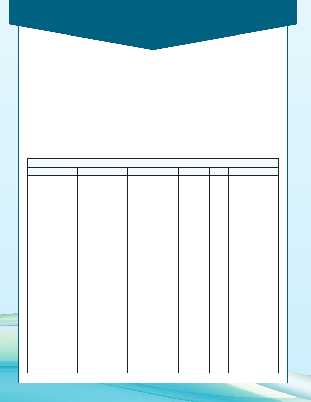
PMC-E Selection Procedure
Evaporator Ton Method
In the evaporator ton method, factors for the specified
operating conditions (suction temperature, condensing
temperature and wet bulb) are obtained from either Table
5 or 6 and multiplied times the heat load in tons. The
resultant figure is used to select a unit from Table 4. The
condenser model in Table 4 is equal to the unit capacity in
evaporator tons for HCFC-22 or HFC-134a conditions of
105°F condensing, 40°F suction and 78° wet bulb.
Table 4 - Unit Sizes
PMC-E Models
Model Capacity
PMC-175E 175
PMC-190E 190
PMC-210E 210
PMC-220E 220
PMC-235E 235
PMC-240E 240
PMC-250E 250
PMC-275E 275
PMC-295E 295
PMC-325E 325
PMC-332E 332
PMC-335E 335
PMC-360E 360
PMC-362E 362
PMC-369E 369
PMC-375E 375
PMC-376E 376
PMC-386E 386
PMC-397E 397
PMC-400E 400
PMC-408E 408
PMC-411E 411
PMC-420E 420
PMC-426E 426
PMC-427E 427
PMC-428E 428
PMC-431E 431
PMC-450E 450
PMC-453E 453
PMC-456E 456
PMC-457E 457
PMC-464E 464
PMC-479E 479
PMC-481E 481
PMC-488E 488
PMC-491E 491
Model Capacity Model Capacity Model Capacity Model Capacity
PMC-492E 492
PMC-495E 495
PMC-501E 501
PMC-503E 503
PMC-513E 513
PMC-515E 515
PMC-519E 519
PMC-530E 530
PMC-536E 536
PMC-537E 537
PMC-545E 545
PMC-546E 546
PMC-558E 558
PMC-559E 559
PMC-564E 564
PMC-568E 568
PMC-579E 579
PMC-591E 591
PMC-596E 596
PMC-600E 600
PMC-601E 601
PMC-602E 602
PMC-605E 605
PMC-616E 616
PMC-631E 631
PMC-634E 634
PMC-636E 636
PMC-640E 640
PMC-641E 641
PMC-645E 645
PMC-647E 647
PMC-668E 668
PMC-675E 675
PMC-679E 679
PMC-688E 688
PMC-690E 690
PMC-691E 691
PMC-715E 715
PMC-719E 719
PMC-723E 723
PMC-725E 725
PMC-731E 731
PMC-735E 735
PMC-737E 737
PMC-751E 751
PMC-752E 752
PMC-772E 772
PMC-774E 774
PMC-778E 778
PMC-796E 796
PMC-800E 800
PMC-801E 801
PMC-803E 803
PMC-811E 811
PMC-819E 819
PMC-816E 816
PMC-831E 831
PMC-840E 840
PMC-852E 852
PMC-853E 853
PMC-856E 856
PMC-863E 863
PMC-888E 888
PMC-889E 889
PMC-894E 894
PMC-895E 895
PMC-900E 900
PMC-905E 905
PMC-911E 911
PMC-913E 913
PMC-929E 929
PMC-939E 939
EXAMPLE
iven: 300 ton evaporator load, R-717, condensing at 95°
G
F, with +10° F suction and 76° F wet bulb temperatures.
Selection: The capacity factor from Table 6 for the given
condensing and wet bulb conditions is 1.38, and the
capacity factor for the suction temperature of +10° F is
1.03, so the corrected capacity required may be
determined as:
300 X 1.38 X 1.03 = 426 corrected tons. Therefore,
select a model PMC-428E, PMC-431E or PMC-450E
depending on unit type desired, and any layout or
horsepower considerations.
PMC-940E 940
PMC-949E 949
PMC-954E 954
PMC-955E 955
PMC-956E 956
PMC-962E 962
PMC-974E 974
PMC-976E 976
PMC-980E 980
PMC-983E 983
PMC-989E 989
PMC-992E 992
PMC-1002E 1002
PMC-1004E 1004
PMC-1006E 1006
PMC-1013E 1013
PMC-1021E 1021
PMC-1024E 1024
PMC-1038E 1038
PMC-1056E 1056
PMC-1070E 1070
PMC-1071E 1071
PMC-1072E 1072
PMC-1073E 1073
PMC-1088E 1088
PMC-1116E 1116
PMC-1117E 1117
PMC-1125E 1125
PMC-1127E 1127
PMC-1137E 1137
PMC-1148E 1148
PMC-1180E 1180
PMC-1182E 1182
PMC-1189E 1189
PMC-1201E 1201
PMC-1203E 1203
PMC-1205E 1205
PMC-1211E 1211
PMC-1258E 1258
PMC-1261E 1261
PMC-1269E 1269
PMC-1275E 1275
PMC-1286E 1286
PMC-1290E 1290
PMC-1296E 1296
PMC-1333E 1333
PMC-1358E 1358
PMC-1376E 1376
PMC-1382E 1382
PMC-1438E 1438
PMC-1446E 1446
PMC-1466E 1466
PMC-1473E 1473
PMC-1549E 1549
PMC-1556E 1556
PMC-1586E 1586
PMC-1599E 1599
PMC-1625E 1625
PMC-1705E 1705
PMC-1712E 1712
PMC-1776E 1776
PMC-1788E 1788
PMC-1811E 1811
PMC-1877E 1877
PMC-1879E 1879
PMC-1911E 1911
PMC-1913E 1913
PMC-1985E 1985
PMC-2019E 2019
10
Page 11
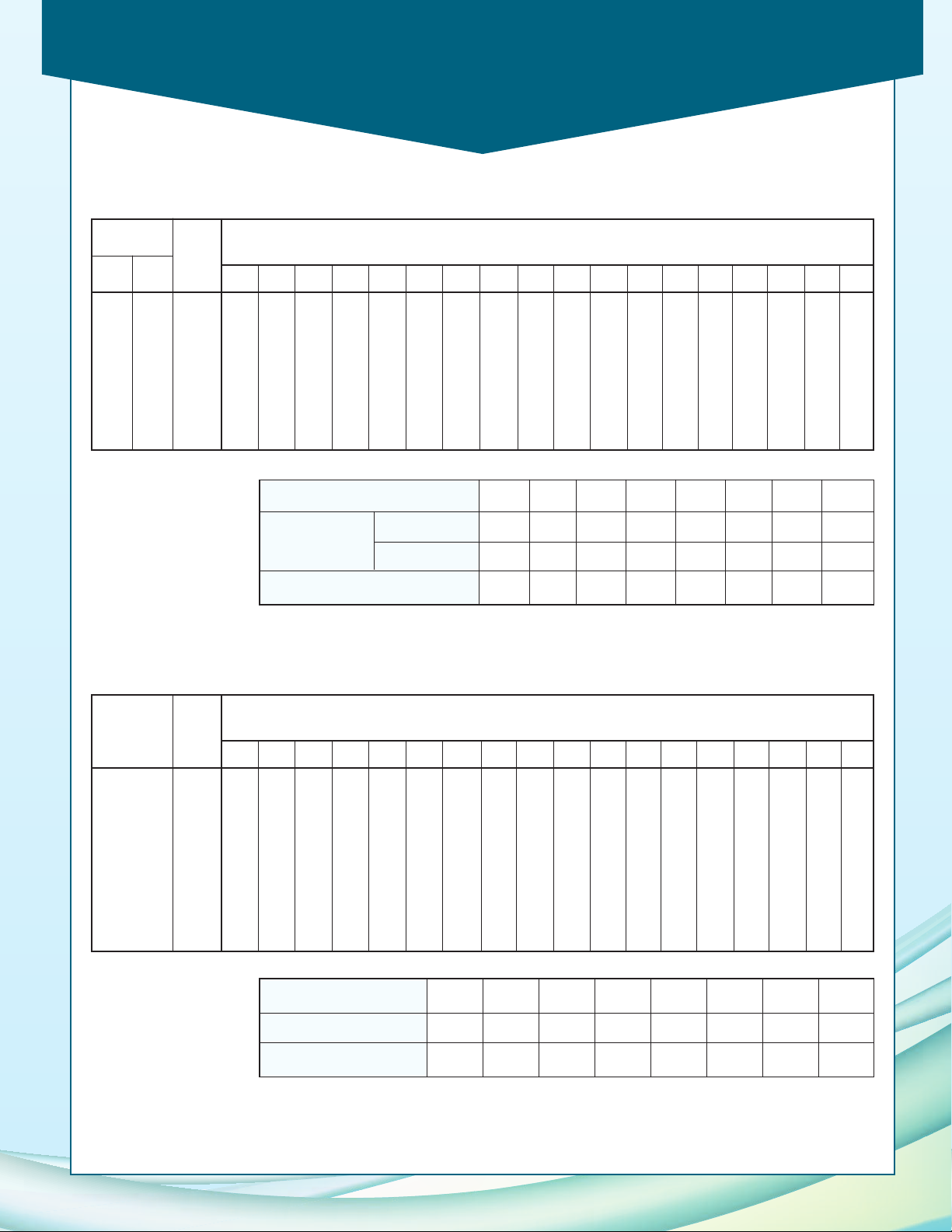
PMC-E Selection Procedure
Table 5 - HCFC-22 and HFC-134a Capacity Factors
ondensing
C
res. psig
P
HCFC-
22
156 95 85 1.05 1.16 1.32 1.43 1.53 1.66 1.83 2.02 2.30 2.64 2.87 3.13 3.46 3.80 ---168 104 90 .90 .98 1.10 1.17 1.24 1.31 1.40 1.52 1.65 1.82 1.93 2.05 2.17 2.30 2.75 3.38 -182 114 95 .78 .85 .93 .98 1.02 1.07 1.12 1.19 1.28 1.37 1.42 1.46 1.52 1.60 1.78 2.02 2.31 2.70
196 124 100 .70 .75 .81 .84 .87 .90 .93 .97 1.02 1.08 1.11 1.14 1.19 1.23 1.33 1.44 1.61 1.80
211 135 105 .63 .66 .70 .72 .75 .77 .80 .83 .87 .91 .93 .95 .97 1.00 1.06 1.13 1.23 1.35
226 146 110 .57 .60 .63 .65 .66 .68 .70 .72 .75 .78 .79 .81 .83 .85 .89 .94 .99 1.05
HFC-
134a
Cond.
Temp.
°F
Wet Bulb Temperature, (°F)
0 55 60 62 64 66 68 70 72 74 75 76 77 78 80 82 84 86
5
Suction Temp. °F -20° -10° -0° +10° +20° +30° +40° +50°
Suction Press.
(psig)
HCFC-22 10.1 16.5 24.0 32.8 43.0 54.9 68.5 84.0
HFC-134a -1.8 1.9 6.5 11.9 18.4 26.1 35.0 45.4
Capacity Factor 1.22 1.17 1.13 1.09 1.06 1.03 1.00 0.97
Table 6 - Ammonia (R-717) Capacity Factors
Condensing Cond.
Pres. Temp.
psig °F
152 85 .99 1.09 1.25 1.34 1.44 1.57 1.73 1.91 2.17 2.49 2.71 2.95 3.26 3.59 ---166 90 .84 .93 1.03 1.10 1.16 1.23 1.32 1.42 1.55 1.71 1.81 1.92 2.04 2.16 2.59 3.17 --
181 95 .74 .80 .87 .92 .97 1.01 1.06 1.12 1.21 1.29 1.33 1.38 1.44 1.51 1.68 1.91 2.18 2.55
185 96.3 .72 .78 .85 .89 .93 .97 1.01 1.07 1.14 1.22 1.26 1.30 1.35 1.41 1.56 1.76 2.01 2.33
197 100 .66 .71 .76 .79 .82 .85 .87 .91 .96 1.01 1.04 1.07 1.12 1.15 1.25 1.36 1.52 1.69
214 105 .59 .62 .66 .68 .71 .73 .75 .78 .82 .86 .88 .90 .91 .94 1.00 1.07 1.16 1.27
232 110 .53 .56 .59 .61 .62 .64 .66 .68 .71 .73 .74 .76 .78 .80 .84 .89 .93 .99
50 55 60 62 64 66 68 70 72 74 75 76 77 78 80 82 84 86
Wet Bulb Temperature, (°F)
Suction Temp. °F -30° -20° -10° 0° +10° +20° +30° +40°
Suction Press. (psig) -1.6 3.6 9.0 15.7 23.8 33.5 45.0 58.6
Capacity Factor 1.18 1.14 1.10 1.07 1.03 1.00 0.97 0.95
Note: Consult factory for selections using other refrigerants.
11
Page 12
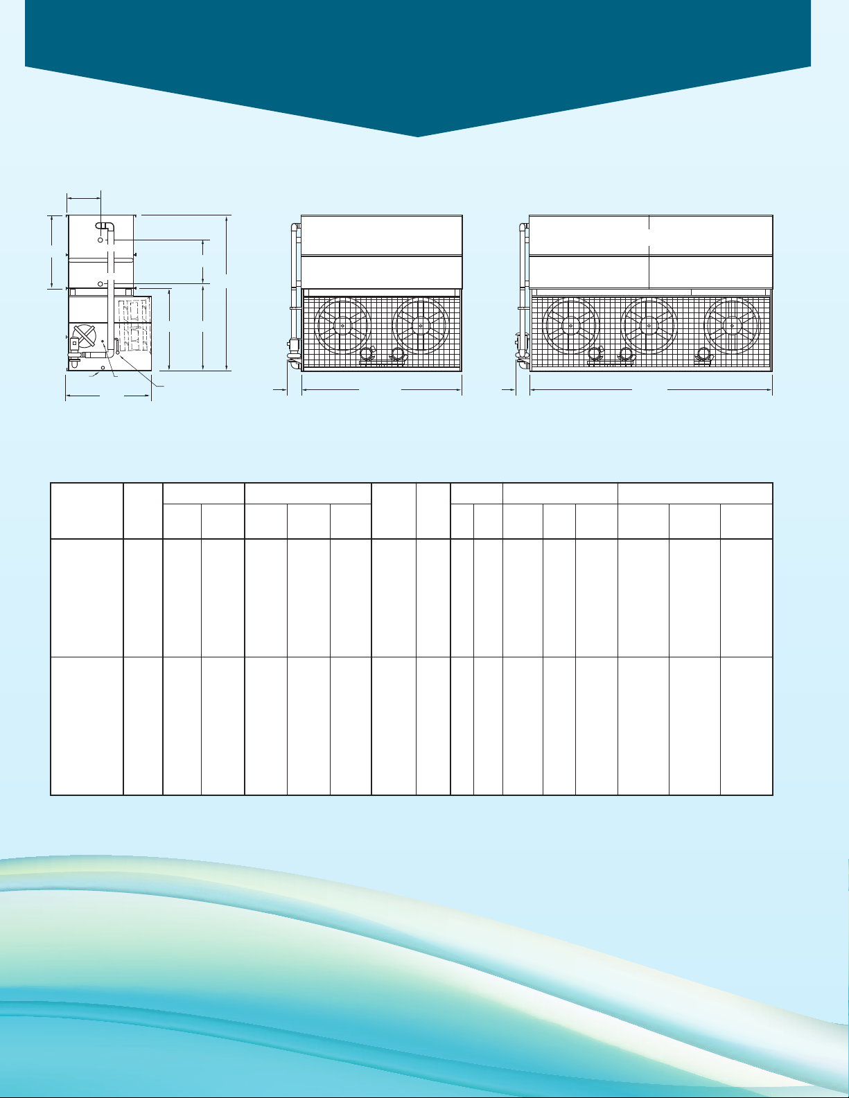
Engineering Dimensions & Data
6’ 4”
1
M.P.T.
MAKE-UP
2 M.P.T.
DRAIN
2 F.P.T.
OVERFLOW
(
2)ACCESS
DOOR
A
74-1/2”H77-5/8”
U
30-3/8"
4
B.F.W. REFRIG. OUT
4 B.F.W. REFRIG. IN
1
1' 11-5/8"12-1/2"
18' 1/8"14"
Models PMC-175E to 375E
PMC-175E to 240E
PMC-250E to 375E
Table 7 Engineering Data
Fans Dimensions (in.)
Weights (lbs)
R-717
Model
Capacity
No. Tons* HP CFM Shipping Section†
PMC-175E 124 (2)5 31,300 8,090 5,220 10,410 165 22 2 345 200 8 9,360 130-3/8 57-3/8 30-3/4
PMC-190E 135 (2)5 34,000 8,090 5,220 10,410 165 22 2 345 200 8 9,360 130-3/8 57-3/8 30-3/4
PMC-210E 149 (2)5 33,500 9,050 6,180 11,400 200 28 2 345 200 8 10,350 138-7/8 65-7/8 39-1/4
PMC-220E 156 (2)5 33,000 10,050 7,180 12,440 240 33 2 345 200 8 11,390 147-3/8 74-3/8 47-3/4
PMC-235E 167 (2)7.5 36,600 9,150 6,180 11,500 200 28 2 345 200 8 10,450 138-7/8 65-7/8 39-1/4
PMC-240E 170 (2)7.5 35,500 10,150 7,180 12,540 240 33 2 345 200 8 11,490 147-3/8 74-3/8 47-3/4
PMC-250E 177 (3)5 54,000 10,570 6,210 13,990 185 25 3 515 260 10 12,040 121-7/8 48-7/8 22-1/4
PMC-275E 195 (3)5 48,500 12,080 7,720 15,560 240 33 3 515 260 10 13,600 130-3/8 57-3/8 30-3/4
PMC-295E 209 (3)5 51,900 12,080 7,720 15,560 240 33 3 515 260 10 13,600 130-3/8 57-3/8 30-3/4
PMC-325E 230 (3)5 50,900 13,530 9,170 17,070 300 41 3 515 260 10 15,110 138-7/8 65-7/8 39-1/4
PMC-335E 238 (3)5 50,300 15,030 10,670 18,630 360 49 3 515 260 10 16,670 147-3/8 74-3/8 47-3/4
PMC-360E 255 (3)7.5 57,000 13,690 9,170 17,230 300 41 3 515 260 10 15,270 138-7/8 65-7/8 39-1/4
PMC-375E 266 (3)7.5 56,300 15,190 10,670 18,790 360 49 3 515 260 10 16,830 147-3/8 74-3/8 47-3/4
†
Refrigerant
Operating
Heaviest Charge
Operating
lbs.*** ft3HP GPM Req’d** Size
Spray Pump Remote Sump
Coil
Volume
Gallons Conn.
Operating
Weight
Height Upper Coil
HUA
* Tons at standard conditions: 96.3°F condensing, 20°F suction and 78°F W.B.
** Gallons shown is water in suspension in unit and piping. Allow for additional water in bottom of remote sump to cover pump suction and strainer during operation.
(12” would normally be sufficient.)
† Heaviest section is the upper coil section. When 5.12 seismic design is required consult the factory for specific weights.
*** Refrigerant charge is shown for R-717. Multiply by 1.93 for R-22 and 1.98 for R-134a.
Dimensions are subject to change. Do not use for pre-fabrication.
12
Page 13
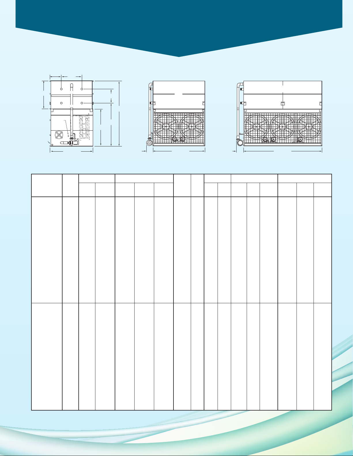
Engineering Dimensions & Data
3
M.P.T.
DRAIN
2
M.P.T.
MAKE-UP
3 F.P.T.
O
VERFLOW
(2)ACCESS
DOOR
A
119”
1
03-1/4”
H
U
57”
30-3/8”
9’ 9-3/4”
(
2)4 B.F.W. REFRIG. OUT
(
2)4 B.F.W. REFRIG. IN
11' 11-3/4"18"
18
’ 1/8”20-5/8”
Models PMC-332E to 792E
PMC-332E
PMC-503E to 792E
to
530E
Table 8 Engineering Data
Weights (lbs)†
Heaviest
Refrigerant
Operating
Charge Volume
Model
R-717
Fans
Capacity
No. Tons* HP CFM Shipping Section† Operating lbs.*** ft3HP GPM
PMC-332E 235 (2) 5 61,000 12,870 8,590 16,950 250 34 5 685 500 10 16,270 163-3/8 61 22-1/4
PMC-362E 257 (2) 5 60,100 14,840 10,560 19,000 325 44 5 685 500 10 18,320 171-7/8 69-1/2 30-3/4
PMC-369E 262 (2) 7.5 70,000 12,970 8,590 17,050 250 34 5 685 500 10 16,370 163-3/8 61 22-1/4
PMC-386E 274 (2) 5 59,200 16,700 12,420 20,940 405 55 5 685 500 10 20,260 180-3/8 78 39-1/4
PMC-397E 282 (2) 10 77,200 13,000 8,590 17,080 250 34 5 685 500 10 16,400 163-3/8 61 22-1/4
PMC-400E 284 (2) 7.5 69,000 14,940 10,560 19,100 325 44 5 685 500 10 18,420 171-7/8 69-1/2 30-3/4
PMC-411E 291 (2) 5 58,400 18,650 14,370 22,960 480 66 5 685 500 10 22,280 188-7/8 86-1/2 47-3/4
PMC-426E 302 (2) 7.5 67,900 16,800 12,420 21,040 405 55 5 685 500 10 20,360 180-3/8 78 39-1/4
PMC-428E 304 (2) 15 88,700 13,260 8,590 17,340 250 34 5 685 500 10 16,660 163-3/8 61 22-1/4
PMC-431E 306 (2) 10 76,000 14,970 10,560 19,130 325 44 5 685 500 10 18,450 171-7/8 69-1/2 30-3/4
PMC-453E 321 (2) 7.5 66,900 18,750 14,370 23,060 480 66 5 685 500 10 22,380 188-7/8 86-1/2 47-3/4
PMC-457E 324 (2) 10 74,900 16,830 12,420 21,070 405 55 5 685 500 10 20,390 180-3/8 78 39-1/4
PMC-464E 329 (2) 15 87,400 15,230 10,560 19,390 325 44 5 685 500 10 18,710 171-7/8 69-1/2 30-3/4
PMC-481E 341 (2) 10 73,800 18,780 14,370 23,090 480 66 5 685 500 10 22,410 188-7/8 86-1/2 47-3/4
PMC-491E 348 (2) 10 72,700 21,130 16,720 25,520 560 76 5 685 500 10 24,840 188-7/8 86-1/2 47-3/4
PMC-492E 349 (2) 15 86,100 17,090 12,420 21,330 405 55 5 685 500 10 20,650 180-3/8 78 39-1/4
PMC-519E 368 (2) 15 84,800 19,040 14,370 23,350 480 66 5 685 500 10 22,670 188-7/8 86-1/2 47-3/4
PMC-530E 376 (2) 15 83,500 21,390 16,720 25,780 560 76 5 685 500 10 25,100 188-7/8 86-1/2 47-3/4
PMC-503E 357 (3) 5 91,800 19,590 12,580 25,910 365 50 7.5 1,030 620 12 23,710 163-3/8 61 22-1/4
PMC-546E 387 (3) 5 90,500 22,520 15,510 28,960 485 66 7.5 1,030 620 12 26,760 171-7/8 69-1/2 30-3/4
PMC-558E 396 (3) 7.5 105,300 19,750 12,580 26,070 365 50 7.5 1,030 620 12 23,870 163-3/8 61 22-1/4
PMC-579E 411 (3) 5 89,100 25,340 18,330 31,890 600 82 7.5 1,030 620 12 29,690 180-3/8 78 39-1/4
PMC-596E 423 (3) 10 116,100 19,800 12,580 26,120 365 50 7.5 1,030 620 12 23,920 163-3/8 61 22-1/4
PMC-602E 427 (3) 5 87,800 28,270 21,260 34,940 720 98 7.5 1,030 620 12 32,740 188-7/8 86-1/2 47-3/4
PMC-605E 429 (3) 7.5 103,800 22,680 15,510 29,120 485 66 7.5 1,030 620 12 26,920 171-7/8 69-1/2 30-3/4
PMC-636E 451 (3) 15 133,500 20,190 12,580 26,510 365 50 7.5 1,030 620 12 24,310 163-3/8 61 22-1/4
PMC-641E 455 (3) 7.5 102,200 25,500 18,330 32,050 600 82 7.5 1,030 620 12 29,850 180-3/8 78 39-1/4
PMC-645E 457 (3) 10 114,400 22,730 15,510 29,170 485 66 7.5 1,030 620 12 26,970 171-7/8 69-1/2 30-3/4
PMC-668E 474 (3) 7.5 100,700 28,430 21,260 35,100 720 98 7.5 1,030 620 12 32,900 188-7/8 86-1/2 47-3/4
PMC-690E 489 (3) 15 131,500 23,120 15,510 29,560 485 66 7.5 1,030 620 12 27,360 171-7/8 69-1/2 30-3/4
PMC-691E 490 (3) 10 112,700 25,550 18,330 32,100 600 82 7.5 1,030 620 12 29,900 180-3/8 78 39-1/4
PMC-719E 510 (3) 10 111,100 28,480 21,260 35,150 720 98 7.5 1,030 620 12 32,950 188-7/8 86-1/2 47-3/4
PMC-731E 518 (3) 15 129,600 25,940 18,330 32,490 600 82 7.5 1,030 620 12 30,290 180-3/8 78 39-1/4
PMC-732E 519 (3) 10 109,400 32,010 24,790 38,800 835 114 7.5 1,030 620 12 36,600 188-7/8 86-1/2 47-3/4
PMC-778E 552 (3) 15 127,600 28,870 21,260 35,540 720 98 7.5 1,030 620 12 33,340 188-7/8 86-1/2 47-3/4
PMC-792E 562 (3) 15 125,700 32,400 24,790 39,190 835 114 7.5 1,030 620 12 36,990 188-7/8 86-1/2 47-3/4
* Tons at standard conditions: 96.3°F condensing, 20°F suction and 78°F W.B.
** Gallons shown is water in suspension in unit and piping. Allow for additional water in bottom of remote sump to cover pump suction and strainer during operation.
(12” would normally be sufficient.)
† Heaviest section is the upper coil section. When 5.12 seismic design is required consult the factory for specific weights.
*** Refrigerant charge is shown for R-717. Multiply by 1.93 for R-22 and 1.98 for R-134a.
Dimensions are subject to change. Do not use for pre-fabrication.
Spray Pump Remote Sump
Coil
Gallons Conn.
Req’d**
Dimensions (in.)
Operating
Height Upper Coil
Size Weight HUA
13
Page 14
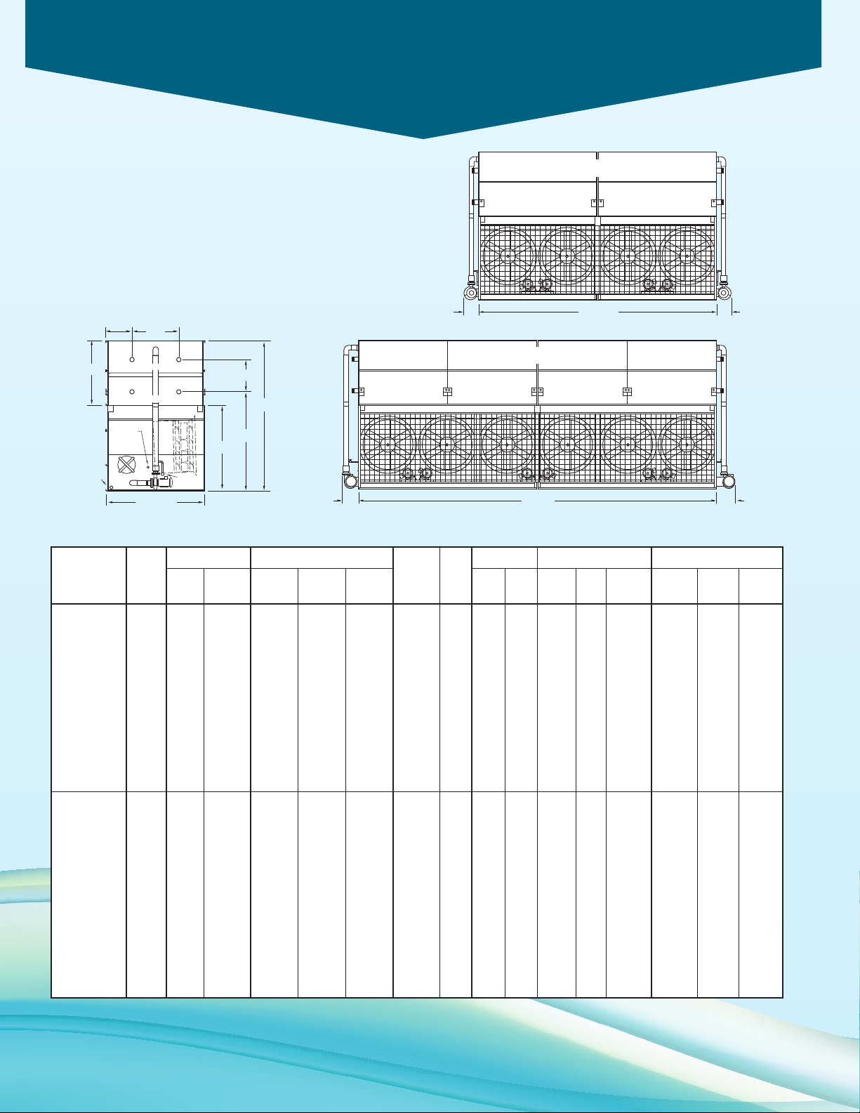
Engineering Dimensions & Data
3 M.P.T.
DRAIN
2 M.P.T.
MAKE-UP
3 F.P.T.
OVERFLOW
(2)ACCESS
DOOR
A
1
19”
103-1/4”
H
U
57”
30-3/8”
9’ 9-3/4”
(2)4 B.F.W. REFRIG. OUT
(2)4 B.F.W. REFRIG. IN
24
’ 7/8”18” 16-3/8”
36’ 2”20-5/8” 23-5/8”
Models PMC-725E to 1586E
PMC-725E to 1056E
PMC-1006E to 1586E
Table 9 Engineering Data
Weights (lbs)†
Heaviest
Refrigerant
Operating
Charge
Model
R-717
Fans
Capacity
No. Tons* HP CFM Shipping Section† Operating lbs.*** ft3HP GPM
PMC-725E 514 (4) 5 120,200 29,930 10,360 38,610 650 89 (2) 5 1,370 930 12 36,470 171-7/8 69-1/2 30-3/4
PMC-735E 521 (4) 7.5 140,000 26,000 9,420 34,530 495 68 (2) 5 1,370 930 12 32,390 163-3/8 61 22-1/4
PMC-772E 548 (4) 5 118,500 33,850 12,320 42,690 805 110 (2) 5 1,370 930 12 40,550 180-3/8 78 39-1/4
PMC-801E 568 (4) 7.5 137,900 30,140 10,360 38,820 650 89 (2) 5 1,370 930 12 36,680 171-7/8 69-1/2 30-3/4
PMC-853E 605 (4) 7.5 135,900 34,060 12,320 42,900 805 110 (2) 5 1,370 930 12 40,760 180-3/8 78 39-1/4
PMC-863E 612 (4) 10 152,100 30,210 10,360 38,890 650 89 (2) 5 1,370 930 12 36,750 171-7/8 69-1/2 30-3/4
PMC-888E 630 (4) 7.5 133,900 38,160 14,370 47,150 960 131 (2) 5 1,370 930 12 45,010 188-7/8 86-1/2 47-3/4
PMC-929E 659 (4) 15 174,800 30,730 10,360 39,410 650 89 (2) 5 1,370 930 12 37,270 171-7/8 69-1/2 30-3/4
PMC-962E 682 (4) 10 147,600 38,230 14,370 47,220 960 131 (2) 5 1,370 930 12 45,080 188-7/8 86-1/2 47-3/4
PMC-980E 695 (4) 10 145,400 42,930 16,720 52,080 1,115 152 (2) 5 1,370 930 12 49,940 188-7/8 86-1/2 47-3/4
PMC-983E 697 (4) 15 172,200 34,650 12,320 43,490 805 110 (2) 5 1,370 930 12 41,350 180-3/8 78 39-1/4
PMC-1038E 736 (4) 15 169,600 38,750 14,370 47,740 960 131 (2) 5 1,370 930 12 45,600 188-7/8 86-1/2 47-3/4
PMC-1056E 749 (4) 15 167,100 43,450 16,720 52,600 1,115 152 (2) 5 1,370 930 12 50,460 188-7/8 86-1/2 47-3/4
PMC-1006E 713 (6) 5 183,700 37,680 13,280 50,650 735 100 (2) 7.5 2,060 1,400 14 47,370 163-3/8 61 22-1/4
PMC-1088E 772 (6) 5 181,000 43,800 15,260 57,000 970 132 (2) 7.5 2,060 1,400 14 53,730 171-7/8 69-1/2 30-3/4
PMC-1116E 791 (6) 7.5 210,600 37,990 13,590 50,960 735 100 (2) 7.5 2,060 1,400 14 47,680 163-3/8 61 22-1/4
PMC-1148E 814 (6) 5 178,300 49,700 18,210 63,140 1,205 164 (2) 7.5 2,060 1,400 14 59,860 180-3/8 78 39-1/4
PMC-1189E 843 (6) 10 232,300 38,090 13,690 51,060 735 100 (2) 7.5 2,060 1,400 14 47,780 163-3/8 61 22-1/4
PMC-1211E 859 (6) 7.5 207,500 44,110 15,260 57,310 970 132 (2) 7.5 2,060 1,400 14 54,040 171-7/8 69-1/2 30-3/4
PMC-1275E 904 (6) 7.5 204,500 50,010 18,210 63,450 1,205 164 (2) 7.5 2,060 1,400 14 60,170 180-3/8 78 39-1/4
PMC-1290E 915 (6) 10 228,900 44,210 15,260 57,410 970 132 (2) 7.5 2,060 1,400 14 54,140 171-7/8 69-1/2 30-3/4
PMC-1333E 945 (6) 7.5 201,400 56,110 21,260 69,780 1,435 196 (2) 7.5 2,060 1,400 14 66,500 188-7/8 86-1/2 47-3/4
PMC-1382E 980 (6) 10 225,500 50,110 18,210 63,550 1,205 164 (2) 7.5 2,060 1,400 14 60,270 180-3/8 78 39-1/4
PMC-1438E 1,020 (6) 10 222,100 56,210 21,260 69,880 1,435 196 (2) 7.5 2,060 1,400 14 66,600 188-7/8 86-1/2 47-3/4
PMC-1466E 1,040 (6) 10 218,800 63,270 24,790 77,170 1,670 228 (2) 7.5 2,060 1,400 14 73,900 188-7/8 86-1/2 47-3/4
PMC-1556E 1,104 (6) 15 255,300 56,990 21,260 70,660 1,435 196 (2) 7.5 2,060 1,400 14 67,380 188-7/8 86-1/2 47-3/4
PMC-1586E 1,125 (6) 15 251,500 64,050 24,790 77,950 1,670 228 (2) 7.5 2,060 1,400 14 74,680 188-7/8 86-1/2 47-3/4
* Tons at standard conditions: 96.3°F condensing, 20°F suction and 78°F W.B.
** Gallons shown is water in suspension in unit and piping. Allow for additional water in bottom of remote sump to cover pump suction and strainer during
operation.
(12” would normally be sufficient.)
† Heaviest section is the upper coil section. When 5.12 seismic design is required consult the factory for specific weights.
*** Refrigerant charge is shown for R-717. Multiply by 1.93 for R-22 and 1.98 for R-134a.
14
Dimensions are subject to change. Do not use for pre-fabrication.
Spray Pump Remote Sump
Coil
Volume
Gallons Conn.
Req’d**
Size Weight HUA
Operating
Dimensions (in.)
Height Upper Coil
Page 15
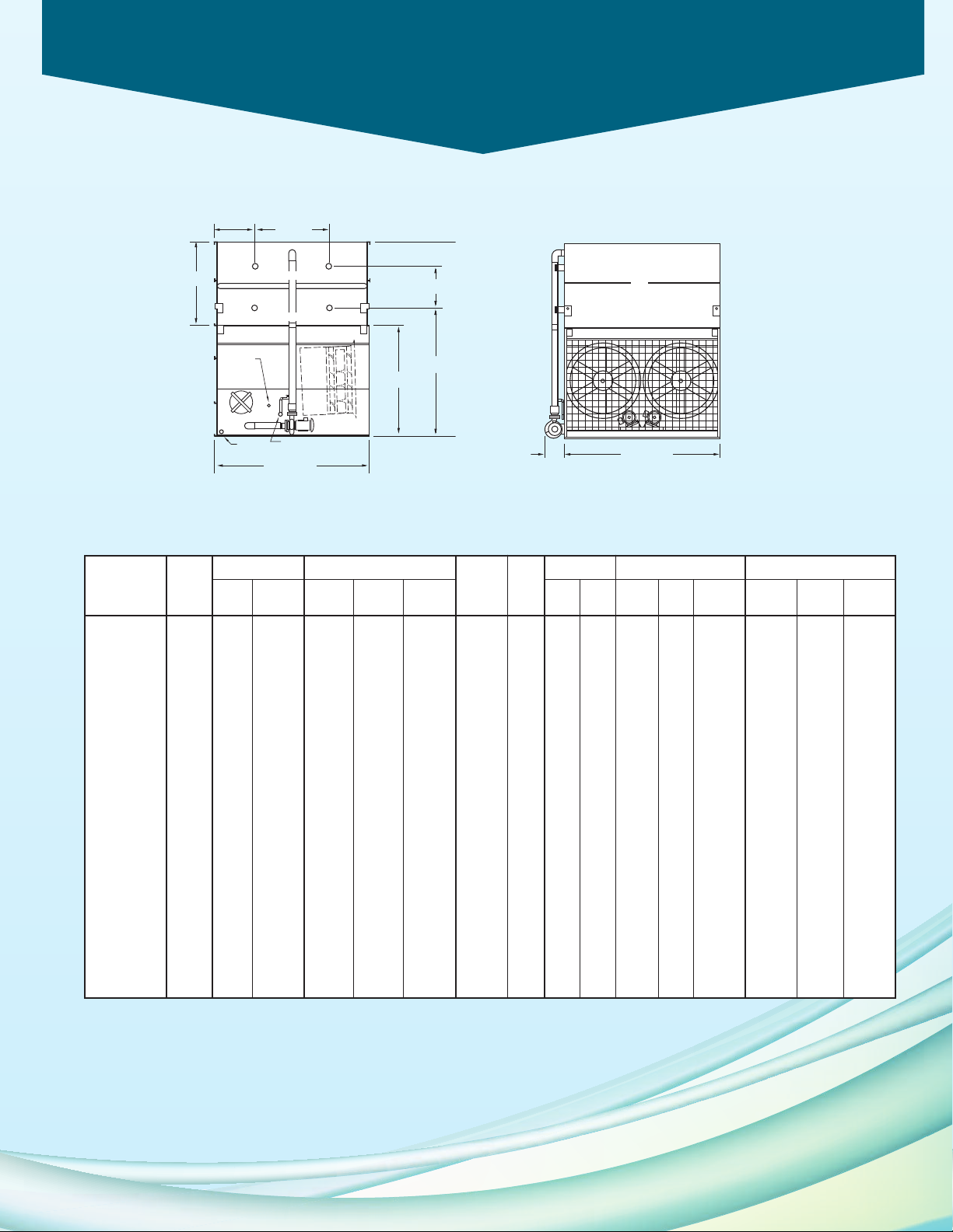
Engineering Dimensions & Data
3 M.P.T.
DRAIN
2 M.P.T.
MAKE-UP
3 F.P.T.
OVERFLOW
(2)ACCESS
DOOR
A
1
19”
103-11/16”
U
68-5/8”
36-3/4”
1
1’ 10-3/8”
(2)4 B.F.W. REFRIG. OUT
(2)4 B.F.W. REFRIG. IN
1
1' 11-3/4"18"
Models PMC-376E to 640E
PMC-376E
to
640E
Table 10 Engineering Data
Weights (lbs)†
Heaviest
Refrigerant
Operating
Charge
Model
R-717
Fans
Capacity
No. Tons* HP CFM Shipping Section† Operating lbs.*** ft3HP GPM
PMC-376E 267 (2) 5 73,523 14,950 9,970 19,990 305 42 5 800 570 10 18,960 163-3/8 61 22-1/4
PMC-408E 289 (2) 5 72,409 17,340 12,360 22,480 400 55 5 800 570 10 21,450 171-7/8 69-1/2 30-3/4
PMC-420E 298 (2) 7.5 79,200 15,050 9,970 20,090 305 42 5 800 570 10 19,060 163-3/8 61 22-1/4
PMC-427E 303 (2) 5 71,480 19,610 14,630 24,840 495 68 5 800 570 10 23,810 180-3/8 78 39-1/4
PMC-450E 319 (2) 10 84,500 15,090 9,970 20,130 305 42 5 800 570 10 19,100 163-3/8 61 22-1/4
PMC-456E 323 (2) 7.5 78,000 17,440 12,360 22,580 400 55 5 800 570 10 21,550 171-7/8 69-1/2 30-3/4
PMC-479E 340 (2) 7.5 77,000 19,710 14,630 24,940 495 68 5 800 570 10 23,910 180-3/8 78 39-1/4
PMC-488E 346 (2) 10 83,200 17,480 12,360 22,620 400 55 5 800 570 10 21,590 171-7/8 69-1/2 30-3/4
PMC-495E 351 (2) 15 97,100 15,350 9,970 20,390 305 42 5 800 570 10 19,360 163-3/8 61 22-1/4
PMC-501E 355 (2) 7.5 75,700 21,940 16,860 27,270 595 81 5 800 570 10 26,240 188-7/8 86-1/2 47-3/4
PMC-513E 364 (2) 10 82,000 19,750 14,630 24,980 495 68 5 800 570 10 23,950 180-3/8 78 39-1/4
PMC-515E 365 (2) 20 100,300 15,470 9,970 20,510 305 42 5 800 570 10 19,480 163-3/8 61 22-1/4
PMC-536E 380 (2) 15 95,600 17,740 12,360 22,880 400 55 5 800 570 10 21,850 171-7/8 69-1/2 30-3/4
PMC-537E 381 (2) 10 80,800 21,980 16,860 27,310 595 81 5 800 570 10 26,280 188-7/8 86-1/2 47-3/4
PMC-545E 387 (2) 10 79,600 24,740 19,620 30,170 690 94 5 800 570 10 29,140 188-7/8 86-1/2 47-3/4
PMC-559E 396 (2) 20 98,700 28,270 21,260 34,940 720 55 5 800 620 10 32,740 171-7/8 69-1/2 30-3/4
PMC-564E 400 (2) 15 94,400 20,010 14,630 25,240 495 68 5 800 570 10 24,210 180-3/8 78 39-1/4
PMC-591E 419 (2) 15 92,800 22,240 16,860 27,570 595 81 5 800 570 10 26,540 188-7/8 86-1/2 47-3/4
PMC-600E 426 (2) 15 91,400 25,000 19,620 30,430 690 94 5 800 570 10 29,400 188-7/8 86-1/2 47-3/4
PMC-601E 426 (2) 20 100,300 20,130 14,630 25,360 495 68 5 800 570 10 24,330 180-3/8 78 39-1/4
PMC-631E 448 (2) 20 98,800 22,360 16,860 27,690 595 81 5 800 570 10 26,660 188-7/8 86-1/2 47-3/4
PMC-640E 454 (2) 20 97,300 25,120 19,620 30,550 690 94 5 800 570 10 29,520 188-7/8 86-1/2 47-3/4
Spray Pump Remote Sump
Coil
Volume
Gallons Conn.
Req’d**
Dimensions (in.)
Operating
Height Upper Coil
Size Weight HUA
* Tons at standard conditions: 96.3°F condensing, 20°F suction and 78°F W.B.
** Gallons shown is water in suspension in unit and piping. Allow for additional water in bottom of remote sump to cover pump suction and strainer during operation.
(12” would normally be sufficient.)
† Heaviest section is the upper coil section. When 5.12 seismic design is required consult the factory for specific weights.
*** Refrigerant charge is shown for R-717. Multiply by 1.93 for R-22 and 1.98 for R-134a.
Dimensions are subject to change. Do not use for pre-fabrication.
15
Page 16
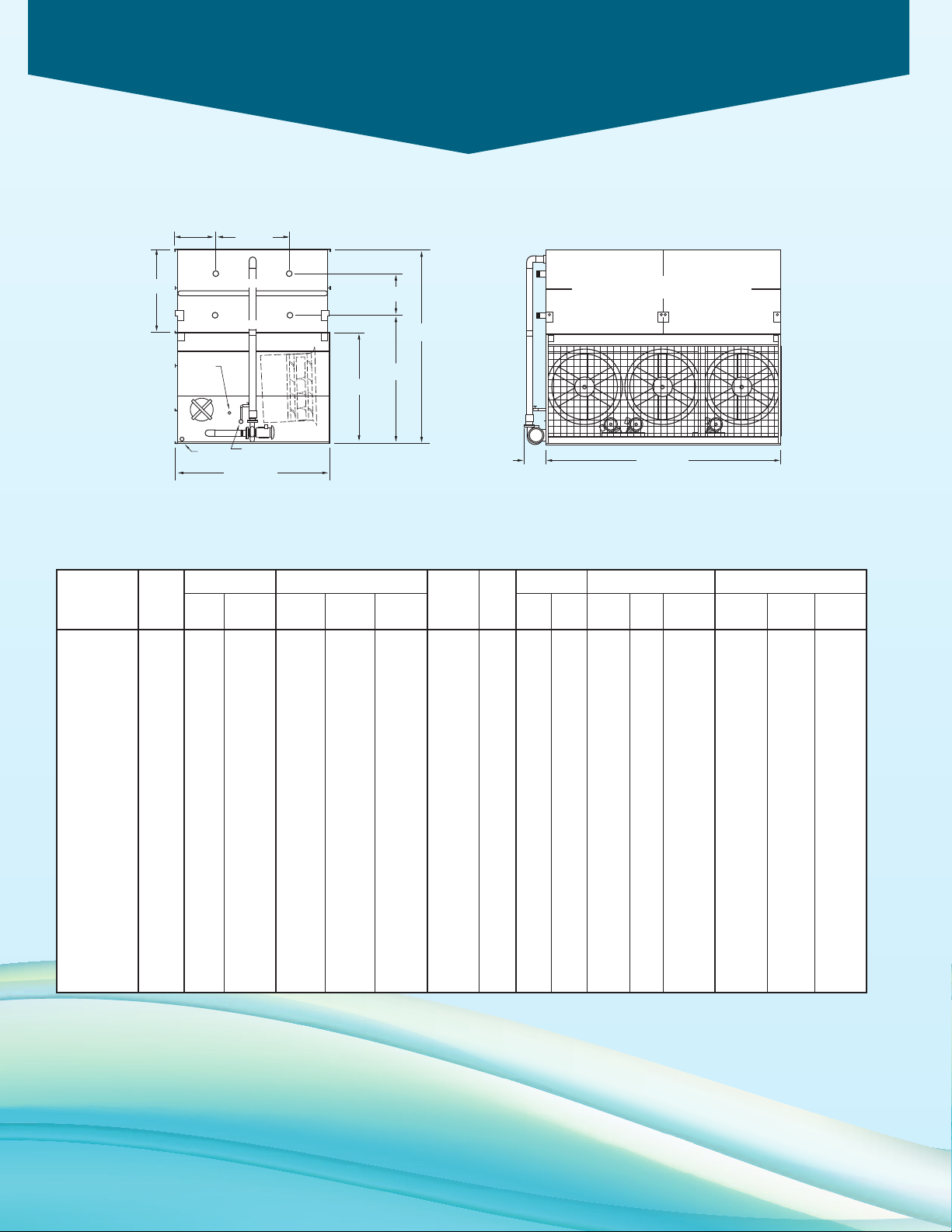
Engineering Dimensions & Data
3 M.P.T.
DRAIN
2 M.P.T.
MAKE-UP
3 F.P.T.
OVERFLOW
(2)ACCESS
DOOR
A
119”
1
03-11/16”
H
U
6
8-5/8”
3
6-3/4”
1
1’ 10-3/8”
(2)4 B.F.W. REFRIG. OUT
(2)4 B.F.W. REFRIG. IN
18
’ 1/8”20-5/8”
Models PMC-568E to 955E
PMC-568E to 955E
Table 11 Engineering Data
Weights (lbs)†
Heaviest
Refrigerant
Operating
Charge
Model
R-717
Fans
Capacity
No. Tons* HP CFM Shipping Section† Operating lbs.*** ft3HP GPM
PMC-568E 403 (3) 5 109,913 22,760 14,920 30,090 450 62 7.5 1,200 740 12 27,430 163-3/8 61 22-1/4
PMC-616E 437 (3) 5 108,335 26,330 18,490 33,810 595 81 7.5 1,200 740 12 31,150 171-7/8 69-1/2 30-3/4
PMC-634E 450 (3) 7.5 118,400 22,920 14,920 30,250 450 62 7.5 1,200 740 12 27,590 163-3/8 61 22-1/4
PMC-647E 459 (3) 5 106,942 29,770 21,930 37,390 740 101 7.5 1,200 740 12 34,730 180-3/8 78 39-1/4
PMC-675E 479 (3) 5 105,178 29,930 10,360 38,610 650 121 7.5 1,200 930 12 36,470 188-7/8 86-1/2 47-3/4
PMC-679E 482 (3) 10 126,300 22,970 14,920 30,300 450 62 7.5 1,200 740 12 27,640 163-3/8 61 22-1/4
PMC-688E 488 (3) 7.5 116,700 26,490 18,490 33,970 595 81 7.5 1,200 740 12 31,310 171-7/8 69-1/2 30-3/4
PMC-723E 513 (3) 7.5 115,200 29,930 21,930 37,550 740 101 7.5 1,200 740 12 34,890 180-3/8 78 39-1/4
PMC-737E 523 (3) 10 124,500 26,540 18,490 34,020 595 81 7.5 1,200 740 12 31,360 171-7/8 69-1/2 30-3/4
PMC-751E 533 (3) 7.5 113,300 33,140 25,140 40,910 885 121 7.5 1,200 740 12 38,250 188-7/8 86-1/2 47-3/4
PMC-774E 549 (3) 10 122,600 29,980 21,930 37,600 740 101 7.5 1,200 740 12 34,940 180-3/8 78 39-1/4
PMC-800E 567 (3) 15 143,000 26,930 18,490 34,410 595 81 7.5 1,200 740 12 31,750 171-7/8 69-1/2 30-3/4
PMC-803E 570 (3) 10 120,800 33,190 25,140 40,960 885 121 7.5 1,200 740 12 38,300 188-7/8 86-1/2 47-3/4
PMC-819E 581 (3) 10 119,000 37,310 29,260 45,220 1,030 140 7.5 1,200 740 12 42,560 188-7/8 86-1/2 47-3/4
PMC-831E 589 (3) 20 147,600 27,120 18,490 34,600 595 81 7.5 1,200 740 12 31,940 171-7/8 69-1/2 30-3/4
PMC-856E 607 (3) 15 141,200 30,370 21,930 37,990 740 101 7.5 1,200 740 12 35,330 180-3/8 78 39-1/4
PMC-889E 630 (3) 15 138,800 33,580 25,140 41,350 885 121 7.5 1,200 740 12 38,690 188-7/8 86-1/2 47-3/4
PMC-894E 634 (3) 20 149,900 30,560 21,930 38,180 740 101 7.5 1,200 740 12 35,520 180-3/8 78 39-1/4
PMC-905E 642 (3) 15 136,700 37,700 29,260 45,610 1,030 140 7.5 1,200 740 12 42,950 188-7/8 86-1/2 47-3/4
PMC-939E 666 (3) 20 147,700 33,770 25,140 41,540 885 121 7.5 1,200 740 12 38,880 188-7/8 86-1/2 47-3/4
PMC-955E 677 (3) 20 145,500 37,890 29,260 45,800 1,030 140 7.5 1,200 740 12 43,140 188-7/8 86-1/2 47-3/4
* Tons at standard conditions: 96.3°F condensing, 20°F suction and 78°F W.B.
** Gallons shown is water in suspension in unit and piping. Allow for additional water in bottom of remote sump to cover pump suction and strainer during operation.
(12” would normally be sufficient.)
† Heaviest section is the upper coil section. When 5.12 seismic design is required consult the factory for specific weights.
*** Refrigerant charge is shown for R-717. Multiply by 1.93 for R-22 and 1.98 for R-134a.
Dimensions are subject to change. Do not use for pre-fabrication.
Spray Pump Remote Sump
Coil
Volume
Gallons Conn.
Req’d**
Dimensions (in.)
Operating
Height Upper Coil
Size Weight HUA
16
Page 17
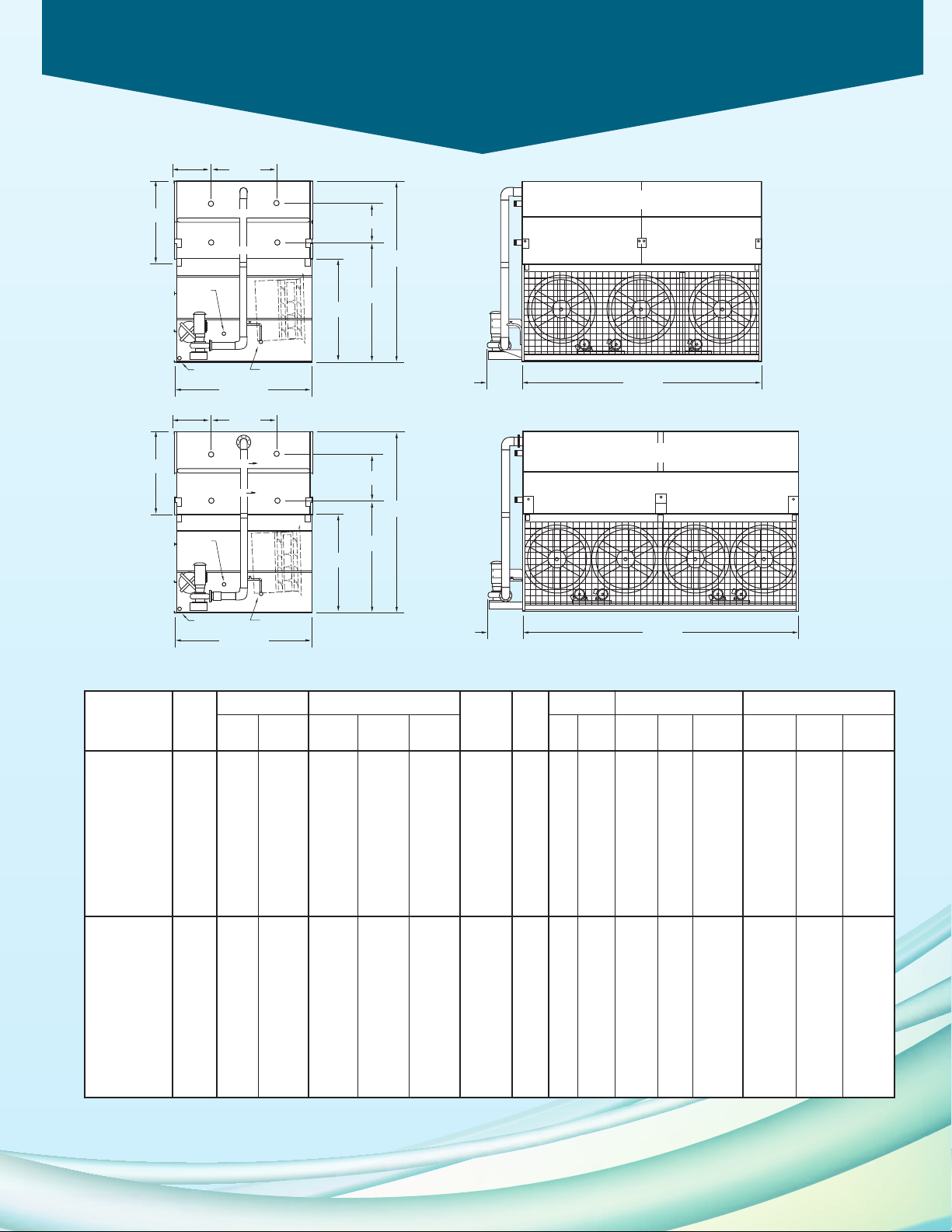
Engineering Dimensions & Data
20
’ 1/4”36-3/8”
3 M.P.T.
DRAIN
3 M.P.T.
MAKE-UP
3 F.P.T.
OVERFLOW
(2)ACCESS
DOOR
A
1
19”
1
03-11/16”
H
U
68-5/8”
3
6-3/4”
1
1’ 10-3/8”
(2)4 B.F.W. REFRIG. OUT
(2)4 B.F.W. REFRIG. IN
24’ 7/8”36-3/8”
3 M.P.T.
DRAIN
3
M.P.T.
M
AKE-UP
3 F.P.T.
OVERFLOW
(2)ACCESS
DOOR
A
117”
103-11/16”
H
U
68-5/8”
3
7-1/4”
11’ 10-3/8”
(
2)4 B.F.W. REFRIG. AMMONIA OUT
(2)4 B.F.W. REFRIG. AMMONIA IN
Models PMC-715E to 1258E
PMC-715E to 1013E
PMC-911E to 1258E
Table 12 Engineering Data
Weights (lbs)†
Heaviest
Refrigerant
Operating
Charge
Model
R-717
Fans Dimensions (in.)
Capacity
No. Tons* HP CFM Shipping Section† Operating lbs.*** f t3HP GPM
PMC-715E 507 (3) 5 111,398 36,680 28,190 45,510 985 134 10 1,400 810 14 42,520 188-7/8 86-1/2 47-3/4
PMC-796E 565 (3) 7.5 120,000 36,840 28,190 45,670 985 134 10 1,400 810 14 42,680 188-7/8 86-1/2 47-3/4
PMC-811E 575 (3) 10 130,000 32,820 24,120 41,490 820 112 10 1,400 810 14 38,500 180-3/8 78 39-1/4
PMC-852E 604 (3) 10 128,000 36,890 28,190 45,720 985 134 10 1,400 810 14 42,730 188-7/8 86-1/2 47-3/4
PMC-895E 635 (3) 15 149,600 33,210 24,120 41,880 820 112 10 1,400 810 14 38,890 180-3/8 78 39-1/4
PMC-940E 667 (3) 15 147,100 37,280 28,190 46,110 985 134 10 1,400 810 14 43,120 188-7/8 86-1/2 47-3/4
PMC-949E 673 (3) 20 158,900 33,400 24,120 42,070 820 112 10 1,400 810 14 39,080 180-3/8 78 39-1/4
PMC-959E 680 (3) 15 144,900 41,930 32,840 50,920 1,145 156 10 1,400 810 14 47,930 188-7/8 86-1/2 47-3/4
PMC-992E 704 (3) 20 156,600 37,470 28,190 46,300 985 134 10 1,400 810 14 43,310 188-7/8 86-1/2 47-3/4
PMC-1013E 718 (3) 20 154,300 42,120 32,840 51,110 1,145 156 10 1,400 810 14 48,120 188-7/8 86-1/2 47-3/4
††
PMC-911E
PMC-954E
PMC-974E
PMC-1002E
PMC-1021E
PMC-1070E
PMC-1071E
PMC-1125E
PMC-1180E
PMC-1201E
PMC-1258E
* Tons at standard conditions: 96.3°F condensing, 20°F suction and 78°F W.B.
** Gallons shown is water in suspension in unit and piping. Allow for additional water in bottom of remote sump to cover pump suction and strainer during operation.
(12” would normally be sufficient.)
† Heaviest section is the upper coil section. When 5.12 seismic design is required consult the factory for specific weights.
*** Refrigerant charge is shown for R-717. Multiply by 1.93 for R-22 and 1.98 for R-134a.
Dimensions are subject to change. Do not use for pre-fabrication.
†† These units are available for Ammonia applications only.
646 (4) 7.5 166,800 33,910 23,710 45,070 790 108 10 1,600 1,080 14 42,270 178-7/8 76-1/2 38-3/4
††
677 (4) 7.5 164,300 38,500 28,300 49,850 985 134 10 1,600 1,080 14 47,050 188-7/8 86-1/2 48-3/4
††
691 (4) 10 166,800 33,970 23,710 45,130 790 108 10 1,600 1,080 14 42,330 178-7/8 76-1/2 38-3/4
††
711 (4) 7.5 161,900 43,360 33,160 54,910 1,180 161 10 1,600 1,080 14 52,110 198-7/8 96-1/2 58-3/4
††
724 (4) 10 164,300 38,560 28,300 49,910 985 134 10 1,600 1,080 14 47,110 188-7/8 86-1/2 48-3/4
††
759 (4) 10 161,900 43,420 33,160 54,970 1,180 161 10 1,600 1,080 14 52,170 198-7/8 96-1/2 58-3/4
††
760 (4) 15 191,600 34,500 23,710 45,660 790 108 10 1,600 1,080 14 42,860 178-7/8 76-1/2 38-3/4
††
798 (4) 15 189,100 39,090 28,300 50,440 985 134 10 1,600 1,080 14 47,640 188-7/8 86-1/2 48-3/4
††
837 (4) 15 186,000 43,950 33,160 55,500 1,180 161 10 1,600 1,080 14 52,700 198-7/8 96-1/2 58-3/4
††
††
852 (4) 20 200,900 39,340 28,300 50,690 985 134 10 1,600 1,080 14 47,890 188-7/8 86-1/2 48-3/4
892 (4) 20 197,900 44,200 33,160 55,750 1,180 161 10 1,600 1,080 14 52,950 198-7/8 96-1/2 58-3/4
Spray Pump Remote Sump
Coil
Volume
Gallons Conn.
Req’d**
Operating
Height Upper Coil
Size Weight HUA
17
Page 18
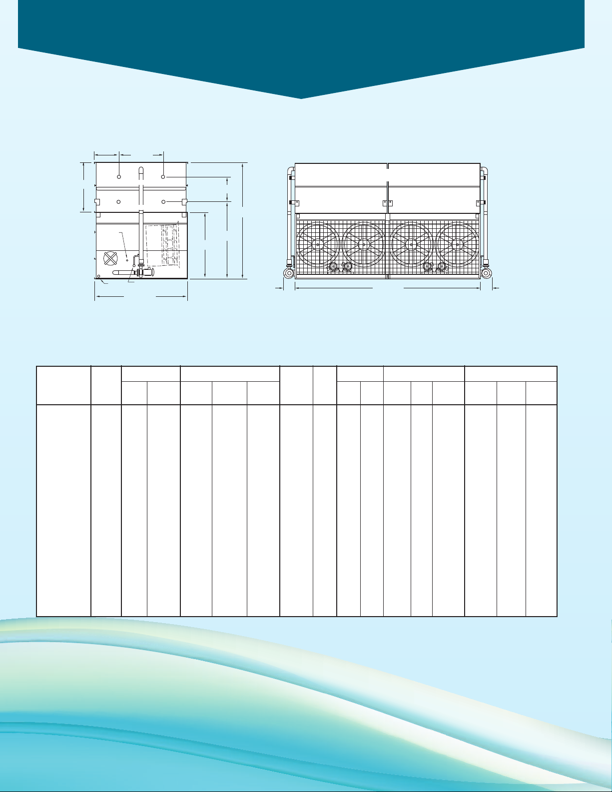
Engineering Dimensions & Data
3 M.P.T.
DRAIN
2 M.P.T.
MAKE-UP
3 F.P.T.
OVERFLOW
(
2)ACCESS
D
OOR
A
1
19”
1
03-11/16”
H
U
68-5/8”
3
6-3/4”
1
1’ 10-3/8”
(2)4 B.F.W. REFRIG. OUT
(2)4 B.F.W. REFRIG. IN
24’ 7/8”18” 16-3/8”
Models PMC-752E to 1286E
PMC-752E to 1286E
Table 13 Engineering Data
Weights (lbs)†
Heaviest
Refrigerant
Operating
Charge
Model
R-717
Fans Dimensions (in.)
Capacity
No. Tons* HP CFM Shipping Section† Operating lbs.*** ft3HP GPM
PMC-752E 533 (4) 5 147,046 29,200 9,920 39,570 610 83 (2) 5 1,600 1,080 14 36,770 163-3/8 61 22-1/4
PMC-816E 579 (4) 5 144,910 34,220 12,150 44,790 805 109 (2) 5 1,600 1,080 14 41,990 171-7/8 69-1/2 30-3/4
PMC-840E 596 (4) 7.5 158,400 29,410 10,130 39,780 610 83 (2) 5 1,600 1,080 14 36,980 163-3/8 61 22-1/4
PMC-900E 638 (4) 10 169,000 29,480 10,200 39,850 610 83 (2) 5 1,600 1,080 14 37,050 163-3/8 61 22-1/4
PMC-913E 648 (4) 7.5 156,100 34,430 12,150 45,000 805 109 (2) 5 1,600 1,080 14 42,200 171-7/8 69-1/2 30-3/4
PMC-956E 678 (4) 7.5 154,000 39,190 14,530 49,950 995 135 (2) 5 1,600 1,080 14 47,150 180-3/8 78 39-1/4
PMC-976E 692 (4) 10 166,500 34,500 12,150 45,070 805 109 (2) 5 1,600 1,080 14 42,270 171-7/8 69-1/2 30-3/4
PMC-989E 701 (4) 15 194,200 30,000 10,720 40,370 610 83 (2) 5 1,600 1,080 14 37,570 163-3/8 61 22-1/4
PMC-1004E 712 (4) 7.5 151,500 43,850 16,860 54,800 1,185 161 (2) 5 1,600 1,080 14 52,000 188-7/8 86-1/2 47-3/4
PMC-1024E 726 (4) 10 164,000 39,260 14,530 50,020 995 135 (2) 5 1,600 1,080 14 47,220 180-3/8 78 39-1/4
PMC-1072E 760 (4) 10 161,600 43,920 16,860 54,870 1,185 161 (2) 5 1,600 1,080 14 52,070 188-7/8 86-1/2 47-3/4
PMC-1073E 761 (4) 15 191,300 35,020 12,150 45,590 805 109 (2) 5 1,600 1,080 14 42,790 171-7/8 69-1/2 30-3/4
PMC-1117E 792 (4) 20 197,400 35,270 12,150 45,840 805 109 (2) 5 1,600 1,080 14 43,040 171-7/8 69-1/2 30-3/4
PMC-1127E 799 (4) 15 188,800 39,780 14,530 50,540 995 135 (2) 5 1,600 1,080 14 47,740 180-3/8 78 39-1/4
PMC-1182E 838 (4) 15 185,700 44,440 16,860 55,390 1,185 161 (2) 5 1,600 1,080 14 52,590 188-7/8 86-1/2 47-3/4
PMC-1203E 853 (4) 20 200,500 40,030 14,530 50,790 995 135 (2) 5 1,600 1,080 14 47,990 180-3/8 78 39-1/4
PMC-1205E 855 (4) 15 182,900 49,960 19,620 61,100 1,375 188 (2) 5 1,600 1,080 14 58,300 188-7/8 86-1/2 47-3/4
PMC-1261E 894 (4) 20 197,600 44,690 16,860 55,640 1,185 161 (2) 5 1,600 1,080 14 52,840 188-7/8 86-1/2 47-3/4
PMC-1286E 912 (4) 20 194,600 50,210 19,620 61,350 1,375 188 (2) 5 1,600 1,080 14 58,550 188-7/8 86-1/2 47-3/4
* Tons at standard conditions: 96.3°F condensing, 20°F suction and 78°F W.B.
** Gallons shown is water in suspension in unit and piping. Allow for additional water in bottom of remote sump to cover pump suction and strainer during operation.
(12” would normally be sufficient.)
† Heaviest section is the upper coil section. When 5.12 seismic design is required consult the factory for specific weights.
†† Heaviest section is the lower basin section.
*** Refrigerant charge is shown for R-717. Multiply by 1.93 for R-22 and 1.98 for R-134a.
Dimensions are subject to change. Do not use for pre-fabrication.
Spray Pump Remote Sump
Coil
Volume
Gallons Conn.
Req’d**
Operating
Height Upper Coil
Size Weight HUA
18
Page 19
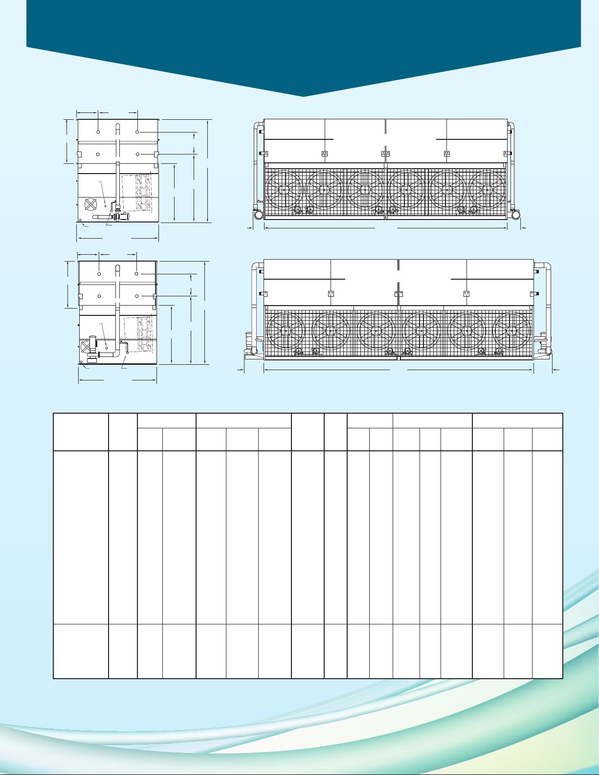
Engineering Dimensions & Data
36’ 2”20-5/8” 23-5/8”
3 M.P.T.
DRAIN
2 M.P.T.
MAKE-UP
3 F.P.T.
OVERFLOW
(2)ACCESS
DOOR
A
119”
103-11/16”
H
U
68-5/8”
36-3/4”
11’ 10-3/8”
(2)4 B.F.W. REFRIG. OUT
(2)4 B.F.W. REFRIG. IN
40’ 2” 32-3/4”36-3/8”
3 M.P.T.
DRAIN
3 M.P.T.
MAKE-UP
3 F.P.T.
OVERFLOW
(2)ACCESS
DOOR
A
119”
103-11/16”
H
U
6
8-5/8”
36-3/4”
11’ 10-3/8”
(2)4 B.F.W. REFRIG. OUT
(2)4 B.F.W. REFRIG. IN
Models PMC-1137E to 2019E
MC-1137E to 1911E
P
PMC-1705E to 2019E
Table 14 Engineering Data
Weights (lbs)†
Heaviest
Refrigerant
Operating
Charge
Model
R-717
Fans Dimensions (in.)
Capacity
No. Tons* HP CFM Shipping Section† Operating lbs.*** ft3HP GPM
PMC-1137E 806 (6) 5 219,826 43,450 14,510 58,860 905 123 (2) 7.5 2,400 1,460 16 53,210 163-3/8 61 22-1/4
PMC-1269E 900 (6) 7.5 236,800 43,770 14,750 59,180 905 123 (2) 7.5 2,400 1,460 16 53,530 163-3/8 61 22-1/4
PMC-1296E 919 (6) 5 213,792 58,010 21,790 74,000 1,480 202 (2) 7.5 2,400 1,460 16 68,340 180-3/8 78 39-1/4
PMC-1358E 963 (6) 10 252,600 43,860 14,840 59,270 905 123 (2) 7.5 2,400 1,460 16 53,620 163-3/8 61 22-1/4
PMC-1376E 976 (6) 7.5 233,300 51,170 18,210 66,870 1,195 163 (2) 7.5 2,400 1,460 16 61,220 171-7/8 69-1/2 30-3/4
PMC-1446E 1,026 (6) 7.5 230,300 58,330 21,790 74,320 1,480 202 (2) 7.5 2,400 1,460 16 68,660 180-3/8 78 39-1/4
PMC-1473E 1,045 (6) 10 248,900 51,260 18,210 66,960 1,195 163 (2) 7.5 2,400 1,460 16 61,310 171-7/8 69-1/2 30-3/4
PMC-1549E 1,099 (6) 10 245,200 58,420 21,790 74,410 1,480 202 (2) 7.5 2,400 1,460 16 68,750 180-3/8 78 39-1/4
PMC-1599E 1,134 (6) 15 286,000 52,050 18,210 67,750 1,195 163 (2) 7.5 2,400 1,460 16 62,100 171-7/8 69-1/2 30-3/4
PMC-1625E 1,152 (6) 10 241,600 65,120 25,140 81,400 1,770 241 (2) 7.5 2,400 1,460 16 75,740 188-7/8 86-1/2 47-3/4
PMC-1712E 1,214 (6) 15 282,300 59,210 21,790 75,200 1,480 202 (2) 7.5 2,400 1,460 16 69,540 180-3/8 78 39-1/4
PMC-1776E 1,260 (6) 15 277,600 65,910 25,140 82,190 1,770 241 (2) 7.5 2,400 1,460 16 76,530 188-7/8 86-1/2 47-3/4
PMC-1788E 1,268 (6) 20 299,800 59,590 21,790 75,580 1,480 202 (2) 7.5 2,400 1,460 16 69,920 180-3/8 78 39-1/4
PMC-1811E 1,284 (6) 15 273,400 74,150 29,260 90,720 2,060 281 (2) 7.5 2,400 1,460 16 85,060 188-7/8 86-1/2 47-3/4
PMC-1877E 1,331 (6) 20 295,400 66,290 25,140 82,570 1,770 241 (2) 7.5 2,400 1,460 16 76,910 188-7/8 86-1/2 47-3/4
PMC-1911E 1,355 (6) 20 291,000 74,530 29,260 91,100 2,060 281 (2) 7.5 2,400 1,460 16 85,440 188-7/8 86-1/2 47-3/4
PMC-1705E 1,209 (6) 10 256,100 72,920 28,390 90,850 1,965 268 (2) 10 2,800 1,630 16 84,620 188-7/8 86-1/2 47-3/4
PMC-1879E 1,333 (6) 15 294,300 73,710 28,390 91,640 1,965 268 (2) 10 2,800 1,630 16 85,410 188-7/8 86-1/2 47-3/4
PMC-1913E 1,357 (6) 15 289,900 83,010 33,040 101,260 2,290 312 (2) 10 2,800 1,630 16 95,030 188-7/8 86-1/2 47-3/4
PMC-1985E 1,408 (6) 20 313,100 74,090 28,390 92,020 1,965 268 (2) 10 2,800 1,630 16 85,790 188-7/8 86-1/2 47-3/4
PMC-2019E 1,432 (6) 20 308,400 83,390 33,040 101,640 2,290 312 (2) 10 2,800 1,630 16 95,410 188-7/8 86-1/2 47-3/4
* Tons at standard conditions: 96.3°F condensing, 20°F suction and 78°F W.B.
** Gallons shown is water in suspension in unit and piping. Allow for additional water in bottom of remote sump to cover pump suction and strainer during operation.
(12” would normally be sufficient.)
† Heaviest section is the upper coil section. When 5.12 seismic design is required consult the factory for specific weights.
†† Heaviest section is the lower basin section.
*** Refrigerant charge is shown for R-717. Multiply by 1.93 for R-22 and 1.98 for R-134a.
Dimensions are subject to change. Do not use for pre-fabrication.
Spray Pump Remote Sump
Coil
Volume
Gallons Conn.
Req’d**
Operating
Size Weight HUA
Height Upper Coil
19
Page 20
Optional Equipment
E
X
C
L
U
S
I
V
E
W
A
R
R
A
N
T
Y
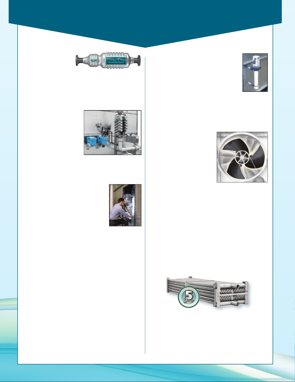
Pulse~Pure
®
Pulse~Pure®is an
environmentally sensitive
non-chemical water treatment system for evaporative
condensers. Developed by EVAPCO, Pulse~Pure
alternative to chemical water treatment programs. Utilizing
pulse-power technology Pulse~Pure
reatment that is environmentally safe.
t
®
provides chemical-free
®
offers an
Smart Shield®Solid Chemistry Water
Treatment System
EVAPCO's SmartShield®solid
chemistry water treatment
system is an innovative
solution to conventional
liquid chemical programs.
SmartSheild
®
was developed
specifically for evaporative
condensers and closed
circuit coolers. The system
comes factory mounted and includes all the components
required for an effective water treatment system. Solid
products eliminate the potential for liquid spills making it easier
and safer to use. Controlled release chemistry provides
uniform treatment over a 30 day period.
Oversized Access Door
For enhanced basin accessibility, the
Oversized Access Door option enables
maintenance personnel to quickly and
easily enter the basin for float valve
adjustment and unit inspection.
Self Supporting Service
Platforms
Condensers are available with self-supporting service platforms
that include access ladders which are designed for easy field
installation. This option offers significant savings in comparison
to field constructed, externally supported catwalks. The Evapco
service platform option may be installed on either side, or the
end opposite the connections.
Two Speed Motors
Two speed fan motors can provide an excellent means of
capacity control. In periods of lightened loads or reduced wet
bulb temperatures, the fans can operate at low speed, which
will provide about 60% of full speed capacity, yet consume
only about 15% of the power compared with high speed. In
addition to the energy savings, the sound levels of the units
will be greatly reduced at low speed.
Electric Water Level Control
Evaporative condensers may be ordered with an
electric water level control in lieu of the standard
mechanical float and make-up assembly. This
package provides accurate control of water
levels and does not require field adjustment.
Water Level Indicator
Condensers may be supplied with a water level indicator to
provide a visual indication of basin water level without opening
access doors or air inlet louvers. The level indicator can be
furnished with an optional low and high level alarm switches or
a transmitter for continuous level monitoring.
Super-Low Sound Fan
Evapco’s Super Low Sound Fan
utilizes an extremely wide chord
blade design and is ideal for low
energy, sound sensitive
installations without sacrificing
thermal performance. This
revolutionary technology is onepiece molded, heavy duty
fiberglass reinforced polyester
hub and blade construction
utilizing a forward swept blade
design. The Super Low Sound
Super Low Sound Fan
Fan is capable of reducing the unit sound pressure levels 10
dB(A) to 13 dB(A) depending on specific unit selection and
measurement location.
ASME Coils
Evaporative condensers can be furnished with condensing
coils manufactured in accordance with the ASME Pressure
Vessel Code Section VIII, Division I. Coils built with this option
will bear a U-stamp indicating their compliance with the
ASME code.
TITAN Coils – Stainless Steel Construction
EVAPCO offers the option of Type 304L or Type 316L
stainless steel construction using the Thermal Pak
design. Highly efficient heat transfer coils with the ultimate
corrosion protection.
®
II coil
Remote Sump Configuration
For units operating in areas where temperatures may be very
low, or where low temperatures may occur during periods
when the unit is not operating, a sump located inside the
building is the preferred means of ensuring that the basin
water will not freeze. For these applications, the condenser will
Multiple Circuit Coils
Condensers may be supplied with multiple circuit coils to
match various system requirements such as split systems,
or if a glycol or water circuit is desired for compressor
head cooling.
be supplied without the spray pump, suction strainers and all
associated piping, but with an oversize bottom outlet.
20
Page 21
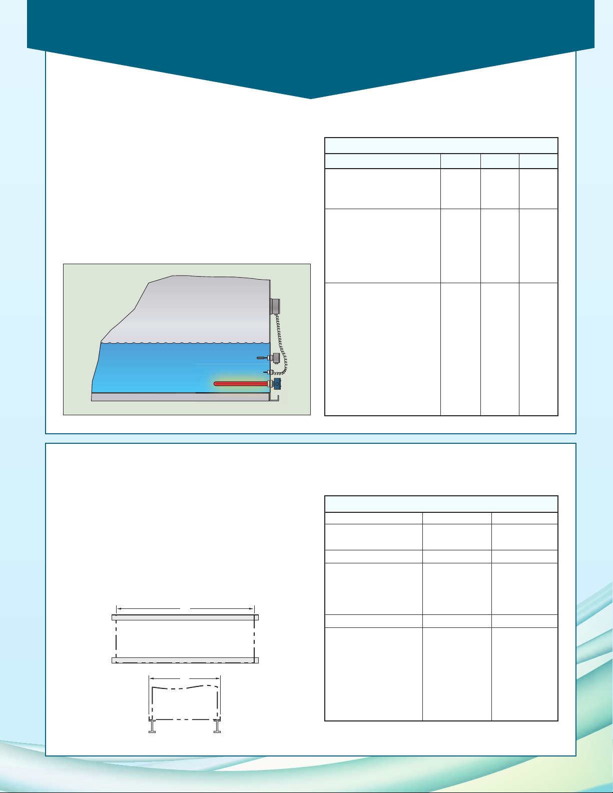
Electric Heaters
A
B
Electric Heaters/Steel Support
Electric immersion heaters are available factory installed in the
basin of the condenser. They are sized to maintain a +40° F
pan water temperature with the fans off and an ambient air
temperature of 0°F, -20°F, or -40°F. They are furnished with a
combination thermostat/low water protection device to cycle
the heater on when required and to prevent the heater
elements from energizing unless they are completely
submerged. All components are in weather proof enclosures
for outdoor use. The heater power contactors and electric
wiring are not included as standard.
PMC-E Heater Sizes
Models 0°F -20°F -40°F
PMC-175E to PMC-240E 579
PMC-250E to PMC-375E (2) 4 (2) 5 (2) 7
PMC-332E to PMC-530E 8 12 16
PMC-503E to PMC-792E (2) 6 (2) 9 (2) 12
PMC-725E to PMC-1056E (2) 8 (2) 12 (2) 15
PMC-1006E to PMC-1586E (2) 12 (4) 9 (4) 12
PMC-376E to PMC-640E 10 15 20
PMC-568E to PMC-955E (2) 7 (2) 12 (2) 15
PMC-715E to PMC-1013E (2) 8 (2) 12 (2) 15
PMC-911E to PMC-1258E (2) 9 (2) 15 (2) 18
PMC-752E to PMC-1286E (2) 9 (2) 15 (2) 18
PMC-1137E to PMC-1911E (2) 15 (4) 10 (4) 15
PMC-1705E to PMC-2019E (2) 15 (4) 12 (4) 15
Steel Support
The recommended support for EVAPCO condensers is
structural “I” beams located under the outer flanges and
running the entire length of the unit. Mounting holes, 3/4” in
diameter are located in the bottom channels of the pan
section to provide for bolting to the structural steel. (Refer to
certified drawings from the factory for bolt hole locations.)
Beams should be level to within 1/8” in 6’ before setting the
unit in place. Do not level the unit by shimming between it
and the “I ” beams as this will not provide proper longitudinal
support.
PMC-E Dimensions
5' Wide Models AB
PMC-175E to 240E 11’ 11-5/8” 6’ 4”
250E to 375E 18’ 1/8” 6’ 4”
10' Wide Models AB
PMC-332E to 530E 11’ 11-3/4” 9’ 9-3/4”
503E to 792E 18’ 1/8” 9’ 9-3/4”
725E to 1056E 24’ 7/8” 9’ 9-3/4”
1006E to 1586E 36’ 2” 9’ 9-3/4”
12' Wide Models AB
PMC-376E to 640E 11’ 11-3/4” 11’ 10-3/8”
568E to 955E 18’ 1/8” 11’ 10-3/8”
715E to 1013E 20’ 1/4” 11’ 10-3/8”
911E to 1258E 24’ 7/8” 11’ 10-3/8”
752E to 1286E 24’ 7/8” 11’ 10-3/8”
1137E to 1911E 36’ 2” 11’ 10-3/8”
1705E to 2019E 40’ 2” 11’ 10-3/8”
21
Page 22

Application
Design
EVAPCO units are heavy-duty construction and designed for
long trouble-free operation. Proper equipment selection,
installation and maintenance is, however, necessary to ensure
ood unit performance. Some of the major considerations in
g
the application of a condenser are presented below. For
additional information, contact the factory.
Air Circulation
In reviewing the system design and unit location, it is
important that proper air circulation be provided. The best
location is on an unobstructed roof top or on ground level
away from walls and other barriers. Care must be taken when
locating condensers in wells or enclosures or next to high
walls. The potential for recirculation of hot, moist discharge
air back into the fan intake exists. Recirculation raises the wet
bulb temperature of the entering air causing the condensing
pressure to rise above the design. For these cases, a
discharge hood or ductwork should be provided to raise the
overall unit height even with the adjacent wall, thereby
reducing the chance of recirculation. Good engineering
practice dictates that the evaporative condenser’s discharge
air not be directed or located close to or in the vicinity of
building air intakes. Engineering assistance is available from
the factory to identify potential recirculation problems and
recommend solutions.
For additional information regarding layout of evaporative
condensers, see EVAPCO Bulletin entitled “Equipment
Layout”.
Piping
Condenser piping should be designed and installed in
accordance with generally accepted engineering practice. All
piping should be anchored by properly designed hangers and
supports with allowance made for possible expansion and
contraction. No external loads should be placed upon
condenser connections, nor should any of the pipe supports be
anchored to the unit framework. For additional information
concerning refrigerant pipe sizing and layout, see EVAPCO
Bulletin entitled “Piping Evaporative Condensers”.
Super Low Sound Fan
Evapco’s Super Low Sound Fan on the PMC-E Condenser
utilizes an extremely wide chord blade design available for
sound sensitive applications where the lowest sound levels are
desired. The fan is one pieces molded heavy duty FRP
construction utilizing a forward swept blade design. The
Super Low Sound Fan reduces sound levels 10 to 13 dB(A)
compared to the standard PMC-E Fan. For a detailed analysis,
please contact your EVAPCO Sales Representative.
Maintaining the Recirculated Water System
The heat rejection in a condenser is accomplished by the
evaporation of a portion of the recirculated spray water. As
this water evaporates, it leaves behind all of its mineral content
and impurities. Therefore, it is important to bleed-off an
mount of water equal to that which is evaporated to prevent
a
the build-up of these impurities. If this is not done, the mineral
or the acidic nature of the water will continue to increase. This
will ultimately result in heavy scaling or a corrosive condition.
Bleed-off
Each unit supplied with a pump mounted on the side is
furnished with a clear bleed line for visual inspection and a
valve which, when fully open, will bleed-off the proper amount
of water. If the make-up water supplying the unit is relatively
free of impurities, it may be possible to cut back the bleed, but
the unit must be checked frequently to make sure scale is not
forming. Make-up water pressure should be maintained
between 20 and 50 psig.
Water Treatment
In some cases the make-up will be so high in mineral content
that a normal bleed-off will not prevent scaling. In this case
water treatment will be required and a reputable water
treatment company familiar with the local water conditions
should be consulted.
Any chemical water treatment used must be compatible with
the construction of the unit. If acid is used for treatment, it
should be accurately metered and the concentration properly
controlled. The pH of the water should be maintained
between 6.5 and 8.0. Units constructed of galvanized
steel operating with circulating water having a pH of 8.3
or higher will require periodic passivation of the
galvanized steel to prevent the formation of “white rust”.
Batch chemical feeding is not recommended because it does
not afford the proper degree of control. If acid cleaning is
required extreme caution must be exercised and only
inhibited acids recommended for use with galvanized
construction should be used. For more information see
EVAPCO Bulletin entitled “Maintenance Instructions”.
Control of Biological Contamination
Water quality should be checked regularly for biological
contamination, If biological contamination is detected, a more
aggressive water treatment and mechanical cleaning program
should be undertaken. The water treatment program should
be performed in conjunction with a qualified water treatment
company. It is important that all internal surfaces be kept clean
of accumulated dirt and sludge. In addition, the drift
eliminators should be maintained in good operating condition.
22
Page 23

Mechanical Specifications
Furnish and install, as shown on the plans, an EVAPCO
odel _____________ evaporative condenser. Each unit
m
shall have condensing capacity of _____________ BTUH
eat rejection, operating with _____________refrigerant at
h
_____°F condensing temperature and ______ °F design
_
wet bulb temperature.
IBC Compliance
The condenser shall be designed and constructed to meet
the International Building Code specifications for installed
components per ASCE 7-05. The manufacturer shall
provide a certificate of compliance to demonstrate that the
equipment/unit has been independently tested and certified
in accordance with the IBC program.
Pan and Casing
The pan and casing shall be constructed of G-235 hot-dip
galvanized steel for long life and durability. The heat transfer
section shall be removable from the pan to provide easy
handling and rigging.
The pan/fan section shall include fans, motors and drives
mounted and aligned at the factory. These items shall be
located in the dry entering air stream to provide maximum
service life and easy maintenaince. The pan bottom shall be
sloped to the drain to ensure easy draining and to facilitate
cleaning. Standard pan accessories shall include circular
access doors, stainless steel strainers, wastewater bleed line
with adjustable valve and brass makeup valve, with an
unsinkable foam filled plastic float.
Power-Mizer Fan Drives
Fans shall be vane-axial type constructed of cast aluminum
alloy blades. They shall be arranged in a two-stage system
installed in a closely fitted cowl with venturi air inlet and air
stabilizing vanes. Fan shaft bearings shall be a heavy-duty self
aligning ball type with grease fittings extended to the outside
of the unit.
The fan drive shall be solid backed Power-Band constructed
of neoprene with polyester cords designed for 150% of motor
nameplate horsepower. Drives are to be mounted and
aligned at the factory.
Each fan shall be driven individually by a dedicated fan motor.
Fan motors may be cycled independently without harmful
moist air bypass.
Heat Transfer Coil
The coil(s) shall be all prime surface steel, encased in steel
framework with the entire assembly hot-dip galvanized after
fabrication. Coil(s) shall be designed with sloping tubes for
free drainage of liquid refrigerant and tested to 400 psig air
pressure under water.
Water Distribution System
The system shall provide a water flow rate of 6 GPM over
each square foot of the unit face area to ensure proper
flooding of the coil. The spray header shall be constructed
of schedule 40, PVC pipe for corrosion resistance. All spray
branches shall be removable and include a threaded end
plug for cleaning. The water shall be distributed over the
entire coil surface by heavy-duty ABS spray nozzles with
large 1-1/4” diameter opening and internal sludge ring to
eliminate clogging. Nozzles shall be threaded into a spray
header to provide easy removal for maintenance.
Water Recirculation Pump
The pump(s) shall be a close-coupled, centrifugal type with
mechanical seal, installed at the factory. _____________
horsepower totally enclosed, motor shall be furnished suitable
for outdoor service on _____________ volts, _____________
hertz, and _____________ phase.
Eliminators
The eliminators shall be constructed entirely of inert
polyvinyl chloride (PVC) in easily handled sections. The
eliminator design shall incorporate three changes in air
direction to assure complete removal of all entrained
moisture from the discharge air stream. Maximum drift rate
shall be less than 0.001% of the circulating water rate.
Finish
All pan and casing materials shall be constructed of G-235
heavy gauge mill hot-dip galvanized steel for maximum
protection against corrosion. During fabrication, all panel
edges shall be coated with 95% pure zinc-rich compound.
Fan Motor
_________ horsepower totally enclosed fan cooled
motor(s) with 1.15 service factor shall be furnished suitable for
outdoor service on _________ volts, _________ hertz,
and _________ phase. Motor(s) shall be mounted on an
adjustable base.
23
Page 24

W
orld Headquarters/
Research and
Development Center
E
VAPCO Facilities
W
Re
D
OUR PRODUCTS ARE MANUFACTURED WORLDWIDE
EVAPCO, Inc. — World Headquarters & Research/ Development Center
North America
EVAPCO, Inc.
World Headquarters
P.O. Box 1300
Westminster, MD 21158 USA
410-756-2600 p | 410-756-6450 f
[email protected]
EVAPCO East
5151 Allendale Lane
Taneytown, MD 21787 USA
410-756-2600 p | 410-756-6450 f
[email protected]
EVAPCO East
Key Building
Taneytown, MD USA
410-756-2600 p
[email protected]
EVAPCO Midwest
Greenup, IL USA
217-923-3431 p
[email protected]
EVAPCO West
Madera, CA USA
559-673-2207 p
[email protected]
EVAPCO Iowa
Lake View, IA USA
712-657-3223 p
EVAPCO Iowa
Sales & Engineering
Medford, MN USA
507-446-8005 p
[email protected]
EVAPCO Newton
Newton, IL USA
618-783-3433 p
[email protected]
EVAPCOLD
Greenup, IL USA
217-923-3431 p
[email protected]
Bulletin 106D
2M/08-18/DGD
P.O. Box 1300 • Westminster, MD 21158 USA
410-756-2600 p
EVAPCO-BLCT Dry Cooling, Inc.
1011 US Highway 22 West
Bridgewater, NJ 08807 USA
Phone: 1-908-379-2665
E-mail: [email protected]
EVAPCO-BLCT Dry Cooling, Inc.
7991 Shaffer Parkway
Littleton, CO 80127 USA
Phone: 1-908-379-2665
E-mail: [email protected]
Spare Parts Phone: 908-895-3236
Spare Parts e-mail: [email protected]
EVAPCO Power México S. de R.L. de C.V.
Calle Iglesia No. 2, Torre E
Tizapan San Ángel, Del. Álvaro Obregón
Ciudad de México, D.F. México 01090
Phone: +52 (55) 8421-9260
e-mail: [email protected]
Refrigeration Valves & Systems Corporation
A wholly owned subsidiary of EVAPCO, Inc.
Bryan, TX USA
979-778-0095 p
[email protected]
EvapTech, Inc.
A wholly owned subsidiary of EVAPCO, Inc.
Lenexa, KS USA
913-322-5165 p
[email protected]
Tower Components, Inc.
A wholly owned subsidiary of EVAPCO, Inc.
Ramseur, NC USA
336-824-2102 p
[email protected]
EVAPCO Alcoil, Inc.
A wholly owned subsidiary of EVAPCO, Inc.
York, PA USA
717-347-7500 p
[email protected]
• [email protected] • evapco.com
www.evapco.com
Europe
EVAPCO Europe BVBA
European Headquarters
Heersterveldweg 19
Industrieterrein Oost
3700 Tongeren, Belgium
(32) 12-395029 p | (32) 12-238527 f
[email protected]
EVAPCO Europe, S.r.l.
Milan, Italy
(39) 02-939-9041 p
[email protected]
EVAPCO Europe, S.r.l.
Sondrio, Italy
EVAPCO Europe GmbH
Meerbusch, Germany
(49) 2159 6956 18 p
[email protected]
EVAPCO Air Solutions
A wholly owned subsidiary of EVAPCO, Inc.
Aabybro, Denmark
(45) 9824 4999 p
[email protected]
EVAPCO Air Solutions GmbH
Garbsen, Germany
(49) 5137 93875-0 p
[email protected]
Evap Egypt Engineering Industries Co.
A licensed manufacturer of EVAPCO, Inc.
Nasr City, Cairo, Egypt
2 02 24022866/2 02 24044997 p
[email protected] / [email protected]
EVAPCO S.A. (Pty.) Ltd.
A licensed manufacturer of EVAPCO, Inc.
Isando 1600, Republic of South Africa
(27) 11-392-6630 p
[email protected]
Asia/Pacific
EVAPCO Asia/Pacific Headquarters
1159 Luoning Road
Baoshan Industrial Zone
Shanghai 200949, P.R. China
(86) 21-6687-7786 p | (86) 21-6687-7008 f
[email protected]
EVAPCO (Shanghai) Refrigeration Equipment Co., Ltd.
Baoshan Industrial Zone Shanghai, P.R. China
(86) 21-6687-7786 p
[email protected]
Beijing EVAPCO Refrigeration Equipment Co., Ltd.
Huairou District Beijing, P.R. China
010-6166-7238 p
[email protected]
EVAPCO Air Cooling Systems (Jiaxing) Company, Ltd.
1288 Kanghe Road,
Xiuzhou district, Jiaxing, Zhejiang, China
[email protected]
EVAPCO Australia (Pty.) Ltd.
Riverstone NSW 2765, Australia
(61) 2 9627-3322 p
[email protected]
EVAPCO Composites Sdn. Bhd
Rawang, Selangor, Malaysia
(60-3) 6092-2209 p
EvapTech Asia Pacific Sdn. Bhd
A wholly owned subsidiary of EvapTech, Inc.
Puchong, Selangor, Malaysia
(60-3) 8070-7255 p
[email protected]
South America
EVAPCO Brasil
Equipamentos Industriais Ltda.
Al. Vênus, 151 – CEP: 13347-659
Indaiatuba –São Paulo – Brasil
(55+11) 5681-2000 p
Fan Technology Resource
Cruz das Almas – Indaiatuba
São Paulo, Brasil 13308-200
55 (11) 4025-1670
[email protected]
©2018 EVAPCO, Inc.
Committed to making life easier, more reliable and more sustainable for people everywhere
Committed to making life easier, more reliable and more sustainable for people everywhere
 Loading...