

EVAPCO ATC-E, eco-ATC, LSWA-H, LSCE, LRW Operation And Maintenance Instruction Manual
...
Bulletin 116-E Metric
EVAPCO Products are Manufactured Worldwide
EVAPCO, Inc. (World Headquarters) P.O. Box 1300, Westminster, Maryland 21158 USA
Phone (410) 756-2600 - Fax (410) 756-6450
For EVAPCO Authorized Parts and Service,
Contact Your Local Mr. GoodTower
®
Service Provider
or the EVAPCO Plant Nearest You
www.evapco.eu
ATC-E / eco-ATC eco-ATWE LSWA(-H) / LSCE LRW(-H) / LRC ESWA PMCQ
ATW / eco-ATW
EUROPEAN
OPERATION AND MAINTENANCE INSTRUCTIONS
For EVAPCO Induced Draft and Forced Draft
Closed Circuit Coolers and Evaporative Condensers
EVAPCO Europe
bvba
Heersterveldweg 19
Industrieterrein Oost
3700 Tongeren, Belgium
Phone: (32) 12 395029
Fax: (32) 12 238527
E-mail: evapco.europe@ evapco.be
EVAPCO Europe S.r.l.
Via Ciro Menotti 10
I-20017 Passirana di Rho
Milan, Italy
Phone: (39) 02 9399041
Fax: (39) 02 93500840
Email: evapcoeurope@evapco.it
EVAPCO Europe GmbH
Insterburger Straße, 18
D-40670 Meerbusch, Germany
Phone: (49) 2159-6956-0
Fax: (49) 2159-6956-11
Email: info@evapco.de

2
Operation and Maintenance Instructions
Table of Contents
Introduction..................................................................................4
Safety Precautions / Remaining Risks ............................................................4
Installation Precautions ....................................................................5
Storage Precautions ......................................................................5
Label on the coil section(s) .................................................................5
Terminology..................................................................................6
Initial Storage and/or Idle Period Recommendations................................................6
International Building Code Provision ............................................................7
Initial and Seasonal Start-Up Checklist ...........................................................7
General ................................................................................7
Initial and Seasonal Start-Up................................................................7
Maintenance Checklist ....................................................................9
Seasonal Shut-Down Checklist.............................................................11
Basic Closed Circuit Cooler Sequence of Operation ...............................................11
Fan System .................................................................................12
Fan Motor Bearings ......................................................................12
Fan Shaft Ball Bearings ...................................................................12
Fan Shaft Sleeve Bearings – (1,2 m wide LS units only) ..........................................13
Fan Belt Adjustment .....................................................................13
Air Inlet................................................................................14
Fan System – Capacity Control.................................................................15
Fan Motor Cycling .......................................................................15
Sequence of Operation for Fan Motor Cycling .................................................15
Two-Speed Motors ......................................................................15
Sequence of Operation for Two Fan Units with Two Speed Motors during Peak Load .............15
Variable Frequency Drives.................................................................15
Sequence of Operations / Guidelines for Multi-fan Units with a VFD during Peak Load ............16
Identify and Lock-out Harmful Resonant Frequencies..............................................16
Recirculated Water System – Routine Maintenance................................................17
Suction Strainer in Cold Water Basin ........................................................17
Cold Water Basin........................................................................17
Operating Level of Water in Cold Water Basin .................................................18
Water Make Up Valve ....................................................................18
Drift Eliminators .........................................................................19
Pressurized Water Distribution Systems ......................................................19
Bleed-Off Valve .........................................................................20
Pump (When Supplied) ...................................................................20
Coils ......................................................................................20
Evaporative Coil(s).......................................................................20
Dry Coils ..............................................................................20
Water Treatment and Water Chemistry ..........................................................20
Bleed or Blowdown ......................................................................20
Galvanized Steel – Passivation .............................................................20
Water Chemistry Parameters...............................................................21
Control of Biological Contamination .........................................................21
Gray Water and Reclaimed Water ...........................................................22
Air Contamination .......................................................................22
Cold Weather Operation ......................................................................22
Unit Layout ............................................................................22
Freeze Protection of Recirculating Water .....................................................22
Freeze Protection of Closed Circuit Cooler Coils ...............................................24

3
Operation and Maintenance Instructions
Unit Accessories ........................................................................25
Cold Water Basin Heaters ...........................................................25
Remote Sumps ....................................................................25
Electric Water Level Control ..........................................................25
Vibration Cut Out Switches...........................................................25
Capacity Control Methods for Cold Weather Operation ..........................................25
Induced Draft Unit Capacity Control ...................................................25
Forced Draft Unit Capacity Control ....................................................26
Ice Management ........................................................................26
Induced Draft Units.................................................................26
Forced Draft Units..................................................................27
Troubleshooting .............................................................................27
Replacement Parts...........................................................................28
Part Identification Drawings ...............................................................31
ATW & eco-ATW 0,9 m Wide Units ....................................................31
ATC-E, ATW, eco-ATW 1,2 m Wide Units - 1 Fan .........................................32
ATC-E, ATW, eco-ATW 1,2 m Wide Units - 2 Fans ........................................33
ATC-E, ATW, eco-ATC, eco-ATW 2,4 m Wide Units .......................................34
ATC-E, ATW, eco-ATC, eco-ATW 3 & 3,6 m Wide Units ....................................35
eco-ATWE 2,4 m Wide .............................................................36
eco-ATWE 3 m Wide ...............................................................37
eco-ATWE 3,6 m Wide .............................................................38
ESWA 2,4 m Wide Units ............................................................39
ESWA 3,6 m Wide Units ............................................................40
LSCE & LSWA 1,2 m Wide Units ......................................................41
LSCE & LSWA 1,5 m Wide Units ......................................................42
LSCE & LSWA 2,4 m & 3,0 m Wide Units (Single Side Fans) ................................43
LRC/LRW 1 m Wide Units ...........................................................44
LRC/LRW 1,5 m Wide Units .........................................................45
LRC/LRW 2,4 m Wide Units .........................................................46
4
Operation and Maintenance Instructions
Introduction
Congratulations on the purchase of your EVAPCO evaporative cooling unit. EVAPCO equipment is constructed of the highest
quality materials and designed to provide years of reliable service when properly maintained.
Evaporative cooling equipment is often remotely located and periodic maintenance checks are often overlooked. It is important
to establish a regular maintenance program and be sure that the program is followed. This bulletin should be used as a guide to
establish a program. A clean and properly serviced unit will provide a long service life and operate at peak efficiency.
This bulletin includes recommended maintenance services for unit start up, unit operation and unit shutdown and the frequency of
each. Please note: the recommendations of frequency of service are minimums. Services should be performed more often when
operating conditions necessitate.
Become familiar with your evaporative cooling equipment. Refer to the isometric drawings located on pages 29-45 for information
on the arrangement of components in your equipment.
If you should require any additional information about the operation or maintenance of this equipment, contact your local EVAPCO
representative. You may also visit www.evapco.eu for more information.
Safety Precautions / Remaining Risks
Qualified personnel should use proper care, procedures and tools when operating, maintaining or repairing this equipment in order
to prevent personal injury and/or property damage. The warnings listed below are to be used as guidelines only.
WARNING: Evaporative cooling equipment is considered as “Partly completed machinery”. “Partly completed machinery” is
a totality which almost forms a machinery but in itself cannot fulfil any particular function. The considered cooling
equipment is missing the components to safely connect it to the source of energy and motion in a controlled way.
The considered cooling equipment is custom made but is not designed to address the specific needs and safety
measures for a specific application. Each application requires a unique designed and integrated operational,
control and safety strategy that links all components of the installation and eventually a back-up system in a safe
and controlled way.
WARNING: This equipment should never be operated without fan screens and access doors properly secured, locked and in
place.
WARNING: For assembling or disassembling the unit or unit sections, please follow the rigging instructions or the
instructions on the yellow labels on the individual unit sections.
WARNING: During maintenance operations, the worker must use adequate personal protection equipment (PPE - A
minimum, but not limited list of PPE are safety shoes, glasses, gloves, respiration protection, helmet) as
prescribed by local authorities.
WARNING: For any exceptional, non routine work to be carried out, protection and adequate safety measures should be
considered and a Last Minute Risks Assessment (LMRA) must be made by an authorized person in accordance
with safety requirements of the country.
WARNING: A lock-out / tag-out procedure, integrated with the Process Control System, must be foreseen by the
customer. Before performing any type of service or inspection of the unit, make certain that all power has
been disconnected and locked in the “OFF” position.
WARNING: The top horizontal surface of any unit is not intended to be used as a working platform. No routine service
work is required from this area. For any exceptional, non routine work to be carried out on top of the
unit, use ladders, PPE and adequate safety measures against the risk of a fall, in accordance with safety
requirements of the country in question.
WARNING: The recirculating water system may contain chemicals or biological contaminants including Legionella
Pneumophila, which could be harmful if inhaled or ingested. Direct exposure to the discharge airstream
and the associated drift generated during operation of the water distribution system and/or fans, or mists
generated while cleaning components of the water system, require respiratory protection equipment
approved for such use by governmental occupational safety and health authorities.
WARNING: To avoid water and air contamination as a result of biological fouling, the cooling equipment must be
maintained in accordance, but not limited to the operating and maintenance instructions. All local
legislation related to evaporative cooling equipment must be respected.
WARNING: Accessories like platform and ladders are optional. In case these options are not taken in consideration, the
customer must design the installation to comply with local safety and access requirements and legislation.
5
Operation and Maintenance Instructions
WARNING: Sound reducing options are available. In case these options are not taken in consideration, the customer
must design the installation to comply with local sound requirements and legislation.
WARNING: In order to avoid excessive pressure, proper safety valves should be foreseen in the cooling installation.
These safety measures are not delivered by Evapco and are the responsibility of the customer/contractor.
The application of these safety measures has to be evaluated for the cooling system as a whole and not
limited to the partly completed machinery.
WARNING: Atmospheric corrosion and corrosion due to the use of corrosive media at the inside/or outside of the
coils is forbidden and voids the PED certification.
WARNING: Every handling that effects the integrity of the pressure vessel (example, but not limited to, welding,
grinding, drilling, ... ) is forbidden and voids the PED certification.
Installation Precautions
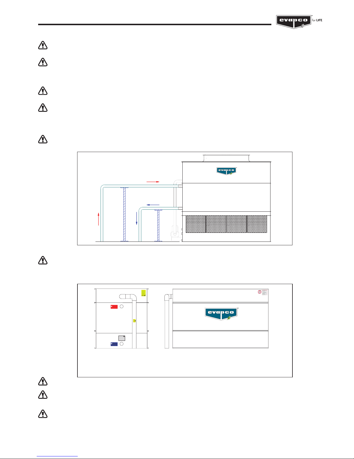
WARNING: The coil connections are not designed to support piping. The water / glycol / refrigerant piping always
need to be supported (by others). See also Bulletin 131-E “Piping Evaporative Condensers”.
Storage Precautions
WARNING: Never use plastic sheets or tarps to protect a unit during storage. This practice can trap heat inside the
unit and could potentially cause damage to plastic components.
Label on the coil section(s)
WARNING: Do not operate the pressure vessel at service conditions outside of the PED nameplate located
at the coil connection. See position 1 for the location of the PED nameplate.
WARNING: Maximum working temperature of the pressure vessel as mentioned on the PED nameplate exceeds
the nominal operating temperature of the unit. Never apply pressure vessel temperatures above 65°C
or consult the factory for approval.
WARNING: Legal periodic controls of the pressure vessel need to be performed according to the legal requirements
of the country.
TEST bar DATE
PRESSURE
TEMPERATURE -10°C / +120°C
WORKING
DESIGN TEMPERATURE -20°C / +140°C
FLUID
VOLUME
INDUSTRIETERREIN OOST 4010
EUROPE N.V.EVAPCO
DWG.
S.N.
MODEL
YEAR
0036
BELGIUM
B-3700 TONGEREN
MAX WORKING PRESSURE bar
FLUID OUT
SORTIE DU FLUIDE
FLUESSIGKEIT AUS
USCITA FLUIDO
12A
FLUID IN
ENTREE DU FLUIDE
FLUESSIGKEIT EIN
ENTRATA FLUIDO
11A
2A
(2)
2 (2)
35
17A
1
12A
11A
34
1.
PED NAMEPLATE/SERVICE CONDITIONS
2. EVAPCO LOGO (both sides)
2A. RIGGING INSTRUCTIONS (both ends)
11A. FLUID IN
12A. FLUID OUT
17A. WARNING ELIMINATORS
34. WARNING PVC PIPE
35. DO NOT COVER ELIMINATORS
6
Operation and Maintenance Instructions
Terminology
Throughout this manual, the terms “Induced Draft” and “Forced Draft” are used. Below is a list of EVAPCO Closed Circuit Cooler
and Condenser products offerings and associated terminology.
Induced Draft equipment includes the following Evapco Product Models:
< ES Product Lines
• ESW - Closed Circuit Cooler
• ESWA - Closed Circuit Cooler
< AT Product Lines
• ATW - Closed Circuit Cooler
• ATC-E - Evaporative Condenser
< Containerized Product Lines
• CATW – Closed Circuit Cooler
• CATC - Evaporative Condenser
< eco Product Lines
• eco-ATW – Closed Circuit Cooler
• eco-ATWE – Closed Circuit Cooler
• eco-ATC - Evaporative Condenser
Forced Draft equipment includes the following Evapco Product Models:
< LR Product Lines
• LRW - Closed Circuit Cooler
• LRC - Evaporative Condenser
< LS Product Lines
• LSWA - Closed Circuit Cooler
• LSCE - Evaporative Condenser
< PM Product lines
• PMCQ - Evaporative Condenser
Initial Storage and/or Idle Period Recommendations
If the unit will sit for idle periods of time it is recommended that the following be performed in addition to all component
manufacturers recommended maintenance instructions.
• The fan, pump and motor bearings need to be turned by hand at least once a month. This can be accomplished by tagging
and locking out the unit’s disconnect, grasping the fan assembly (or removing pump motor fan guard), and rotating it several
turns.
• If unit sits longer than one month insulation test motor windings semi-annually.
• If fan motor sits idle for at least 24 hours while the spray pumps are energized distributing water over the coil, motor space
heaters are suggested and (if equipped) should be energized. Alternatively, fan motors may be energized for 10 minutes,
twice daily, to drive any moisture condensation out of the motor windings.
7
Operation and Maintenance Instructions
International Building Code Provisions
The International Building Code (IBC) is a comprehensive set of regulations addressing the structural design and installation
requirements for building systems – including HVAC and industrial refrigeration equipment. The code provisions require that
evaporative cooling equipment and all other components permanently installed on a structure must meet the same seismic design
criteria as the building.
All items attached to the Evapco Closed Circuit Coolers or Evaporative Condensers must be independently reviewed and isolated
to meet applicable wind and seismic loads. This includes piping, ductwork, conduit, and electrical connections. These items
must be flexibly attached to the Evapco unit so as not to transmit additional loads to the equipment as a result of seismic or wind
forces.
Initial and Seasonal Start-Up Checklist
General
1. VerifythattheoverallinstallationreflectstherequirementsoftheinstallationguidelinesfoundinEVAPCOBulletin311–
Equipment Layout Manual, available at www.evapco.eu.
2. For multi-speed fan motors, verify that 30 second or greater time delays are provided for speed changes when switching from
high to low speed. Also check to see if interlocks are provided to prevent simultaneously energizing high and low speed, and
confirm both speeds operate in the same direction.
3. Verify all safety interlocks work properly.
4. For units operating with a variable frequency drive, make certain that minimum speed requirements have been set. Check with
VFD manufacturer for recommended minimum speeds and for recommendations on locking out resonance frequencies.
See “Fan System Capacity Control” section for more information.
5. Verify that a water treatment plan has been implemented including passivation of galvanized steel units.
See “Water Treatment” section for more details.
6. If the unit is going to sit idle for an extended period of time, follow all manufacturers’ fan motor and pump instructions for long
term storage. Plastic sheets or tarps should never be used to protect a unit during storage. This practice can trap heat inside
the unit, and could potentially cause damage to plastic components.
See your local EVAPCO representative for additional information on unit storage.
7. For units subject to freezing climates, high humidity climates, or idle periods lasting 24 hours or more, motor space heaters
are suggested and (if equipped) should be energized. Alternatively, fan motors may be energized for 10 minutes, twice daily, to
drive any moisture condensation out of the motor windings.
BEFORE BEGINNING ANY MAINTENANCE, BE CERTAIN THAT THE POWER IS TURNED OFF
AND THE UNIT IS PROPERLY LOCKED AND TAGGED OUT!
Initial and Seasonal Start-Up
1. Clean and remove any debris, such as leaves and dirt from the air inlets.
2. Flush the cold water basin (with the strainer screens in place) to remove any sediment or dirt.
3. Remove the strainer screen, clean and reinstall.
4. Check mechanical float valve to see if it operates freely.
5. Inspect water distribution system nozzles and clean as required. Check for proper orientation.
(This is not required at initial start-up. The nozzles are clean and set at the factory).
6. Check to ensure drift eliminators are securely in place and in the proper orientation.
7. Adjust fan belt tension as required. See “Fan Belt Adjustment” section.
8. Lubricate fan shaft bearings prior to seasonal start-up.
9. Turn the fan(s) and pump(s) by hand to insure it turns freely without obstructions.
10. Visually inspect the fan blades. Blade clearance should be approximately 10 mm* (6 mm minimum) from tip of blade to the fan
cowl. The fan blades should be securely tightened to the fan hub.
* Depending on fan type, this value can change.

8
Operation and Maintenance Instructions
11. If any stagnant water remains in the system including “dead legs” in the piping, the unit must be disinfected prior to the fans
being energized. Please refer to ASHRAE Guideline 12-2000 and CTI Guideline WTP-148 for more information and consult
local legislation prior to start-up.
12. Fill the cold water basin manually up to the overflow connection.
13. For closed circuit coolers only, fill the heat exchanger coil with the specified fluid and vent air from the system before
pressurizing, using vents on coil inlets.
14. All new evaporative cooling equipment and associated piping should be pre-cleaned and flushed to remove grease, oil, dirt,
debris and other suspended solids prior to operation. Any pre-cleaning chemistry should be compatible with the cooling
equipment’s materials of construction. Alkaline formulations should be avoided for systems which include galvanized materials
of construction.
15. Closed hydronic systems connected to either a closed-circuit cooler or dry cooler should be pre-cleaned and flushed to
remove debris, grease, flash rust, oil, and other suspended solids prior to operation. Evapco recommends the use of inhibitor
chemistry or inhibited glycol to minimize corrosion and scale during normal operation.
For eco-WE & eco-W with optional controls, see controls O&M for proper start up procedure.
After the unit has been energized, check the following:
1. Adjust mechanical float valve as required to the proper water level.
2. Unit basin should be filled to the proper operating level. See “Recirculating Water System Operating Levels” section for more
details.
3. Verify fan is rotating in proper direction.
4. Start the spray water pump and check for proper rotation as indicated by the arrow on the front cover.
5. Measure voltage and current on all three power leads of pump and fan motor. The current should not exceed the motor
nameplate full load amp rating taking the service factor into account.
6. Adjust bleed valve to proper flow rate. Consult your qualified water treatment person to fine tune the minimum bleed
necessary.
7. See fan and pump motor manufacturer maintenance and long term storage instructions for more detailed information. The
motors should be lubricated and serviced in accordance with manufacturers instructions.
9
Operation and Maintenance Instructions
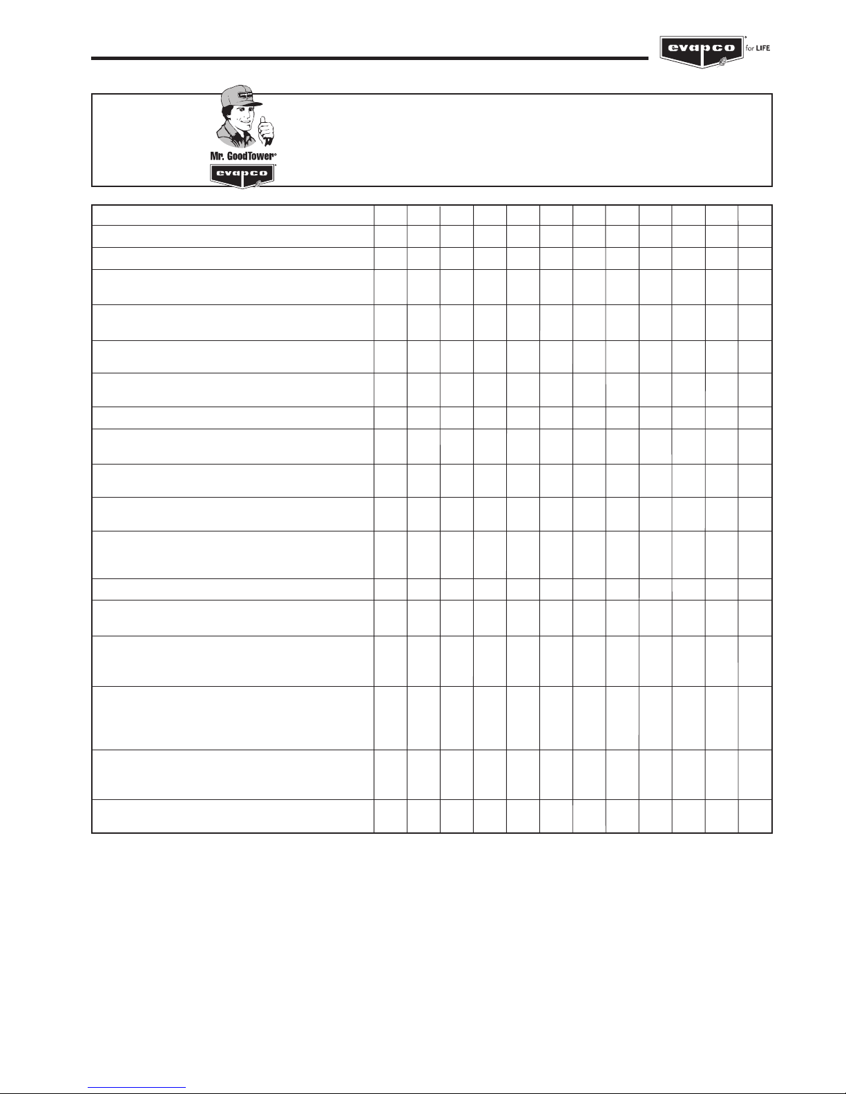
PROCEDURE
1. Clean pan strainer - monthly or as needed
2. Clean and flush pan* - quarterly or as needed
3. Check bleed-off valve to make sure it is
operative - monthly
4. Lubricate pump and pump motor according to
manufacturer’s instructions
5. Check operating level in pan and adjust float
valve if necessary - monthly
6. Check water distribution system and spray
pattern - monthly
7. Check drift eliminators - quarterly
8. Check the fan blades for cracks, missing
balancing weights, and vibrations - quarterly
9. Check sheaves and bushings for corrosion.
Scrape and coat with ZRC - annually
10. Lubricate fan shaft bearings - every 1000
hours of operation or every three months
11. Lubricate fan motor bearings - see mfg’s
instructions. Typically for non-sealed bearings,
every 2-3 years
12. Check belt tension and adjust - monthly
13. Inspect and grease sliding motor base -
annually or as needed
14. Check fan screens, inlet louvers, fans and
(dry) cooler coil. Remove any dirt or debris –
monthly
15. Inspect and clean protective finish - annually
- Galvanized: scrape and coat with ZRC
- Stainless: clean and polish with a
stainless steel cleaner.
16. Check water quality for biological contamination.
Clean unit as needed and contact a water
treatment company.
17. Check coil surface for scale and/or corrosion -
every 6 months
JAN FEB MAR APR MAY JUN JUL AUG SEP OCT NOV DEC
MAINTENANCE CHECKLIST
* Evaporative Cooling Equipment must be cleaned on a regular basis to prevent the growth of bacteria including Legionella Pneumophila.

10
Operation and Maintenance Instructions
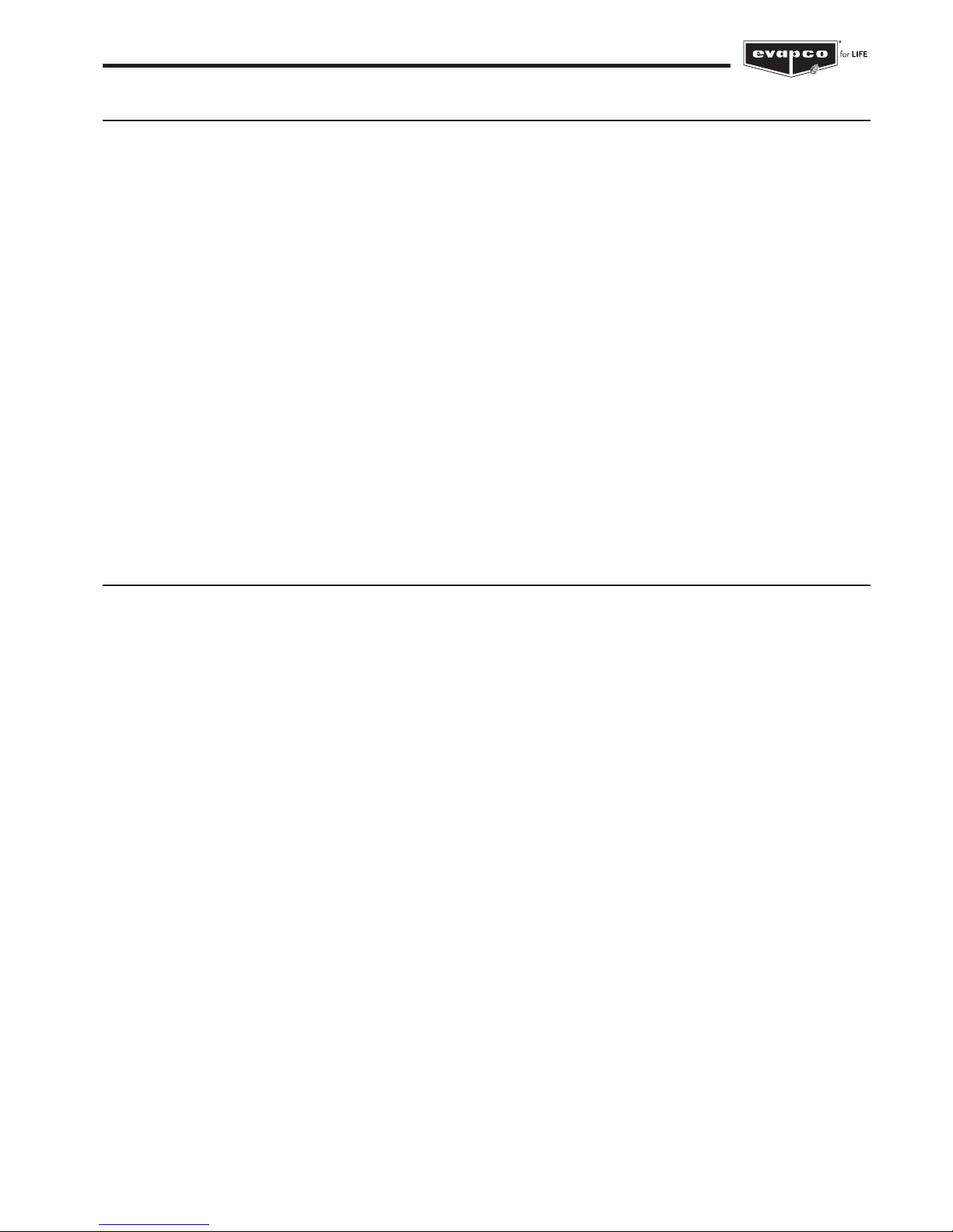
1. Two or more days: energize motor space
heaters or run motor for 10 min twice daily
2. One Month or longer: Rotate motor shaft/fan
10 turns – bi-weekly
3. One Month or longer: Megger test motor
windings – semi-annually
OPTIONAL ACCESSORIES:
1. Heater – Inspect junction box for loose wiring
and moisture – one month after start-up and
semi-annually
2. Heater – Inspect elements for scale build-up –
quarterly
3. Electronic Water Level Controller – Inspect
junction box for loose wiring and moisture –
semi-annually
4. Electronic Water Level Controller – Clean probe
ends of scale build-up – quarterly
5. Electronic Water Level Controller –Clean inside
the standpipe – annually
6. Solenoid Make-up Valve – Inspect and clean
valve of debris – as needed
7. Vibration Switch (mechanical) – Inspect
enclosure for loose wiring and moisture –
one month after start-up and monthly
8. Vibration Switch – Adjust the sensitivity -
during start-up and annually
9. Sump Sweeper Piping – Inspect and clean
piping of debris – semi-annually
JAN FEB MAR APR MAY JUN JUL AUG SEP OCT NOV DEC
DURING IDLE PERIODS:
MAINTENANCE CHECKLIST
(optional accessories)
11
Operation and Maintenance Instructions
Seasonal Shut-Down Checklist
When the system is to be shut down for an extended period of time, the following services should be performed.
1. The evaporative cooling unit cold water basin should be drained
2. The cold water basin should be flushed and cleaned with the suction strainer screens in place.
3. The suction strainer screens should be cleaned and re-installed.
4. The cold water basin drain should be left open.
5. The fan shaft bearings and motor base adjusting screws should be lubricated. This should also be performed if the unit is
going to sit idle prior to initial start-up.
6. The make-up water supply, overflow and drain lines, as well as the recirculating pump and pump piping up to the
overflow level must be heat traced and insulated to account for any residual water.
7. The finish of the unit should be inspected. Clean and refinish as required.
8. The fan bearings and motor bearings need to be turned at least once a month by hand. This can be accomplished by
making sure the unit’s disconnect is tagged and locked out, and grasping the fan assembly, rotating it several turns.
9. Closed Circuit Coolers only - If the recommended minimum fluid flows thru the heat transfer coil cannot be maintained,
and there is no anti-freeze solution in the coil, the coil must be drained immediately whenever the system pumps are shut
down or flow stops during freezing conditions. This is accomplished by having automatic drain valves and air vents in the
piping to and from the cooler. Care must be taken to ensure that the piping is adequately insulated and sized to allow the
water to flow quickly from the coil. This method of protection should be used only in emergency situations and is neither
a practical nor recommended method of freeze protection. Coils should not be drained for an extended period of time, as
internal corrosion may occur. See Cold Weather Operation section of this document for more details.
See fan and pump manufacturer maintenance and long term storage instructions for more detailed instructions.
Basic Closed Circuit Cooler/Condenser Sequence of Operation
Note: The eco-ATW / eco-ATWE sequence of operation is unique and is explained in detail in the Sage2, Sage3 Panel
Control Manual.
System Off / No Load
The system pumps and fans are off. If the basin is full of water a minimum basin water temperature of 4°C must be maintained to
prevent freezing. This can be accomplished with the use of optional basin heaters. See the “Cold Weather Operation” section of
this bulletin for more details on cold weather operation and maintenance.
System / Condensing Temperature Rises
The recirculation pump turns on. The unit will provide approximately 10% cooling capacity with only the pump running. If the unit
has positive closure dampers they should be fully opened before the pumps turn on.
If the system temperature continues to rise, the unit fan is cycled on. For a variable speed controller, the fans are turned on to
minimum speed. See the “Fan System – Capacity Control” section of this bulletin for more details on fan speed control options. If
the system temperature continues to rise, then the fan speed is increased as required, up to full speed.
Note: During sub-freezing weather the minimum recommended speed for variable speed controllers is 50%. ALL FANS IN
OPERATING CELLS OF MULTIPLE CELL TOWERS MUST BE CONTROLLED TOGETHER TO PREVENT ICING IN THE FANS.
System Temperature Stabilizes
Control the leaving water temperature (closed circuit coolers) or condensing temperature (evaporative condensers) by modulating
the fan speeds with variable speed drives or by cycling fans on and off with single or two-speed drives.

12
Operation and Maintenance Instructions
System / Condensing Temperature Drops
Decrease the fan speed, as required.
System Off / No Load
The system pump turns off. The starter interlock will energize any optional basin heaters in cold weather.
The recirculation pump should not be used as a means of capacity control, and should not be cycled frequently.
Please see section “Capacity Control” for more informations.
Dry Operation
During colder winter months it is possible to turn off the spray pump, drain the cold water basin, and just cycle the fans. Be sure to
leave the basin drain open during this time to prevent collection of rain water, snow, etc. If the unit has positive closure dampers they
should be fully opened before the fans turn on. If this method will be used on a forced draft unit, be sure to verify that the motor and
drives have been properly sized to handle the reduction in static pressure experienced when the spray water is turned off.
NOTE: MINIMUM CONTROL POINT FOR PROCESS FLUID SHOULD NEVER BE LOWER THAN 6°C.
NOTE: WHEN A UNIT IS PROVIDED WITH A DISCHARGE DAMPER ASSEMBLY, THE CONTROL SEQUENCE SHOULD
CYCLE THE DAMPERS OPEN AND CLOSED ONCE A DAY REGARDLESS OF CAPACITY REQUIRMENTS TO PREVENT THE
ASSEMBLY FROM SEIZING. THE FAN MOTOR SHOULD BE SHUT OFF WHENEVER THE DAMPERS ARE CLOSED.
Fan System
The fan systems of both centrifugal and axial driven units are rugged; however, the fan system must be checked regularly and
lubricated at the proper intervals. The following maintenance schedule is recommended.
Fan Motor Bearings
EVAPCO evaporative cooling units use either a T.E.A.O. (Totally Enclosed Air Over) or a T.E.F.C. (Totally Enclosed Fan Cooled)
fan motor. These motors are built to “Cooling Tower Duty” specifications. The fan motor bearings for motors up to 30 kW are
lubricated for the lifecycle of the bearings, higher motor powers require relubrication (please see motor manual for more detail). All
fan motors are supplied with special moisture protection on the bearings, shaft and windings. After extended shut-down periods,
the motor should be checked with an insulation tester prior to restarting the motor.
Fan Shaft Ball Bearings
Lubricate the fan shaft bearings every 1,000 hours of operation or every three months for induced draft units. Lubricate the
fan shaft bearings every 2,000 hours of operation or every six months for forced draft units. Use any of the following synthetic
waterproof, inhibited greases which are suitable for operation between -40°C and 120°C. (For colder operating temperatures,
contact the factory).
- Chevron - Multifak Premiums 3 - Total - Ceran WR2
- Shell Alvanias - or similar
Feed grease slowly into the bearings or the seals may be damaged. A hand grease gun is recommended for this process.
When introducing new grease, all grease should be purged from the bearings.
13
Operation and Maintenance Instructions
Fan Shaft Sleeve Bearings – (1,2 m wide LS units only)
Lubricate the intermediate sleeve bearing(s) before unit start up. The reservoir should be checked several times during the first
week to ensure that the oil reserve is brought to full capacity. After the first week of operation, lubricate the bearing(s) every 1,000
hours of operation or every three months (whichever occurs first). High temperatures or poor environmental conditions may
necessitate more frequent lubrication. The oil reservoir consists of a large felt packed cavity within the bearing housing. It is not
necessary to maintain the oil level within the filler cup.
Use one of the following industrial grade, non-detergent mineral oils. Do not use a detergent based oil or oils designated heavy
duty or compounded. Different oils may be required when operating at temperatures below 0°C continuously.
Table 2 provides a short list of approved lubricants for each temperature range. Most automotive oils are detergent based and may
not be used. Detergent oils will remove the graphite in the bearing sleeve and cause bearing failure.
All bearings used on EVAPCO equipment are factory adjusted and self aligning. Do not disturb bearing alignment by tightening the
sleeve bearing caps.
Oil drippage may result from over-oiling or from using too light of an oil. Should this condition persist with correct oiling, it is
recommended that a heavier weight oil be used.
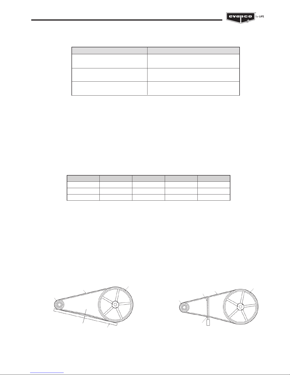
Fan Belt Adjustment
The fan belt tension should be checked at start up and again after the first 24 hours of operation to correct for any initial stretch.
To properly adjust the belt tension, position the fan motor so that the fan belt will deflect approximately 10 mm when moderate
pressure is applied midway between the sheaves. Figure 1 and Figure 2 show two ways to measure this deflection. Belt tension
should be checked on a monthly basis. A properly tensioned belt will not “chirp” or “squeal” when the fan motor is started.
Table 1 – Location of Grease Lube Line Fittings for Belt Driven Units
Please note: the removal of the fan screens is not necessary on forced draft units to access the extended lube line fittings.
Unit Description Location of Lube Line Fittings
Induced Draft Units: Located just beside the fan casing
0,9 m; 1,2 m; 2,4 m; 4,9 m wide access door
Induced Draft Units: Located inside the fan casing
3 m, 3,6 m, 6 m and 7,2 m wide access door
Forced Draft Units Located on the bearing support or
on the side of the unit
Table 2 – Sleeve Bearing Lubricants
Figure 2 – Method 2
BELT
DRIVER
SHEAVE
DRIVEN
SHEAVE
TAPE MEASURE
APPROXIMATELY 10 mm DEFLECTION
= PROPER BELT TENSION
Most EVAPCO units are supplied with extended grease lines to allow easy lubrication of the fan shaft bearings as shown
in Table 1.
BELT
DRIVER
SHEAVE
DRIVEN
SHEAVE
STRAIGHT EDGE
APPROXIMATELY 10 mm DEFLECTION
= PROPER BELT TENSION
Figure 1 – Method 1
Ambient Temp. Texaco
Mobil Exxon Total
-32°C to 0°C - DTE Heavy - -
-17°C to 43°C - - - -
0 to 38°C Regal R&O 220 DTE Oil BB Teresstic 220 -
14
Operation and Maintenance Instructions
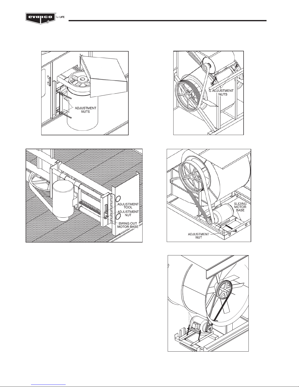
On induced draft belt driven units provided with externally mounted motors (2,3 m; 2,4 m and 4,8 m wide units), Figure 3, and
LS Style forced draft units, Figure 4, both J-type adjustment bolts on the adjustable motor base should have an equal amount of
exposed thread for proper sheave and belt alignment.
Air Inlet
Inspect the air inlet louvers (induced draft units) or fan screens
(forced draft units) monthly to remove any paper, leaves or other
debris that may be blocking airflow into the unit.
Figure 3 – Externally Mounted Motors
Figure 4 – LS units - Externally Mounted Motor
Figure 5 – Internally Mounted Motors
On induced draft units with internally mounted motors (3 m; 6 m;
3,6 m and 7,2 m wide units), and LR units, a motor adjustment
tool is provided, See figures 5 and 6. The tool will be found on the
adjustment nut. To use, place the hex end over the adjustment nut.
Tension the belt by turning the nut counterclockwise. When the belts
are properly tensioned, tighten the lock nut.
ADJUSTMENT
NUT
Figure 7 – PM Style Motor Adjustment
Figure 6 – LR Motor Adjustment
15
Operation and Maintenance Instructions
Fan System — Capacity Control
There are several methods for capacity control of the evaporative cooling unit. Methods include: Fan motor cycling, the use of two
speed motors, and the use of variable frequency drives (VFD’s).
Note: for the eco-ATW with Sage
2
and eco-ATWE with Sage3 consult the manual.
Fan Motor Cycling
Fan Motor Cycling requires the use of a single stage thermostat which senses the fluid temperature (closed circuit coolers) or
condensing temperature (evaporative condensers). The contacts of the thermostat are wired in series with the fan motor’s starter
holding coil.
Sequence of Operation for Fan Motor Cycling
Fan Motor Cycling is often found to be inadequate where the load has a wide fluctuation. In this method, there are only two stable
levels of performance: 100% of capacity when the fan is on, and approximately 10% of capacity when the fan is off. Please note
that rapid cycling of the fan motors can cause the fan motor to overheat. Controls should be set to only allow a maximum of six
start/stop cycles per hour.
IMPORTANT:
THE RECIRCULATION PUMP MAY NOT BE USED AS A MEANS OF CAPACTY CONTROL AND SHOULD NOT BE
CYCLED FREQUENTLY. EXCESSIVE CYCLING CAN LEAD TO SCALE BUILD-UP AND REDUCES WET & DRY
PERFORMANCE. FREQUENT CYCLING OF THE SPRAY PUMP, WITHOUT THE FANS IN OPERATION, WILL PROVOKE
DRIFT AND SPRAY WATER MIGRATION OVER THE AIR INLET LOUVERS, WHICH IS PROHIBITED IN MOST
COUNTRIES. PLEASE CONSULT YOUR LOCAL LEGISLATION.
Two Speed Motors
The use of a two-speed motor provides an additional step of capacity control when used with the fan cycling method. The low
speed of the motor will provide approximately 60% of full speed capacity.
Two-speed capacity control systems require not only a two-speed motor, but also a two-stage thermostat and the proper two-speed
motor starter. The most common two-speed motor is a single winding type. This is also known as a consequent pole design. Two-speed
two-winding motors are also available. All multi-speed motors used in evaporative cooling units should be variable torque design.
It is important to note that when two-speed motors are to be used, the motor starter controls must be equipped with a decelerating
time delay relay. The time delay should be a minimum of a 30 second delay when switching from high speed to low speed.
Sequence of Operation for Two Cell Units with Two Speed Motors during Peak Load
For eco-ATW(E), see Sage
2
/Sage3 control Panel O&M
1. Both fan motors off – Pump running on one cell.
2. Both fan motors off – Pump running on both cells.
3. One fan motor on low speed, one fan motor off – Pump running on both cells.
4. Both fan motors on low speed – Pump running on both cells.
5. One fan motor on high speed, one fan motor on low speed – Pump running on both cells.
6. Both fan motors on full speed – Pump running on both cells.
Variable Frequency Drives
The use of a variable frequency drive (VFD) provides the most precise method of capacity control. A VFD is a device that converts
a fixed AC voltage and frequency and changes it into an AC adjustable voltage and frequency used to control the speed of an AC
motor. By adjusting the voltage and frequency, the AC induction motor can operate at many different speeds.
The use of VFD technology can benefit the life of the mechanical components with fewer and smoother motor starts and built-in
motor diagnostics. VFD technology has particular benefit on evaporative cooling units operating in cold climates where airflow can
be modulated to minimize icing and reversed at low speed for de-icing cycles. Applications using a VFD for capacity control must
also use an inverter duty motor built in compliance with IEC standard. This is an available option from EVAPCO.
NOTE: VFD’s should not be used on pump motors. The pumps are designed to be operated at full speed and are not intended to
be used as capacity control.
The type of motor, manufacturer of the VFD, motor lead lengths (between the motor and the VFD), conduit runs and grounding can
dramatically affect the response and life of the motor. Select a high quality VFD that is compatible with Evapco fan motors. Many
variables in the VFD configuration and installation can affect motor and VFD performance. Two particularly important parameters to
consider when choosing and installing a VFD are switching frequency and the distance between the motor and VFD often referred
to as lead length. Consult the VFD manufacturer’s recommendations for proper installation and configuration. The motor lead length
restrictions can vary with the vendor. Regardless of motor supplier, minimizing lead length between the motor and drive is good practice.
 Loading...