

EVAPCO AT Series, USS Series, LSTB Series, LPT Series, UT Series Operation And Maintenance Instructions
Bulletin 113B
Operation and
Maintenance Instructions
FOR EVAPCO INDUCED DRAFT AND FORCED
DRAFT COOLING TOWERS
AT USS UT LSTB LPT
For EVAPCO Authorized Parts and Service, Contact Your Local EVAPCO
Representative or the Local Mr. GoodTower®Service Provider
EVAPCO, Inc. — World Headquarters & Research/ Development Center
EVAPCO North America
EVAPCO, Inc.
World Headquarters
P.O. Box 1300
Westminster, MD 21158 USA
Phone: 410-756-2600
Fax: 410-756-6450
E-mail: marketing@evapco.com
EVAPCO East
5151 Allendale Lane
Taneytown, MD 21787 USA
Phone: 410-756-2600
Fax: 410-756-6450
E-mail: marketing@evapco.com
EVAPCO Midwest
1723 York Road
Greenup, IL 62428 USA
Phone: 217-923-3431
Fax: 217-923-3300
E-mail: evapcomw@evapcomw.com
EVAPCO West
1900 West Almond Avenue
Madera, CA 93637 USA
Phone: 559-673-2207
Fax: 559-673-2378
E-mail: contact@evapcowest.com
EVAPCO Iowa
925 Quality Drive
Lake View, IA 51450 USA
Phone: 712-657-3223
Fax: 712-657-3226
EVAPCO Iowa
Sales & Engineering
1234 Brady Boulevard
Owatonna, MN 55060 USA
Phone: 507-446-8005
Fax: 507-446-8239
E-mail: evapcomn@evapcomn.com
EVAPCO, Inc. • P.O. Box 1300 • Westminster, MD 21158 USA
HONE:410-756-2600•FAX: 410-756-6450 • E-MAIL: marketing@evapco.com
P
EVAPCO Asia/Pacific
EVAPCO Asia/Pacific Headquarters
1159 Luoning Rd. Baoshan Industrial Zone
Shanghai, P. R. China, Postal Code: 200949
Phone: (86) 21-6687-7786
Fax: (86) 21-6687-7008
E-mail:
Evapco (Shanghai) Refrigeration
Equipment Co., Ltd.
1159 Louning Rd., Baoshan Industrial Zone
Shanghai, P.R. China, Postal Code: 200949
Phone: (86) 21-6687-7786
Fax: (86) 21-6687-7008
E-mail:
Beijing EVAPCO Refrigeration
Equipment Co., Ltd.
Yan Qi Industrial Development District
Huai Rou County
Beijing, P.R. China, Postal Code: 101407
Phone: (86) 10 6166-7238
Fax: (86) 10 6166-7395
E-mail: evapcobj@evapcochina.com
Evapco Australia (Pty.) Ltd.
A licensed manufacturer of
34-42 Melbourne St.
P.O. Box 436
Riverstone, N.S.W. Australia 2765
Phone: (61) 29 627-3322
Fax: (61) 29 627-1715
E-mail: sales@evapco.com.au
EvapTech Asia Pacific Sdn. Bhd
A wholly owned subsidiary of EvapTech, Inc.
IOI Business Park, 2/F Unit 21
Persiaran Puchong Jaya Selatan
Bandar Puchong Jaya,
47170 Puchong, Selangor, Malaysia
Phone: (60-3) 8070 7255
Fax: (60-3) 8070 5731
E-mail: marketing-ap@evaptech.com
http://www.evapco.com
Refrigeration Valves &
Systems Corporation
A wholly owned subsidiary of EVAPCO, Inc.
1520 Crosswind Dr.
Bryan, TX 77808 USA
Phone: 979-778-0095
Fax: 979-778-0030
E-mail: rvs@rvscorp.com
McCormack Coil Company, Inc.
A wholly owned subsidiary of EVAPCO, Inc.
P.O. Box 1727
6333 S.W. Lakeview Boulevard
Lake Oswego, OR 97035 USA
Phone: 503-639-2137
Fax: 503-639-1800
E-mail: mail@mmccoil.com
EvapTech, Inc.
A wholly owned subsidiary of EVAPCO, Inc.
8331 Nieman Road
Lenexa, KS 66214 USA
Phone: 913-322-5165
Fax: 913-322-5166
E-mail: marketing@evaptech.com
Tower Components, Inc.
A wholly owned subsidiary of EVAPCO, Inc.
5960 US HWY 64E
Ramseur, NC 27316
Phone: 336-824-2102
Fax: 336-824-2190
E-mail:
mail@towercomponentsinc.com
EVAPCO Newton
701 East Jourdan Street
Newton, IL 62448 USA
Phone: 618-783-3433
Fax: 618-783-3499
E-mail: evapcomw@evapcomw.com
Cert no. BV-COC-080211
EVAPCO Europe
EVAPCO Europe, N.V.
European Headquarters
Industrieterrein Oost 4010
3700 Tongeren, Belgium
Phone: (32) 12-395029
Fax: (32) 12-238527
evapco.europe@evapco.be
E-mail:
EVAPCO Europe, S.r.l.
Via Ciro Menotti 10
I-20017 Passirana di Rho
Milan, Italy
Phone: (39) 02-939-9041
Fax: (39) 02-935-00840
E-mail: evapcoeurope@evapco.it
EVAPCO Europe, S.r.l.
Via Dosso 2
23020 Piateda Sondrio, Italy
EVAPCO Europe, GmbH
Bovert 22
D-40670 Meerbusch, Germany
Phone: (49) 2159-69560
Fax: (49) 2159-695611
E-mail: info@evapco.de
Flex coil a/s
A subsidiary of
Knøsgårdvej 115
DK-9440 Aabybro Denmark
Phone: (45) 9824 4999
Fax: (45) 9824 4990
E-mail: info@flexcoil.dk
EVAPCO S.A. (Pty.) Ltd.
A licensed manufacturer of
18 Quality Road
Isando 1600
Republic of South Africa
Phone: (27) 11 392-6630
Fax: (27) 11-392-6615
E-mail: evapco@icon.co.za
Tiba Engineering Industries Co.
A licensed manufacturer of
5 Al Nasr Road St.
Nasr City, Cairo, Egypt
Phone: (
Fax: (
E-mail: manzgroup@tedata.net.eg
EVAPCO
,Inc.
EVAPCO
,Inc.
EVAPCO
,Inc.
20) 2-290-7483 / (20) 2-291-3610
20) 2-404-4667/ (20) 2-290-0892
marketing@evapcochina.com
marketing
@evapcochina.com
EVAPCO
,Inc.
Visit EVAPCOʼs Website at:
EVAPCO...
S
PECIALISTS INHEATTRANSFERPRODUCTS ANDSERVICES
.
Operation and Maintenance Instructions
Table of Contents
Introduction . . ...............................................................................3
Safety Precautions ...........................................................................3
Initial Storage and/or Idle Period Recommendations ...............................................3
InternationalBuildingCodeProvision ...........................................................3
Initial and Seasonal Start-Up Checklist ...........................................................4
General................................................................................4
InitialandSeasonalStart-Up ...............................................................4
Maintenance Checklist ....................................................................5
Seasonal Shut-Down Checklist .............................................................7
FanSystem .................................................................................7
FanMotorBearings ......................................................................7
FanShaftBearings .......................................................................7
Recommended Bearing Lubricants ..........................................................7
Fan Belt Adjustment ......................................................................8
Fan and Motor Sheave Alignment ...........................................................8
Fan System Capacity Control ..............................................................10
Fan Motor Cycling .................................................................10
TwoSpeedMotors .................................................................10
VariableFrequencyDrives ...........................................................11
RecirculatedWaterSystemRoutineMaintenance .................................................12
ColdWaterBasin .......................................................................12
Suction Strainer Assembly ................................................................12
OperatingWaterLevels ..................................................................12
Water Make Up Valve . . . .................................................................13
Pressurized Water Distribution System ......................................................13
Drift Eliminator Orientation ...........................................................15
WaterTreatmentandWaterChemistryoftheRecirculatedWaterSystem .............................16
BleedOff ..............................................................................16
Biological Contamination .................................................................16
Air Contamination .......................................................................16
WaterChemistryParameters ..............................................................17
PassivationofGalvanizedSteel ............................................................18
WhiteRust .......................................................................18
UseofSoftWater .......................................................................19
UseofGrayWater .................................................................19
StainlessSteel ..............................................................................19
Maintaining the Appearance of Stainless Steel ................................................19
Cleaning Procedures for Stainless Steel .....................................................20
Cold Weather Operation ......................................................................20
ReplacementParts ..........................................................................23
Part Identification Drawings ...............................................................24
ICT 4ʼ Wide Towers ................................................................24
AT/USS 6ʼ, 8ʼ & 8.5ʼ Wide Towers . . . . . . ...............................................25
AT/USS 10ʼ, 12ʼ, & 14ʼ Wide Towers . . . . . . . . . . . . .......................................26
AT/USS 12ʼ, 15ʼ & 17ʼ Wide End Connection Towers . . ....................................27
AT/USS20ʼ&24ʼWideTowers .......................................................28
AT/USS 28ʼ Wide Towers . . . . . . . . . . . . ................................................29
UT 6ʼ, 7.5ʼ, 8ʼ & 8.5ʼ Wide Towers . . . . . . . ..............................................30
UT 10ʼ, 12ʼ, & 14ʼ Wide Towers . . . . . . . . . . . ............................................31
UT 12ʼ, 15ʼ & 17ʼ Wide End Connection Towers . . . . . . . . . . . ...............................32
UT20ʼ&24ʼWideTowers ...........................................................33
UT 28ʼ Wide Towers . . . . . . ..........................................................34
LPTUnits ........................................................................35
LSTA 4ʼ Wide Units . . ..............................................................36
LSTBUnits .......................................................................37
Notes............................................................................38
2
Operation and Maintenance Instructions
Introduction
Congratulations on the purchase of your EVAPCO evaporative cooling unit. EVAPCO equipment is constructed of the highest
quality materials and designed to provide years of reliable service when properly maintained.
Evaporative cooling equipment is often remotely located and periodic maintenance checks are often overlooked. It is important to
establish a regular maintenance program and be sure that the program is followed. This bulletin should be used as a guide to
establish a program. A clean and properly serviced unit will provide a long service life and operate at peak efficiency.
This bulletin includes recommended maintenance services for unit start up, unit operation and unit shutdown and the frequency of
each. Please note: the recommendations of frequency of service are minimums. Services should be performed more often when
operating conditions necessitate.
Become familiar with your evaporative cooling equipment. Refer to the isometric drawings located on pages 25-35 for information
on the arrangement of components in your equipment.
If you should require any additional information about the operation or maintenance of this equipment, contact your local EVAPCO
representative. You may also visit www.evapco.com or www.mrgoodtower.com for more information.
Safety Precautions
Qualified personnel should use proper care, procedures and tools when operating, maintaining or repairing this equipment in order
to prevent personal injury and/or property damage. The warnings listed below are to be used as guidelines only.
WARNING: This equipment should never be operated without fan screens and access doors properly secured and in place.
WARNING: A lockable disconnect switch should be located within sight of the unit for each fan motor associated with
this equipment. Before performing any type of service or inspection of the unit make certain that all power
has been disconnected and locked in the “OFF” position.
WARNING: The top horizontal surface of any unit is not intended to be used as a working platform. No routine service
work is required from this area.
WARNING: The recirculating water system may contain chemicals or biological contaminants including Legionella
Pneumophila, which could be harmful if inhaled or ingested. Direct exposure to the discharge airstream and
the associated drift generated during operation of the water distribution system and/or fans, or mists
generated while cleaning components of the water system require respiratory protection equipment
approved for such use by governmental occupational safety and health authorities.
Initial Storage and/or Idle Period Recommendations
If the unit will sit idle for long periods of time it is recommended that the following be performed in addition to all component
manufacturers recommended maintenance instructions.
• The fan bearings and motor bearings need to be turned by hand at least once a month. This can be accomplished by
tagging and locking out the unitʼs disconnect, grasping the fan assembly, and rotating it several turns.
• If unit sits longer than a few weeks, run gear reducer for 5 minutes weekly.
• If unit sits longer than 3 weeks, completely fill gear reducer with oil. Drain to normal level prior to running
• If unit sits longer than one month, insulation test motor windings semi-annually.
• If fan motor sits idle for at least 24 hours while the spray pumps are energized distributing water over the heat transfer media,
motor space heaters (if equipped) should be energized. Alternatively, fan motors may be energized for 10 minutes, twice
daily, to drive any moisture condensation out of the motor windings.
.
International Building Code Provisions
The International Building Code (IBC) is a comprehensive set of regulations addressing the structural design and installation
requirements for building systems – including HVAC and industrial refrigeration equipment. The code provisions require that
evaporative cooling equipment and all other components permanently installed on a structure must meet the same seismic design
criteria as the building.
All items attached to Evapco Cooling Towers must be independently reviewed and isolated to meet applicable wind and seismic
loads. This includes piping, ductwork, conduit, and electrical connections. These items must be flexibly attached to the Evapco
3

Operation and Maintenance Instructions
unit so as not to transmit additional loads to the equipment as a result of seismic or wind forces.
Initial and Seasonal Start-Up Checklist
General
1. Verify that the overall installation reflects the requirements of the installation guidelines found in EVAPCO Bulletin 311 –
Equipment Layout Manual.
2. For multi-speed fan motors, verify that 30 second or greater time delays are provided for speed changes when switching from
high to low speed. Also check to see if interlocks are provided to prevent simultaneously energizing high and low speed and
confirm both speeds operate in the same direction.
3. Verify all safety interlocks work properly.
4. For units operating with a variable frequency drive, make certain that minimum speed requirements have been set. Check with
VFD manufacturer for recommended minimum speeds and recommendations on locking out resonance frequencies. See “Fan
System Capacity Control” section for more information.
5. Verify that the sensor used for fan sequencing and by-pass valve control is located downstream of the point where the by-pass
water mixes with the condenser supply water, if applicable.
6. Verify that a water treatment plan has been implemented including passivation of galvanized steel units. See “Water
Treatment” section for more details.
7. For units subject to freezing climates, high humidity climates, or idle periods lasting 24 hours or more, motor space heaters (if
equipped) should be energized. Alternatively, fan motors may be energized for 10 minutes, twice daily, to drive any moisture
condensation out of the motor windings.
8. If the unit is going to sit idle for an extended period of time, follow all manufacturersʼ fan motor and pump instructions for long
term storage. Plastic sheets or tarps should never be used to protect a unit during storage. This practice can trap heat inside
the unit, and could potentially cause damage to plastic components. See your local EVAPCO representative for additional
information on unit storage.
BEFORE BEGINNING ANY MAINTENANCE, BE CERTAIN THAT THE POWER IS TURNED OFF
AND THE UNIT IS PROPERLY LOCKED AND TAGGED OUT!
Initial and Seasonal Start-Up
1. Clean and remove any debris, such as leaves and dirt from the air inlets.
2. Flush the cold water basin (with the strainer screens in place) to remove any sediment or dirt.
3. Remove the strainer screen, clean and reinstall.
4. Check mechanical float valve to verify it operates freely.
5. Inspect water distribution system nozzles and clean as required. Check for proper orientation. (This is not required at initial
start-up. The nozzles are clean and set at the factory).
6. Check to ensure drift eliminators are securely in place.
7. Adjust fan belt tension as required.
8. Lubricate fan shaft bearings prior to seasonal start-up.
9. Turn the fan(s) by hand to insure it turns freely without obstructions.
10. Visually inspect the fan blades. Blade clearance should be approximately 3/8” (1/4” minimum) from tip of blade to the fan cowl.
The fan blades should be securely tightened to the fan hub.
11. If any stagnant water remains in the system including “dead legs” in the piping, the unit must be disinfected prior to the fans
being energized. Please refer to Ashrae Guideline 12-2000 and CTI Guideline WTP-148 for more information.
12. Fill the cold water basin manually up to the overflow connection.
After the unit has been energized, check the following:
1. Adjust mechanical float valve as required to the proper water level.
2. Unit basin should be filled to the proper operating level. See “Recirculating Water System – Operating Levels” section for more
details.
3. Verify fan is rotating in proper direction.
4. Measure voltage and current on all three power leads. The current should not exceed the motor nameplate full load amp rating
taking the service factor into account.
5. Adjust bleed valve to proper flow rate. Maximum bleed off is 3 US GPM per 100 tons. Consult your qualified water treatment
person to fine tune the minimum bleed necessary.
6. Refer to the fan motor manufacturerʼs maintenance and long term storage instructions for more detailed information. Motors
should be serviced in accordance with manufacturerʼs instructions.
4
Operation and Maintenance Instructions
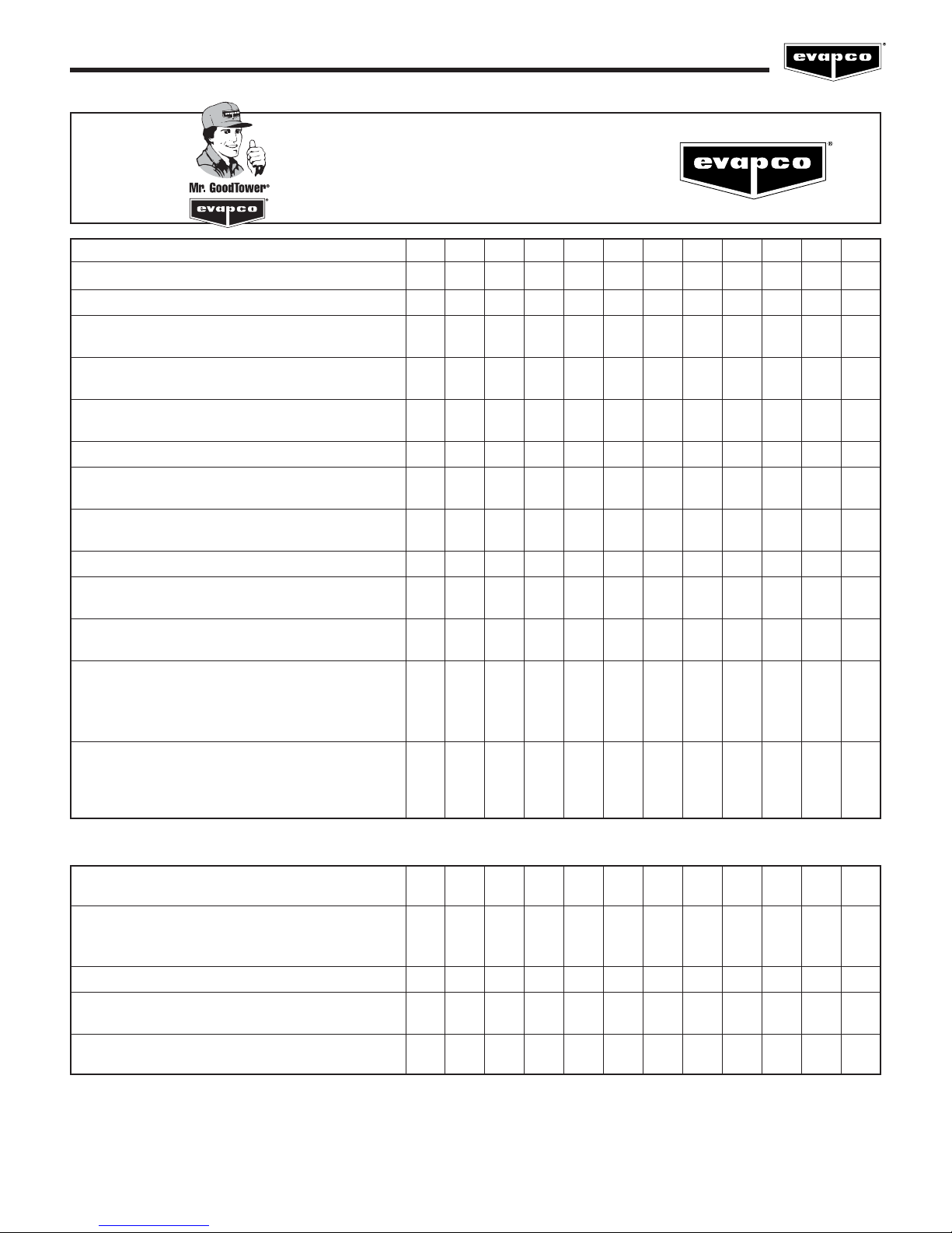
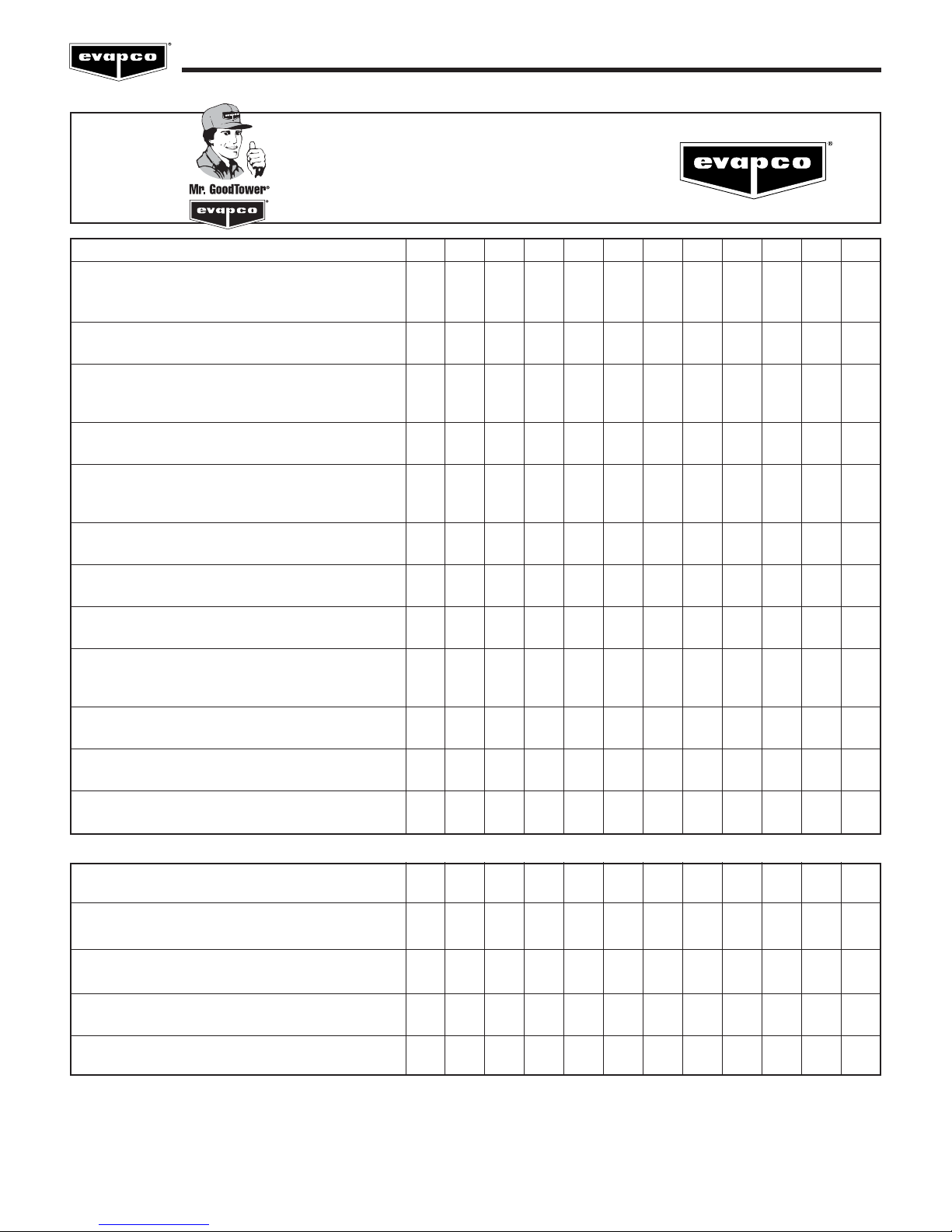
MAINTENANCE
CHECKLIST
PROCEDURE
1. Clean pan strainer – monthly or as needed
2. Clean and flush pan** – quarterly or as needed
3. Check bleed-off valve to make sure it is
operative – monthly
4. Check operating level in pan and adjust float
valve if necessary – monthly
5. Check water distribution system and spray
pattern – monthly
6. Check drift eliminators – quarterly
7. Check the fan blades for cracks, missing
balancing weights, and vibrations – quarterly
8. Lubricate fan shaft bearings* – every 1000
hours of operation or every three months
9. Check belt tension and adjust – monthly
10. Sliding motor base – Inspect and grease –
annually or as needed
11. Check fan screens, inlet louvers and fans.
Remove any dirt or debris – monthly
12. Inspect and clean protective finish – annually
- Galvanized: scrape and coat with ZRC
- Stainless: clean and polish with a
stainless steel cleaner.
13. Check water quality for biological contamination.
Clean unit as needed and contact a water
treatment company for recommended water
treatment program** – regularly
JAN FEB MAR APR MAY JUN JUL AUG SEP OCT NOV DEC
OPTIONAL ACCESSORIES:
1. Gear Reducer – Check oil level with unit
stopped – 24 hours after start-up & monthly
2. Gear Reducer/Piping – Do visual inspection
for oil leaks, auditory inspection for unusual
noises and vibrations – monthly
3. Gear Reducer - Replace oil – semi-annually
4. Oil Pump – Do visual inspection for leaks and
proper wiring – monthly
5. Gear Reducer/Coupling – Check alignment of
the system – 24 hours after start-up & monthly
* See maintenance manual for start-up instructions and lubrication recommendations.
** Cooling Towers must be cleaned on a regular basis to prevent the growth of bacteria including Legionella Pneumophila.
5
Operation and Maintenance Instructions
MAINTENANCE
CHECKLIST
OPTIONAL ACCESSORIES:
6. Coupling/Shaft – Inspect flex elements and
hardware for tightness, proper torque &
crack/deterioration – monthly
7. Heater Controller – Inspect controller and
clean probe ends – quarterly
8. Heater – Inspect junction box for loose wiring
and moisture – one month after start-up and
semi-annually
9. Heater – Inspect elements for scale
build-up – quarterly
10. Electronic Water Level Controller – Inspect
junction box for loose wiring and moisture –
semi-annually
11. Electronic Water Level Controller – Clean
probe ends of scale build-up – quarterly
12. Electronic Water Level Controller –Clean
inside the standpipe – annually
13. Solenoid Make-up Valve – Inspect and clean
valve of debris – as needed
14. Vibration Switch (mechanical) – Inspect
enclosure for loose wiring and moisture –
one month after start-up and monthly
15. Vibration Switch – Adjust the sensitivity –
during start-up and annually
16. Sump Sweeper Piping – Inspect and clean
piping of debris – semi-annually
17. Water Level Indicator – Inspect and clean –
annually
JAN FEB MAR APR MAY JUN JUL AUG SEP OCT NOV DEC
DURING IDLE PERIODS:
1. Few Days: Energize motor space heaters
– when motor is idle
2. Few Weeks: Run gear reducer for 5 minutes
– weekly
3. Several Weeks: Completely fill gear reducer
with oil. Drain to normal level prior to running.
4. One Month or longer: Rotate motor shaft/fan
10 turns – bi-weekly
5. One Month or longer: Megger test motor
windings – semi-annually
6

Operation and Maintenance Instructions
Seasonal Shut-Down Checklist
When the system is to be shut down for an extended period of time, the following services should be performed.
1. The evaporative cooling unit should be drained.
2. The cold water basin should be flushed and cleaned with the suction strainer screens in place.
3. The suction strainer screens should be cleaned and re-installed.
4. The cold water basin drain should be left open.
5. The fan shaft bearings and motor base adjusting screws should be lubricated.
6. The water make up valve needs to be closed. All water make-up piping needs to be drained, if not heat traced and
insulated.
7. The finish of the unit should be inspected. Clean and refinish as required.
8. The fan bearings and motor bearings need to be turned at least once a month by hand. This can be accomplished by
making sure the unitʼs disconnect is locked and tagged out, and grasping the fan assembly, rotating it several turns.
9. Energize motor space heaters.
Fan System
The fan systems of both centrifugal and axial driven units are rugged, however, the fan system must be checked regularly and
lubricated at the proper intervals. The following maintenance schedule is recommended.
Fan Motor Bearings
EVAPCO evaporative cooling units use either a T.E.A.O. (Totally Enclosed Air Over) or a T.E.F.C. (Totally Enclosed Fan Cooled) fan
motor. These motors are built to “Cooling Tower Duty” specifications. They are supplied with permanently lubricated bearings and
special moisture protection on the bearings, shaft and windings. After extended shut-downs, the motor should be checked with an
insulation tester prior to restarting the motor.
Fan Shaft Ball Bearings
Lubricate the fan shaft bearings every 1,000 hours of operation or every three months for induced draft units. Lubricate the fan
shaft bearings every 2,000 hours of operation or every six months for forced draft units. Use any of the following synthetic
waterproof, polyurea inhibited greases which are suitable for operation between -20°F and 350°F. (For colder operating
temperatures, contact the factory).
Mobil – Polyrex EM Chevron - SRI
Feed grease slowly into the bearings or the seals may be damaged. A hand grease gun is recommended for this process.
When introducing a new grease, all grease should be purged from the bearings.
All EVAPCO units are supplied with extended grease lines to allow easy lubrication of the fan shaft bearings.
7
Operation and Maintenance Instructions
Unit Description Location of Lube Line Fittings
Induced Draft Units: Located just beside the fan casing
6', 8', 8.5', 12', 15' and 17' wide access door
Induced Draft Units: Located inside the fan casing
All Others access door
LSTB Forced Draft Units Located on the front of the unit
LPT Forced Draft Units Located on the front of the unit
LSTA 4' Wide Forced Draft Units See Below
Tab l e 1 - Location of Grease Lube Line Fittings for Belt Driven Units.
Please note, the removal of the fan screens is not necessary on forced draft units to access the extended lube line fittings.
Fan Shaft Sleeve Bearings – (4ʼ wide LSTA units only)
Lubricate the intermediate sleeve bearing(s) before unit start up. The reservoir should be checked several times during the first
week to ensure that the oil reserve is brought to full capacity. After the first week of operation, lubricate the bearing(s) every 1,000
hours of operation or every three months (whichever occurs first). High temperatures or poor environmental conditions may
necessitate more frequent lubrication. The oil reservoir consists of a large felt packed cavity within the bearing housing. It is not
necessary to maintain the oil level within the filler cup.
Use one of the following industrial grade, non-detergent mineral oils. Do not use a detergent based oil or those designated
heavy duty or compounded. Different oils may be required when operating at temperatures below 30°F continuously. Table 2
provides a short list of approved lubricants for each temperature range. Most automotive oils are detergent based and may not be
used. Detergent oils will remove the graphite in the bearing sleeve and cause bearing failure.
Ambient Temp Texaco Drydene Exxon
30°F to 100°F Regal R&O 220 Paradene 220 Terrestic 220
-25°F to 30°F Capella WF 32 Refrig. Oil 3G ------------------
Tab l e 2 - Sleeve Bearing Lubricants
All bearings used on EVAPCO equipment are factory adjusted and self aligning. Do not disturb bearing alignment by tightening the
sleeve bearing caps.
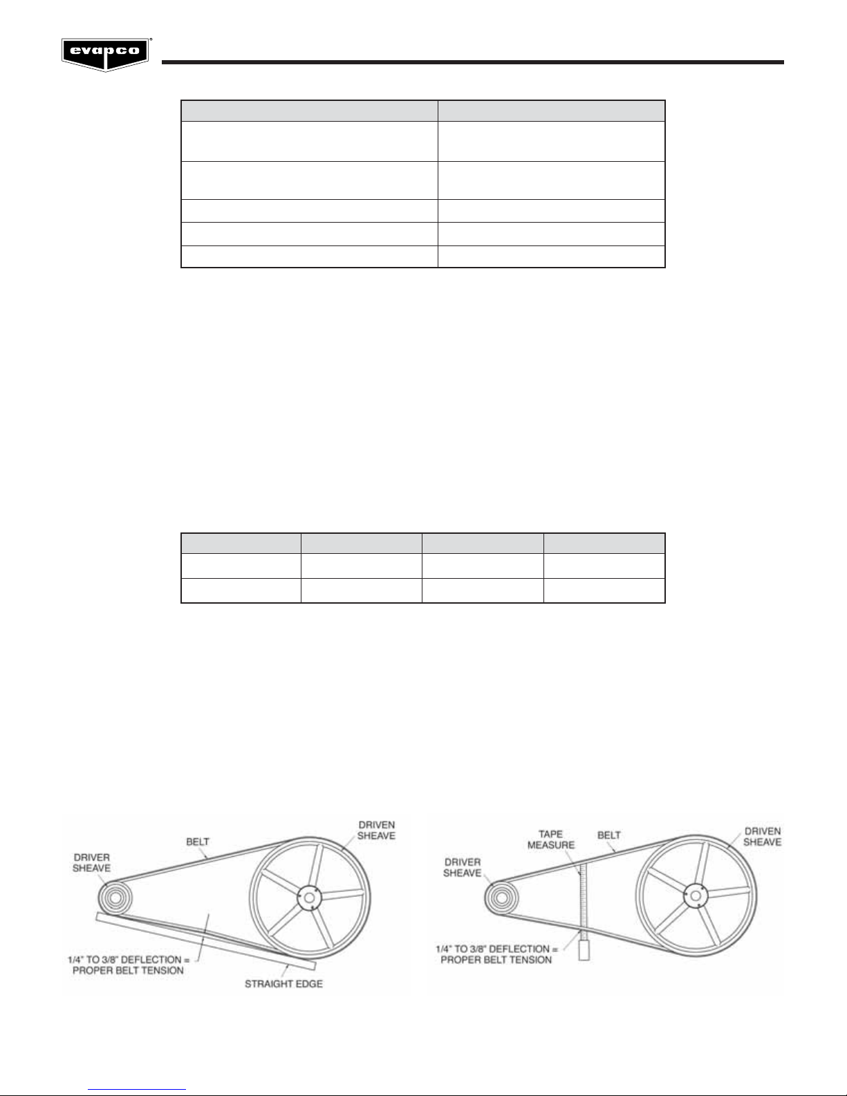
Fan Belt Adjustment
The fan belt tension should be checked at start up and again after the first 24 hours of operation to correct for any initial stretch. To
properly adjust the belt tension, position the fan motor so that the fan belt will deflect approximately 1/2” when moderate pressure
is applied midway between the sheaves. Figure 1 and Figure 2 show two ways to measure this deflection. Belt tension should be
checked on a monthly basin. A properly tensioned belt will not “chirp” or “squeal” when the fan motor is started.
Figure 1 – Method 1
Figure 2 – Method 2
8
Operation and Maintenance Instructions
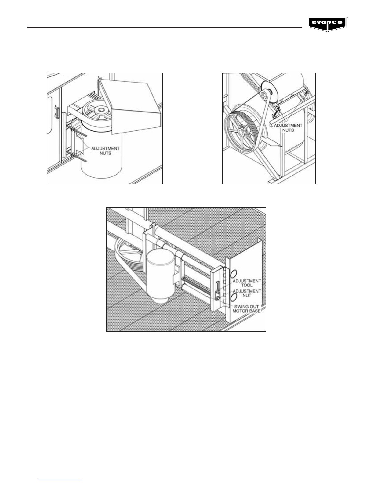
On induced draft belt driven units provided with externally mounted motors (6, 8, 8.5, 12, 15 and 17 foot wide units), Figure 3, and
LSTB forced draft units, Figure 4, both J-type adjustment bolts on the adjustable motor base should have an equal amount of
exposed thread for proper sheave and belt alignment.
Figure 3 – Externally Mounted Motors
Figure 5 – Internally Mounted Motors
On induced draft belt driven units with internally mounted motors (10, 12, 14, 20, 24 and 28 foot wide units), Figure 5, and LPT units,
Figure 6, a motor adjustment tool is provided. The tool will be found on the adjustment nut. To use, place the hex end over the
adjustment nut. Tension the belt by turning the nut counterclockwise. When the belts are properly tensioned, tighten the lock nut.
Figure 4 – LSTB Externally Mounted Motor
9

Operation and Maintenance Instructions
Figure 6 – LPT Motor Adjustment
Direct drive fan units do not require any adjustment (4' Wide Induced Draft ICT Models Only).
Fan System — Capacity Control
There are several methods for capacity control of the evaporative cooling unit. Methods include: Fan motor cycling, the use of two
speed motors and the use of variable frequency drives (VFDʼs). In all cases, if motors are idle for extended periods of time with
water still being directed over heat transfer media, motor space heaters are suggested.
Fan Motor Cycling
Fan Motor Cycling requires the use of a single stage thermostat which senses the water temperature. The contacts of the
thermostat are wired in series with the fan motorʼs starter holding coil.
Fan Motor Cycling is often found to be inadequate where the load has a wide fluctuation. In this method, there are only two stable
levels of performance: 100% of capacity when the fan is on and approximately 10% of capacity when the fan is off. Please note,
rapid cycling of the fan motors can cause the fan motor to overheat. Controls should be set to only allow a maximum of six (6)
start/stop cycles per hour.
Two Speed Motors
The use of a two speed motor provides an additional step of capacity control when used with the fan cycling method. The low
speed of the motor will provide 60% of full speed capacity.
Two speed capacity control systems require not only a two speed motor, but a two stage thermostat and the proper two speed
motor starter. The most common two speed motor is a single winding type. This is also known as a consequent pole design. Two
speed two winding motors are also available. All multi-speed motors used in evaporative cooling units should be variable torque
design.
It is important to note that when two speed motors are to be used, the motor starter controls must be equipped with a decelerating
time delay relay. The time delay should be a minimum of a 30 second delay when switching from high speed to low speed.
10
Operation and Maintenance Instructions
Sequence of Operation for Two Fan Units with Two Speed Motors During Peak Load
1. Both fan motors on full speed – full water flow over both cells
2. One fan motor on high speed, one fan motor on low speed – full water flow over both cells
3. Both fan motors on low speed – full flow over both cells
4. One fan motor on low speed, one fan motor off – full water flow over both cells
5. Both fan motors off – full water flow over both cells
6. Both fan motors off – full single cell flow through one cell
Variable Frequency Drives
The use of a variable frequency drive (VFD) provides the most precise method of capacity control. A VFD is a device that converts
a fixed AC voltage and frequency and changes it into an AC adjustable voltage and frequency used to control the speed of an AC
motor. By adjusting the voltage and frequency, the AC induction motor can operate at many different speeds.
The use of VFD technology can also benefit the life of the mechanical components with fewer and smoother motor starts and built
in motor diagnostics. VFD technology has particular benefit on evaporative cooling units operating in cold climates where airflow
can be modulated to minimize icing and reversed at low speed for de-icing cycles. Applications using a VFD for capacity control
must also use an inverter duty motor built in compliance with NEMA standard MG-1. This is an available option from EVAPCO. The
standard fan motors supplied by EVAPCO are not intended for use with VFDʼs.
The type of motor, manufacturer of the VFD, motor lead lengths (between the motor and the VFD), conduit runs and grounding can
dramatically affect the response and life of the motor. The motor lead length restrictions vary with the motor vendor. Regardless of
motor supplier, minimizing motor lead length between the motor and the drive is good practice.
Sequence of Operation for Multi-fan Units with a VFD During Peak Load
1. The VFDs should all be synchronized to speed up and slow down uniformly.
2. The VFDs need to have a pre-set shutoff to prevent water temperatures from becoming too cold and to prevent the drive
from trying to turn the fan at near zero speed.
3. Operating below 25% of motor speed achieves very little return in fan energy savings and capacity control. Check with
your VFD supplier if operating below 25% is possible.
For more details on the use of variable frequency drives, please request copies of EVAPCOʼs Engineering Bulletins 39 and 43.
11
Operation and Maintenance Instructions
Recirculated Water System – Routine Maintenance
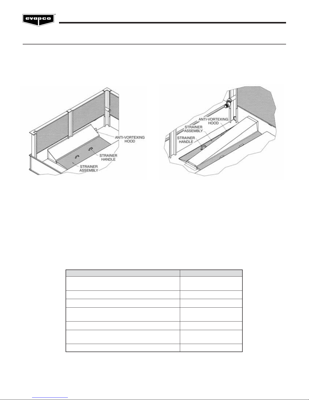
Suction Strainer in Cold Water Basin
The pan strainer should be removed and cleaned monthly or as often as necessary. The suction strainer is the first line of defense
in keeping debris out of the system. Make certain that the strainer is properly located over the pump suction, alongside the antivortexing hood.
Figure 7 – Single Strainer Assembly
Figure 8 – Dual Strainer Assembly
Cold Water Basin
The cold water basin should be flushed out quarterly, and checked monthly or more often if necessary, to remove any accumulation
of dirt or sediment which normally collects in the basin. Sediment can become corrosive and cause deterioration of basin materials.
When flushing the basin, it is important to keep the suction strainers in place to prevent any sediment from entering the system.
After the basin has been cleaned, the strainers should be removed and cleaned before refilling the basin with fresh water.
Operating Level of Water in Cold Water Basin
The operating level should be checked monthly to make sure the water level is correct. Refer to Table 3 for unit specific levels.
Model Number OperatingDepth*
ICT 3-63 through 3-93 6”
ICT 4-54 through 4-912 7”
UBT 8-56B through 24-918B 9”
AT/USS 14-64 through 14-912 7”
AT/USS/UT 19-56 through 224-918 9”
AT/USS/UT 424-024 through 428-948 11”
LSTA 4-61 through 4-185 9”
LSTB 5112 through 8P536 9”
LSTB 10112 through 10636 13”
LPT 316 through 8812 8”
* Measured from lowest point on basin floor.
Tab l e 3 - Recommended Operating Water Level
12
 Loading...