

EVAPCO Eco-Air User Manual
EVAPCO Controller Users Manual
For eco-Air™Air Cooled and Adiabatic Fluid Coolers and Condensers
For EVAPCO Authorized Parts and Service, Contact Your Local EVAPCO
Representative or the Local Mr. GoodTower®Service Provider
Bulletin 1130
EVAPCO, Inc. — World Headquarters & Research/Development Center
EVAPCO North America
EVAPCO, Inc.
World Headquarters
P.O. Box 1300
Westminster, MD 21158 USA
Phone: 410-756-2600
Fax: 410-756-6450
E-mail: marketing@evapco.com
EVAPCO East
5151 Allendale Lane
Taneytown, MD 21787 USA
410-756-2600 p | 410-756-6450 f
marketing@evapco.com
EVAPCO East
Key Building
Taneytown, MD USA
410-756-2600 p
marketing@evapco.com
EVAPCO Midwest
Greenup, IL USA
217-923-3431 p
evapcomw@evapcomw.com
EVAPCO West
Madera, CA USA
559-673-2207 p
contact@evapcowest.com
EVAPCO Iowa
Lake View, IA USA
712-657-3223 p
EVAPCO Iowa
Sales & Engineering
Medford, MN USA
507-446-8005 p
evapcomn@evapcomn.com
EVAPCO Newton
Newton, IL USA
618-783-3433 p
evapcomw@evapcomw.com
EVAPCOLD
Greenup, IL USA
217-923-3431 p
evapcomw@evapcomw.com
EVAPCO, Inc. • P.O. Box 1300 • Westminster, MD 21158 USA
P
HONE: 410-756-2600 • FAX: 410-756-6450 • E-MAIL: marketing@evapco.com
EVAPCO Asia/Pacific
EVAPCO Asia/Pacific Headquarters
1159 Luoning Rd. Baoshan Industrial Zone
Shanghai 200949, P.R. China
Phone: (86) 21-6687-7786
Fax: (86) 21-6687-7008
E-mail:
EVAPCO (Shanghai) Refrigeration
Equipment Co., Ltd.
Baoshan Industrial Zone Shanghai, P.R. China
(86) 21-6687-7786 p
marketing@evapcochina.com
Beijing EVAPCO Refrigeration
Equipment Co., Ltd.
Huairou District Beijing, P.R. China
010-6166-7238 p
evapcobj@evapcochina.com
EVAPCO Australia (Pty.) Ltd.
Riverstone NSW 2765, Australia
(61) 2 9627-3322 p
sales@evapco.com.au
EVAPCO Composites Sdn. Bhd
Rawang, Selangor, Malaysia
(60-3) 6092-2209 p
EvapTech Asia Pacific Sdn. Bhd
A wholly owned subsidiary of EvapTech, Inc.
Puchong, Selangor, Malaysia
(60-3) 8070-7255 p
marketing-ap@evaptech.com
EVAPCO South America
EVAPCO Brasil
Equipamentos Industriais Ltda.
Al. Vênus, 151 – CEP: 13347-659
Indaiatuba –São Paulo – Brasil
(55+11) 5681-2000 p
vendas@evapco.com.br
Fan Technology Resource
Cruz das Almas – Indaiatuba
São Paulo, Brasil 13308-200
55 (11) 4025-1670
fantr@fantr.com
EVAPCO-BLCT Dry Cooling, Inc.
1011 US Highway 22 West
Bridgewater, NJ 08807 USA
Phone: 1-908-379-2665
E-mail: info@evapco-blct.com
EVAPCO-BLCT Dry Cooling, Inc.
7991 Shaffer Parkway
Littleton, CO 80127 USA
Phone: 1-908-379-2665
E-mail: info@evapco-blct.com
Spare Parts Phone: 908-895-3236
Spare Parts e-mail: spares@evapco-blct.com
EVAPCO Power México S. de R.L. de C.V.
Calle Iglesia No. 2, Torre E
Tizapan San Ángel, Del. Álvaro Obregón
Ciudad de México, D.F. México 01090
Phone: +52 (55) 8421-9260
e-mail: info@evapco-blct.com
Refrigeration Valves & Systems Corporation
A wholly owned subsidiary of EVAPCO, Inc.
Bryan, TX USA
979-778-0095 p
rvs@rvscorp.com
EvapTech, Inc.
A wholly owned subsidiary of EVAPCO, Inc.
Lenexa, KS USA
913-322-5165 p
marketing@evaptech.com
Tower Components, Inc.
A wholly owned subsidiary of EVAPCO, Inc.
Ramseur, NC USA
336-824-2102 p
mail@towercomponentsinc.com
EVAPCO Alcoil, Inc.
A wholly owned subsidiary of EVAPCO, Inc.
York, PA USA
717-347-7500 p
info@alcoil.net
EVAPCO Europe
EVAPCO Europe BVBA
European Headquarters
Heersteveldweg 19
Industrieterrein Oost
3700 Tongeren, Belgium
Phone: (32) 12-395029
Fax: (32) 12-238527
evapco.europe@evapco.be
E-mail:
EVAPCO Europe, S.r.l.
Milan, Italy
(39) 02-939-9041 p
evapcoeurope@evapco.it
EVAPCO Europe, S.r.l.
Sondrio, Italy
EVAPCO Europe GmbH
Meerbusch, Germany
(49) 2159 6956 18 p
info@evapco.de
EVAPCO Air Solutions
A wholly owned subsidiary of EVAPCO, Inc.
Aabybro, Denmark
(45) 9824 4999 p
info@evapco.dk
EVAPCO Air Solutions GmbH
Garbsen, Germany
(49) 5137 93875-0 p
info@evapcoas.de
Evap Egypt Engineering Industries Co.
A licensed manufacturer of EVAPCO, Inc.
Nasr City, Cairo, Egypt
2 02 24022866/2 02 24044997 p
primacool@link.net / shady@primacool.net
EVAPCO S.A. (Pty.) Ltd.
A licensed manufacturer of EVAPCO, Inc.
Isando 1600, Republic of South Africa
(27) 11-392-6630 p
evapco@evapco.co.za
marketing@evapcochina.com
EVAPCO...SPECIALISTS IN HEAT TRANSFER PRODUCTS AND SERVICES.
Visit EVAPCO’s Website at: www.evapco.com

Controller User Manual
Table of Contents
Introduction . . . . . . . . . . . . . . . . . . . . . . . . . . . . . . . . . . . . . . . . . . . . . . . . . . . . . . . . . . . . . . . . . . . . . . . . . . . . . . . . . . . . . . . . . . .3
EVAPCO Controller . . . . . . . . . . . . . . . . . . . . . . . . . . . . . . . . . . . . . . . . . . . . . . . . . . . . . . . . . . . . . . . . . . . . . . . . . . . . . . . . .3
Installation and Wiring . . . . . . . . . . . . . . . . . . . . . . . . . . . . . . . . . . . . . . . . . . . . . . . . . . . . . . . . . . . . . . . . . . . . . . . . . . . . . . . . . . . .3
Safety . . . . . . . . . . . . . . . . . . . . . . . . . . . . . . . . . . . . . . . . . . . . . . . . . . . . . . . . . . . . . . . . . . . . . . . . . . . . . . . . . . . . . . . . . . .3
Panel Installation Considerations . . . . . . . . . . . . . . . . . . . . . . . . . . . . . . . . . . . . . . . . . . . . . . . . . . . . . . . . . . . . . . . . . . . . . . .4
Temperature/Pressure Sensor Installation . . . . . . . . . . . . . . . . . . . . . . . . . . . . . . . . . . . . . . . . . . . . . . . . . . . . . . . . . . . . . . . .4
Wiring Considerations . . . . . . . . . . . . . . . . . . . . . . . . . . . . . . . . . . . . . . . . . . . . . . . . . . . . . . . . . . . . . . . . . . . . . . . . . . . . . . .6
Operation and Servicing . . . . . . . . . . . . . . . . . . . . . . . . . . . . . . . . . . . . . . . . . . . . . . . . . . . . . . . . . . . . . . . . . . . . . . . . . . . . . .6
Screen Navigation . . . . . . . . . . . . . . . . . . . . . . . . . . . . . . . . . . . . . . . . . . . . . . . . . . . . . . . . . . . . . . . . . . . . . . . . . . . . . . . . . . . . . . .7
Navigating the Display . . . . . . . . . . . . . . . . . . . . . . . . . . . . . . . . . . . . . . . . . . . . . . . . . . . . . . . . . . . . . . . . . . . . . . . . . . . . . . .7
Modifying a Value . . . . . . . . . . . . . . . . . . . . . . . . . . . . . . . . . . . . . . . . . . . . . . . . . . . . . . . . . . . . . . . . . . . . . . . . . . . . . . . . . . .8
Navigating the Scheduler . . . . . . . . . . . . . . . . . . . . . . . . . . . . . . . . . . . . . . . . . . . . . . . . . . . . . . . . . . . . . . . . . . . . . . . . . . . . .9
Operator Interface Screens . . . . . . . . . . . . . . . . . . . . . . . . . . . . . . . . . . . . . . . . . . . . . . . . . . . . . . . . . . . . . . . . . . . . . . . . . . . . . . .13
Welcome Screen . . . . . . . . . . . . . . . . . . . . . . . . . . . . . . . . . . . . . . . . . . . . . . . . . . . . . . . . . . . . . . . . . . . . . . . . . . . . . . . . . .13
Standby Status Screens . . . . . . . . . . . . . . . . . . . . . . . . . . . . . . . . . . . . . . . . . . . . . . . . . . . . . . . . . . . . . . . . . . . . . . . . . . . . .13
Alarms Screen . . . . . . . . . . . . . . . . . . . . . . . . . . . . . . . . . . . . . . . . . . . . . . . . . . . . . . . . . . . . . . . . . . . . . . . . . . . . . . . . . . . .16
Main Menu Screen . . . . . . . . . . . . . . . . . . . . . . . . . . . . . . . . . . . . . . . . . . . . . . . . . . . . . . . . . . . . . . . . . . . . . . . . . . . . . . . . .17
On/Off Unit Screen . . . . . . . . . . . . . . . . . . . . . . . . . . . . . . . . . . . . . . . . . . . . . . . . . . . . . . . . . . . . . . . . . . . . . . . . . . . . . . . . .17
View Setpoints Screen . . . . . . . . . . . . . . . . . . . . . . . . . . . . . . . . . . . . . . . . . . . . . . . . . . . . . . . . . . . . . . . . . . . . . . . . . . . . . .18
Clock/Scheduler Screens . . . . . . . . . . . . . . . . . . . . . . . . . . . . . . . . . . . . . . . . . . . . . . . . . . . . . . . . . . . . . . . . . . . . . . . . . . . .18
Input/Output Screens . . . . . . . . . . . . . . . . . . . . . . . . . . . . . . . . . . . . . . . . . . . . . . . . . . . . . . . . . . . . . . . . . . . . . . . . . . . . . . .20
Error Log Screen . . . . . . . . . . . . . . . . . . . . . . . . . . . . . . . . . . . . . . . . . . . . . . . . . . . . . . . . . . . . . . . . . . . . . . . . . . . . . . . . . .21
Board Switch Screen . . . . . . . . . . . . . . . . . . . . . . . . . . . . . . . . . . . . . . . . . . . . . . . . . . . . . . . . . . . . . . . . . . . . . . . . . . . . . . .21
Service Screens . . . . . . . . . . . . . . . . . . . . . . . . . . . . . . . . . . . . . . . . . . . . . . . . . . . . . . . . . . . . . . . . . . . . . . . . . . . . . . . . . . .22
Manufacturer Screens . . . . . . . . . . . . . . . . . . . . . . . . . . . . . . . . . . . . . . . . . . . . . . . . . . . . . . . . . . . . . . . . . . . . . . . . . . . . . .40
Terminology . . . . . . . . . . . . . . . . . . . . . . . . . . . . . . . . . . . . . . . . . . . . . . . . . . . . . . . . . . . . . . . . . . . . . . . . . . . . . . . . . . . . . . . . . .41
Alarm Event Description . . . . . . . . . . . . . . . . . . . . . . . . . . . . . . . . . . . . . . . . . . . . . . . . . . . . . . . . . . . . . . . . . . . . . . . . . . . . . . . . .42
2

Controller User Manual
Introduction
EVAPCO Controller
Congratulations on the purchase of your eco-Air unit with the EVAPCO Controller. The EVAPCO Controller will ensure that your
eco-Air unit is operating in the most efficient manner possible while using minimal resources. Along with proper eco-Air unit
maintenance, the EVAPCO Controller will ensure that your eco-Air unit provide years of service at peak efficiency.
The EVAPCO Controller serves as a single connection point for the eco-Air unit and contains all of the protection and logic devices
required to run the eco-Air unit in the most efficient manner possible.
In order to reduce downtime, Evapco recommends keeping a stock of spare fuses. Consult the wiring diagram for the quantity,
type, and fuse size required. Contact your local EVAPCO representative for replacement or spare parts.
This bulletin includes a description of the screens and parameters that are available through the display located on the front of the
EVAPCO Controller. Also included in this bulletin are the functions of the EVAPCO Controller. Please note that the screens
displayed on your EVAPCO Controller display may vary slightly from the images shown in this document.
Become familiar with the EVAPCO Controller by thoroughly reading and understanding the content of this bulletin. A detailed wiring
diagram can be found in the data pocket inside of the EVAPCO Controller.
If you should require any additional information about the operation or maintenance of this equipment, contact your local EVAPCO
representative. You may also visit www.evapco.com for more information.
Installation and Wiring
Safety
Qualified personnel should use proper care, procedures, and tools when operating, maintaining, or repairing this equipment or any
other connected equipment in order to prevent personal injury and/or property damage. The warnings listed below are to be used
as guidelines only.
Warning: EVAPCO eco-Air units should never be operated without fan screens and access doors properly secured and
in place.
Warning: Avoid working on electrical circuits while they are live. Proper lock-out/tag-out and all applicable safety
practices must be followed prior to servicing any equipment.
Warning: Before opening the panel door, allow sufficient time for VFD’s to discharge after removing power. VFD’s contain
capacitive circuits which maintain a charge even after power is removed.
Warning: The three position selector switch is not intended to replace or act as a disconnect to disable the EVAPCO
eco-Air unit and/or de-energize the EVAPCO Controller. Be sure to follow lock-out/tag-out and all applicable
electrical safety practices before servicing any equipment.
Warning: Do not attempt to service or enter the eco-Air unit even if the unit status is indicated as being off. Unless power is
completely removed from the eco-Air unit, it may be possible for the eco-Air unit to start at any time without notice.
Be sure to follow lock-out/tag-out and all applicable electrical safety practices before servicing any equipment.
3
Controller User Manual
The following safety issues need to be addressed by those responsible for the installation, maintenance, and repair of the EVAPCO
Controller:
Access to the control panel (including the disconnect switch(es)).
•
• Sizing and protection of electrical circuits feeding the control panel(s) and branch circuits feeding the controlled equipment.
• Proper grounding of electrical circuits.
• Qualification of persons who will install, maintain, and service the electrical equipment.
Panel Installation Considerations
When the EVAPCO Controller does not ship factory mounted on the eco-Air unit, the EVAPCO Controller should be placed in close
proximity to the eco-Air unit to reduce the wire lengths required. If the EVAPCO Controller is within sight of or mounted on the ecoAir unit, the EVAPCO Controller may be used as the main electrical disconnect for the eco-Air unit. Otherwise, separate electrical
disconnects may be required. Consult applicable electrical codes to make this determination. Avoid mounting the EVAPCO
Controller with a southern exposure. This will minimize the amount of solar heat gain the system will experience and will make it
easier to view the operator interface.
Temperature/Pressure Sensor Installation
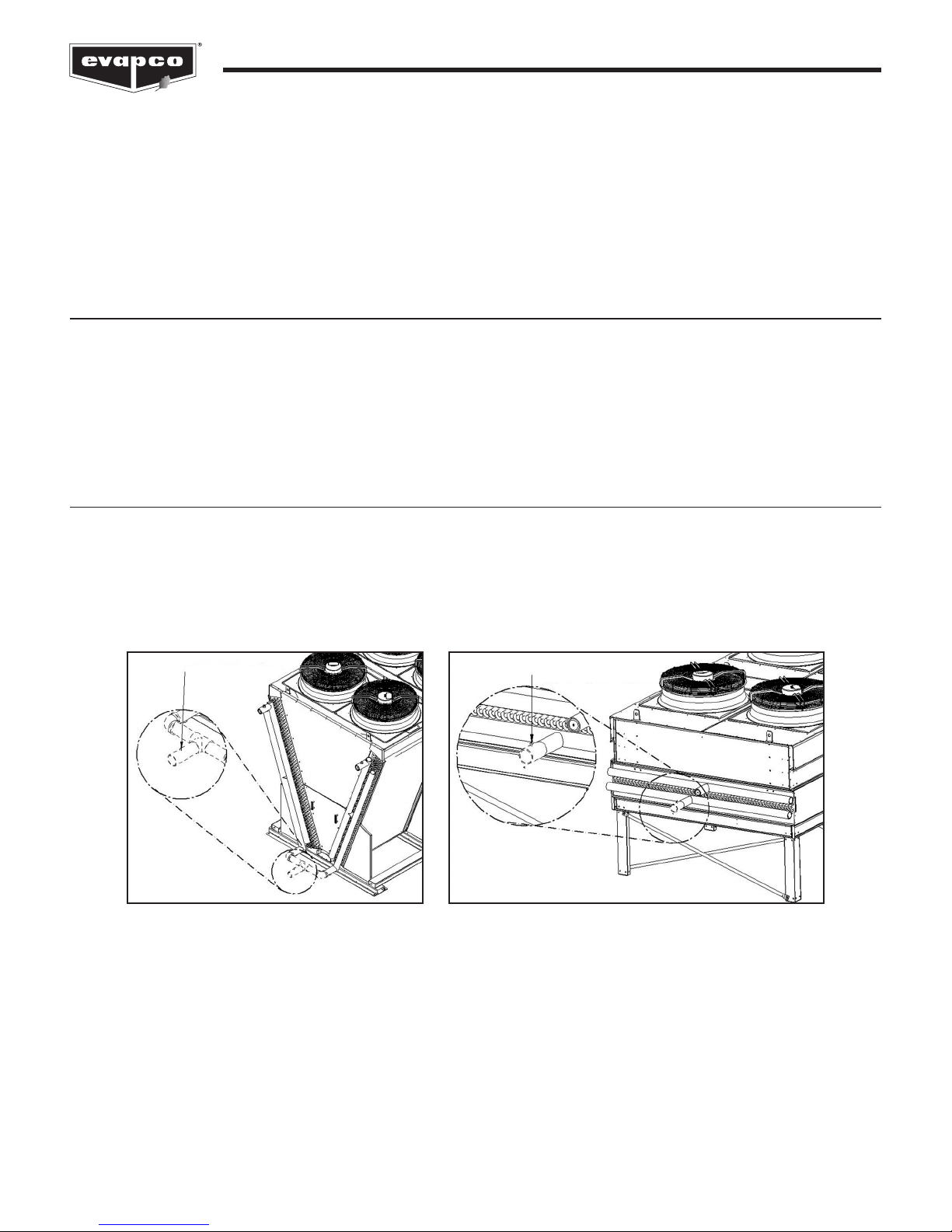
EVAPCO eco-Air fluid coolers are supplied with a thermowell (1/4” G threads) and a NTC temperature sensor. The thermowell and
temperature sensor should be installed in the common return pipework of the eco-Air fluid cooler unit. Thermowells must be
installed in the horizontal sections of the coil piping. A small amount of thermal paste should be added to the thermowell before the
NTC sensor is inserted to ensure a more accurate fluid temperature measurement.
TEMPERATURE SENSOR
TEMPERATURE SENSOR
Figure 1
The suggested temperature sensor location for fluid coolers. Piping shown by dashed lines provided and installed by others.
4
Controller User Manual
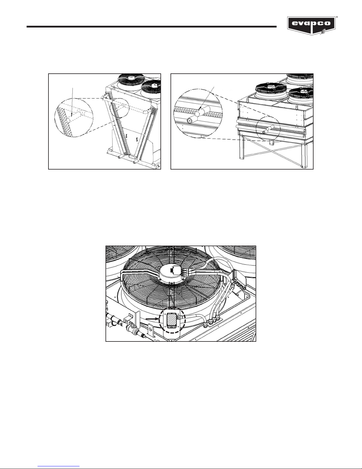
EVAPCO eco-Air condensers are supplied with a pressure transducer (7/16”-20 UNF threads). The pressure transducer should be
located in the common compressor hot gas discharge pipework. It is recommended that a shut-off valve be located between the
ipework and the pressure transducer to allow the transducer to be more easily replaced should it become damaged.
p
RESSURE SENSOR
P
PRESSURE SENSOR
Figure 2
The suggested pressure sensor location for condensers. Piping shown by dashed lines provided and installed by others.
When the EVAPCO Controller ships factory mounted to the eco-Air unit, the supplied temperature or pressure sensor must be
wired to the junction box location on the connection end of the eco-Air unit (Figure 3). If the EVAPCO Controller does not ship
factory mounted, the supplied temperature or pressure sensor must be wired to the EVAPCO Controller. Consult the supplied
wiring diagram for a determination if the junction box is supplied.
Each EVAPCO Controller is supplied with one ambient air sensor that is located on the bottom of the Controller enclosure. Should
the EVAPCO Controller be placed in a location where the ambient temperature (i.e. indoors) is not indicative of the ambient
temperature of the eco-Air unit, the ambient temperature sensor must be relocated to a more suitable location and the resulting
opening in the enclosure must be sealed with a Type 4 plug.
Figure 3
The junction box is highlighted and circled.
5

Controller User Manual
Wiring Considerations
Consult the supplied wiring diagram for detailed wiring information. All field wiring is indicated by dashed lines on the wiring
diagram.
All wiring in and out of the EVAPCO Controller should be with copper conductors and wire lengths must be kept as short as
ossible. Consult the detailed wiring diagram for field wiring connections of each device. Applicable electrical codes for the
p
location should be followed during the sizing and installation of the field wiring. All fittings attached to the EVAPCO Controller
must be Type 4. All wiring must be through the bottom of the EVAPCO Controller. Top entry into the EVAPCO Controller is
not permitted. Any damage caused to any component within or connected to the EVAPCO Controller due to a top entry
connection is not warrantable!
®
For wiring the EVAPCO Controller to each NEMA fan motor, Belden
be used. The shield of the VFD cable needs to be bonded to ground at both ends of the cable.
While the EVAPCO Controller does provide provisions for connection to a BAS, this connection is not required for the EVAPCO
Controller to operate.
Operation and Servicing
On eco-Air units equipped with NEMA fan motor(s), the EVAPCO Controller contains a three position selector switch (Bypass-OffAuto) located behind the HMI door. The operation of each position is as follows:
VFD cable 295XX (XX denotes gauge) or equivalent should
Auto:
The Auto position allows the EVAPCO Controller to operate the eco-Air unit based on the logic programmed into the
Controller. Note that the unit must be switched on before the eco-Air unit will begin to operate. Please see the On/Off Unit
Screen section of this document for more information.
In the Off position, the EVAPCO Controller will be powered; however, output commands will not be sent to any of the
Off:
attached equipment. This position is used for programming the VFD.
Bypass:
In the Bypass position, the logic program is bypassed which allows the fan motor(s) to energize independent of
sensor temperature or setpoints. Power is routed around the VFD and thus the fan motor(s) will operate at full power, acrossthe-line. The VFD will still be energized when the selector switch is in the Bypass position.
The door protecting the HMI must be shut unless an operator is using the HMI interface. This will protect the HMI interface from
contamination and increase the life of the HMI.
The EVAPCO Controller is supplied with air filters that must be inspected every 90 days. Depending on the installation
environment, more frequent inspection and/or replacement may be required. A dirty filter can cause the internal panel temperature
to increase and may cause component failure. Permanently removing the filter will allow dirt and particulates to enter the enclosure
and may cause premature failure.
Please consult the proper Operation and Maintenance Instructions for start-up and maintenance guides for the eco-Air unit
attached to the EVAPCO Controller.
6
Controller User Manual
Screen Navigation
Navigating the Display
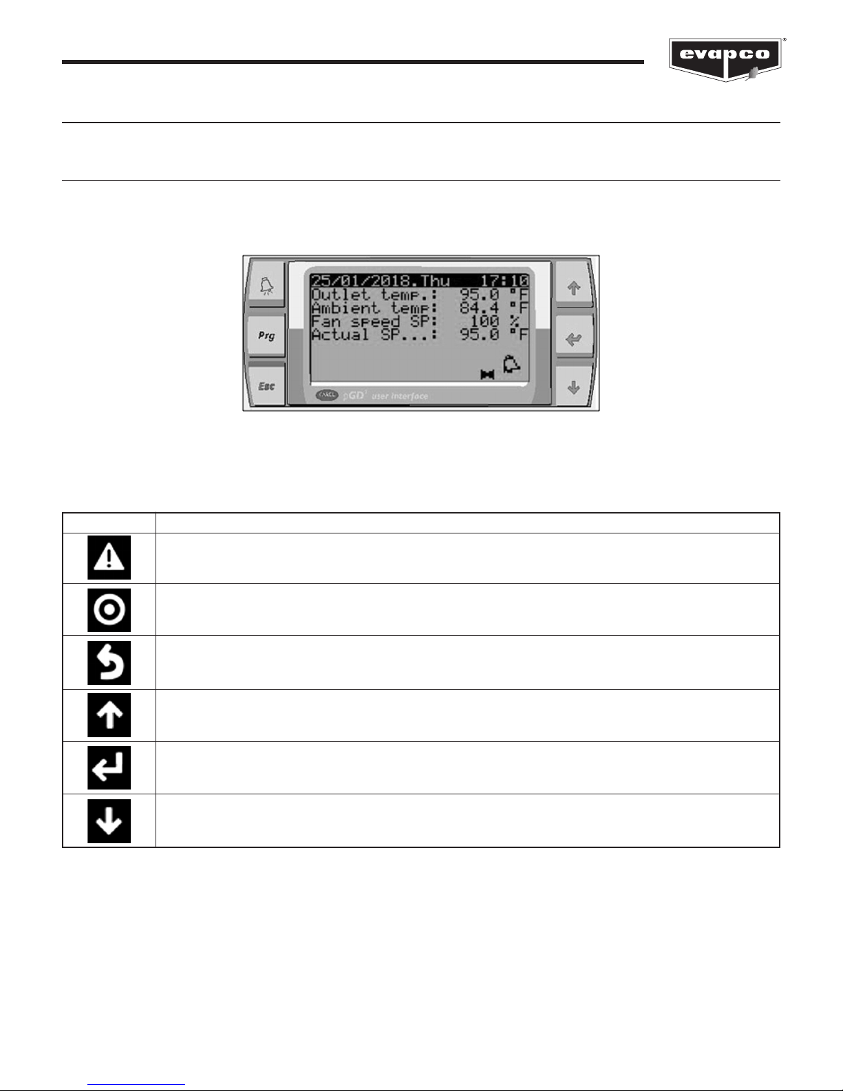
The operator interface contains a LED display and six buttons that allow the user to navigate the various screens as well as view
and modify several setpoints that affect the operation of the eco-Air unit.
Figure 4
The operator interface of the EVAPCO Controller.
Button Function
ALARM button. Direct shortcut to the Alarms Screen. This button will flash red if there is an active alarm.
PRG button (Program). Direct shortcut to the Main Menu Screen.
ESC button. Leaves a menu or an entry field without changing the value.
UP button. Scrolls up in the menu or changes a value.
ENT button. Goes to the selected submenu or accepts a modified value.
DOWN button. Scrolls down in the menu or changes a value.
Table 1
A description of the buttons located on the operator interface.
7

Controller User Manual
Active Alarms
Pre-Cooling Stage Rotation Screen
Flush Timer Screen
Pre-Cooling Minimum On Time Screen
Pre-Cooling Increment/Decrement Screen
Fan Motor Status Screen
Alarms Screen
Standby Screen
Standby Status Screens Main Menu Screens
A. On/Off Unit
B. View Setpoints
C. Clock/Scheduler
D. Input/Output
E. Error Log
F. Board Switch
G. Service
H. Manufacturer
Figure 5 provides an overview of the various screens and menus of the EVAPCO Controller.
Figure 5
Controller screen flowchart.
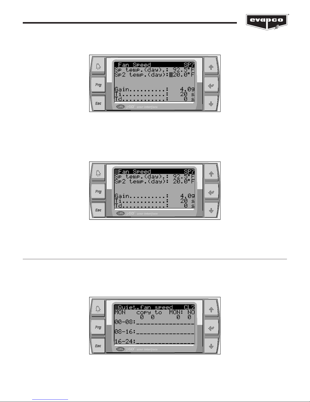
Modifying a Value
To change a parameter on a given screen, first navigate to the desired screen. In this example, the setpoint temperature will be
modified. Once at the desired screen, press the ENT button.
Figure 6
The cursor next to the setpoint temperature.
8
Controller User Manual
As seen in Figure 6, the cursor (the shaded block) is next to the setpoint value. To change the value, press the UP or DOWN
button. To accept the value, press the ENT button.
Figure 7
The cursor moved to the next setpoint. Note that the first setpoint value has changed.
Next, press the ESC button to return to the previous menu or repeatedly press the ENT button until the cursor moves to the top of
the screen.
Figure 8
The cursor is located in the top left of the screen.
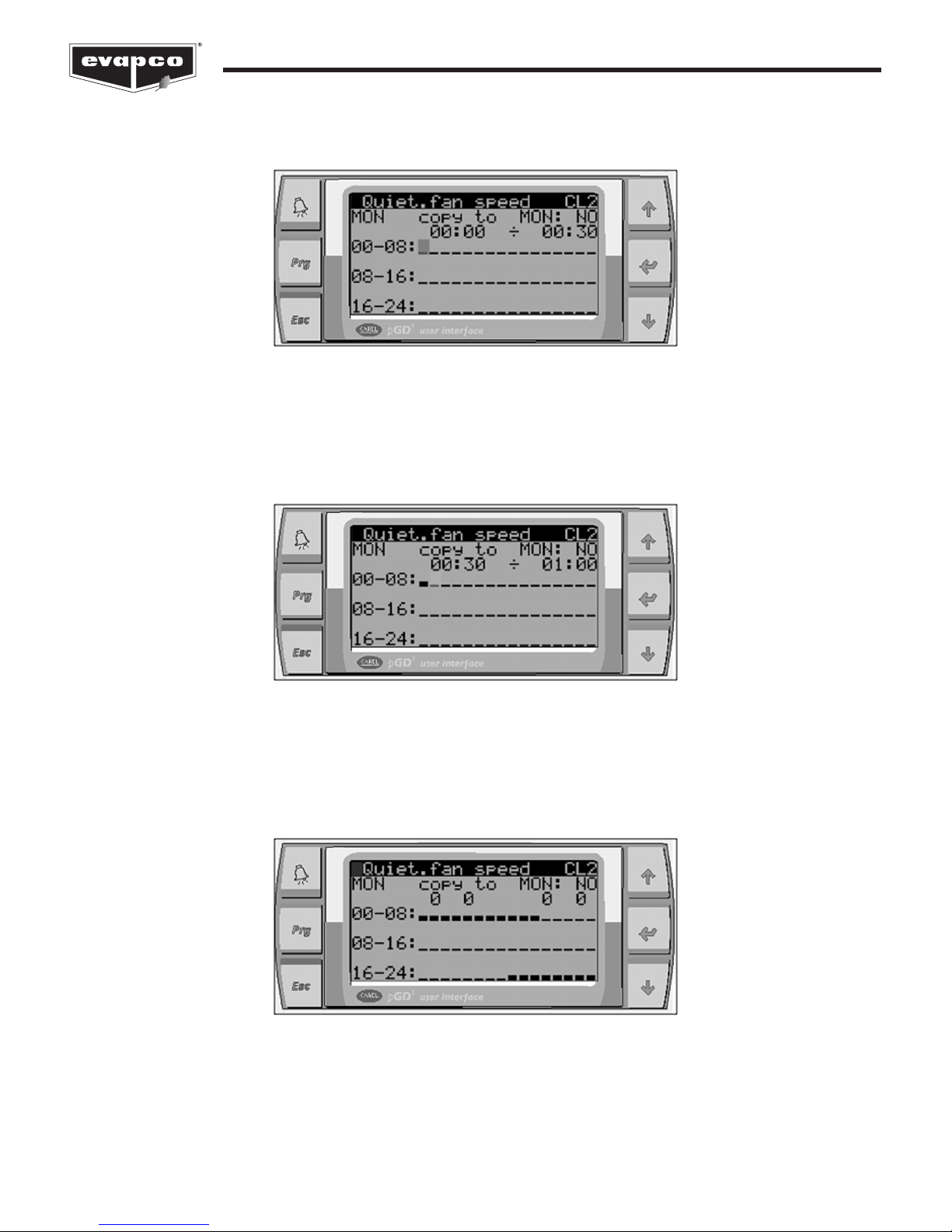
Navigating the Scheduler
Several functions of the EVAPCO Controller are able to be scheduled to operate during certain periods of the year or at certain
times of the day. In this example, consider a noise restriction from 8:00pm to 5:30am starting Sunday night and ending Friday
morning. During the noise restriction hours, the fan speed will be limited to 85% via the Quiet Mode. After navigating to the proper
scheduler, the screen shown in Figure 9 will be displayed. The day of the week is indicated in the upper left corner.
Figure 9
The Scheduler Screen.
9
Controller User Manual
Each block represents a half hour period of time. First, press the ENT button four times until the first block is highlighted by the
cursor. Note that this first block represents 12:00am to 12:30am.
Figure 10
The 12:00am to 12:30am block is selected.
Press the UP or DOWN button to enable the Quiet Mode during the selected period of time. The selected block will become raised
indicating that the Quiet Mode will be active. Press the ENT button to move to the next half hour period (12:30am to 1:00am).
Figure 11
Quiet Mode will be active from 12:00am to 12:30am.
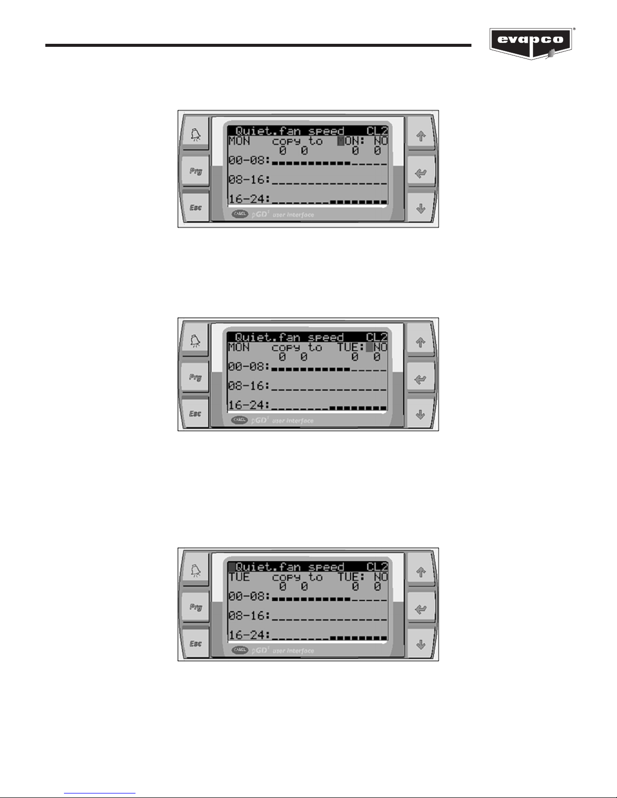
Continue the steps above until the desired blocks are raised. As shown in Figure 12, the Quiet Mode will be active from 12:00am to
5:30 am and 8:00pm to 12:00am on Monday.
Figure 12
Quiet Mode is active from 12:00am to 5:30am and 8:00pm to 12:00am on Monday.
10
Controller User Manual
This schedule for Monday now may be copied to the other days of the week. Press the ENT button to place the cursor after the
copy to text shown on the display.
Figure 13
The day to copy to the current schedule to is highlighted by the cursor.
Use the UP button to change the copy to date to Tuesday and press the ENT button.
Figure 14
After Selecting YES, Monday’s schedule will be copied to Tuesday.
Next, use the UP or DOWN button to change the NO to YES and press the ENT button. After a few seconds, the YES will change
back to a NO, indicating that the copy was successful. Place the cursor next to the text that says MON. Press the UP or DOWN
button to change the day to TUE, and press the ENT button. The scheduler for Tuesday should be identical to Monday.
Figure 15
Tuesday’s schedule is now the same as Monday after the copy.
11
Controller User Manual
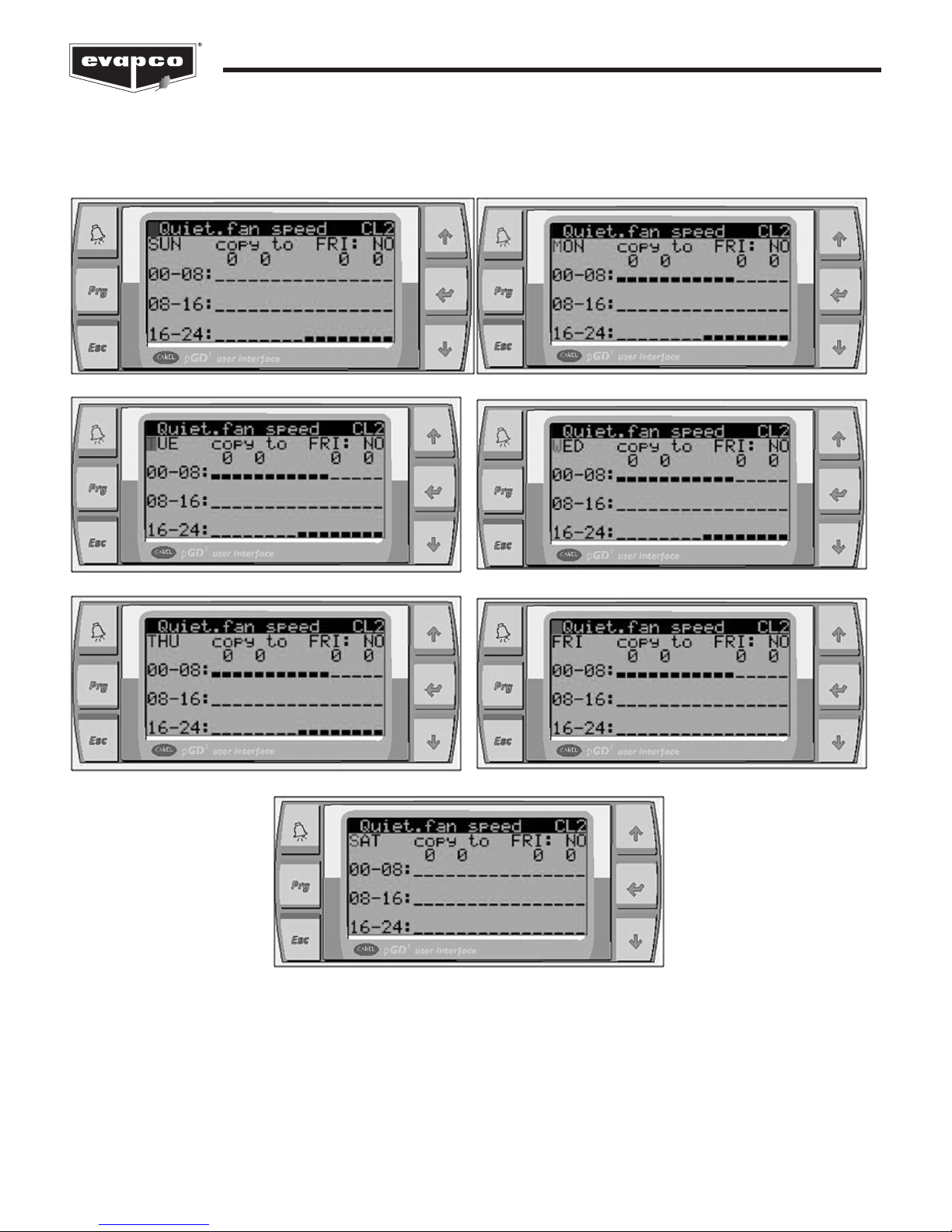
Repeat the steps above until the desired scheduled is set. Below is what the schedule of each day of the week should be for this
example.
The Quiet Mode weekly schedule for the presented example.
Figure 16
12
Controller User Manual
Operator Interface Screens
Welcome Screen
When the EVAPCO Controller is first energized, the system will do a self-diagnostic test and load all of the interface screens. When
the EVAPCO logo (Figure 17) appears, loading is complete. Press the ESC button to proceed to the Standby Status Screens.
Figure 17
The EVAPCO Controller Welcome Screen.
Standby Status Screens
The Standby Status Screens provide real time status of the various components of the eco-Air unit such as solenoid valves and
fans as well as live data of parameters such as sensor probe values, setpoints, and timer values. Note that all values shown on the
Standby Status Screens are read only. To view additional status screens, use the UP or DOWN buttons located on the operator
interface.
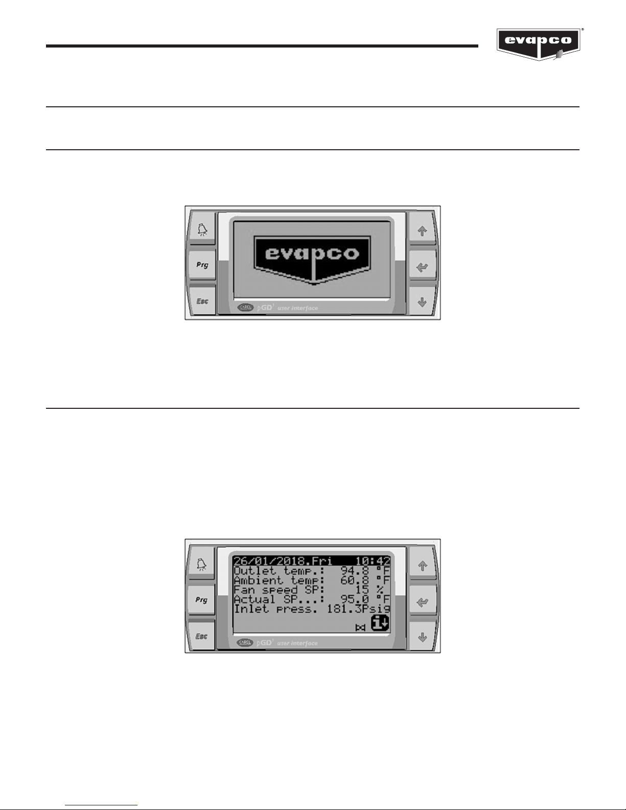
The Standby Screen shown in Figure 18 displays the process temperature, ambient temperature, command fan speed, active
setpoint, and the process pressure. Note that the process pressure is only shown if the eco-Air unit is a condenser. Also, if the ecoAir unit is a condenser, the process or Outlet Temperature will be a temperature derived from the temperature versus pressure
relationship of the refrigerant (see the Service Screens section for more information).
If the eco-Air unit is equipped with a pre-cooling system, the status of the solenoid valve is shown at the bottom of the screen as
shown in Figure 18.
Figure 18
The Standby Screen.
13
Controller User Manual
Image Description
Pre-cooling system is inactive (solenoid valve is closed).
Pre-cooling system is active (solenoid valve is open).
Table 2
The states of the pre-cooling system status indicator.
A bell icon in the lower right corner of the standby screen (see Figure 19) indicates that there is an active alarm. Press the ALARM
button to go directly to the Alarms Screen.
Figure 19
Standby Screen with an active alarm.
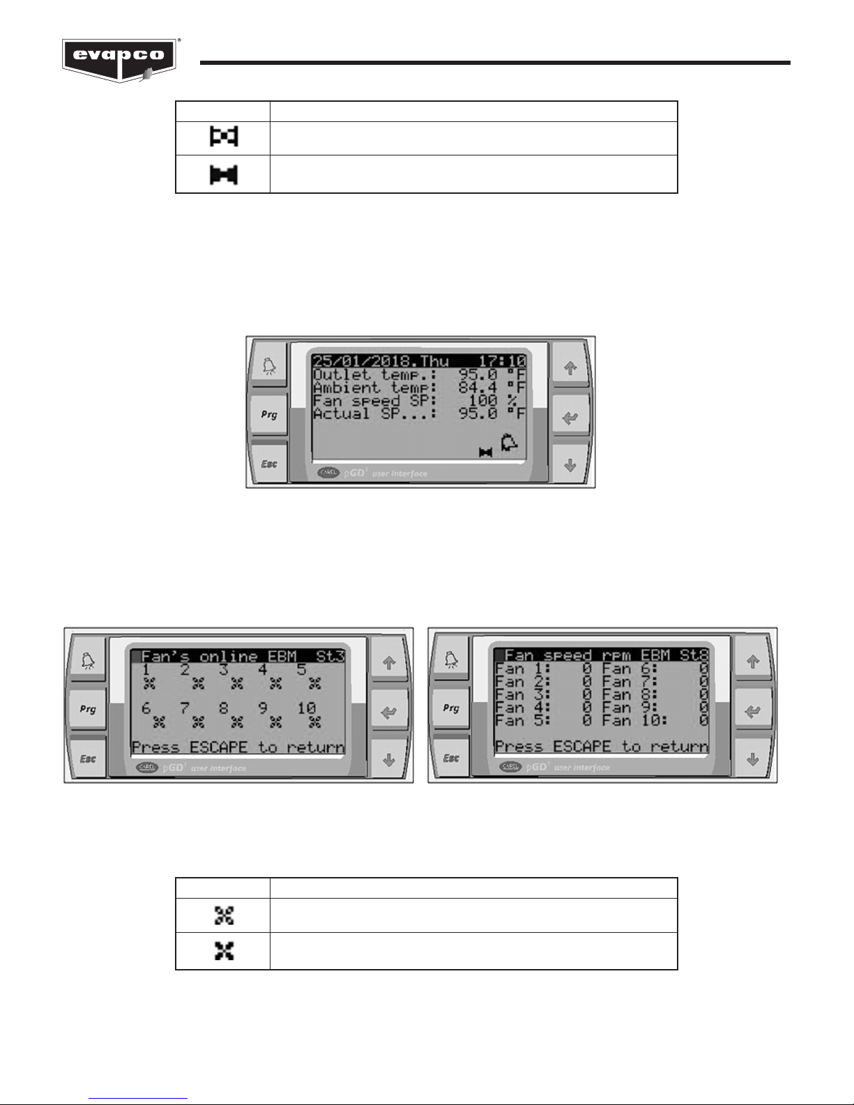
When the eco-Air unit is equipped with EC fan motors, the status and current speed of the fan motors may be viewed by pressing
the DOWN button.
Figure 20
The left screen displays the status of the fan motors. The right screen displays the live fan motor speeds in rpm.
Image Description
EC fan motor is off or is not communicating with the controller.
EC fan motor is online and communicating with the controller.
Table 3
The states of the EC fan motor status indicator.
14
 Loading...