

Page 1

EPower™ Controller
User Guide
EPower™ Power management and control units
Versions 3.06 and later
HA179769 Issue 11
December 2015
Page 2
Page 3

EPOWER CONTROLLER USER GUIDE
INSTALLATION AND OPERATION MANUAL
LIST OF SECTIONS
1 INTRODUCTION . . . . . . . . . . . . . . . . . . . . . . . . . . . . . . . . . . . . . . . . . . . . . . . . . . . . . . . . 13
2 INSTALLATION . . . . . . . . . . . . . . . . . . . . . . . . . . . . . . . . . . . . . . . . . . . . . . . . . . . . . . . . . . 14
3 OPERATOR INTERFACE . . . . . . . . . . . . . . . . . . . . . . . . . . . . . . . . . . . . . . . . . . . . . . . . . . 45
4 QUICKSTART . . . . . . . . . . . . . . . . . . . . . . . . . . . . . . . . . . . . . . . . . . . . . . . . . . . . . . . . . . . 45
5 OPERATOR MENU . . . . . . . . . . . . . . . . . . . . . . . . . . . . . . . . . . . . . . . . . . . . . . . . . . . . . . . 52
6 ENGINEER AND CONFIGURATION LEVEL MENUS . . . . . . . . . . . . . . . . . . . . . . . . . . . 55
7 USING ITOOLS . . . . . . . . . . . . . . . . . . . . . . . . . . . . . . . . . . . . . . . . . . . . . . . . . . . . . . . . . . 123
8 PARAMETER ADDRESSES (MODBUS) . . . . . . . . . . . . . . . . . . . . . . . . . . . . . . . . . . . . . . 151
9 PREDICTIVE LOAD MANAGEMENT OPTION . . . . . . . . . . . . . . . . . . . . . . . . . . . . . . . . 186
10 ALARMS . . . . . . . . . . . . . . . . . . . . . . . . . . . . . . . . . . . . . . . . . . . . . . . . . . . . . . . . . . . . . . . 211
11 TECHNICAL SPECIFICATION . . . . . . . . . . . . . . . . . . . . . . . . . . . . . . . . . . . . . . . . . . . . 214
12 MAINTENANCE . . . . . . . . . . . . . . . . . . . . . . . . . . . . . . . . . . . . . . . . . . . . . . . . . . . . . . . . 220
APPENDIX A REMOTE DISPLAY UNIT . . . . . . . . . . . . . . . . . . . . . . . . . . . . . . . . . . . . . . . . 223
APPENDIX B THREE PHASE FEEDBACK . . . . . . . . . . . . . . . . . . . . . . . . . . . . . . . . . . . . . . 249
INDEX . . . . . . . . . . . . . . . . . . . . . . . . . . . . . . . . . . . . . . . . . . . . . . . . . . . . . . . . . . . . . . . . . . . . 255
Associated Documents
HA179770 Communications Manual
HA028838 iTools help manual
Software Effectivity
This manual relates to units with software version 3.05
Patents
This product is covered by one or the more of the following patents:
France: FR 06/02582 (Published 2899038)
Europe: 07104780.7 (Pending)
US: 11/726,906 (Pending)
China: 200710089399.5 (Pending)
HA179769 Contents
Issue 11 Dec 15 Page i
Page 4

EPOWER CONTROLLER USER GUIDE
TABLE OF CONTENTS
Section Page
List of Sections . . . . . . . . . . . . . . . . . . . . . . . . . . . . . . . . . . . . . . . . . . . . . . . . . . . . . . . . . . . . . i
ASSOCIATED DOCUMENTS . . . . . . . . . . . . . . . . . . . . . . . . . . . . . . . . . . . . . . . . . . . . . . . . . i
SOFTWARE EFFECTIVITY . . . . . . . . . . . . . . . . . . . . . . . . . . . . . . . . . . . . . . . . . . . . . . . . . . . i
USER GUIDE . . . . . . . . . . . . . . . . . . . . . . . . . . . . . . . . . . . . . . . . . . . . . . . . . . . . . . . . . . . . . . . 13
1 INTRODUCTION . . . . . . . . . . . . . . . . . . . . . . . . . . . . . . . . . . . . . . . . . . . . . . . . . . . . . . . . 13
1.1 UNPACKING THE UNITS . . . . . . . . . . . . . . . . . . . . . . . . . . . . . . . . . . . . . . . . . . . . . . . . 13
2 INSTALLATION . . . . . . . . . . . . . . . . . . . . . . . . . . . . . . . . . . . . . . . . . . . . . . . . . . . . . . . . . 14
2.1 MECHANICAL INSTALLATION . . . . . . . . . . . . . . . . . . . . . . . . . . . . . . . . . . . . . . . . . . . 14
2.1.1 Fixing details . . . . . . . . . . . . . . . . . . . . . . . . . . . . . . . . . . . . . . . . . . . . . . . . . . . . . 14
GENERAL . . . . . . . . . . . . . . . . . . . . . . . . . . . . . . . . . . . . . . . . . . . . . . . . . . . . . . . . . . . 14
2.2 ELECTRICAL INSTALLATION . . . . . . . . . . . . . . . . . . . . . . . . . . . . . . . . . . . . . . . . . . . . 20
2.2.1 Driver Module . . . . . . . . . . . . . . . . . . . . . . . . . . . . . . . . . . . . . . . . . . . . . . . . . . . . 20
SUPPLY VOLTAGE . . . . . . . . . . . . . . . . . . . . . . . . . . . . . . . . . . . . . . . . . . . . . . . . . . . 20
FAN SUPPLIES . . . . . . . . . . . . . . . . . . . . . . . . . . . . . . . . . . . . . . . . . . . . . . . . . . . . . . . 20
ENABLE INPUT . . . . . . . . . . . . . . . . . . . . . . . . . . . . . . . . . . . . . . . . . . . . . . . . . . . . . . 20
SAFETY EARTH . . . . . . . . . . . . . . . . . . . . . . . . . . . . . . . . . . . . . . . . . . . . . . . . . . . . . . 21
SIGNAL WIRING . . . . . . . . . . . . . . . . . . . . . . . . . . . . . . . . . . . . . . . . . . . . . . . . . . . . . 22
WATCHDOG RELAY . . . . . . . . . . . . . . . . . . . . . . . . . . . . . . . . . . . . . . . . . . . . . . . . . 24
RELAY 1 . . . . . . . . . . . . . . . . . . . . . . . . . . . . . . . . . . . . . . . . . . . . . . . . . . . . . . . . . . . . 24
PREDICTIVE LOAD MANAGEMENT OPTION CONNECTOR . . . . . . . . . . . . . . . 25
CONFIGURATION PORT . . . . . . . . . . . . . . . . . . . . . . . . . . . . . . . . . . . . . . . . . . . . . . 26
COMMUNICATIONS PINOUTS . . . . . . . . . . . . . . . . . . . . . . . . . . . . . . . . . . . . . . . . 27
2.2.2 Power modules . . . . . . . . . . . . . . . . . . . . . . . . . . . . . . . . . . . . . . . . . . . . . . . . . . . . 30
LINE/LOAD CABLES . . . . . . . . . . . . . . . . . . . . . . . . . . . . . . . . . . . . . . . . . . . . . . . . . . 30
RIBBON CABLE . . . . . . . . . . . . . . . . . . . . . . . . . . . . . . . . . . . . . . . . . . . . . . . . . . . . . . 30
EXTERNAL CURRENT FEEDBACK . . . . . . . . . . . . . . . . . . . . . . . . . . . . . . . . . . . . . . 30
REMOTE VOLTAGE INPUT . . . . . . . . . . . . . . . . . . . . . . . . . . . . . . . . . . . . . . . . . . . . 31
NEUTRAL/PHASE REFERENCE INPUT . . . . . . . . . . . . . . . . . . . . . . . . . . . . . . . . . . . 31
ACCESS TO LINE AND LOAD TERMINATIONS . . . . . . . . . . . . . . . . . . . . . . . . . . . 32
THREE-PHASE STAR CONFIGURATIONS . . . . . . . . . . . . . . . . . . . . . . . . . . . . . . . 37
THREE-PHASE DELTA CONFIGURATIONS . . . . . . . . . . . . . . . . . . . . . . . . . . . . . . 38
TWO-LEG CONFIGURATIONS . . . . . . . . . . . . . . . . . . . . . . . . . . . . . . . . . . . . . . . . . 39
THREE PHASE CONFIGURATIONS WITH EXTERNAL FEEDBACK . . . . . . . . . . 40
3 OPERATOR INTERFACE . . . . . . . . . . . . . . . . . . . . . . . . . . . . . . . . . . . . . . . . . . . . . . . . . . 42
3.1 DISPLAY . . . . . . . . . . . . . . . . . . . . . . . . . . . . . . . . . . . . . . . . . . . . . . . . . . . . . . . . . . . . . . 42
3.2 PUSHBUTTONS . . . . . . . . . . . . . . . . . . . . . . . . . . . . . . . . . . . . . . . . . . . . . . . . . . . . . . . . 42
3.2.1 Configuration . . . . . . . . . . . . . . . . . . . . . . . . . . . . . . . . . . . . . . . . . . . . . . . . . . . . . 42
3.2.2 Operation . . . . . . . . . . . . . . . . . . . . . . . . . . . . . . . . . . . . . . . . . . . . . . . . . . . . . . . . 42
3.2.3 Menu item value selection . . . . . . . . . . . . . . . . . . . . . . . . . . . . . . . . . . . . . . . . . . 42
3.3 BEACONS . . . . . . . . . . . . . . . . . . . . . . . . . . . . . . . . . . . . . . . . . . . . . . . . . . . . . . . . . . . . . 43
3.4 FRONT PANEL MESSAGES . . . . . . . . . . . . . . . . . . . . . . . . . . . . . . . . . . . . . . . . . . . . . . 43
3.4.1 Instrument events . . . . . . . . . . . . . . . . . . . . . . . . . . . . . . . . . . . . . . . . . . . . . . . . . . 43
3.4.2 Indication alarms . . . . . . . . . . . . . . . . . . . . . . . . . . . . . . . . . . . . . . . . . . . . . . . . . . 43
3.4.3 System alarms . . . . . . . . . . . . . . . . . . . . . . . . . . . . . . . . . . . . . . . . . . . . . . . . . . . . . 43
3.4.4 Process alarms . . . . . . . . . . . . . . . . . . . . . . . . . . . . . . . . . . . . . . . . . . . . . . . . . . . . 43
3.4.5 Configuration errors . . . . . . . . . . . . . . . . . . . . . . . . . . . . . . . . . . . . . . . . . . . . . . . 44
3.4.6 Standby errors . . . . . . . . . . . . . . . . . . . . . . . . . . . . . . . . . . . . . . . . . . . . . . . . . . . . 44
Contents HA179769
Page ii Issue 11 Dec 15
Page 5

EPOWER CONTROLLER USER GUIDE
TABLE OF CONTENTS (CONT.)
Section Page
3.4.7 Power module errors . . . . . . . . . . . . . . . . . . . . . . . . . . . . . . . . . . . . . . . . . . . . . . . 44
3.4.8 General errors . . . . . . . . . . . . . . . . . . . . . . . . . . . . . . . . . . . . . . . . . . . . . . . . . . . . . 44
3.4.9 Reset errors . . . . . . . . . . . . . . . . . . . . . . . . . . . . . . . . . . . . . . . . . . . . . . . . . . . . . . . 44
3.4.10 Fatal errors . . . . . . . . . . . . . . . . . . . . . . . . . . . . . . . . . . . . . . . . . . . . . . . . . . . . . . 44
4 QUICKSTART . . . . . . . . . . . . . . . . . . . . . . . . . . . . . . . . . . . . . . . . . . . . . . . . . . . . . . . . . . . 45
4.1 QUICKSTART MENU PARAMETERS . . . . . . . . . . . . . . . . . . . . . . . . . . . . . . . . . . . . . . . 46
4.2 SOME DEFINITIONS . . . . . . . . . . . . . . . . . . . . . . . . . . . . . . . . . . . . . . . . . . . . . . . . . . . 48
4.2.1 Firing modes . . . . . . . . . . . . . . . . . . . . . . . . . . . . . . . . . . . . . . . . . . . . . . . . . . . . . 48
LOGIC . . . . . . . . . . . . . . . . . . . . . . . . . . . . . . . . . . . . . . . . . . . . . . . . . . . . . . . . . . . . . . 48
BURST FIXED FIRING . . . . . . . . . . . . . . . . . . . . . . . . . . . . . . . . . . . . . . . . . . . . . . . . . 48
BURST VARIABLE FIRING . . . . . . . . . . . . . . . . . . . . . . . . . . . . . . . . . . . . . . . . . . . . . 49
PHASE ANGLE CONTROL . . . . . . . . . . . . . . . . . . . . . . . . . . . . . . . . . . . . . . . . . . . . . 49
HALF CYCLE MODE . . . . . . . . . . . . . . . . . . . . . . . . . . . . . . . . . . . . . . . . . . . . . . . . . . 49
4.2.2 Feedback type . . . . . . . . . . . . . . . . . . . . . . . . . . . . . . . . . . . . . . . . . . . . . . . . . . . . 50
4.2.3 Transfer Mode . . . . . . . . . . . . . . . . . . . . . . . . . . . . . . . . . . . . . . . . . . . . . . . . . . . . 51
4.2.4 Limitation features . . . . . . . . . . . . . . . . . . . . . . . . . . . . . . . . . . . . . . . . . . . . . . . . . 51
FIRING ANGLE LIMITING . . . . . . . . . . . . . . . . . . . . . . . . . . . . . . . . . . . . . . . . . . . . . . 51
DUTY CYCLE LIMITING . . . . . . . . . . . . . . . . . . . . . . . . . . . . . . . . . . . . . . . . . . . . . . . 51
5 OPERATOR MENU . . . . . . . . . . . . . . . . . . . . . . . . . . . . . . . . . . . . . . . . . . . . . . . . . . . . . . 52
5.1 SUMMARY PAGES . . . . . . . . . . . . . . . . . . . . . . . . . . . . . . . . . . . . . . . . . . . . . . . . . . . . . 52
5.1.1 Single phase summary page . . . . . . . . . . . . . . . . . . . . . . . . . . . . . . . . . . . . . . . . 52
5.1.2 Two or three phase summary page . . . . . . . . . . . . . . . . . . . . . . . . . . . . . . . . . . 52
5.1.3 Two by two phase summary page . . . . . . . . . . . . . . . . . . . . . . . . . . . . . . . . . . . 52
5.2 TOP LEVEL OPERATOR (USER) MENU . . . . . . . . . . . . . . . . . . . . . . . . . . . . . . . . . . . . . 53
5.2.1 Alarm Summary pages . . . . . . . . . . . . . . . . . . . . . . . . . . . . . . . . . . . . . . . . . . . . . 53
5.2.2 Event Log . . . . . . . . . . . . . . . . . . . . . . . . . . . . . . . . . . . . . . . . . . . . . . . . . . . . . . . . 53
5.2.3 Strategy Standby mode . . . . . . . . . . . . . . . . . . . . . . . . . . . . . . . . . . . . . . . . . . . . 54
6 ENGINEER AND CONFIGURATION LEVEL MENUS . . . . . . . . . . . . . . . . . . . . . . . . . . 55
6.1 ACCESS TO THE ENGINEER AND CONFIGURATION MENUS . . . . . . . . . . . . . . . . 55
6.1.1 Engineer level menu . . . . . . . . . . . . . . . . . . . . . . . . . . . . . . . . . . . . . . . . . . . . . . 55
6.1.2 Configuration level menu . . . . . . . . . . . . . . . . . . . . . . . . . . . . . . . . . . . . . . . . . . 56
6.2 TOP LEVEL MENU . . . . . . . . . . . . . . . . . . . . . . . . . . . . . . . . . . . . . . . . . . . . . . . . . . . . . . 57
6.3 ACCESS MENU . . . . . . . . . . . . . . . . . . . . . . . . . . . . . . . . . . . . . . . . . . . . . . . . . . . . . . . . 58
6.3.1 Engineer level menu . . . . . . . . . . . . . . . . . . . . . . . . . . . . . . . . . . . . . . . . . . . . . . . 58
6.3.2 Configuration level access menu . . . . . . . . . . . . . . . . . . . . . . . . . . . . . . . . . . . . 59
GOTO MENU . . . . . . . . . . . . . . . . . . . . . . . . . . . . . . . . . . . . . . . . . . . . . . . . . . . . . . . 59
PASS CODE EDITING . . . . . . . . . . . . . . . . . . . . . . . . . . . . . . . . . . . . . . . . . . . . . . . . 60
6.4 ANALOGIP MENU . . . . . . . . . . . . . . . . . . . . . . . . . . . . . . . . . . . . . . . . . . . . . . . . . . . . . 61
6.4.1 Analogue input parameters . . . . . . . . . . . . . . . . . . . . . . . . . . . . . . . . . . . . . . . . 61
6.5 ANALOGOP MENU . . . . . . . . . . . . . . . . . . . . . . . . . . . . . . . . . . . . . . . . . . . . . . . . . . . . 62
6.5.1 Analogue output ‘Main’ submenu parameters . . . . . . . . . . . . . . . . . . . . . . . . . 62
6.5.2 Analogue output ‘Alm’ parameters . . . . . . . . . . . . . . . . . . . . . . . . . . . . . . . . . . 63
6.6 COMMS MENU . . . . . . . . . . . . . . . . . . . . . . . . . . . . . . . . . . . . . . . . . . . . . . . . . . . . . . . . 64
6.6.1 Communications User menu parameters . . . . . . . . . . . . . . . . . . . . . . . . . . . . . 65
6.6.2 COMMS REMOTE PANEL PARAMETERS . . . . . . . . . . . . . . . . . . . . . . . . . . . . . 66
6.7 CONTROL MENU . . . . . . . . . . . . . . . . . . . . . . . . . . . . . . . . . . . . . . . . . . . . . . . . . . . . . . 67
6.7.1 Control Setup Parameters . . . . . . . . . . . . . . . . . . . . . . . . . . . . . . . . . . . . . . . . . . 68
HA179769 Contents
Issue 11 Dec 15 Page iii
Page 6

EPOWER CONTROLLER USER GUIDE
TABLE OF CONTENTS (CONT.)
Section Page
6.7.2 Control Main Parameters . . . . . . . . . . . . . . . . . . . . . . . . . . . . . . . . . . . . . . . . . . . 69
6.7.3 Control Limit parameters . . . . . . . . . . . . . . . . . . . . . . . . . . . . . . . . . . . . . . . . . . . 70
6.7.4 Control Diag parameters . . . . . . . . . . . . . . . . . . . . . . . . . . . . . . . . . . . . . . . . . . . 71
6.7.5 Control Alarm disable parameters . . . . . . . . . . . . . . . . . . . . . . . . . . . . . . . . . . . 72
6.7.6 Control Alarm detection parameters . . . . . . . . . . . . . . . . . . . . . . . . . . . . . . . . . 73
6.7.7 Control Alarm signalling parameters . . . . . . . . . . . . . . . . . . . . . . . . . . . . . . . . . 74
6.7.8 Control Alarm Latch parameters . . . . . . . . . . . . . . . . . . . . . . . . . . . . . . . . . . . . 75
6.7.9 Control Alarm Acknowledgement parameters . . . . . . . . . . . . . . . . . . . . . . . . 76
6.7.10 Control Alarm Stop parameters . . . . . . . . . . . . . . . . . . . . . . . . . . . . . . . . . . . . 77
6.8 COUNTER MENU . . . . . . . . . . . . . . . . . . . . . . . . . . . . . . . . . . . . . . . . . . . . . . . . . . . . . . 78
6.8.1 Counter configuration menu . . . . . . . . . . . . . . . . . . . . . . . . . . . . . . . . . . . . . . . . 78
6.8.2 Cascading counters . . . . . . . . . . . . . . . . . . . . . . . . . . . . . . . . . . . . . . . . . . . . . . . 79
6.9 DIGITAL I/O MENU . . . . . . . . . . . . . . . . . . . . . . . . . . . . . . . . . . . . . . . . . . . . . . . . . . . . . 80
6.10 ENERGY . . . . . . . . . . . . . . . . . . . . . . . . . . . . . . . . . . . . . . . . . . . . . . . . . . . . . . . . . . . . . 81
6.10.1 Energy counter parameters . . . . . . . . . . . . . . . . . . . . . . . . . . . . . . . . . . . . . . . 82
6.10.2 Resolution . . . . . . . . . . . . . . . . . . . . . . . . . . . . . . . . . . . . . . . . . . . . . . . . . . . . . . . 83
6.11 EVENT LOG MENU . . . . . . . . . . . . . . . . . . . . . . . . . . . . . . . . . . . . . . . . . . . . . . . . . . . . 83
6.12 FAULT DETECTION MENU . . . . . . . . . . . . . . . . . . . . . . . . . . . . . . . . . . . . . . . . . . . . . 84
6.13 FIRING OUTPUT MENU . . . . . . . . . . . . . . . . . . . . . . . . . . . . . . . . . . . . . . . . . . . . . . . . 85
6.14 INSTRUMENT MENU . . . . . . . . . . . . . . . . . . . . . . . . . . . . . . . . . . . . . . . . . . . . . . . . . . 87
6.14.1 Instrument Display parameters . . . . . . . . . . . . . . . . . . . . . . . . . . . . . . . . . . . . . 87
6.14.2 Instrument Config parameters . . . . . . . . . . . . . . . . . . . . . . . . . . . . . . . . . . . . . 88
6.15 IP MONITOR MENU . . . . . . . . . . . . . . . . . . . . . . . . . . . . . . . . . . . . . . . . . . . . . . . . . . . 89
6.16 LGC2 (TWO INPUT LOGIC OPERATOR) MENU . . . . . . . . . . . . . . . . . . . . . . . . . . . 91
6.16.1 Lgc2 Parameters . . . . . . . . . . . . . . . . . . . . . . . . . . . . . . . . . . . . . . . . . . . . . . . . . 91
6.17 LGC8 (EIGHT-INPUT LOGIC OPERATOR) MENU . . . . . . . . . . . . . . . . . . . . . . . . . . 93
6.18 MATH2 MENU . . . . . . . . . . . . . . . . . . . . . . . . . . . . . . . . . . . . . . . . . . . . . . . . . . . . . . . . 94
6.19 MODULATOR MENU . . . . . . . . . . . . . . . . . . . . . . . . . . . . . . . . . . . . . . . . . . . . . . . . . . 96
6.20 NETWORK MENU . . . . . . . . . . . . . . . . . . . . . . . . . . . . . . . . . . . . . . . . . . . . . . . . . . . . 97
6.20.1 Meas submenu . . . . . . . . . . . . . . . . . . . . . . . . . . . . . . . . . . . . . . . . . . . . . . . . . . 98
6.20.2 Network Setup Submenu . . . . . . . . . . . . . . . . . . . . . . . . . . . . . . . . . . . . . . . . . 100
PARTIAL LOAD FAILURE CALCULATIONS . . . . . . . . . . . . . . . . . . . . . . . . . . . . . . . 102
6.20.3 Network alarms . . . . . . . . . . . . . . . . . . . . . . . . . . . . . . . . . . . . . . . . . . . . . . . . . . 103
NETWORK ALMDIS SUBMENU . . . . . . . . . . . . . . . . . . . . . . . . . . . . . . . . . . . . . . . . 103
NETWORK ALMDET SUBMENU . . . . . . . . . . . . . . . . . . . . . . . . . . . . . . . . . . . . . . . 104
NETWORK ALMSIG SUBMENU . . . . . . . . . . . . . . . . . . . . . . . . . . . . . . . . . . . . . . . . 104
NETWORK ALMLAT SUBMENU . . . . . . . . . . . . . . . . . . . . . . . . . . . . . . . . . . . . . . . . 104
NETWORK ALMACK SUBMENU . . . . . . . . . . . . . . . . . . . . . . . . . . . . . . . . . . . . . . . 104
NETWORK ALMSTOP SUBMENU . . . . . . . . . . . . . . . . . . . . . . . . . . . . . . . . . . . . . . 104
6.21 PLM (STATION AND NETWORK LM PARAMETERS) MENU . . . . . . . . . . . . . . . . . 105
6.21.1 Main . . . . . . . . . . . . . . . . . . . . . . . . . . . . . . . . . . . . . . . . . . . . . . . . . . . . . . . . . . . . 105
6.21.2 Predictive Load management ‘Station’ menu . . . . . . . . . . . . . . . . . . . . . . . . 107
6.21.3 Predictive Load Management ‘Network’ menu . . . . . . . . . . . . . . . . . . . . . . . 108
6.21.4 Predictive Load Management ‘Alarm’ menus . . . . . . . . . . . . . . . . . . . . . . . . 109
6.22 PLMCHAN (LOAD MANAGEMENT OPTION INTERFACE) MENU . . . . . . . . . . . . 110
6.23 LOAD TAP CHANGER (LTC) OPTION . . . . . . . . . . . . . . . . . . . . . . . . . . . . . . . . . . . . 111
6.23.1 MainPrm parameters . . . . . . . . . . . . . . . . . . . . . . . . . . . . . . . . . . . . . . . . . . . . . 112
Contents HA179769
Page iv Issue 11 Dec 15
Page 7

EPOWER CONTROLLER USER GUIDE
TABLE OF CONTENTS (CONT.)
Section Page
6.23.2 LTC Alarm . . . . . . . . . . . . . . . . . . . . . . . . . . . . . . . . . . . . . . . . . . . . . . . . . . . . . . . 112
PARAMETERS . . . . . . . . . . . . . . . . . . . . . . . . . . . . . . . . . . . . . . . . . . . . . . . . . . . . . . . 112
6.23.3 LTC Application wiring . . . . . . . . . . . . . . . . . . . . . . . . . . . . . . . . . . . . . . . . . . . . 113
6.24 RELAY MENU . . . . . . . . . . . . . . . . . . . . . . . . . . . . . . . . . . . . . . . . . . . . . . . . . . . . . . . . . 116
6.24.1 Relay parameters . . . . . . . . . . . . . . . . . . . . . . . . . . . . . . . . . . . . . . . . . . . . . . . . 116
6.25 SETPROV MENU . . . . . . . . . . . . . . . . . . . . . . . . . . . . . . . . . . . . . . . . . . . . . . . . . . . . . . 117
6.25.1 Setpoint provider parameters . . . . . . . . . . . . . . . . . . . . . . . . . . . . . . . . . . . . . . 118
6.26 TIMER MENU . . . . . . . . . . . . . . . . . . . . . . . . . . . . . . . . . . . . . . . . . . . . . . . . . . . . . . . . . 119
6.26.1 Timer configuration . . . . . . . . . . . . . . . . . . . . . . . . . . . . . . . . . . . . . . . . . . . . . . 119
6.26.2 Timer examples . . . . . . . . . . . . . . . . . . . . . . . . . . . . . . . . . . . . . . . . . . . . . . . . . . 120
6.27 TOTALISER MENU . . . . . . . . . . . . . . . . . . . . . . . . . . . . . . . . . . . . . . . . . . . . . . . . . . . . 121
6.28 USER VALUE MENU . . . . . . . . . . . . . . . . . . . . . . . . . . . . . . . . . . . . . . . . . . . . . . . . . . . 122
7 USING ITOOLS . . . . . . . . . . . . . . . . . . . . . . . . . . . . . . . . . . . . . . . . . . . . . . . . . . . . . . . . . . 123
7.1 iTools CONNECTION . . . . . . . . . . . . . . . . . . . . . . . . . . . . . . . . . . . . . . . . . . . . . . . . . . 123
7.1.1 Serial communications . . . . . . . . . . . . . . . . . . . . . . . . . . . . . . . . . . . . . . . . . . . . . 123
7.1.2 Ethernet (Modbus TCP) communications . . . . . . . . . . . . . . . . . . . . . . . . . . . . . 124
7.1.3 Direct Connection . . . . . . . . . . . . . . . . . . . . . . . . . . . . . . . . . . . . . . . . . . . . . . . . . 126
WIRING . . . . . . . . . . . . . . . . . . . . . . . . . . . . . . . . . . . . . . . . . . . . . . . . . . . . . . . . . . . . 126
7.2 SCANNING FOR INSTRUMENTS . . . . . . . . . . . . . . . . . . . . . . . . . . . . . . . . . . . . . . . . . 127
7.3 GRAPHICAL WIRING EDITOR . . . . . . . . . . . . . . . . . . . . . . . . . . . . . . . . . . . . . . . . . . . . 128
7.3.1 Toolbar . . . . . . . . . . . . . . . . . . . . . . . . . . . . . . . . . . . . . . . . . . . . . . . . . . . . . . . . . . 129
7.3.2 Wiring editor operating details . . . . . . . . . . . . . . . . . . . . . . . . . . . . . . . . . . . . . . 129
COMPONENT SELECTION . . . . . . . . . . . . . . . . . . . . . . . . . . . . . . . . . . . . . . . . . . . 129
BLOCK EXECUTION ORDER . . . . . . . . . . . . . . . . . . . . . . . . . . . . . . . . . . . . . . . . . . 129
FUNCTION BLOCKS . . . . . . . . . . . . . . . . . . . . . . . . . . . . . . . . . . . . . . . . . . . . . . . . . 130
WIRES . . . . . . . . . . . . . . . . . . . . . . . . . . . . . . . . . . . . . . . . . . . . . . . . . . . . . . . . . . . . . . 132
THICK WIRES . . . . . . . . . . . . . . . . . . . . . . . . . . . . . . . . . . . . . . . . . . . . . . . . . . . . . . . 133
COMMENTS . . . . . . . . . . . . . . . . . . . . . . . . . . . . . . . . . . . . . . . . . . . . . . . . . . . . . . . . 133
MONITORS . . . . . . . . . . . . . . . . . . . . . . . . . . . . . . . . . . . . . . . . . . . . . . . . . . . . . . . . . 134
DOWNLOADING . . . . . . . . . . . . . . . . . . . . . . . . . . . . . . . . . . . . . . . . . . . . . . . . . . . . 134
COLOURS . . . . . . . . . . . . . . . . . . . . . . . . . . . . . . . . . . . . . . . . . . . . . . . . . . . . . . . . . . 135
DIAGRAM CONTEXT MENU . . . . . . . . . . . . . . . . . . . . . . . . . . . . . . . . . . . . . . . . . . 135
COMPOUNDS . . . . . . . . . . . . . . . . . . . . . . . . . . . . . . . . . . . . . . . . . . . . . . . . . . . . . . 136
TOOL TIPS . . . . . . . . . . . . . . . . . . . . . . . . . . . . . . . . . . . . . . . . . . . . . . . . . . . . . . . . . . 137
7.4 PARAMETER EXPLORER . . . . . . . . . . . . . . . . . . . . . . . . . . . . . . . . . . . . . . . . . . . . . . . . 138
7.4.1 Parameter explorer detail . . . . . . . . . . . . . . . . . . . . . . . . . . . . . . . . . . . . . . . . . . 139
7.4.2 Explorer tools . . . . . . . . . . . . . . . . . . . . . . . . . . . . . . . . . . . . . . . . . . . . . . . . . . . . . 140
7.5 FIELDBUS GATEWAY . . . . . . . . . . . . . . . . . . . . . . . . . . . . . . . . . . . . . . . . . . . . . . . . . . . 141
EE CHECKSUM FAIL ERROR . . . . . . . . . . . . . . . . . . . . . . . . . . . . . . . . . . . . . . . . . . 142
7.6 DEVICE PANEL . . . . . . . . . . . . . . . . . . . . . . . . . . . . . . . . . . . . . . . . . . . . . . . . . . . . . . . . 145
7.7 WATCH/RECIPE EDITOR . . . . . . . . . . . . . . . . . . . . . . . . . . . . . . . . . . . . . . . . . . . . . . . . 146
7.7.1 Creating a Watch List . . . . . . . . . . . . . . . . . . . . . . . . . . . . . . . . . . . . . . . . . . . . . . 146
ADDING PARAMETERS TO THE WATCH LIST . . . . . . . . . . . . . . . . . . . . . . . . . . . 146
DATA SET CREATION . . . . . . . . . . . . . . . . . . . . . . . . . . . . . . . . . . . . . . . . . . . . . . . . 146
7.7.2 Watch Recipe toolbar icons . . . . . . . . . . . . . . . . . . . . . . . . . . . . . . . . . . . . . . . . . 147
7.7.3 Watch/Recipe Context Menu . . . . . . . . . . . . . . . . . . . . . . . . . . . . . . . . . . . . . . . 147
7.8 USER PAGES . . . . . . . . . . . . . . . . . . . . . . . . . . . . . . . . . . . . . . . . . . . . . . . . . . . . . . . . . . 148
HA179769 Contents
Issue 11 Dec 15 Page v
Page 8

EPOWER CONTROLLER USER GUIDE
TABLE OF CONTENTS (CONT.)
Section Page
7.8.1 User Page creation . . . . . . . . . . . . . . . . . . . . . . . . . . . . . . . . . . . . . . . . . . . . . . . . 148
7.8.2 Style examples . . . . . . . . . . . . . . . . . . . . . . . . . . . . . . . . . . . . . . . . . . . . . . . . . . . . 149
7.8.3 User Pages Tools . . . . . . . . . . . . . . . . . . . . . . . . . . . . . . . . . . . . . . . . . . . . . . . . . . 150
8 PARAMETER ADDRESSES (MODBUS) . . . . . . . . . . . . . . . . . . . . . . . . . . . . . . . . . . . . . 151
8.1 INTRODUCTION . . . . . . . . . . . . . . . . . . . . . . . . . . . . . . . . . . . . . . . . . . . . . . . . . . . . . . . 151
8.2 PARAMETER TYPES . . . . . . . . . . . . . . . . . . . . . . . . . . . . . . . . . . . . . . . . . . . . . . . . . . . . 151
8.3 PARAMETER SCALING . . . . . . . . . . . . . . . . . . . . . . . . . . . . . . . . . . . . . . . . . . . . . . . . . 152
8.3.1 Conditional scaling . . . . . . . . . . . . . . . . . . . . . . . . . . . . . . . . . . . . . . . . . . . . . . . . 152
8.4 PARAMETER TABLE . . . . . . . . . . . . . . . . . . . . . . . . . . . . . . . . . . . . . . . . . . . . . . . . . . . . 153
9 PREDICTIVE LOAD MANAGEMENT OPTION . . . . . . . . . . . . . . . . . . . . . . . . . . . . . . . 186
9.1 GENERAL DESCRIPTION . . . . . . . . . . . . . . . . . . . . . . . . . . . . . . . . . . . . . . . . . . . . . . . . 186
9.1.1 Load Management layout . . . . . . . . . . . . . . . . . . . . . . . . . . . . . . . . . . . . . . . . . . 186
9.1.2 Power modulation and accuracy . . . . . . . . . . . . . . . . . . . . . . . . . . . . . . . . . . . . 187
9.2 LOAD SEQUENCING . . . . . . . . . . . . . . . . . . . . . . . . . . . . . . . . . . . . . . . . . . . . . . . . . . . 188
9.2.1 Incremental control type 1 . . . . . . . . . . . . . . . . . . . . . . . . . . . . . . . . . . . . . . . . . . 188
9.2.2 Incremental control type 2 . . . . . . . . . . . . . . . . . . . . . . . . . . . . . . . . . . . . . . . . . . 189
9.2.3 Rotating Incremental control . . . . . . . . . . . . . . . . . . . . . . . . . . . . . . . . . . . . . . . . 190
9.2.4 Distributed control . . . . . . . . . . . . . . . . . . . . . . . . . . . . . . . . . . . . . . . . . . . . . . . . 191
9.2.5 Incremental/Distributed control . . . . . . . . . . . . . . . . . . . . . . . . . . . . . . . . . . . . . 191
9.2.6 Rotating Incremental Distributed control . . . . . . . . . . . . . . . . . . . . . . . . . . . . . 192
9.3 LOAD SHARING . . . . . . . . . . . . . . . . . . . . . . . . . . . . . . . . . . . . . . . . . . . . . . . . . . . . . . . 193
9.3.1 Total power demand . . . . . . . . . . . . . . . . . . . . . . . . . . . . . . . . . . . . . . . . . . . . . . 193
9.3.2 Sharing Efficiency Factor (F) . . . . . . . . . . . . . . . . . . . . . . . . . . . . . . . . . . . . . . . . 193
9.3.3 Sharing algorithm . . . . . . . . . . . . . . . . . . . . . . . . . . . . . . . . . . . . . . . . . . . . . . . . . 194
9.4 LOAD SHEDDING . . . . . . . . . . . . . . . . . . . . . . . . . . . . . . . . . . . . . . . . . . . . . . . . . . . . . . 195
9.4.1 Definitions . . . . . . . . . . . . . . . . . . . . . . . . . . . . . . . . . . . . . . . . . . . . . . . . . . . . . . . 195
9.4.2 Reduction of power demand . . . . . . . . . . . . . . . . . . . . . . . . . . . . . . . . . . . . . . . 195
SHEDDING ABILITY FACTOR . . . . . . . . . . . . . . . . . . . . . . . . . . . . . . . . . . . . . . . . . 196
9.4.3 Load shedding comparisons . . . . . . . . . . . . . . . . . . . . . . . . . . . . . . . . . . . . . . . . 197
WITHOUT LOAD SHARING, SYNCHRONISED . . . . . . . . . . . . . . . . . . . . . . . . . . . 197
WITHOUT LOAD SHARING, SYNCHRONISED, REDUCTION FACTOR 50% . . 198
WITHOUT LOAD SHARING NOT SYNCHRONISED . . . . . . . . . . . . . . . . . . . . . . . 198
WITHOUT LOAD SHARING, NON-SYNCHRONISED, REDUCTION FACTOR 50% 199
WITH LOAD SHARING . . . . . . . . . . . . . . . . . . . . . . . . . . . . . . . . . . . . . . . . . . . . . . . 199
WITH LOAD SHARING, REDUCTION FACTOR = 50% . . . . . . . . . . . . . . . . . . . . 200
9.5 CONFIGURATION . . . . . . . . . . . . . . . . . . . . . . . . . . . . . . . . . . . . . . . . . . . . . . . . . . . . . 201
9.5.1 iTools Graphical wiring . . . . . . . . . . . . . . . . . . . . . . . . . . . . . . . . . . . . . . . . . . . . 201
STANDARD POWER CONTROL LOOP . . . . . . . . . . . . . . . . . . . . . . . . . . . . . . . . . 201
LOAD MANAGEMENT CHANNELS (LMCHAN 1 TO LMCHAN 4) . . . . . . . . . . . 201
GLOBAL LOAD MANAGEMENT CONTROL (LOADMNG) . . . . . . . . . . . . . . . . . 201
CALCULATION AND COMMUNICATIONS . . . . . . . . . . . . . . . . . . . . . . . . . . . . . . 201
9.5.2 Predictive Load Management function block details . . . . . . . . . . . . . . . . . . . 204
LM TYPE . . . . . . . . . . . . . . . . . . . . . . . . . . . . . . . . . . . . . . . . . . . . . . . . . . . . . . . . . . . . 204
PERIOD . . . . . . . . . . . . . . . . . . . . . . . . . . . . . . . . . . . . . . . . . . . . . . . . . . . . . . . . . . . . 204
ADDRESS . . . . . . . . . . . . . . . . . . . . . . . . . . . . . . . . . . . . . . . . . . . . . . . . . . . . . . . . . . 205
Ps . . . . . . . . . . . . . . . . . . . . . . . . . . . . . . . . . . . . . . . . . . . . . . . . . . . . . . . . . . . . . . . . . 205
SHEDFACTOR . . . . . . . . . . . . . . . . . . . . . . . . . . . . . . . . . . . . . . . . . . . . . . . . . . . . . . 205
Contents HA179769
Page vi Issue 11 Dec 15
Page 9

EPOWER CONTROLLER USER GUIDE
TABLE OF CONTENTS (CONT.)
Section Page
GROUP . . . . . . . . . . . . . . . . . . . . . . . . . . . . . . . . . . . . . . . . . . . . . . . . . . . . . . . . . . . . 206
PZMAX . . . . . . . . . . . . . . . . . . . . . . . . . . . . . . . . . . . . . . . . . . . . . . . . . . . . . . . . . . . . . 206
STATUS . . . . . . . . . . . . . . . . . . . . . . . . . . . . . . . . . . . . . . . . . . . . . . . . . . . . . . . . . . . . 206
NUMCHAN . . . . . . . . . . . . . . . . . . . . . . . . . . . . . . . . . . . . . . . . . . . . . . . . . . . . . . . . . 207
TOTALSTATION . . . . . . . . . . . . . . . . . . . . . . . . . . . . . . . . . . . . . . . . . . . . . . . . . . . . . 207
TOTALCHANNELS . . . . . . . . . . . . . . . . . . . . . . . . . . . . . . . . . . . . . . . . . . . . . . . . . . . 207
PMAX . . . . . . . . . . . . . . . . . . . . . . . . . . . . . . . . . . . . . . . . . . . . . . . . . . . . . . . . . . . . . . 208
PT . . . . . . . . . . . . . . . . . . . . . . . . . . . . . . . . . . . . . . . . . . . . . . . . . . . . . . . . . . . . . . . . . 208
PR . . . . . . . . . . . . . . . . . . . . . . . . . . . . . . . . . . . . . . . . . . . . . . . . . . . . . . . . . . . . . . . . . 208
EFFICIENCY . . . . . . . . . . . . . . . . . . . . . . . . . . . . . . . . . . . . . . . . . . . . . . . . . . . . . . . . 208
MASTER ADDRESS . . . . . . . . . . . . . . . . . . . . . . . . . . . . . . . . . . . . . . . . . . . . . . . . . . 209
9.6 MASTER ELECTION . . . . . . . . . . . . . . . . . . . . . . . . . . . . . . . . . . . . . . . . . . . . . . . . . . . . 209
9.6.1 Master Election triggers . . . . . . . . . . . . . . . . . . . . . . . . . . . . . . . . . . . . . . . . . . . . 209
9.7 ALARM INDICATION . . . . . . . . . . . . . . . . . . . . . . . . . . . . . . . . . . . . . . . . . . . . . . . . . . . 210
PROVERPS . . . . . . . . . . . . . . . . . . . . . . . . . . . . . . . . . . . . . . . . . . . . . . . . . . . . . . . . . . 210
9.8 TROUBLE SHOOTING . . . . . . . . . . . . . . . . . . . . . . . . . . . . . . . . . . . . . . . . . . . . . . . . . . 210
9.8.1 Wrong Station status . . . . . . . . . . . . . . . . . . . . . . . . . . . . . . . . . . . . . . . . . . . . . . 210
DUPLICATE LM ADDRESS . . . . . . . . . . . . . . . . . . . . . . . . . . . . . . . . . . . . . . . . . . . . 210
STATION STATUS PERMANENTLY ‘PENDING’ . . . . . . . . . . . . . . . . . . . . . . . . . . . 210
STATION TYPE MISMATCH . . . . . . . . . . . . . . . . . . . . . . . . . . . . . . . . . . . . . . . . . . . 210
10 ALARMS . . . . . . . . . . . . . . . . . . . . . . . . . . . . . . . . . . . . . . . . . . . . . . . . . . . . . . . . . . . . . . 211
10.1 SYSTEM ALARMS . . . . . . . . . . . . . . . . . . . . . . . . . . . . . . . . . . . . . . . . . . . . . . . . . . . . . 211
10.1.1 Missing mains . . . . . . . . . . . . . . . . . . . . . . . . . . . . . . . . . . . . . . . . . . . . . . . . . . . 211
10.1.2 Thyristor short circuit . . . . . . . . . . . . . . . . . . . . . . . . . . . . . . . . . . . . . . . . . . . . . 211
10.1.3 Thyristor open circuit . . . . . . . . . . . . . . . . . . . . . . . . . . . . . . . . . . . . . . . . . . . . . 211
10.1.4 Fuse blown . . . . . . . . . . . . . . . . . . . . . . . . . . . . . . . . . . . . . . . . . . . . . . . . . . . . . . 211
10.1.5 Over temperature . . . . . . . . . . . . . . . . . . . . . . . . . . . . . . . . . . . . . . . . . . . . . . . . 211
10.1.6 Network dips . . . . . . . . . . . . . . . . . . . . . . . . . . . . . . . . . . . . . . . . . . . . . . . . . . . . 211
10.1.7 Mains frequency fault . . . . . . . . . . . . . . . . . . . . . . . . . . . . . . . . . . . . . . . . . . . . . 211
10.1.8 Power board 24V fail . . . . . . . . . . . . . . . . . . . . . . . . . . . . . . . . . . . . . . . . . . . . . 211
10.2 PROCESS ALARMS . . . . . . . . . . . . . . . . . . . . . . . . . . . . . . . . . . . . . . . . . . . . . . . . . . . . 212
10.2.1 Total Load Failure (TLF) . . . . . . . . . . . . . . . . . . . . . . . . . . . . . . . . . . . . . . . . . . . 212
10.2.2 Output short circuit . . . . . . . . . . . . . . . . . . . . . . . . . . . . . . . . . . . . . . . . . . . . . . . 212
10.2.3 Chop Off . . . . . . . . . . . . . . . . . . . . . . . . . . . . . . . . . . . . . . . . . . . . . . . . . . . . . . . . 212
10.2.4 Mains Voltage Fault . . . . . . . . . . . . . . . . . . . . . . . . . . . . . . . . . . . . . . . . . . . . . . 212
10.2.5 Temperature pre-Alarm . . . . . . . . . . . . . . . . . . . . . . . . . . . . . . . . . . . . . . . . . . . 212
10.2.6 Partial Load Failure (PLF) . . . . . . . . . . . . . . . . . . . . . . . . . . . . . . . . . . . . . . . . . . 213
10.2.7 Partial Load Unbalance (PLU) . . . . . . . . . . . . . . . . . . . . . . . . . . . . . . . . . . . . . . 213
10.3 INDICATION ALARMS . . . . . . . . . . . . . . . . . . . . . . . . . . . . . . . . . . . . . . . . . . . . . . . . . 213
10.3.1 Process Value Transfer active . . . . . . . . . . . . . . . . . . . . . . . . . . . . . . . . . . . . . . 213
10.3.2 Limitation active . . . . . . . . . . . . . . . . . . . . . . . . . . . . . . . . . . . . . . . . . . . . . . . . . 213
10.3.3 Load Over-Current . . . . . . . . . . . . . . . . . . . . . . . . . . . . . . . . . . . . . . . . . . . . . . . 213
10.3.4 Over Load Shedding (Ps over Pr) alarm . . . . . . . . . . . . . . . . . . . . . . . . . . . . . 213
11 TECHNICAL SPECIFICATION . . . . . . . . . . . . . . . . . . . . . . . . . . . . . . . . . . . . . . . . . . . . 214
12 MAINTENANCE . . . . . . . . . . . . . . . . . . . . . . . . . . . . . . . . . . . . . . . . . . . . . . . . . . . . . . . . 220
12.1 SAFETY . . . . . . . . . . . . . . . . . . . . . . . . . . . . . . . . . . . . . . . . . . . . . . . . . . . . . . . . . . . . . . 220
12.2 PREVENTIVE MAINTENANCE . . . . . . . . . . . . . . . . . . . . . . . . . . . . . . . . . . . . . . . . . . 220
HA179769 Contents
Issue 11 Dec 15 Page vii
Page 10

EPOWER CONTROLLER USER GUIDE
TABLE OF CONTENTS (CONT.)
Section Page
12.3 THYRISTOR PROTECTION FUSES . . . . . . . . . . . . . . . . . . . . . . . . . . . . . . . . . . . . . . . 221
APPENDIX A REMOTE DISPLAY UNIT . . . . . . . . . . . . . . . . . . . . . . . . . . . . . . . . . . . . . . . 223
A1 INTRODUCTION . . . . . . . . . . . . . . . . . . . . . . . . . . . . . . . . . . . . . . . . . . . . . . . . . . . . . . . 223
A1.1 SAFETY AND EMC INFORMATION NOTES . . . . . . . . . . . . . . . . . . . . . . . . . . . . . . 223
SYMBOLS . . . . . . . . . . . . . . . . . . . . . . . . . . . . . . . . . . . . . . . . . . . . . . . . . . . . . . . . . . . 224
A2 MECHANICAL INSTALLATION . . . . . . . . . . . . . . . . . . . . . . . . . . . . . . . . . . . . . . . . . . . 225
A3 ELECTRICAL INSTALLATION . . . . . . . . . . . . . . . . . . . . . . . . . . . . . . . . . . . . . . . . . . . . 226
A3.1 PINOUT . . . . . . . . . . . . . . . . . . . . . . . . . . . . . . . . . . . . . . . . . . . . . . . . . . . . . . . . . . . . . 226
A3.2 WIRING . . . . . . . . . . . . . . . . . . . . . . . . . . . . . . . . . . . . . . . . . . . . . . . . . . . . . . . . . . . . . 226
SUPPLY VOLTAGE RANGE . . . . . . . . . . . . . . . . . . . . . . . . . . . . . . . . . . . . . . . . . . . . 226
ANALOGUE (MEASURING) INPUTS . . . . . . . . . . . . . . . . . . . . . . . . . . . . . . . . . . . . 227
OUTPUT WIRING . . . . . . . . . . . . . . . . . . . . . . . . . . . . . . . . . . . . . . . . . . . . . . . . . . . . 227
A3.3 OVER TEMPERATURE APPLICATION WIRING . . . . . . . . . . . . . . . . . . . . . . . . . . . . 228
A4 FIRST SWITCH ON . . . . . . . . . . . . . . . . . . . . . . . . . . . . . . . . . . . . . . . . . . . . . . . . . . . . . 229
A5 OPERATING MODE . . . . . . . . . . . . . . . . . . . . . . . . . . . . . . . . . . . . . . . . . . . . . . . . . . . . 230
A5.1 FRONT PANEL LAYOUT . . . . . . . . . . . . . . . . . . . . . . . . . . . . . . . . . . . . . . . . . . . . . . . 230
REM/MAN BEACONS . . . . . . . . . . . . . . . . . . . . . . . . . . . . . . . . . . . . . . . . . . . . . . . . 232
A5.2 LEVEL 1 OPERATION . . . . . . . . . . . . . . . . . . . . . . . . . . . . . . . . . . . . . . . . . . . . . . . . . 232
A5.3 LEVEL 2 OPERATION . . . . . . . . . . . . . . . . . . . . . . . . . . . . . . . . . . . . . . . . . . . . . . . . . 236
A5.4 LEVEL 3 AND CONF LEVEL OPERATION . . . . . . . . . . . . . . . . . . . . . . . . . . . . . . . . 239
AUTO SCROLLING . . . . . . . . . . . . . . . . . . . . . . . . . . . . . . . . . . . . . . . . . . . . . . . . . . 241
A6 OTHER FEATURES . . . . . . . . . . . . . . . . . . . . . . . . . . . . . . . . . . . . . . . . . . . . . . . . . . . . . 242
A6.1 ALARMS AND ERRORS . . . . . . . . . . . . . . . . . . . . . . . . . . . . . . . . . . . . . . . . . . . . . . . . 242
A6.2 RECIPES . . . . . . . . . . . . . . . . . . . . . . . . . . . . . . . . . . . . . . . . . . . . . . . . . . . . . . . . . . . . . 244
A6.3 EPOWER SETPROV CONFIGURATIONS . . . . . . . . . . . . . . . . . . . . . . . . . . . . . . . . . 244
MULTIPLE SINGLE PHASE CONFIGURATION . . . . . . . . . . . . . . . . . . . . . . . . . . . 245
A6.4 PV RETRANSMISSION . . . . . . . . . . . . . . . . . . . . . . . . . . . . . . . . . . . . . . . . . . . . . . . . . 245
A6.5 DIGITAL ALARM OPTIONS . . . . . . . . . . . . . . . . . . . . . . . . . . . . . . . . . . . . . . . . . . . . . 246
A6.6 HOME PAGE TIMEOUT . . . . . . . . . . . . . . . . . . . . . . . . . . . . . . . . . . . . . . . . . . . . . . . . 246
APPENDIX B THREE PHASE FEEDBACK . . . . . . . . . . . . . . . . . . . . . . . . . . . . . . . . . . . . . 249
B1 TRANSFORMER REPRESENTATION AND LABELLING . . . . . . . . . . . . . . . . . . . . . . . 249
B2 EXTERNAL FEEDBACK PHASING . . . . . . . . . . . . . . . . . . . . . . . . . . . . . . . . . . . . . . . . . 249
B2.1 CURRENT TRANSFORMER CONNECTION . . . . . . . . . . . . . . . . . . . . . . . . . . . . . . . 250
B2.2 FEEDBACK EXAMPLES FOR TYPICAL THREE PHASE NETWORKS . . . . . . . . . . . 251
B2.2.1 Two phase control with Delta-Star transformer and 3S load . . . . . . . . . . . . 251
B2.2.2 Two phase control with Delta-Star transformer and 3D load . . . . . . . . . . . 251
B2.2.3 Three phase control with Delta-Star transformer and 3S load . . . . . . . . . . 252
B2.2.4 Three phase control with Delta-Star transformer and 3D load . . . . . . . . . . 252
B2.2.5 Three phase control with Star-Star transformer and 4S load . . . . . . . . . . . . 253
B2.2.6 Three phase control with Delta-Delta transformer and 3S load . . . . . . . . . 253
B2.2.7 Three phase control with 6D primary and 4S secondary with 4S load . . . 254
B2.2.8 Three phase control with 6D primary /secondary
with three independent loads . . . . . . . . . . . . . . . . . . . . . . . . . . . . . . . . . . . . . 254
Index . . . . . . . . . . . . . . . . . . . . . . . . . . . . . . . . . . . . . . . . . . . . . . . . . . . . . . . . . . . . . . . . . . . . . 255
Contents HA179769
Page viii Issue 11 Dec 15
Page 11

EPOWER CONTROLLER USER GUIDE
TABLE OF CONTENTS (CONT.)
Section Page
This page is deliberately left blank
HA179769 Contents
Issue 11 Dec 15 Page ix
Page 12

EPOWER CONTROLLER USER GUIDE
Contents HA179769
Page x Issue 11 Dec 15
Page 13

SAFETY NOTES
1. BRANCH-CIRCUIT PROTECTION AND SAFETY OVERLOAD PROTECTION
This product does not contain any branch-circuit protection or internal safety overload
protection. It is the responsibility of the user to add branch-circuit protection upstream of the
unit. It is also the responsibility of the user to provide external or remote safety overload
protection to the end installation. Such branch-circuit and safety oveload protection must
comply with applicable local regulations.
UL: The abovementioned branch-circuit protection is necessary for compliance with National
Electric Code (NEC) requirements.
2. If opening of the branch circuit protective or the supplemental fuses (high speed fuse) EPower
shall be examined and replaced if damaged.
3. This equipment is not suitable for isolation applications, within the meaning of EN60947-1.
4. The instrument shall have one of the following as a disconnecting device, fitted within easy reach
of the operator, and labelled as the disconnecting device.
5. EPower alarms protect thyristors and loads against abnormal operation, and provide the user
with valuable information regarding the type of fault. Under no circumstances should these
alarms be regarded as a replacement for proper personnel protection. It is strongly
recommended that the installing authority include independent, system-safety mechanisms to
protect both personnel and equipment against injury or damage, and that such safety
mechanisms be regularly inspected and maintained. Consult the EPower supplier for advice.
6. Units are designed to be installed in a cabinet connected to the protective earth according to
IEC60364-1 and IEC60364-5-54 or applicable national standards.
7. The cabinet must be closed under normal operating conditions. Adequate air conditioning/
filtering/ cooling equipment must be fitted to the cabinet in order to prevent the ingress of
conductive pollution, the formation of condensation etc.
8. Before any other connection is made, the protective earth terminal shall be connected to a
protective conductor.
9. The earth connection must be made using the correct size of terminal and correct gauge of
cable, as given in table 2.2.1.
U.L.: Wire conductor cross sections must comply with NEC requirements. Used cables must be
rated 75°C stranded copper only. Connection must be made by using listed lugs
10.The earth connection should be tightened at the torque defined in table 2.2.1. It is
recommended to perform regular inspection of the earth tightening
11.Any interruption of the protective conductor inside or outside the apparatus, or disconnection of
the protective earth terminal is likely to make the apparatus dangerous under some fault
conditions. Intentional interruption is prohibited.
12.Whenever it is likely that protection has been impaired, the unit shall be made inoperative, and
secured against accidental operation. The manufacturers nearest service center should be
contacted for advice.
13.Before carrying out any wiring to the unit it must be ensured that all relevant power and control
cables, leads or harnesses are isolated from voltage sources.
14.Power connections. CE: Wire conductor cross sections must comply with table 9 & 10 of
IEC60947-1 (see table 2.2.2) .
UL: Wire conductor cross sections must comply with NEC requirements. Used cables must be
rated 75°C stranded copper only. Connection must be made by using listed lugs
EPOWER CONTROLLER USER GUIDE
WARNINGS
a. A switch or circuit breaker which complies with the requirements of IEC60947-1 and
IEC60947-3
b. A separable coupler which can be disconnected without the use of a tool.
HA179769
Issue 11 Dec 15 Page 11
Page 14
EPOWER CONTROLLER USER GUIDE
!
15.Power terminals should be tightened according to the torque values defined in table 2.2.2. It is
recommended to perform regular inspection of the power terminals tightening.
16.It must be ensured that the remote voltage sensing inputs (if fitted) and for 4S, 6D and two-leg
configurations the reference input are correctly fused. It is the responsibility of the user to add
branch-circuit protection. Such branch-circuit must comply with applicable local regulations.
UL: The above mentioned branch-circuit protection is necessary for compliance with National
Electric Code (NEC) requirements.
17.The Auxiliary (Fan) supply is Installation category II. U.L.: supply to Auxiliary (Fan) supply shall be
provided by isolated transformer secondary grounded protected by a Listed 20A branch circuit
fuse.
18.The mains supply fuse within the Driver Module is not replaceable. If it is suspected that the fuse
is faulty, the manufacturer’s local service center should be contacted for advice.
19.Units are designed to be mounted vertically. There must be no obstructions (above or below)
which could reduce or hamper airflow. If more than one set of units is located in the same
cabinet, they must be mounted in such a way that air from one unit is not drawn into another.
20.If the equipment is used in a manner not specified by the manufacturer, the protection provided
by the equipment might be impaired.
21.Any adjustment, maintenance and repair of the opened apparatus under voltage, is forbidden
for safety reasons.
22.Under some circumstances, the power module heatsink temperature may rise above 50 degrees
Celsius. If operators are likely to come into contact with such heatsinks, adequate warnings and
barriers must be put in place in order to prevent injury.
23.In order to maintain protection against electrostatic discharge, any scratched or damaged inter
module ribbon cables must be replaced.
24.Signal and power voltage wiring must be kept separate from one another. Where this is
impractical, shielded cables should be used for the signal wiring.
25.
This product has been designed for environment A (Industrial). Use of this product in
environment B (domestic
, commercial and light industrial) may cause unwanted
electromagnetic disturbances in which cases the user may be required to take adequate
mitigation measures.
SELV
Safety Extra Low Voltage. This is defined (in EN60947-1) as an electrical circuit in which the voltage cannot
exceed ‘ELV’ under normal conditions or under single fault conditions, including earth faults in other circuits.
The definition of ELV is complex as it depends on environment, signal frequency etc. See IEC 61140 for
further details.
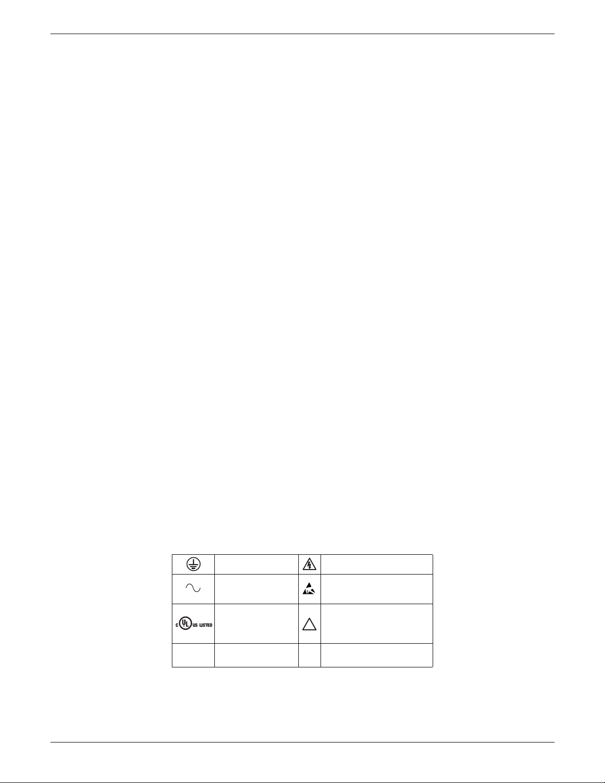
SYMBOLS USED ON THE INSTRUMENT LABELLING
One or more of the symbols below may appear as a part of the instrument labelling.
Protective-conductor
terminal
AC supply only
Underwriters
laboratories listed
mark, for Canada and
the U.S.
Do not touch heatsink
;
Hot Surface
Risk of electric shock
Precautions against static
electrical discharge must be
taken when handling this unit.
Refer to the manual for
instructions
Declaration of conformity to
C
REuropen standard
HA179769
Page 12 Issue 11 Dec 15
Page 15

EPOWER CONTROLLER USER GUIDE
USER GUIDE
1 INTRODUCTION
This document describes the installation, operation and configuration of an EPower ‘station’ (Driver Module
plus one or more Power Modules). The Driver Module comes in one version, but the Power Modules are
available in a number of different power ratings, which are identical in operation and configuration, but
which differ in physical size according to the number of phases being controlled and the maximum current
being supplied. All but the 50 Amp and 100 Amp unit come with cooling fans attached.
The Driver Module includes the following analogue and digital inputs and outputs, fitted as standard:
10V supply
Two analogue inputs
One analogue output
Two digital Inputs/Outputs.
One change-over relay under software control, configurable by the user.
Also fitted are a Watchdog relay, a configuration port and an isolated EIA485 port for attaching an optional
Remote Display.
Three further (optional) I/O modules may be fitted, similar to the standard module but with the addition of
an output change-over relay. Other options provide for external voltage and current feedback and for
predictive load management.
Section two of this manual gives connector locations and pinouts.
The operator interface consists of a display comprising four lines of 10-characters (where each character is
formed using a 5 x 7 LCD dot matrix) and four push buttons for navigation and data selection.
1.1 UNPACKING THE UNITS
The units are despatched in a special pack, designed to give adequate protection during transit. If any of the
outer boxes show signs of damage, they should be opened immediately, and the instrument examined. If
there is evidence of damage, the instrument should not be operated and the local representative contacted
for instructions.
After the instrument has been removed from its packing, the packing should be examined to ensure that all
accessories and documentation have been removed. The packing should then be stored against future
transport requirements.
HA179769
Issue 11 Dec 15 Page 13
Page 16
EPOWER CONTROLLER USER GUIDE
A
B
400A
250A
Single-phase power module
mounting shown.
Multi-phase mountings similar
Safety Earth
Power unit
Driver module
500/630A Driver
module bracket
See table 2.2.1 for
Safety Earth details
2 INSTALLATION
2.1 MECHANICAL INSTALLATION
2.1.1 Fixing details
Units are designed to operate at an operating temperature not exceeding 40°C (unless the modules are derated - see specification). Units must be installed in a fan-cooled cabinet (with fan failure detection or thermal
safety cutout). Condensation and conductive pollution should be excluded to IEC 60664-1 pollution degree
2. The cabinet must be closed and connected to the protective earth according to IEC 60634 or applicable
national standard.
Units must be mounted with the heat sink vertical with no obstructions above or below which impede the
airflow. Where more than one set of modules is enclosed in the same cabinet, they must be mounted such
that air from one unit is not drawn in by another mounted above it. An air gap of at least 5 cm should be
maintained between adjacent sets of modules.
The units are designed for fitting to the front face of a mounting panel using the fixings supplied. The
thyristor power modules are heavy, so a Health and Safety risk assessment should be carried out before
personnel attempt to lift the units. It should also be ensured, prior to fitting, that the mechanical strength of
the panel is sufficient for the mechanical load being applied. Table 2.1.1 gives the weights of the various
units.
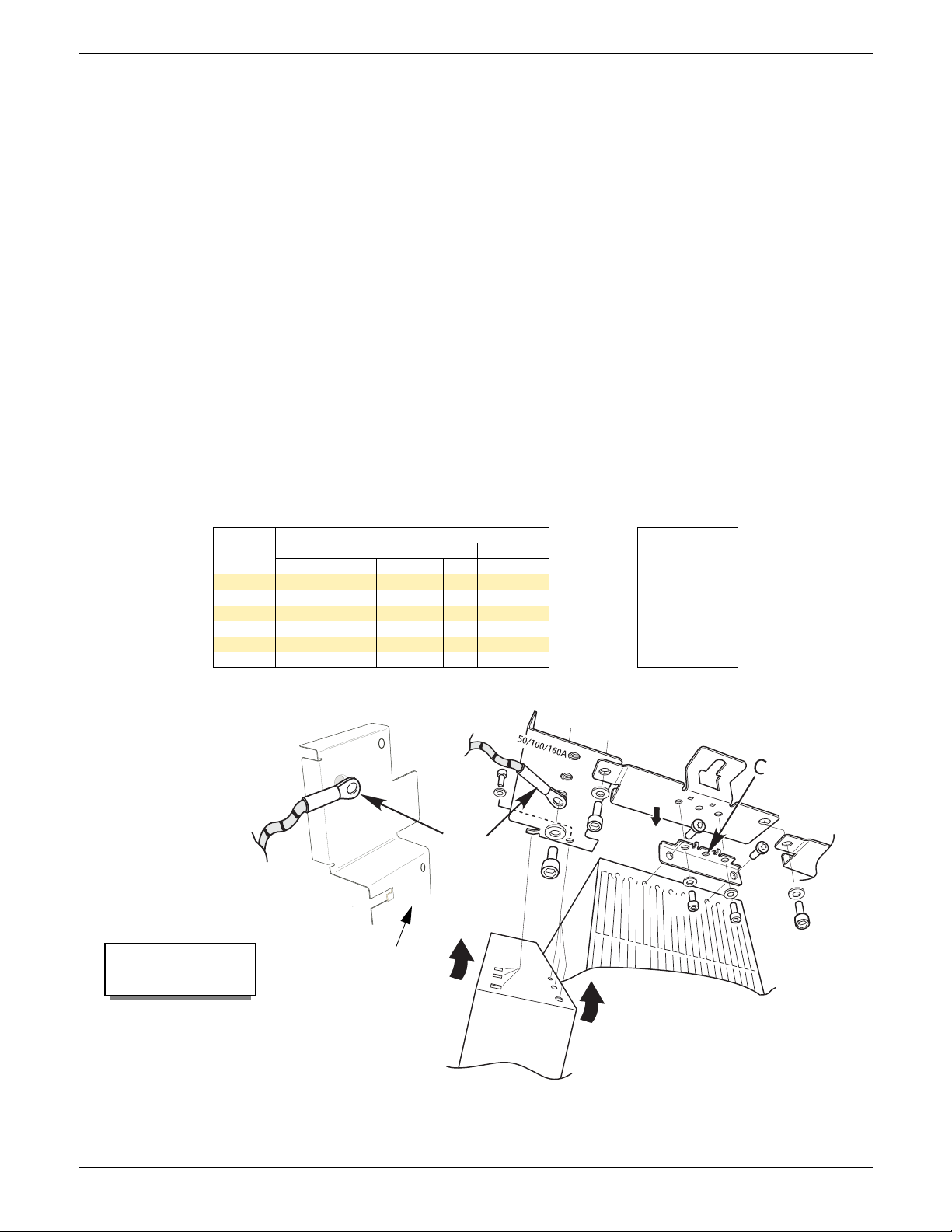
GENERAL
Figure 2.1.1a, below, shows details of a generalised mechanical assembly for the top of the units. Assembly
details for the bottom brackets is similar, except that there is no safety earth fixing. The power module shown
is a 400 Amp unit for which the module is fixed to the support brackets using holes A and B. Lower current
power modules use only one screw (C) to secure the module to the support bracket.
Weight (including 2 kg (4.4 lb) for driver module)
Current
50/100 A 6.5 14.3 11.0 24.3 15.5 34.2 20.0 44.1
160 A 6.9 15.2 11.8 26.0 16.7 36.8 21.6 47.6
250 A 7.8 17.2 13.6 30.0 19.4 42.8 25.2 55.6
400 A 11.8 26.0 21.6 47.6 31.4 69.2 41.2 90.8
500 A 14.0 30.9 26.0 57.3 38.0 83.8 50.0 110.2
630 A 14.5 32.0 27.0 59.5 39.5 87.1 52.0 114.6
1 phase 2 phases 3 phases 4 phases
kg lb kg lb kg lb kg lb
Table 2.1.1 Unit Weights
Weights
± 50gm (2 oz)
lb oz
0.1
0.2
0.3
0.4
0.5
0.6
0.7
0.8
0.9
1.6
3.2
4.8
6.4
8.0
9.6
11.2
12.8
14.4
Page 14 Issue 11 Dec 15
Figure 2.1.1a Bracket fixing details
HA179769
Page 17
EPOWER CONTROLLER USER GUIDE
Recommended fixing bolt size = M6
Cable entry
21.5 (0.85)
Front view
Dimensions in millimetres (inches)
View on underside
Door
(open)
252.2 mm (9.93 in)
317 mm (12.480 in)
330 mm (12.99 in)
Cable exit/entry
194.4 mm (7.65 in)
Communications
Insert uninsulated 5mm
(1/4 in) screwdriver here,
and pull down to release
door
Insert uninsulated 5mm
(1/4 in) screwdriver here,
and pull down to release
door
Insert uninsulated 5mm
(1/4 in) screwdriver here,
and pull down to release
door
Safety earth (M6)
Recommended tightening
torque = 5 Nm (3.7 ft lb)
2.1.1 FIXING DETAILS (Cont.)
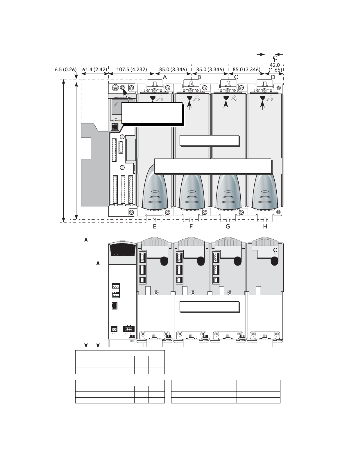
Figures 2.1.1a to 2.1.1f show fixing centres and other mechanical details for the various modules.
Overall Widths (mm)
No of phases123 4
Door closed 149.5 234.5 319.5 404.5
Door open 211.0 296.0 381.0 466.0
Overall Widths (inches) Upper bracket Lower bracket
No of phases 1 2 3 4 2-phase Use A and B Use E and F
Door closed 5.89 9.23 12.58 15.93 3-phase Use A, B and C Use E and G
Door open 8.31 11.65 15.00 18.35 4-phase Use A, B, C and D Use E, F, G and H
Note: Units are shown with individual mounting
brackets. Multi-phase units come supplied with
two, three or four phase brackets as appropriate.
See table below for details.
Figure 2.1.1b Fixing details (50 Amp and 100 Amp units)
HA179769
Issue 11 Dec 15 Page 15
Page 18
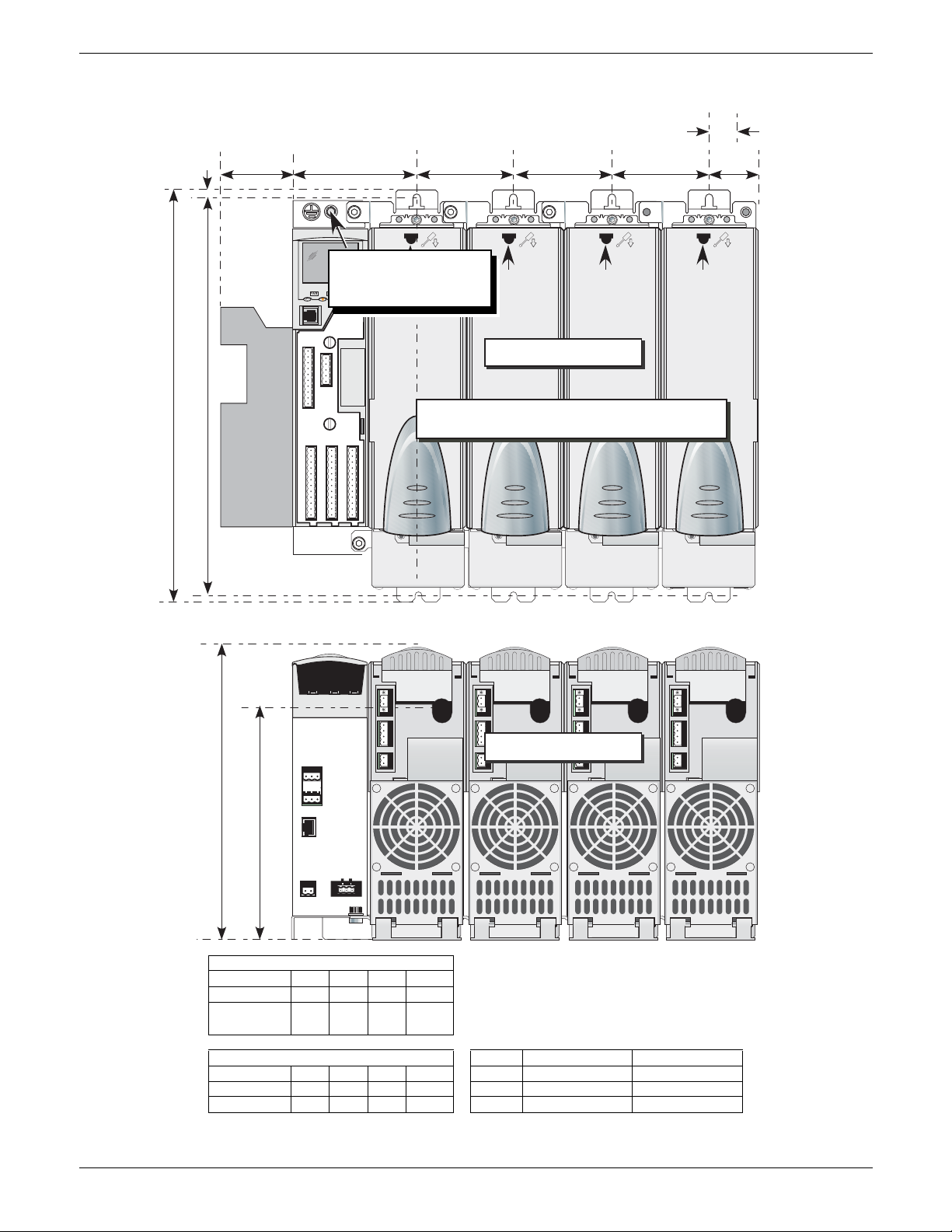
2.1.1 FIXING DETAILS (Cont.)
Insert 5mm screw-
driver here, and pull
down
to release door
85.0 (3.346)85.0 (3.346)85.0 (3.346)107.5 (4.232)61.4 (2.42)
42.0
(1.65)
6.5 (0.26)
A
B
C
D
N
L
NLE
E
G
F
H
C
L
C
L
Recommended fixing bolt size = M6
Cable entry
21.5 (0.85)
Front view
Dimensions in millimetres (inches)
View on underside
Door
(open)
252.2 mm (9.93 in)
348 mm (13.70 in)
361 mm (14.21 in)
Cable exit/entry
194.4 mm (7.65 in)
Communications
Insert uninsulated 5mm
(1/4 in) screwdriver here,
and pull down to release
door
Insert uninsulated 5mm
(1/4 in) screwdriver here,
and pull down to release
door
Insert uninsulated 5mm
(1/4 in) screwdriver here,
and pull down to release
door
Safety earth (M6)
Recommended tightening
torque = 5 Nm (3.7 ft lb)
EPOWER CONTROLLER USER GUIDE
Overall Widths (mm)
No of phases123 4
Door closed 149.5 234.5 319.5 404.5
Door open 211.0 296.0 381.0 466.0
No of phases 1 2 3 4 2-phase Use A and B Use E and F
Door closed 5.89 9.23 12.58 15.93 3-phase Use A, B and C Use E, F and G
Door open 8.31 11.65 15.00 18.35 4-phase Use A, B, C and D Use E, F, G and H
Overall Widths (inches) Upper bracket Lower bracket
Note: Units are shown with individual
mounting brackets. Multi-phase units come
supplied with two, three or four phase
brackets as appropriate. See table below for
details.
Figure 2.1.1c Fixing details (160 Amp unit)
HA179769
Page 16 Issue 11 Dec 15
Page 19
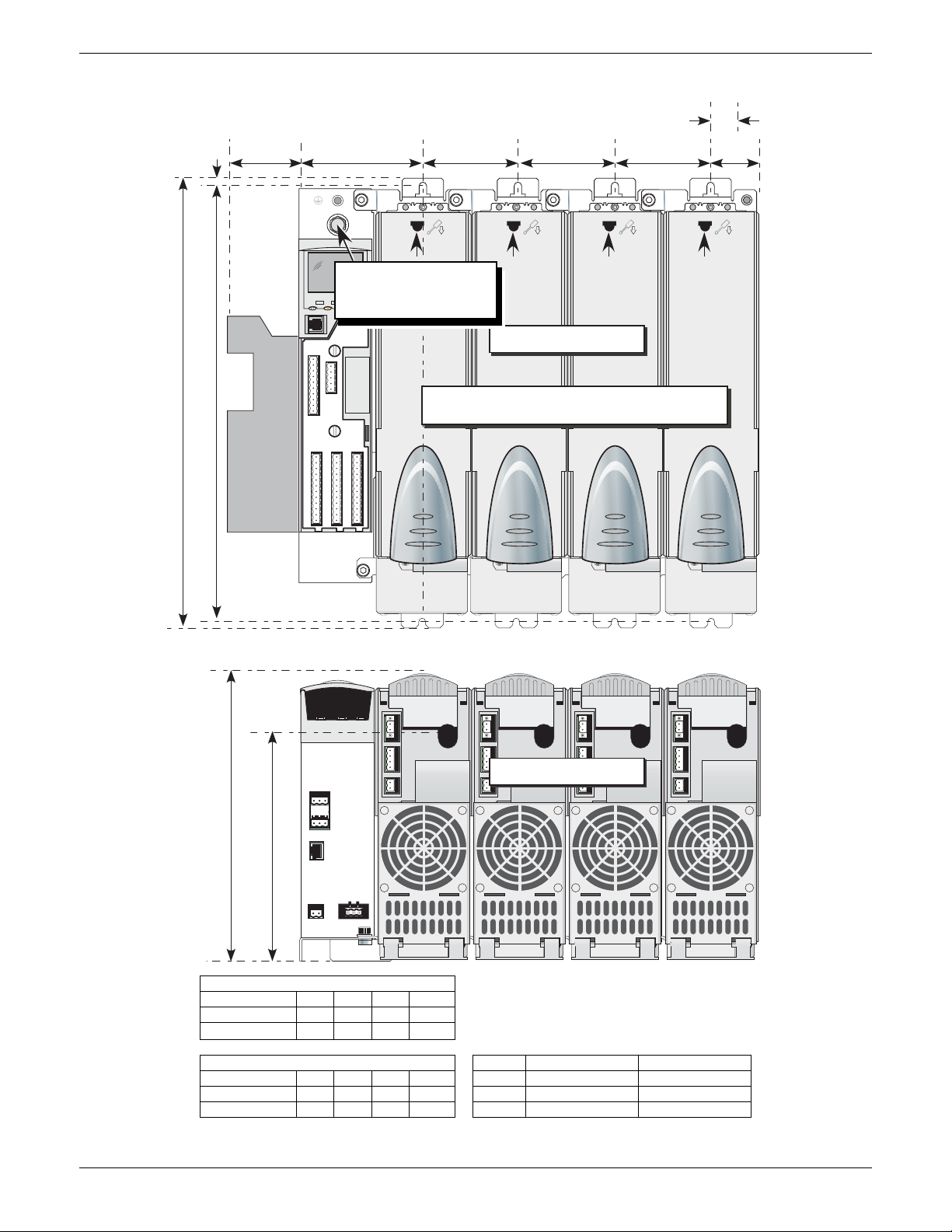
2.1.1 FIXING DETAILS (Cont.)
N
L
NLE
E
G
F
H
C
L
A
B
C
D
85.0 (3.346)85.0 (3.346)85.0 (3.346)107.5 (4.232)61.4 (2.42)
42.0
(1.65)
6.5 (0.26)
PWR LOC ALM
Recommended fixing bolt size = M6
Cable entry
21.5 (0.85)
Front view
Dimensions in millimetres (inches)
View on underside
Door
(open)
252.2 mm (9.93 in)
388 mm (15.276 in)
401 mm (15.79 in)
Cable exit/entry
194.4 mm (7.65 in)
Communications
Insert uninsulated 5mm
(1/4 in) screwdriv er here,
and pull down to release
door
Insert uninsulated 5mm
(1/4 in) screwdriver here,
and pull down to release
door
Insert uninsulate d 5mm
(1/4 in) screwdriver here,
and pull down to release
door
Safety earth (M8)
Recommended tightening
torque = 12.5 Nm (9.2 ft lb)
EPOWER CONTROLLER USER GUIDE
HA179769
No of phases123 4
Door closed 149.5 234.5 319.5 404.5
Door open 211.0 296.0 381.0 466.0
No of phases 1 2 3 4 2-phase Use A and B Use E and F
Door closed 5.89 9.23 12.58 15.93 3-phase Use A, B and C Use E, F and G
Door open 8.31 11.65 15.00 18.35 4-phase Use A, B, C and D Use E, F, G and H
Overall Widths (mm)
Overall Widths (inches) Upper bracket Lower bracket
Note: Units are shown with individual mounting
brackets. Multi-phase units come supplied with
two, three or four phase brackets as
appropriate. See table below for details.
Figure 2.1.1d Fixing details (250 Amp unit)
Issue 11 Dec 15 Page 17
Page 20
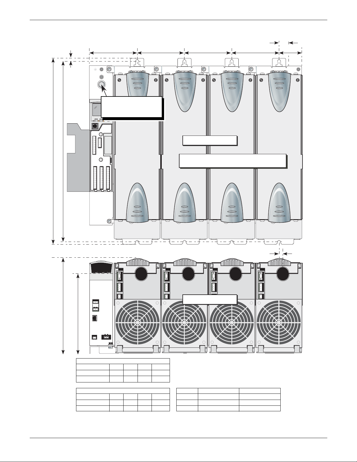
EPOWER CONTROLLER USER GUIDE
PWR LOC ALM
8.5 (0.33)
NLNLE
AB CD
EFGH
62 (2.44)
Recommended fixing bolt size = M8
Line entry 25 (0.98)
Front view
Dimensions in millimetres (inches)
View on underside
Door
(open)
252.2 mm (9.93 in)
474.5 mm (18.681 in)
489.5 mm (19.28 in)
Cable exit/entry
208.4 mm (8.20 in)
Communicatio
127.5mm (5.02in) 125mm (4.921in) 125mm (4.921in) 125mm (4.921in)
Load entry 10mm (0.39in)
Safety earth (M10)
Recommended tightening
torque = 15 Nm (11.1 ft lb)
2.1.1 DIMENSIONAL DETAILS (Cont.)
Overall Widths (mm)
No of phases123 4
Door closed 189.5 314.5 439.5 564.5
Door open 251.0 376.0 501.0 626.0
Overall Widths (inches) Upper bracket Lower bracket
No of phases 1 2 3 4 2-phase Use A and B Use E and F
Door closed 7.46 12.38 17.30 22.22 3-phase Use A, B and C Use E, F and G
Door open 9.88 14.80 19.72 24.65 4-phase Use A, B, C and D Use E, F, G and H
Note: Units are shown with individual mounting
brackets. Multi-phase units come supplied with
two, three or four phase brackets as
appropriate. See table below for details.
Figure 2.1.1e Fixing details (400 Amp unit)
Page 18 Issue 11 Dec 15
HA179769
Page 21
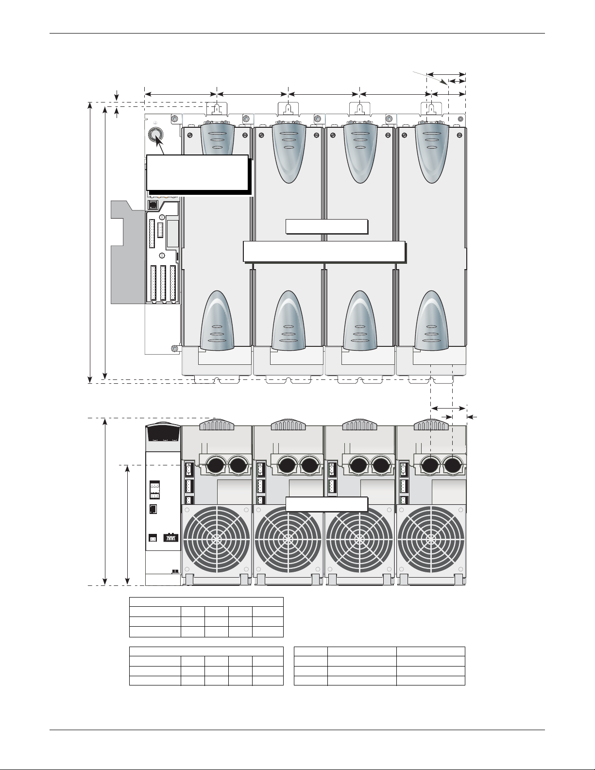
EPOWER CONTROLLER USER GUIDE
Communications
PWR LOC ALM
8.5 (0.33)
62 (2.44)
NLNLE
AB CD
EFGH
63 (2.48)
25
(0.98)
30
(1.18)
68 (2.68)
Recommended fixing bolt size = M8
Line cable entry
Front view
Dimensions in millimetres (inches)
View on underside
Door
(open)
296 mm (11.65 in)
474.5 mm (18.681 in)
489.5 mm (19.27 in)
Cable exit/entry
212 mm (8.35 in)
Communicatio
127.5mm (5.02in) 125mm (4.921in) 125mm (4.921in) 125mm (4.921in)
Load cable entry
Safety earth (M12)
Recommended tightening
torque = 25 Nm (18.4 ft lb)
2.1.1 DIMENSIONAL DETAILS (Cont.)
Overall Widths (mm)
No of phases123 4
Door closed 189.5 314.5 439.5 564.5
Door open 251.0 376.0 501.0 626.0
Overall Widths (inches) Upper bracket Lower bracket
No of phases 1 2 3 4 2-phase Use A and B Use E and F
Door closed 7.46 12.38 17.30 22.22 3-phase Use A, B and C Use E, F and G
Door open 9.88 14.80 19.72 24.65 4-phase Use A, B, C and D Use E, F, G and H
Note: Units are shown with individual
mounting brackets. Multi-phase units come
supplied with two, three or four phase brackets
as appropriate. See table below for details.
Figure 2.1.1f Fixing details (500 Amp/630A units)
HA179769
Issue 11 Dec 15 Page 19
Page 22
EPOWER CONTROLLER USER GUIDE
View on underside
Supply output socket
for power module fan(s)
Supply in
Driver module Power module Power module Power module
Safety Earth
Enable
interlock
SK1
(part of)
Internal
connection
Internal
connection
SK9 not used
with 50/100A
power modules
Fuse (3A)
Supply
voltage
Slow blow
Fan cassette Fan cassette Fan cassette
Fan looms supplied with the modules
To PSU
Internal connections
diagrammatic only
Integral with fan
Integral with fan
Integral with fan
2.2 ELECTRICAL INSTALLATION
2.2.1 Driver Module
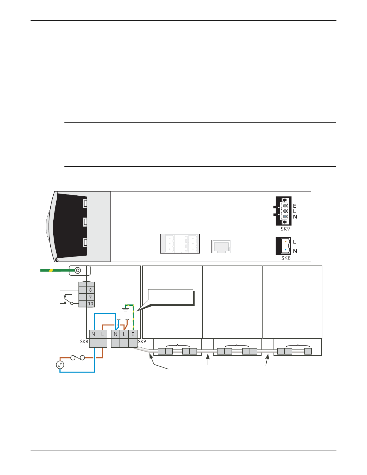
SUPPLY VO LTAG E
The Line and neutral supply voltage connections are terminated using a 2-way connector (SK8), located on
the underside of the unit, as shown in figure 2.2.1a, below. It is recommended that a 3 Amp slow-blow fuse
be incorporated in order to protect the supply voltage wiring.
The Auxiliary (Fan) supply is Installation category II. U.L.: supply to Auxiliary (Fan) supply shall be provided
by isolated transformer secondary grounded protected by a Listed 20A branch circuit fuse.
FAN SUPPLIES
CAUTION
The Driver Module power supply is capable of working from any supply voltage between 85V ac
265V ac. The fans (if fitted) on the power modules are specified for use at 115V ac or 230V ac, as
defined at time of order. It must therefore be ensured that the fan voltage matches the supply
voltage, or the fan will either fail within a short period, or it will be ineffective at cooling.
The three way connector (SK9) provides supply voltage for cooling fans which are fitted to all power modules
except 50A and 100A modules. Suitable looms (harnesses) for the fans are supplied with the units. SK9 is
not used for 50/100A modules, because there are no cooling fans.
ENABLE INPUT
In order for the power module thyristors to operate, the Enable input to the driver module must be valid, In
the default configuration, this is achieved by shorting pins 8 and 10 of SK1 (Digital input 1 - figure 2.2.1b),
or by using a User Value block to apply a logic high to the enable input to the relevant firing block in iTools.
If required, DI1 can be reconfigured as a voltage input, and in this case it requires a high signal (figure 2.2.1c)
to be applied to SK1 pin8 with the relevant zero voltage connected to pin 10.
Page 20 Issue 11 Dec 15
Figure 2.2.1a Driver module wiring
HA179769
Page 23
EPOWER CONTROLLER USER GUIDE
2.2.1 Driver Module (Cont.)
SAFETY EARTH
Before any other connection is made, the protective earth terminal shall be connected to a protective
conductor.
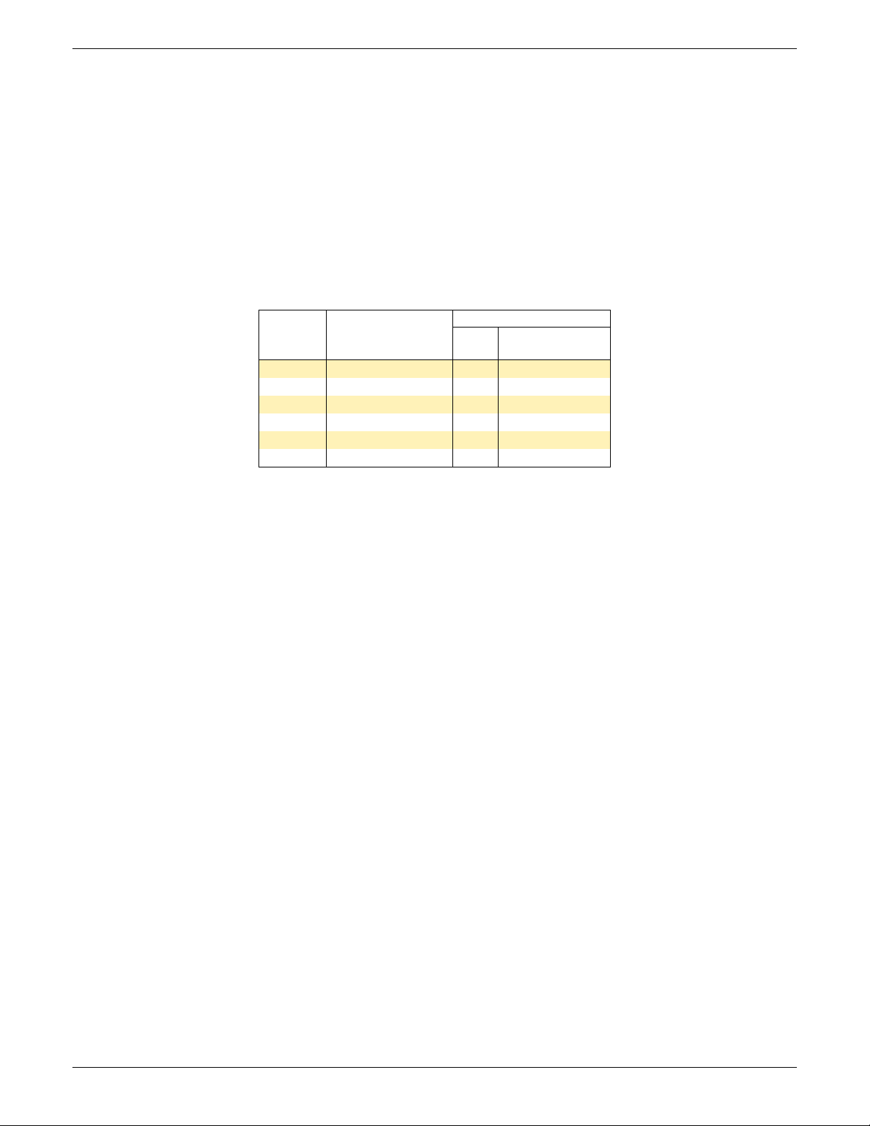
The safety earth connection for the driver/power module set is made to the mounting bracket above the unit
as shown in figures 2.1.1a to 2.1.1f, above.
The connection must be made using the correct size of terminal and correct gauge of cable, as given in table
2.2.1 below.
UL: Wire conductor cross sections must comply with NEC requirements. Used cables must be rated 75°C
stranded copper only. Connection must be made by using listed lugs
The earth connection should be tightened at the torque defined in table 2.2.1.
perform regular inspection of the earth tightening
It is recommended to
Max. load
current
50/100A
160A
250A
400A
500A
630A
Minimum earth
cable cross-section.
2
25 mm
2
35 mm
2
70 mm
120 mm
150 mm
185 mm
Table 2.2.1 Safety Earth details
2
2
2
Earth Terminal
Size
M6 5 Nm (3.7 ft lb.)
M6 5 Nm (3.7 ft lb)
M8 12.5 Nm (9.2 ft lb)
M10 15 Nm (11.1ft lb)
M12 25 Nm (18.4 ft lb)
M12 25 Nm (18.4 ft lb)
Tightening
torque
Any interruption of the protective conductor inside or outside the apparatus, or disconnection of the
protective earth terminal is likely to make the apparatus dangerous under some fault conditions. Intentional
interruption is prohibited.
Whenever it is likely that protection has been impaired, the unit shall be made inoperative, and secured
against accidental operation. The manufacturers nearest service center should be contacted for advice.
HA179769
Issue 11 Dec 15 Page 21
Page 24
EPOWER CONTROLLER USER GUIDE
PWR LOC ALM
NC
Com
NO
14 11 12
04 01 02
View on
underside
Front
Configuration
port (EIA232)
Load
management
Communications
Relay 1
Watch dog
relay
Remote display
(isolated
EIA485)
SIGNAL WIRING
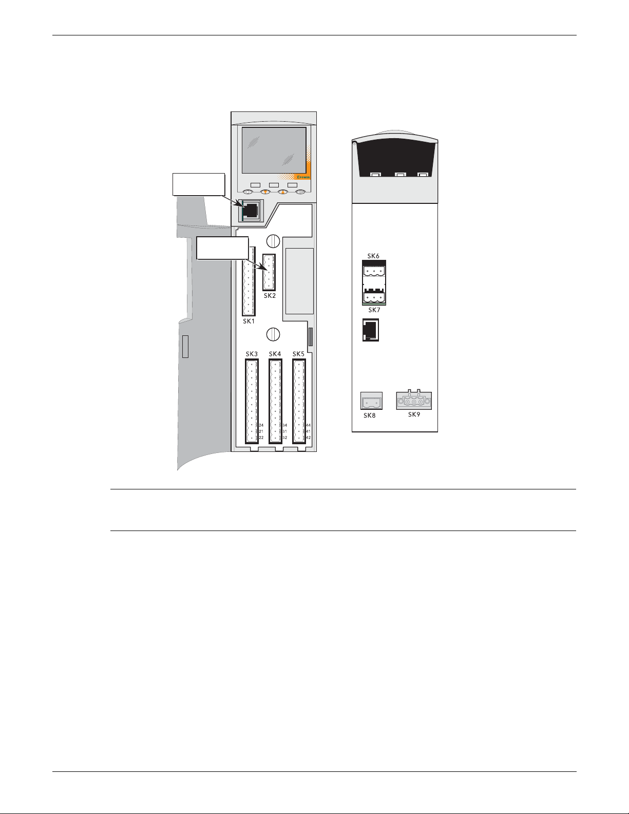
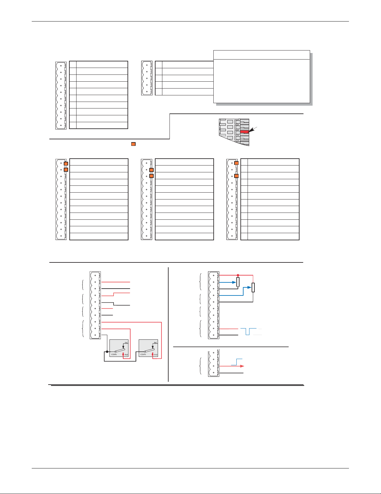
Figure 2.2.1b shows the location of the various connectors; pinouts and typical wiring for SK1 (fitted as
standard) are shown in figure 2.2.1c. Wiring for optional I/O units (SK 3 to SK5) is similar, except that they
contain a relay in addition to the analog and digital circuits, and the digital circuits are inputs only.
Note: It is physically possible to insert an RJ11 plug into an RJ45 socket. Care must therefore be
taken to ensure that the Configuration port cable is not mistakenly plugged into an RJ45
communications connector (if fitted) or the Remote display connector.
Figure 2.2.1b Connector locations
HA179769
Page 22 Issue 11 Dec 15
Page 25
1
SK2
5
1
2
3
4
5
1
SK1
1
2
3
4
5
6
7
8
9
10
1
SK3
1
2
3
4
5
6
7
8
9
10
11
12
12
1
SK4
1
2
3
4
5
6
7
8
9
10
11
12
12
1
SK5
1
2
3
4
5
6
7
8
9
10
11
12
12
1
2
3
+
-
4
5
6
+
-
7
8
SK1
9
10
I/ O 1
I/ O 2
0 V
8
9
10
I/ O 1
I/ O 2
0 V
1
2
3
+
-
4
5
6
+
-
7
8
SK1
9
10
+
0V
I/ O 1
I/ O 2
0 V
SK1
Standard I/O
Predictive Load
Management
Relevant manual sections
Analogue I/P Section 6.4
Analogue O/P Section 6.5
Digital I/O Section 6.9
Relays Section
6.21
= Polarising pin
Mating
connector
(section)
Pol arising key
(Position 3)
Optional I/O 1 Optional I/O 2 Optional I/O 3
Polarising pins:
Fixed connector: pins 1 and 2;
Mating connector: pin 3
Polarising pins:
Fixed connector: pins 2 and 3;
Mating connector: pin 1
Polarising pins:
Fixed connector: pins 1 and 3;
Mating connector: pin 2
+10V output
V input
mA input
(240R internal shunt)
mA or Voltage output
+10V output
Analogue
input 1
Analogue
input 2
Analogue
output 1
Digital I/O
(Contact
Analogue
input 1
Analogue
input 2
Analogue
output 1
Digital I/O
(logic input)
Digital I/O
(output)
potentiometric
inputs
15V 10mA current source
I/O 2 shown; I/O 1 similar
I/O 2 shown; I/O 1 similar
High (4 to 30 V)
Low (-30V to +2 V)
-30V < Vin < +2V = Low
+4V < Vin < 30V = High
+2 < Vin < 4V = not defined
Notes:
1. Analogue input type selected during configuration as one of: 0 to 5V, 0 to 10V, 1 to 5V, 2 to 10V, 0 to 20mA, 4 to 20
mA
2. Analogue output type selected during configuration as one of : 0 to 5V, 0 to 10V, 0 to 20mA, 4 to 20mA.
Resolution 12 bits; accuracy ±1% scale.
3. Each analogue input -ve terminal is individually connected to 0V via a 150 Ohm resistor.
+10 Volts out
Analogue i/p 1 +
Analogue i/p 1
Analogue i/p 2 +
Analogue i/p 2 Analogue o/p 1 +
Analogue o/p 1 0V
Digital i/o 1 +
Digital i/o 2 +
Digital i/o 0V
+10 Volts out
Analogue i/p 3 +
Analogue i/p 3 Analogue o/p 2 +
Analogue o/p 2 0V
Digital input 3 +
Digital input 4 +
Digital 0V
Not used
Relay 2 No (24)
Relay 2 Com (21)
Relay 2 NC (22)
Termin a t o r A
Low
Shield
High
Termin a t o r B
+10 Volts out
Analogue i/p 4 +
Analogue i/p 4 Analogue o/p 3 +
Analogue o/p 3 0V
Digital input 5 +
Digital input 6 +
Digital 0V
Not used
Relay 3 No (34)
Relay 3 Com (31)
Relay 3 NC (32)
+10 Volts out
Analogue i/p 5 +
Analogue i/p 5 Analogue o/p 4 +
Analogue o/p 4 0V
Digital input 7 +
Digital input 8 +
Digital 0V
Not used
Relay 4 No (44)
Relay 4 Com (41)
Relay 4 NC (42)
EPOWER CONTROLLER USER GUIDE
2.2.1 Driver Module (Cont.)
HA179769
Issue 11 Dec 15 Page 23
Figure 2.2.1c Drive unit connector pinouts
Page 26
EPOWER CONTROLLER USER GUIDE
NO
Com NC
NO
Com NC
Com
NC
NO
Com
NC
NO
14 11 12
04 01 02
Front
View on
underside
= Polarising pin
Relay 1
Watchdog relay
Watchdog relay
Relay 1
Mating connector polarising pin locations
Watchdog relay
Relay 1
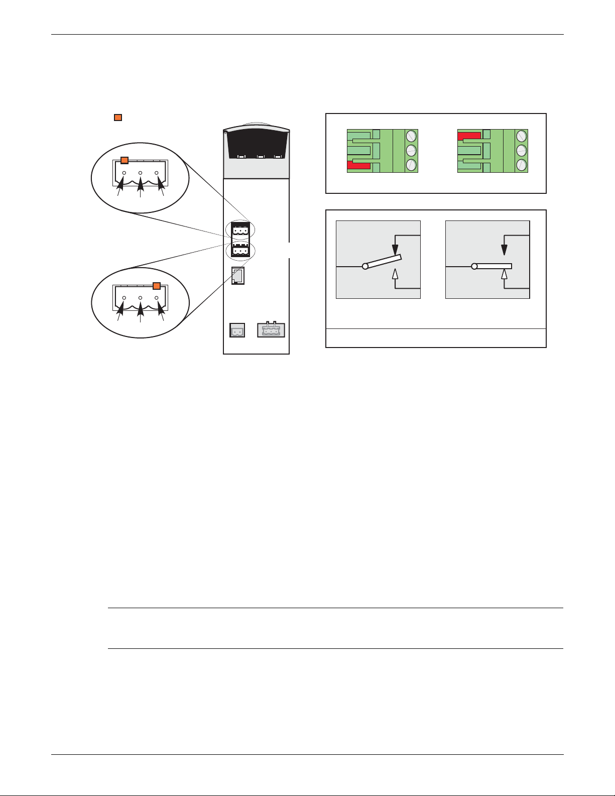
RELAY CONTACT DEFINITIONS
Relay not energised
(Com shorted to NC)
Relay energised
(Com shorted to NO)
2.2.1 Driver Module (Cont.)
WATCHDOG RELAY
The ‘watchdog’ relay is wired to a connector on the underside of the Driver Module (figure 2.2.1d).
Figure 2.2.1d Relay connector location and pinout.
Under normal operating conditions, the watchdog relay is energised (that is the common and normally open
contacts are shorted). Should a system error (listed below) become active (or power to the Driver Module
fail), the relay is de-energised (common and normally closed contacts shorted).
1. Missing mains. One or more Power Module supply voltage lines is missing.
2. Thyristor short circuit*
3. Thyristor open circuit*
4. Fuse Blown. Thyristor-protection fuse ruptured in one or more Power Modules.
5. Unit over temperature
6. Network dips. A reduction in supply voltage exceeding a configurable value (VdipsThreshold), causes
firing to be inhibited until the supply voltage returns to a suitable value. VdipsThreshold represents a
percentage change in supply voltage between successive half cycles, and can be defined by the user
in the Network.Setup menu, as described in section 6.20.2.
7. Supply frequency fault. The supply frequency is checked every half cycle, and if the percentage change
between successive 1/2 cycles exceeds a threshold value (max. 5%), a Mains Frequency System Alarm
is generated. The threshold value (FreqDriftThold) is defined in the Network.Setup menu described in
section 6.20.2.
8. Power Module 24V Failure.
* Note: It is not possible to detect a thyristor short circuit when the unit is delivering 100% output
power. Similarly, it is not possible to detect thyristor open circuit when the unit is delivering 0%
output.
RELAY 1
This relay, supplied as standard, is located adjacent to the watchdog relay (figure 2.2.1d). The energisation/
de-energisation of the relay coil is under software control and is fully configurable by the user. The terms
Normally open (NO) and Normally closed (NC) refer to the relay in its de-energised state. Up to three further
relays are available if optional I/O Modules are fitted (see figure 2.2.1c).
Page 24 Issue 11 Dec 15
HA179769
Page 27
EPOWER CONTROLLER USER GUIDE
1
5
1
SK2
5
1
2
3
4
5
nmax = 64
Station 1 Station 2 Station i Station n
Signal low
Shield
Signal high
Term ina t or A
Signal Low
Shield
Signal High
Term ina t or B
2.2.1 Driver Module (Cont.)
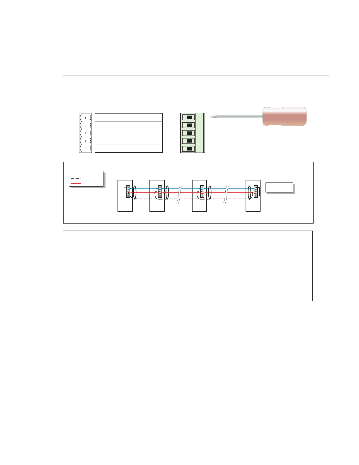
PREDICTIVE LOAD MANAGEMENT OPTION CONNECTOR
This option allows a number of systems to communicate with one another to allow load management
techniques such as Load Sharing and Load Shedding to be implemented. The connector is located as shown
in figure 2.2.1b.
Note: Connecting pins 1 and 5 together has the effect of introducing a terminating (120 Ohm)
resistor across pins 2 and 4. It is recommended that this be done at each end of the transmission
line.
Maximum Trunk line length = 100 metres (328 ft)
Maximum individual drop length = 5 metres (16 ft)
Maximum cumulative drop length = 30 metres (98 ft)
Conductor pair size = 24 gauge (0.25 mm
2
)
Characteristic impedance at 500kHz = 120 Ohms 10%
Nominal capacitance @ 800Hz = ≤40pF
Unbalance capacitance = ≤4 10%pF/m
Capacitance between conductors = 100pF/metre)
Attenuation at 500kHz = 1.64dB/100 metres)
Note: The figures above are for a network of up to 100 metres with up to 64 units
connected. The actual network impedance is a function of cable type, cable length and the
number of units connected. For futher details contact the manufacturer or local agent.
Figure 2.2.1e Predictive Load Management wiring
Load Sharing
In a system with several heating zones, this allows a strategy to be implemented which distributes power over time
in such a way that the overall power consumption remains as steady as possible, thus reducing the peak power
demand of the system.
Load Shedding
In a system with several heating zones, this allows a strategy to be implemented which limits the available load
power at each heating zone and/or switches zones off according to a defined priority level, thus allowing the
maximum running power consumption to be controlled. The total running power is the maximum power supplied
to the loads, integrated over a 50 minute period.
See the Predictive Load Management option description (section 9), for more details.
HA179769
Issue 11 Dec 15 Page 25
Page 28
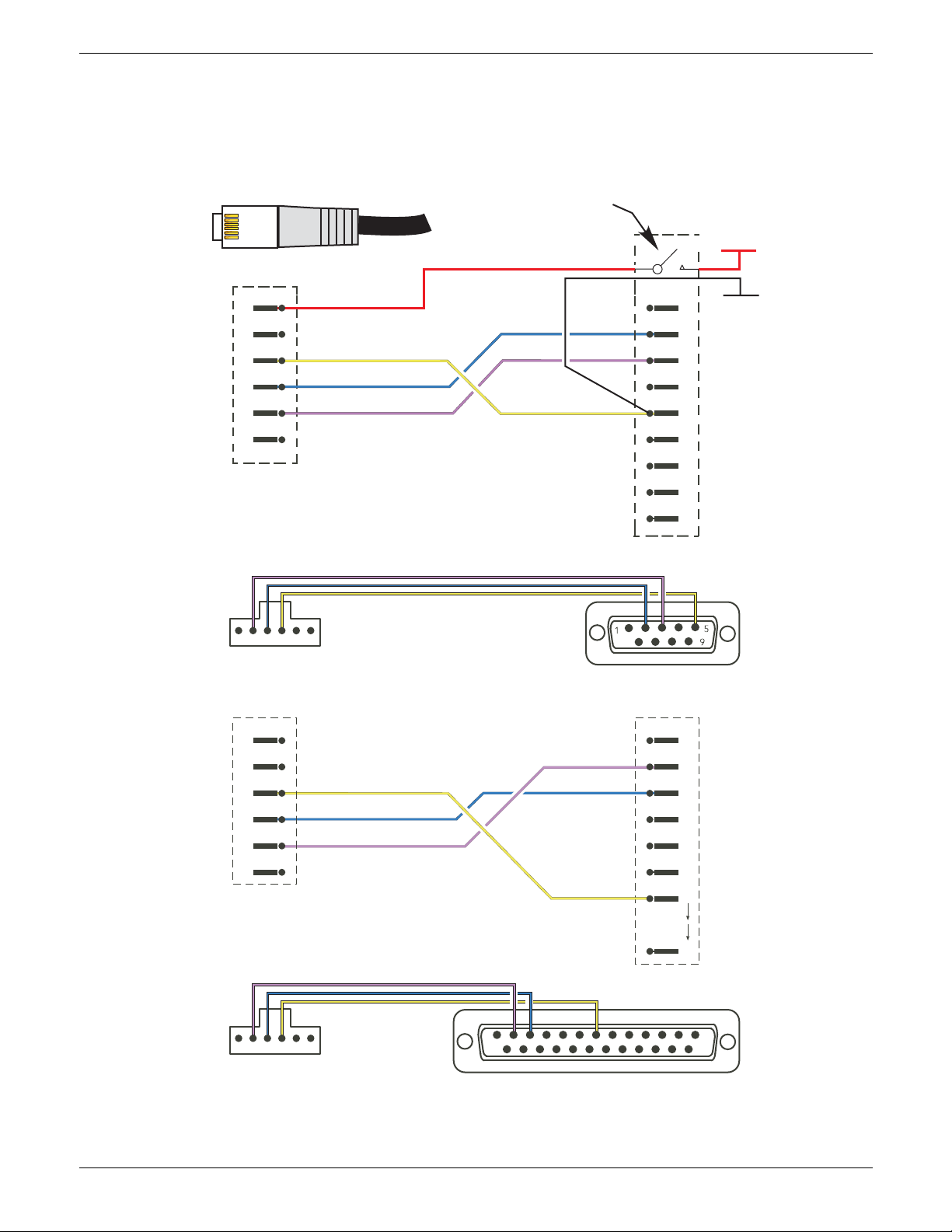
1
6
24 V dc
(N.C.)
0V
Tx
Rx
(N.C.)
1
2
3
4
5
6
61
1
25
Tx
Rx
0V
13
25
61
1
14
7
1
2
3
4
5
6
7
8
9
(N.C)
Rx
Tx
DTR
0V
DSR
RTS
CTS
(N.C)
2
3
4
5
6
7
+24 V
0V
24 V dc
(N.C.)
0V
Tx
Rx
(N.C.)
1
2
3
4
5
6
Optional jack plug
integral with Dtype
Note:
Jack plug option available
from the epower manufacturer
(6-way RJ11 Male to
Processor module)
9-way D-type socket
(To PC EIA232 port)
(6-way RJ11 Male to
Processor module)
25-way D-type socket
(To PC EIA232 port)
REAR VIEW
REAR VIEW
2.2.1 Driver Module (Cont.)
CONFIGURATION PORT
This RJ11 connector located on the front of the Driver Module (figure 2.2.1b) is used for direct connection
to a PC using EIA232C standard.
EPOWER CONTROLLER USER GUIDE
Figure 2.2.1f Configuration port wiring details
Page 26 Issue 11 Dec 15
HA179769
Page 29
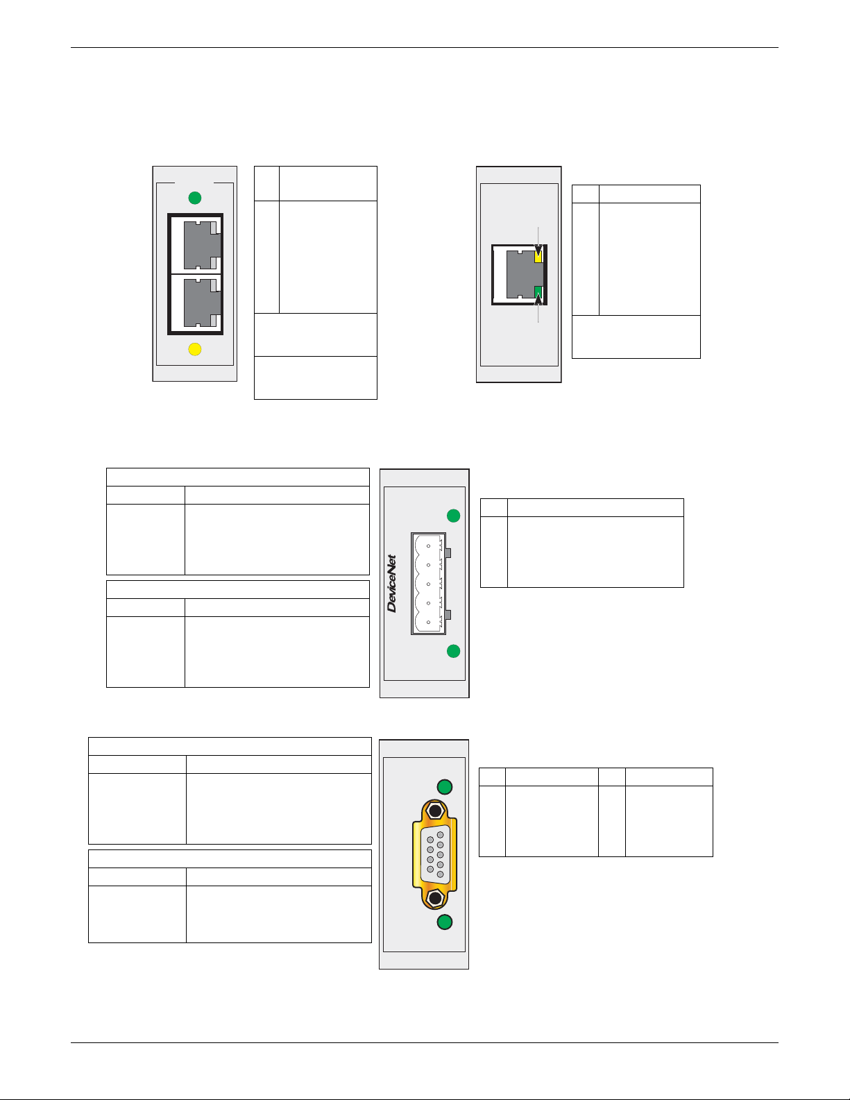
EPOWER CONTROLLER USER GUIDE
1
8
1
8
1
8
PinSignal
(EIA485)
8
7
6
5
4
3
2
1
Reserved
Reserved
N/C
N/C
N/C
Isolated 0V
A
B
Internal connections:
Pin 1 to 5V via 100k
Pin 2 to 0V via 100k
LEDs:
Green = Tx activity
Yellow = Rx activity
Green
Yellow
MODBUS / RTU
Connectors
in parallel
Pin Function
8
7
6
5
4
3
2
1
N/C
N/C
RxN/C
N/C
Rx+
Tx-
Tx+
LEDs:
Green = Tx activity
Yell o w =
Network activity
Figure 2.2.1h Modbus TCP (Ethernet 10baseT) pinout Figure 2.2.1g Modbus RTU pinout
Green
Yellow
MODBUS / TCP
Notes:
1. See DeviceNet specification for power
supply specification
2. During startup, an LED test is
performed, satisfying the DeviceNet
standard.
Pin Function
1
2
3
4
5
V- (negative bus supply voltage)
CAN_L
Cable shield
CAN_H
V+ (positive bus supply voltage).
Network status LED Indication
LED state Interpretation
Off
Steady green
Flashing green
Steady red
Flashing red
Off-line or no power
On-line to 1 or more units
On-line - no connections
Critical link failure
1 or more connections timed out
Module status LED Indication
LED state Interpretation
Off
Steady green
Flashing green
Steady red
Flashing red
No power
Operating normally
Missing or incomplete configuration
Unrecoverable fault(s)
Recoverable fault(s)
Network
Status
Module
Status
5
9
1
6
Notes:
1. Isolated 5 Volts for termination purposes.
Any current drawn from this terminal affects
the total power consumtion.
2. The cable screen should be terminated to
the connector housing.
Pin Function Pin Function
9
8
7
6
N/C
A (RxD -/TxD -)
N/C
+5 V (See note 1)
5
4
3
2
1
Isolated ground
RTS
B (RxD+ / TxD+)
N/C
N/C
OPERATION MODE LED INDICATION
LED state Interpretation
Off
Steady green
Flashing green
Red single flash
Red double flash
Off line or no power
On-line, data exchange
On-line, clear
Param etrisatio n error
PROFIBUS configuration error
STATUS LED INDICATION
LED state Interpretation
Off
Steady green
Flashing green
Steady red
No power or not initialised
Initialised
Diagnostic event present
Exception error
Status
Mode
PROFIBUS / DP
2.2.1 Driver Module (Cont.)
COMMUNICATIONS PINOUTS
Serial communications is discussed in the Communications Manual HA179770. Pinouts for the relevant
protocols are given here for convenience.
HA179769
Issue 11 Dec 15 Page 27
1
5
Figure 2.2.1i DeviceNet® connector pinout
Figure 2.2.1j Profibus connector pinout
Page 30
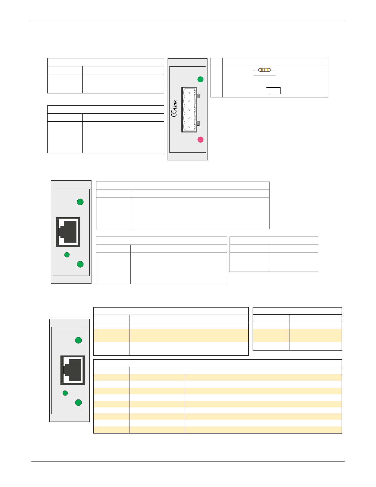
EPOWER CONTROLLER USER GUIDE
5
1
Notes:
1. A 110 Ohm (±5% 1/2 watt) terminating resistor
should be connected across pins 1 and 2 of the
connectors at each end of the transmision line.
2. The cable shield should be connected to pin 4 of
each CC-Link connector.
3. The shield and Protective earth terminals (pins 4
and 5) are internally connected.
Pin Function
1
2
3
4
5
DA (Rx+/Tx+)
DB (Rx-/Tx-)
DG (Signal ground)
SLD (Cable shield)
FG (Protective earth)
‘RUN’ LED Indication
LED state Interpretation
Off
Green
Red
Off-line or no power
Normal operation
Major fault (fatal error)
‘ERR’ LED Indication
LED state Interpretation
Off
Steady red
Flickering red
Flashing red
No error or no power
Exception or fatal event
CRC Error
Station number or Baud rate has
changed since startup.
ERR
RUN
110R, 1/2W, 5%
across pins 1 and 2 of
first and last connec-
SLD and FG connected internally
NS (Network status) LED
LED state Interpretation
Off
Steady green
Flashing green
Steady red
Flashing red
No power or no IP address
On-line; one or more connections established (CIP class 1 or 3)
On-line, no connections enabled
Duplicate IP address (‘fatal’ error)
One or more connections timed out (CIP class 1 or 3)
LINK LED
LED state Interpretation
Off
Steady green
Flickering green
No link; no activity
Link established
Activity in progress
ETHERNET/IP
LINK
MS
NS
MS (Module status) LED
LED state Interpretation
Off
Steady green
Flashing green
Steady red
Flashing red
No power
Controlled by a scanner in Run state
Not configured or scanner in Idle state
Major fault (Exception state, fatal error etc.)
Recoverable fault
PROFINET IO
LINK
MS
NS
NS (Network status) LED
Off
Steady Green
Flashing
Green
No power or no connection
On-line (RUN); connection with I/O controller
established. Controller in ‘Run’ state
On-line (STOP); connection with IO controller
established. Controller in ‘Stop’ state.
LED state Interpretation
LINK LED
InterpretationLED state
Off
Steady Green
Flashing Green
No link; no activity
Link established; no
activity
Activity in progress
MS (Module status) LED
Off
Green steady
Green 1 flash
Green 2 flash
Red steady
Red1 flash
Red 2 flash
Red 3 flash
Red 4 flash
LED state Interpretation
Not initialised
Normal operation
Diagnostic event
Blink
Exception error
Configuration error
IP address error
Station Name error
Internal error
No power, or the module is in ‘SETUP’ or ‘NW_INIT’ state.
The module has shifted from the ‘NW_INIT’ state.
One or more Diagnostic Event present.
Used by engineering tools to identify the node on the network.
The module is in the ‘EXCEPTION’ state.
The Expected Identification differs from the Real Identification.
The IP address is not set.
The Station name is not set.
The module has encountered a major internal fault.
2.2.1 Driver Module (Cont.)
COMMUNICATIONS PINOUTS (Cont.)
Figure 2.2.1k CC-Link connector pinout
Page 28 Issue 11 Dec 15
Figure 2.2.1l Ethernet I/P connector pinout
Figure 2.2.1m Profinet IO connector pinout
HA179769
Page 31
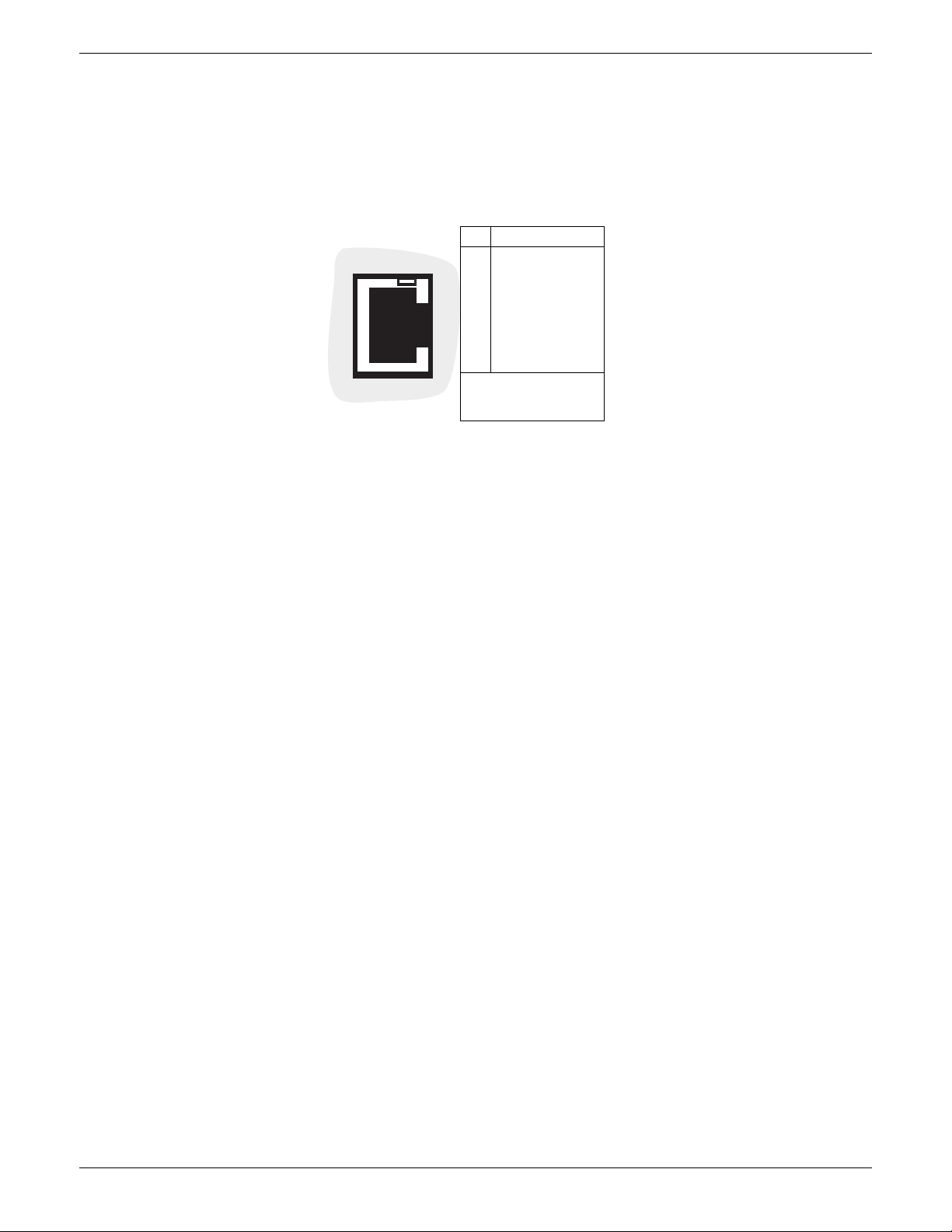
EPOWER CONTROLLER USER GUIDE
Pin Definition
8
7
6
5
4
3
2
1
Reserved
Reserved
N/C
N/C
N/C
Isolated 0V
A
B
Internal connections:
Pin 1 to 5V via 100k
Pin 2 to 0V via 100k
2.2.1 Driver Module (Cont.)
REMOTE PANEL CONNECTOR
Located on the underside of the driver module (figure 2.2.1b) this RJ45 connector supplies isolated 3-wire
EIA485 outputs for an optional remote panel display unit. Figure 2.2.1n gives the pinout. See section 6.6.2
for configuration details. Parity is set to ‘None’. See also Appendix A for details of a suitable remote panel
unit.
8
1
Figure 2.2.1n Remote panel connector
HA179769
Issue 11 Dec 15 Page 29
Page 32
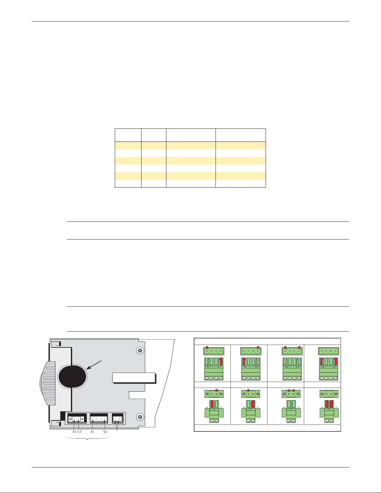
EPOWER CONTROLLER USER GUIDE
V1
V2
V2
V1
V1&V2
V1&V2
I1&I2
I1& I2I1
I2
I2
I1
V1 V2 V1 V2 V1 V2 V1 V2
Load cable exit
Underneath view
Voltage feedback connector
Current feedback connector
Module 1 Module 2 Module 3
Module 4
None
None
None
Load
External feedback
Neutral / phase
reference (Either pin)
Load voltage
None
2.2.2 Power modules
LINE/LOAD CABLES
Line power is routed through the top of the unit and load power emerges from the bottom of the unit.
CE: Wire conductor cross sections must comply with table 9 & 10 of IEC60947-1. Details of recommended
cable sizes etc. are given in table 2.2.2, below.
UL: Wire conductor cross sections must comply NEC requirements. Used cables must be rated 75°C
stranded copper only. Connection must be made by using listed lugs.
Safety earth wiring is discussed in section 2.2.1, above. Figures 2.2.2c to 2.2.2f show typical connection
details.
Power terminals should be tightened according to the torque values defined in table 2.2.2. It is
recommended to perform regular inspection of the power terminals tightening .
Max. load
current
50/100A M8
160A M8
250A M10
400A M12
500A 2 x M12
630A 2 x M12
Te rm in a l
size
Minimum cable
cross-section.
2 x 150 mm
2 x 185 mm
35 mm
70 mm
120 mm
240 mm
2
2
2
2
2
2
Recommended
torque setting
12.5 Nm (9.2 ft lb)
12.5 Nm (9.2 ft lb)
25 Nm (18.4 ft lb)
28.8 Nm (21.2 ft lb)
30 Nm (22.1 ft lb)
30 Nm (22.1 ft lb)
Table 2.2.2 Line/Load termination details
RIBBON CABLE
The ribbon cable is daisy-chained from the Driver Module to the power modules.
Note: In order to maintain protection against damage due to electrostatic discharge, any ribbon
cable which is chafed, scratched or otherwise damaged must be replaced.
EXTERNAL CURRENT FEEDBACK
If the option is fitted, a two-pin connector on the underside of the unit allows the connection of an external
current transformer to measure the load current. The option also includes the Remote Voltage sensing input,
described below. Both connectors have polarising devices fitted (description below) to prevent
misconnection by the user.
The current transformer ratio must be such that its full scale output is 5 Amps. For example when measuring
up to 400 Amps, a 400:5 ratio transformer should be chosen.
External feedback connections must be correctly phased (figure 2.2.2b) or the unit might switch to
full conduction at start-up. See also Appendix B for more details about external feedback.
Page 30 Issue 11 Dec 15
Figure 2.2.2a External feedback, and neutral/phase reference connectors
CAUTION
HA179769
Page 33
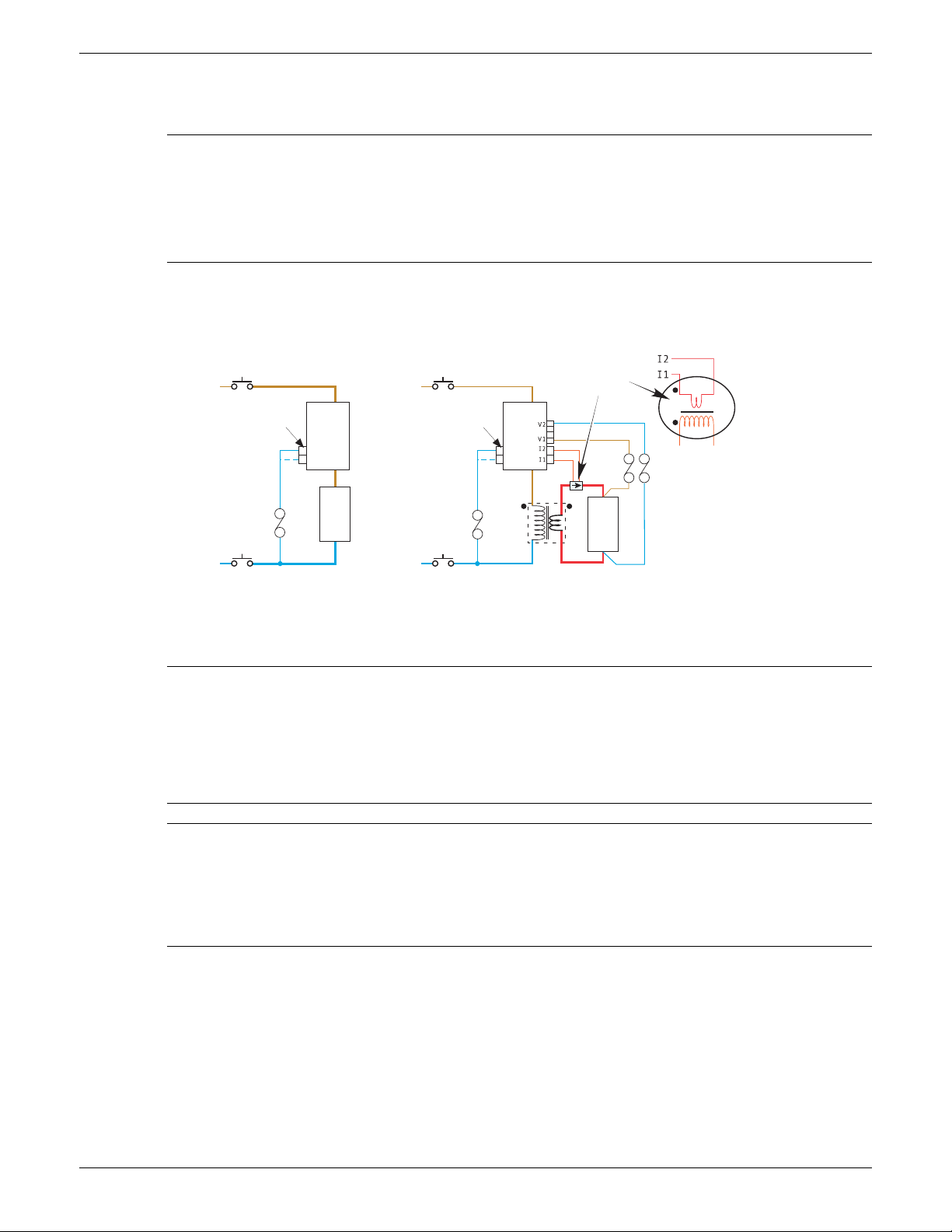
EPOWER CONTROLLER USER GUIDE
Supply
Isolating device
Phase/neutral
reference
Pow er
Module
Load
Fuse
Use either
terminal
Use either
terminal
Return
Isolating device
Phase/neutral
reference
Pow er
Module
Supply
Isolating device
Fuse
Return
Isolating device
Load
Fuse s
Current
transformer
Detail
External feedback connections (Option)
Internal feedback connections (Standard)
Single phase shown; multiple phases similar
Secondary
Primary
2.2.2 POWER MODULES (Cont.)
REMOTE VOLTAGE INPUT
WARNING
It must be ensured that the remote voltage sensing inputs (if fitted) are correctly fused. It is the
responsibility of the user to add branch-circuit protection. Such branch-circuit must comply with
applicable local regulations.
UL: The above mentioned branch-circuit protection is necessary for compliance with National
Electric Code (NEC) requirements.
If the option is fitted, the two end pins of a four-pin connector (figure 2.2.2a) are used for terminating remote
voltage sensing cable. It is recommended that each input be fitted with slow-blow fuse (figure 2.2.2b) of a
lower current rating than that of the sensing cable harness. If the option is fitted, the Current Transformer
input, described above, is also fitted.
Figure 2.2.2b Fusing for remote voltage sensing input and neutral reference inputs
NEUTRAL/PHASE REFERENCE INPUT
WARNING
For 4S, 6D and two-leg configurations the reference input described below is connected to neutral
or to a phase supply as appropriate see figure 2.2.2g for more details. For these configurations a
fuse must be fitted in the reference input circuit. It is the responsibility of the user to add branchcircuit protection. Such branch-circuit must comply with applicable local regulations. UL: The above
mentioned branch-circuit protection is necessary for compliance with National Electric Code (NEC)
requirements.
CAUTION
1. For ‘4S’ and single phase configurations, loss of the neutral supply causes the reference to be lost
as well. For ‘6D’ and ‘two-leg’ configurations, loss of the relevant phase supply also causes the
loss of the reference.
2. The reference connection must be made before power is applied, and not disconnected until
after power has been switched off.
In order to ensure correct firing for 4S, 6D and two-leg configurations, a connection to neutral or to the
relevant phase must be made using the relevant two-pin connector on the underside of the unit (figure
2.2.2a). (Both pins are connected together internally, so either may be used.) This supplies a reference for
voltage measurements within the unit. It is recommended that such inputs be fitted with a suitable slow-blow
fuse, as shown in figure 2.2.2b above and figure 2.2.2g, below). The reference inputs for other
configurations are not connected directly to the supply, and fusing is therefore not required.
The unit has been designed to detect the loss of any of the reference signals and to suspend firing should
any of them ‘fail’. Firing may not be correct during the detection period. As shown in the various figures, the
reference connection is taken ‘down-line’ of any isolating device, so that should this device (e.g. contactor)
‘trip out’, then the controller will be able to detect the loss of reference signal and shut down appropriately.
HA179769
Issue 11 Dec 15 Page 31
Page 34
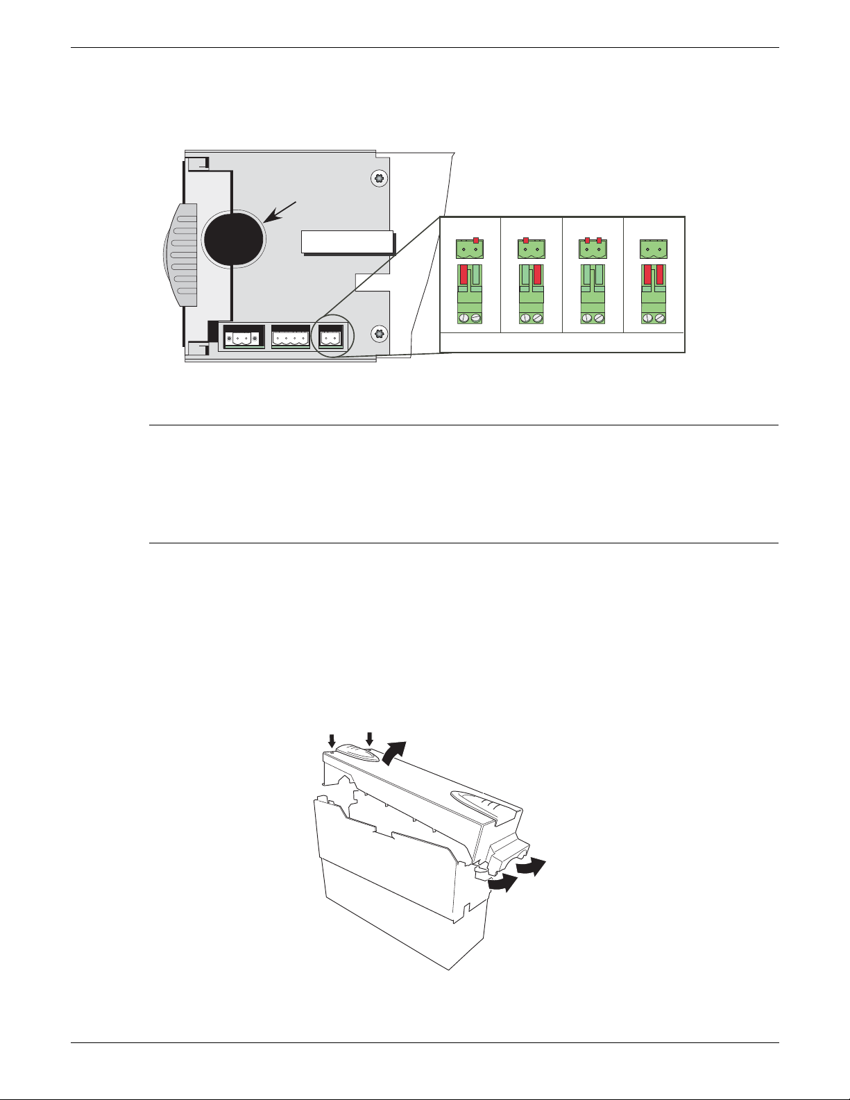
EPOWER CONTROLLER USER GUIDE
Load cable exit
Underneath view
Module 1
Neutral/phase reference connector
Module 2 Module 3 Module 4
2.2.2 POWER MODULES (Cont.)
NEUTRAL/PHASE REFERENCE INPUT (Cont.)
Polarising pins are fitted to the connectors as shown in the figure below.
Neutral/phase reference connector polarising pins
ACCESS TO LINE AND LOAD TERMINATIONS
WARNING
LETHAL VOLTAGES of up to 690 V ac appear at large areas of exposed metal when the doors to the
power modules are open. It must be ensured by the user that the units are isolated from all
hazardous voltages, and secured against accidental application of power, before the doors are
opened. It is recommended that voltage checks are carried out within the unit (if wired), or at the
supply and load cables before any work is started.
For 50A, 100A, 160A and 250A units, to remove the doors, insert a non-insulated screwdriver with a 5 mm
flat blade into the slot near the top of the door, and gently lever downwards to disengage the catch, and pull
the top of the door away from the unit. Once free, the door can be lifted off its pivots which are located at
the bottom of the case.
For the 400A unit, the door is released by undoing the two fasteners near the top of the door and then
pulling the top of the door away from the unit. Once free, the door can be lifted off its pivots which are
located at the bottom of the case.
The 500A/630Amp module door is similar to the 400Amp module, but once released, the bottom of the
door is pulled downwards to disengage it from its securing lugs, not lifted off, as described for the 400A
module.
Door removal (500/630A units)
HA179769
Page 32 Issue 11 Dec 15
Page 35
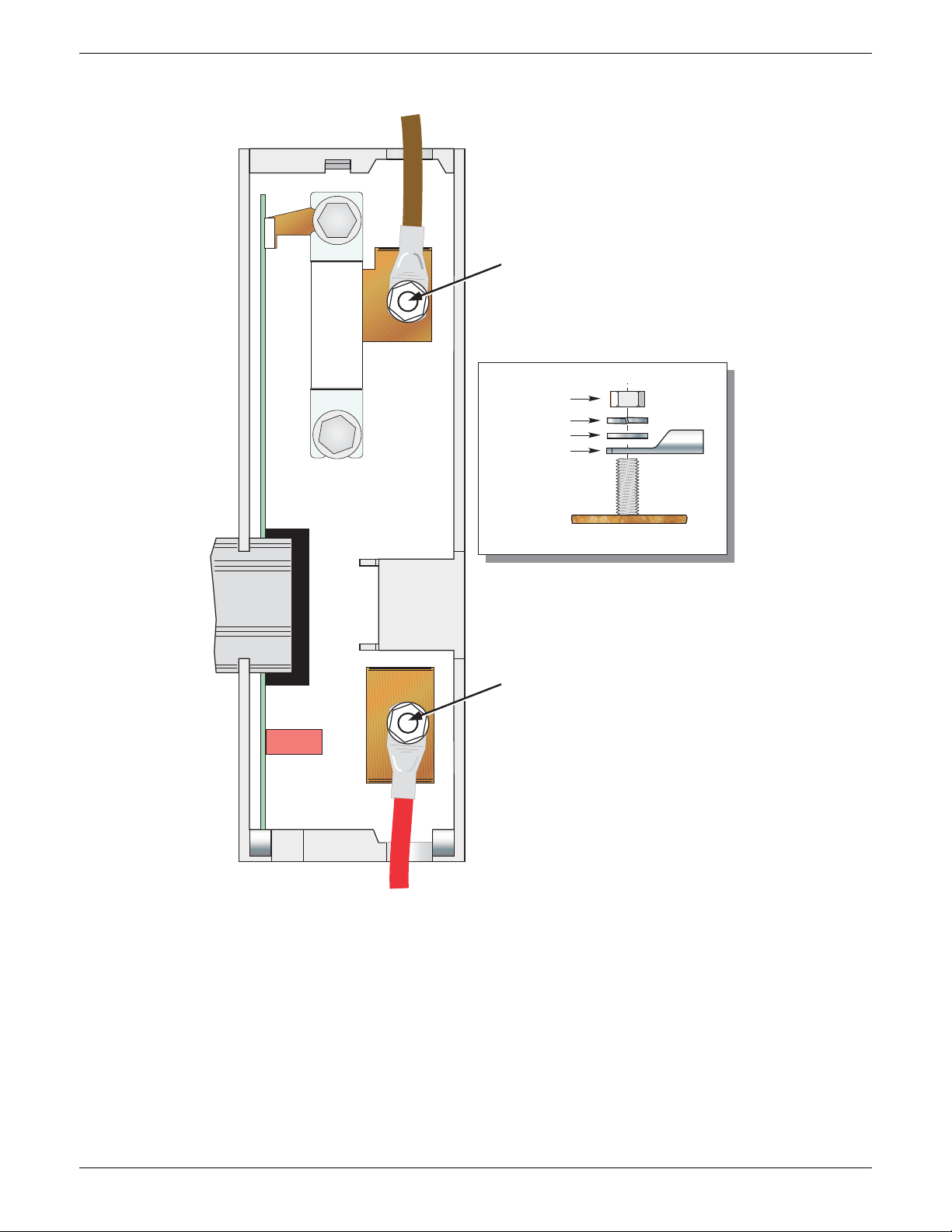
2.2.2 POWER MODULES (Cont.)
Supply
voltage
termination
Fuse
Ribbon
cable
(in)
Cable termination recommended
torque:
50A/100A/160A = 12.5Nm
250A = 25Nm
Nut
Spring washer
Washer
Crimp tag
Termination detail
Load
termination
EPOWER CONTROLLER USER GUIDE
Figure 2.2.2c Line and load termination (50A, 100A and 160A units) (250A units similar)
HA179769
Issue 11 Dec 15 Page 33
Page 36
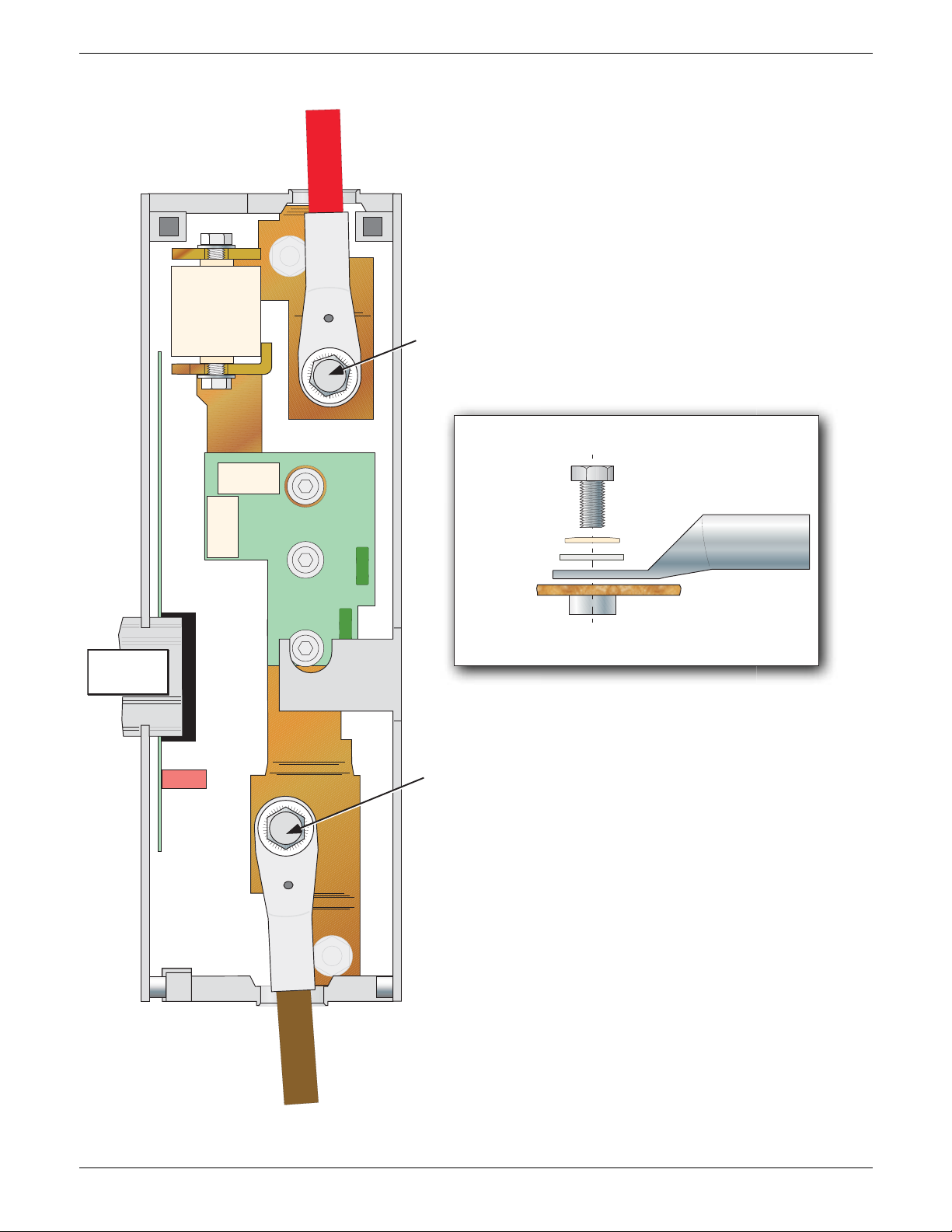
2.2.2 POWER MODULES (Cont.)
Supply
voltage
termination
Load
termination
Ribbon
cable (in)
Recommended torque = 28.8 Nm
Termination detail
Fuse
Bolt (M12 x 25)
‘Serrated’ washer
Flat washer
Ring terminal
Copper busbar
EPOWER CONTROLLER USER GUIDE
Figure 2.2.2d Line and Load termination (400A units)
HA179769
Page 34 Issue 11 Dec 15
Page 37

2.2.2 POWER MODULES (Cont.)
Supply voltage
termination
Load
termination
Ribbon
cable (in)
Recommended torque = 30 Nm
Termination detail
Fuse
M12 Nut
(19mm A/F)
Spring washer
Flat washer
Ring terminal
Copper busbar
EPOWER CONTROLLER USER GUIDE
Figure 2.2.2e Line and Load termination (500A units) (630A units similar)
HA179769
Issue 11 Dec 15 Page 35
Page 38
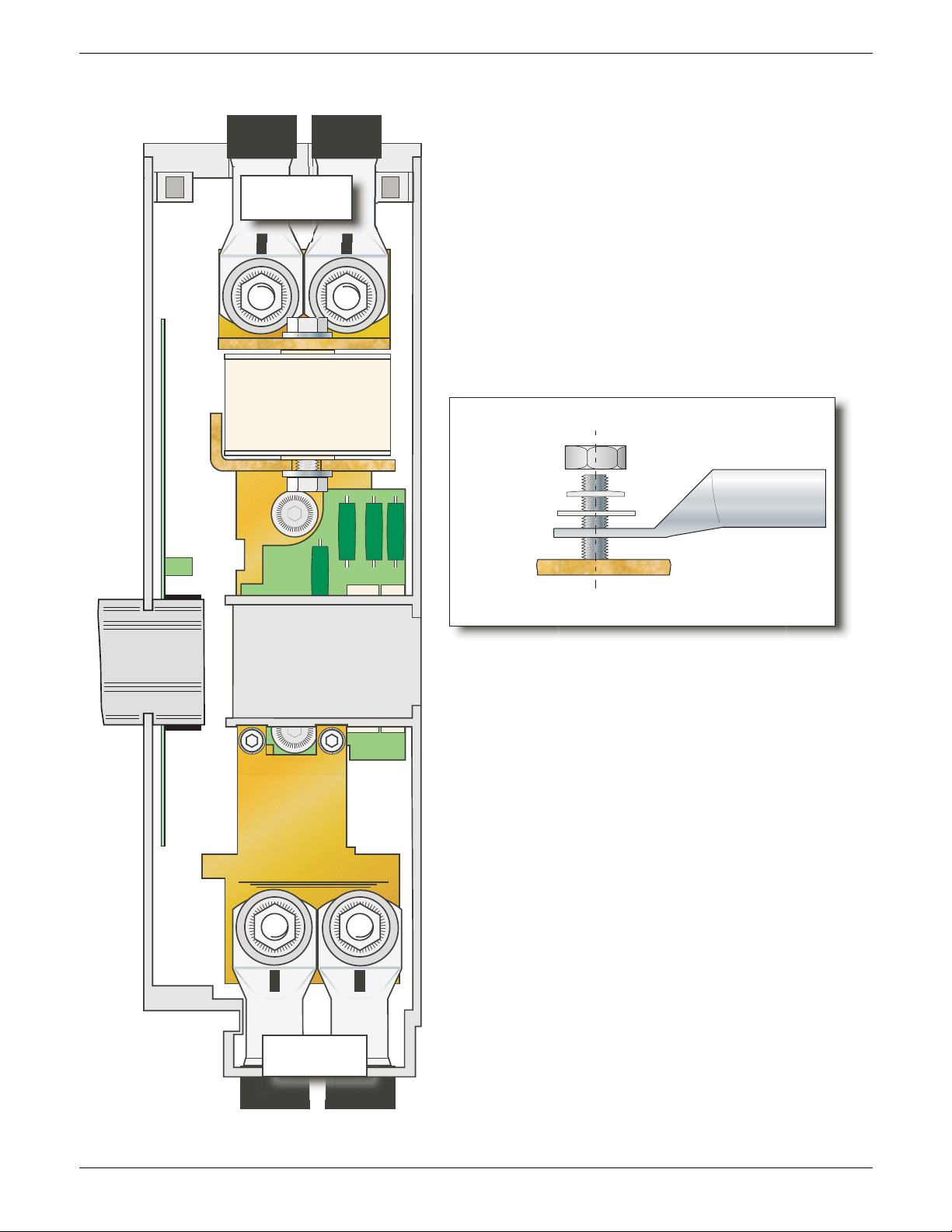
2.2.2 POWER MODULES (Cont.)
Supply
voltage
termination
Load
termination
Ribbon
cable (in)
Recommended torque = 30 Nm
Termination detail
Fuse
M12 Nut
(19mm A/F)
Spring washer
Flat washer
Ring terminal
Copper busbar
EPOWER CONTROLLER USER GUIDE
Figure 2.2.2f Line and Load termination (630A units)
Page 36 Issue 11 Dec 15
HA179769
Page 39
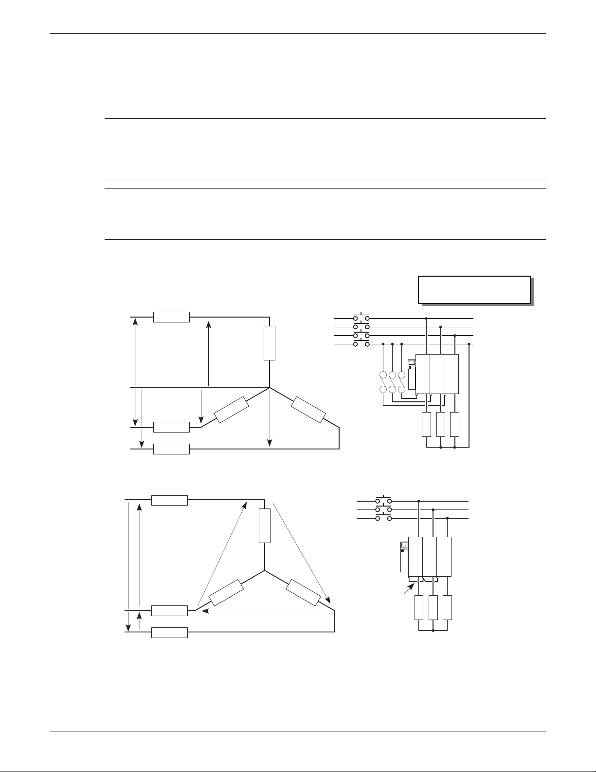
EPOWER CONTROLLER USER GUIDE
1/L1 3/L2 5/L3
2/T1 4/T2 6/T3
1/L1
3/L2
5/L3
2/T1
4/T2
6/T3
V
V3
V2
V
V3
V2
1/L1
3/L2
5/L3
2/T1
4/T2
6/T3
1/L1 3/L2 5/L3
2/T1 4/T2 6/T3
Fuse rating must be lower
than cable current rating
Phase
Phase
Phase
Phase 1
Phase 2
Phase 3
Neutral
EPower 1
EPower 2
EPower 3
Vline
Vline3
Star with neutral (4S)
Isolating
device
Fused
Neutral
reference
EPower 1
EPower 2
EPower 3
Load 1
Load 2
Load 3
Star without neutral (3S)
Phase
Phase
Phase
Phase 1
Phase 2
Phase 3
EPower 1
EPower 2
EPower 3
Vline
Vline3
Isolating
device
Reference inputs
connected
together
EPower 1
EPower 2
EPower 3
Load 1
Load 2
Load 3
Load 1 (Z)
Neutral
Vline2
L
o
a
d
2
(
Z
2
)
L
o
a
d
3
(
Z
3
)
Load 1 (Z)
L
o
a
d
2
(
Z
2
)
L
o
a
d
3
(
Z
3
)
2.2.2 POWER MODULES (Cont.)
The illustrations which make up figure 2.2.2g, below, show schematic and practical wiring arrangements for
a number of common three-phase configurations. Earthing and driver module wiring are omitted for the
sake of clarity. Fuses (where fitted) should have values compatible with the current carrying capacity of the
associated wiring. Appendix B contains a discussion of external feedback.
CAUTION
1. Neutral/phase reference connections (if applicable) must be located between any isolating
device and the relevant Power Module.
2. For single phase configurations, all Neutral reference connections must be individually fused.
Note: The figures below are intended only as theoretical examples. In order to comply with NEC
requirements, branch circuit protection must be incorporated by the user, upstream of the
equipment. Such protection is not shown in the figures below, for the sake of clarity. The installation,
in its entirety, must comply with all applicable local safety and emissions regulations.
THREE-PHASE STAR CONFIGURATIONS
Figure 2.2.2g Typical wiring schemes (Star)
HA179769
Issue 11 Dec 15 Page 37
Page 40
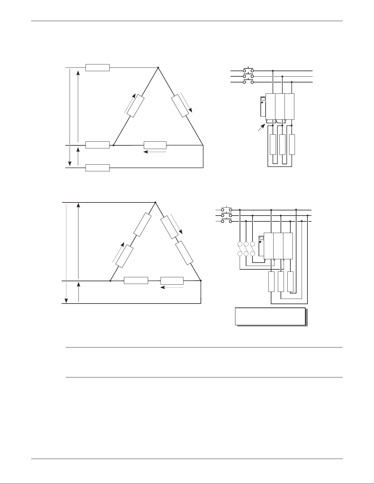
EPOWER CONTROLLER USER GUIDE
V3
φ1
φ2
φ3
φ2
φ3 φ1
V2
V
1/L1
3/L2
5/L3
2/T1
4/T2
6/T3
1/L1 3/L2 5/L3
2/T1 4/T2 6/T3
V
2
V
V
3
1/L1
3/L2
5/L3
2/T1
4/T2
6/T3
1/L1 3/L2 5/L3
2/T1 4/T2 6/T3
Phase
Phase
Phase
Phase 1
Phase 2
Phase 3
EPower 1
EPower 2
EPower 3
Vline
Vline3
Closed Delta (3D)
Isolating
device
Reference inputs
connected together
EPower 1
EPower 2
EPower 3
Load 1
Load 2
Load 3
Open Delta (6D)
Phase
Phase
Phase
Phase 1
Phase 2
Phase 3
EPower 2 Load 2
Vline2
Vline
Isolating
device
All reference
inputs fused
EPower 1
EPower 2
EPower 3
Load 1
Load 2
Load 3
Fuse rating must be lower
than cable current rating
L
o
a
d
1
Load 2
L
o
a
d
3
L
o
a
d
1
L
o
a
d
3
E
P
o
w
e
r
1
E
P
o
w
e
r
3
2.2.2 POWER MODULES (Cont.)
THREE-PHASE DELTA CONFIGURATIONS
Figure 2.2.2g (Cont.) Typical wiring schemes (Delta)
CAUTION
Neutral/phase reference connections (if applicable) must be located between any isolating device
and the relevant Power Module.
Page 38 Issue 11 Dec 15
HA179769
Page 41
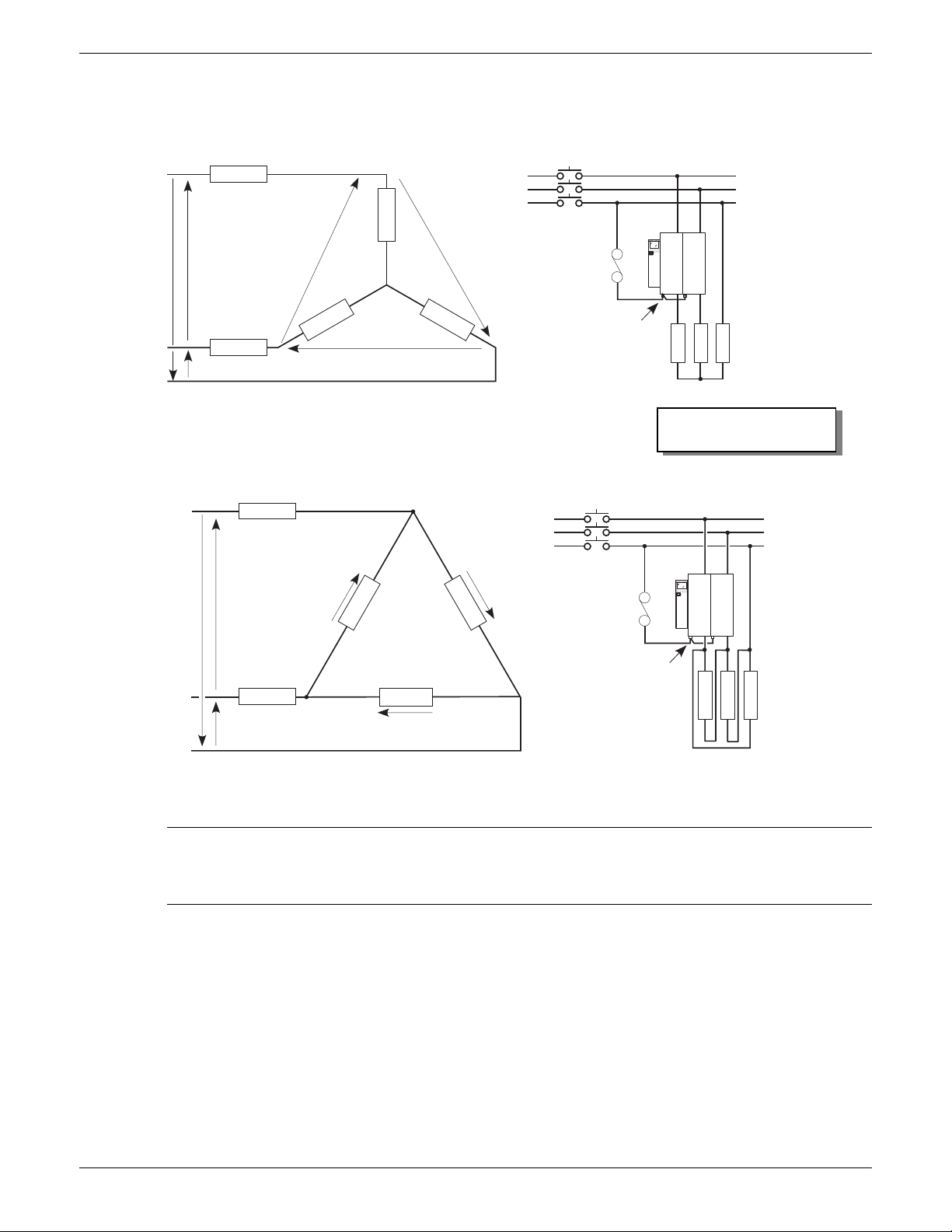
2.2.2 POWER MODULES (Cont.)
V
V2
V3
1/L1 3/L2
2/T1 4/T2
1/L1
3/L2
2/T1
4/T2
V
V2
V3
1/L1 3/L2
2/T1 4/T2
1/L1
3/L2
2/T1
4/T2
Phase
Phase
Phase
Phase 1
Phase 2
Phase 3
EPower 1
EPower 2
Vline
Vline3
Star (3S)
Isolating
device
Reference inputs
connected together
to phase 3.
EPower 1
EPower 2
Load 1
Load 2
Load 3
Delta (3D)
Phase
Phase
Phase
Phase 1
Phase 2
Phase 3
EPower 1
EPower 2
Load 2
Vline
Vline3
Isolating
device
Reference inputs
connected together to
phase 3.
EPower
EPower
Load 1
Load 2
Load 3
Fuse
Fuse
Vline2
Fuse rating must be lower
than cable current rating
Load 1
L
o
a
d
2
L
o
a
d
3
L
o
a
d
1
L
o
a
d
3
TWO-LEG CONFIGURATIONS
EPOWER CONTROLLER USER GUIDE
Figure 2.2.2g (Cont.) Typical wiring schemes (2-leg)
CAUTION
Neutral/phase reference connections (if applicable) must be located between any isolating device
and the relevant Power Module.
HA179769
Issue 11 Dec 15 Page 39
Page 42
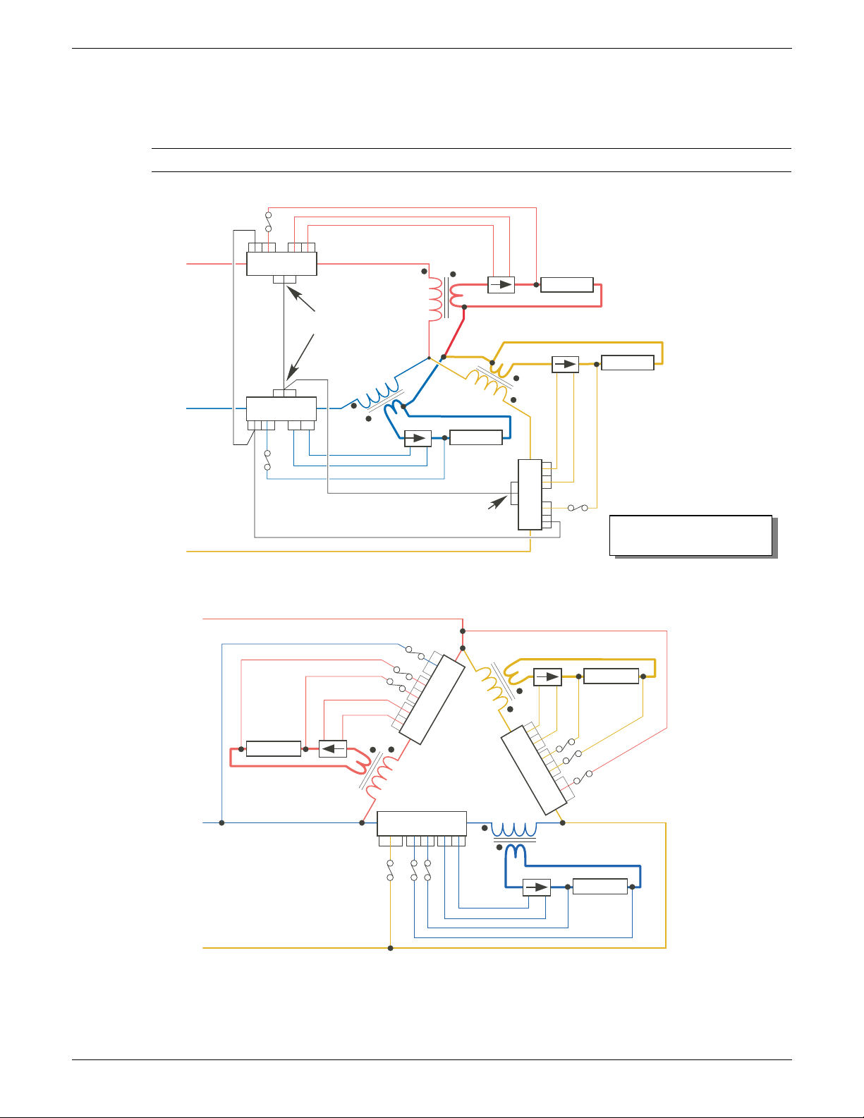
EPOWER CONTROLLER USER GUIDE
S1
S2
S1 S2
S1 S2
I1I2
V1V2
V1V2 I1I2
I1I2V1V2
EPower 1
V2V1
I2I1
V2 V1
I2 I1
EPower 3
V2
V1
I2I1
S1
S2
S1
S2
S1S2
Phase 1
Phase 2
Phase 3
Phase
Reference
EPower 1
EPower 2
Star without neutral (3S)
Phase
Reference
EPower 3
Load 1
Load 2
Load 3
Open Delta (6D)
Phase 1
Phase 2
Phase 3
2 phase reference
EPower 2
Load 2
Load 3
Load 2
3 phase
reference
1 phase
reference
Fuse rating must be lower
than cable current rating
2.2.2 POWER MODULES (Cont.)
THREE PHASE CONFIGURATIONS WITH EXTERNAL FEEDBACK
See for a discussion about external feedback, including more examples.
Note: The current transformer should be chosen such that its full-scale output is 5 amps.
Figure 2.2.2g (cont.) Typical 3-phase external feedback wiring
Page 40 Issue 11 Dec 15
HA179769
Page 43
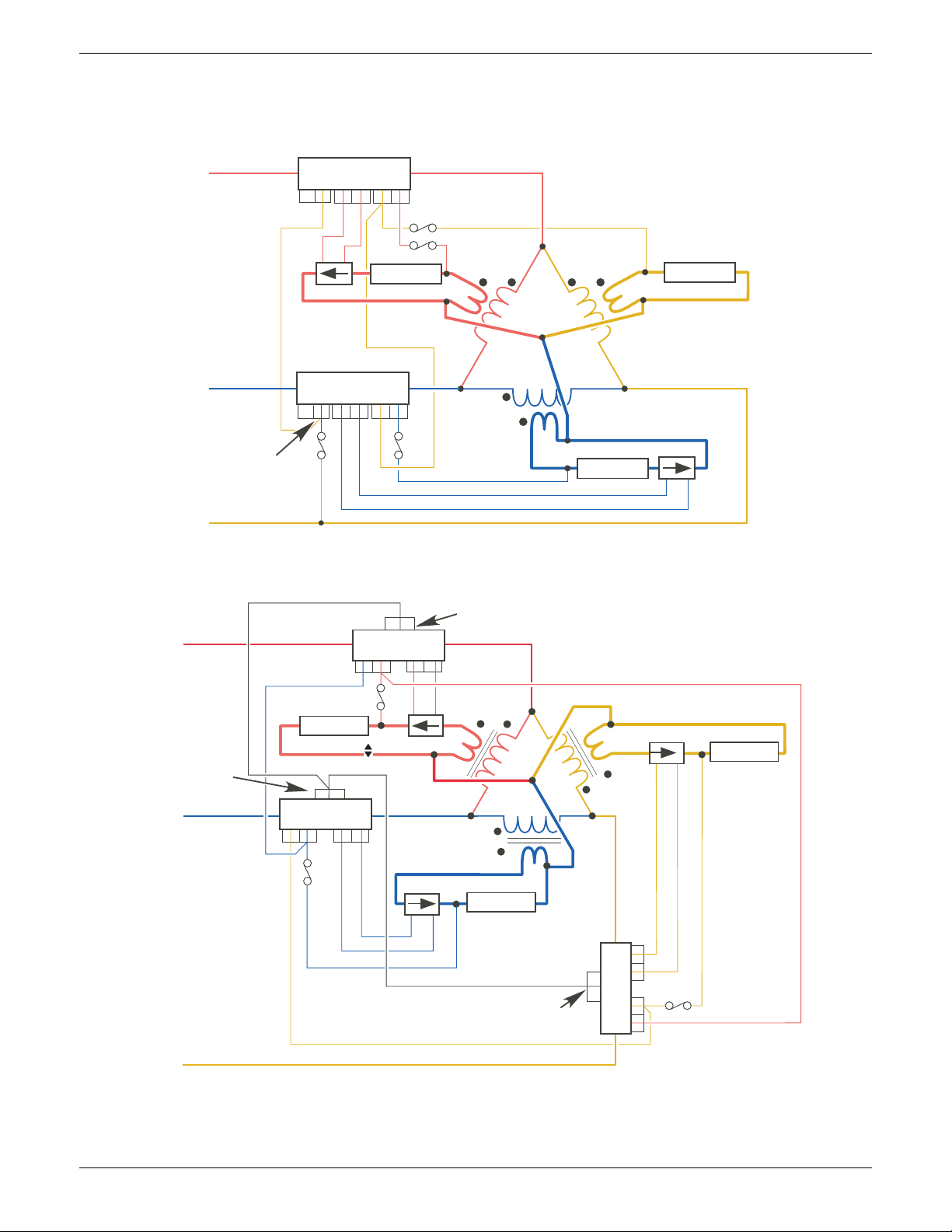
EPOWER CONTROLLER USER GUIDE
I1I2V1V2
S1S2
S1
S2
S1
S2
I1I2
V1V2
V1V2 I1I2
Phase
Phase
Phase 3
Phase
Reference
EPower 1
EPower 2
2-leg Delta (3D)
Load 1
Load 2
Load 3
Closed Delta (3D)
Phase 1
Phase 2
EPower 2
Load 1
Load 3
Load 2
Phase
Reference
Phase
Reference
EPower 1
Phase
Reference
EPower 3
Phase 3
2.2.2 POWER MODULES (Cont.)
THREE PHASE CONFIGURATIONS WITH EXTERNAL FEEDBACK (Cont.)
I1I2 V1V2
S1S2
Beacons
I1I2 V1V2
S1
S2
HA179769
Issue 11 Dec 15 Page 41
Figure 2.2.2g (cont.) Typical 3-phase external feedback wiring
Page 44
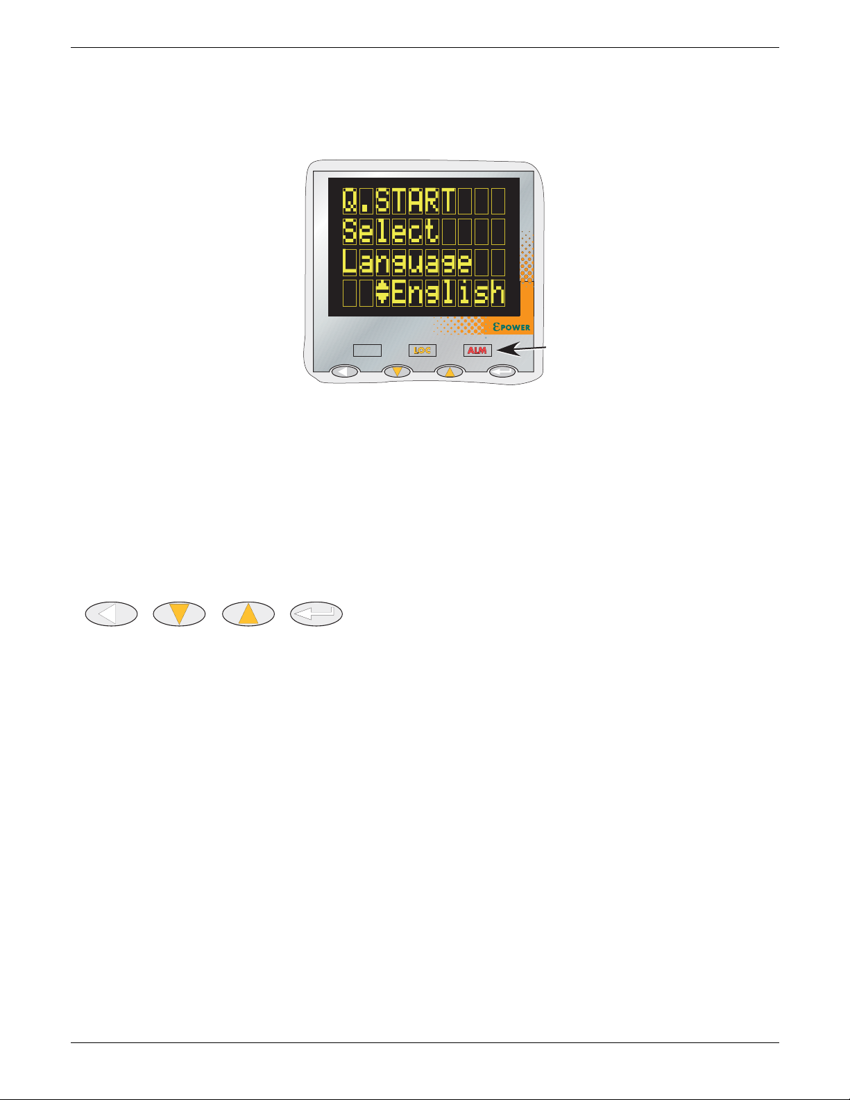
EPOWER CONTROLLER USER GUIDE
PWR
Return
Scroll
Down
Scroll
Up
Enter
3 OPERATOR INTERFACE
Located at the front of the Driver Module, the operator interface consists of a display, featuring four lines of
up to 10 characters each, four push-button switches and three LED ‘beacons’.
Figure 3 Operator interface
3.1 DISPLAY
As mentioned above, the display consists of four lines of characters, these characters being formed using a
seven-high, by five-wide dot matrix. This display, together with the four pushbuttons allows full operation
and configuration of the unit.
3.2 PUSHBUTTONS
The functions of the four pushbuttons below the display depend on whether the unit is in configuration
mode or in operating mode:
3.2.1 Configuration
Return Generally, this button reverses the last operation of the ‘Enter’ button
Scroll down/up Allows the user to scroll through the available menu items or values. The up/down
arrow symbol appears against menu items that can be edited.
Enter Goes to next menu item.
3.2.2 Operation
In operation, two pushbuttons may be operated simultaneously to carry out the following functions:
Scroll up + Scroll down Acknowledge alarms
Scroll up + Enter Toggle between ‘Local’ and ‘Remote’ operation.
Scroll down + Enter PLF adjustment request
3.2.3 Menu item value selection
Menu items are scrolled through using the enter key. Editing of the item’s value is carried out by scrolling
through the available choices, using the up and down scroll keys. Once the desired value is displayed, it will
become the selected value approximately two seconds after the final scroll key operation, this selection
being indicated by a single off/on flash of the desired value.
Page 42 Issue 11 Dec 15
HA179769
Page 45

EPOWER CONTROLLER USER GUIDE
PWR
3.3 BEACONS
There are three LED illuminated ‘beacons’ between the display area and the pushbuttons. For clarity, figure
3, above, shows the locations of these beacons in an enhanced way; on the real instrument, they are
‘invisible’ unless illuminated.
PWR ‘Power’. Illuminated green whilst power is applied to the unit. The Beacon flashes if any of
the associated power modules is not firing, or if the unit is in Standby (for any reason
other than that the unit is in ‘config’ mode).
LOC ‘Local’. Illuminated orange when setpoints are to be read from the operator interface or
from PC/iTools.
ALM ‘Alarm’. Illuminated red when one or more enabled alarms is active.
3.4 FRONT PANEL MESSAGES
A number of messages can appear at the display panel. These messages and their interpretations are listed
below. See section 10 for a more detailed description of some of these alarms.
3.4.1 Instrument events
Cold Start The instrument has been cold-started.
Conf Entry The instrument has been placed in configuration mode.
Conf Exit The instrument has been taken out of configuration mode.
GlobalAck A global acknowledgement of all safe latched alarms has been performed.
Power down The instrument has restarted after a power down.
QS Entry The Quick Start menu has been re-entered.
QS Exit The Quick Start menu has been left.
3.4.2 Indication alarms
LimitAct One or more limits are active in the control block
LoadOverI An over current alarm has become active in one or more Network blocks.
LMoverSch (Predictive Load Management over schedule). The actual power (Pr) is greater than the
requested shed power value (Ps) (detected in the PLM block).
PrcValTfr Process value transfer is active in one or more control blocks,
3.4.3 System alarms
FuseBlown One or more thyristor protection fuses is ruptured.
MainsFreq Mains Frequency is outside the acceptable range.
Missmains One or more supply phases is missing.
NetwDip One or more ‘network dip’ alarms has been detected.
OverTemp One or more ‘over temperature’ alarms has been detected.
PMod24V A power supply problem has been detected on the Driver Unit power board.
3.4.4 Process alarms
ChopOff One or more ‘Chop-off’ alarm has been detected.
ClosedLp One or more Control block ‘Closed Loop’ alarm has been detected.
InputBrk An ‘Input Break’ alarm has been detected in one or more Analogue input blocks.
MainVFault One or more ‘Mains Voltage Fault’ (over or under) has been detected.
OutFault An ‘Output short Circuit’ alarm has been detected in one or more Analogue output
blocks.
PLF One or more ‘Partial Load Failure’ alarm has been detected.
PLU One or more ‘Partial Load Unbalance’ alarm has been detected.
TLF One or more ‘Total Load failure’ alarm has been detected.
HA179769
Issue 11 Dec 15 Page 43
Page 46

EPOWER CONTROLLER USER GUIDE
3.4.5 Configuration errors
InvPAdata (Invalid parameter database). The non-volatile parameter database has become
corrupt and should not be relied upon.
InvWires (Invalid wiring table). The non-volatile storage of user (soft) wiring has become corrupt
and should not be relied upon.
3.4.6 Standby errors
PwrModRev (Power Module revision). One or more power units has an invalid revision number, or
its revision level is not compatible with the firmware version of the driver module.
HWDiffers The fitted hardware does not match the instrument configuration.
ErrDSP Error(s) reported by the Digital Signal Processor, during the instrument’s start-up self
test procedure.
Pwr1Ribbon A fault was detected in the power module 1 ribbon cable during the instrument’s start-
up self test procedure.
Pwr2(3)(4)Ribbon As above but for power module 2, 3 or 4.
3.4.7 Power module errors
Ph1(2)(3)(4)ComErr The phase 1, 2, 3 or 4 power module has attempted to communicate with the driver
module, and either the driver module or the power module (or both) has failed to
‘understand’ the communication commands/responses.
Ph1ComTout (Comms timeout). The phase 1, 2, 3 or 4 power module indicated that it wished to
report a fault to the driver module but the communications transaction was not
completed.
Ph2(3)(4)ComTout As for phase 1, above but for phase 2, 3 or 4.
Pwr1EEProm Header information in power module 1 non-volatile memory was found to be invalid at
the instrument’s start-up self test procedure.
Pwr2(3)(4)EEProm As for power module 1, above but for power module 2, 3 or 4.
Ph1(2)(3)(4)Wdog The phase 1, 2, 3 or 4 power module microprocessor has detected that its watchdog
timer has timed out. A reset has been performed and this has caused the power
module to report the fault.
3.4.8 General errors
Watchdog The driver module’s microprocessor has detected that its watchdog timer has timed
out, and has therefore performed a reset, causing the instrument to restart.
LogFault The event log could not be restored at start-up.
PWR1(2)(3)(4)cal The calibration data stored in the non-volatile memory of power module 1, 2, 3 or 4 is
invalid, and the default calibration will be used instead.
3.4.9 Reset errors
InvRamCsum (Invalid RAM checksum). Internal fault
DSPnoRSP (DSP no response). Internal fault.
DSP Wdog (DSP task watchdog). Internal fault.
3.4.10 Fatal errors
FuseConfig The driver module’s internal fuses are incorrectly configured.
ErrRestart An error has occurred that requires the instrument to be restarted.
HA179769
Page 44 Issue 11 Dec 15
Page 47
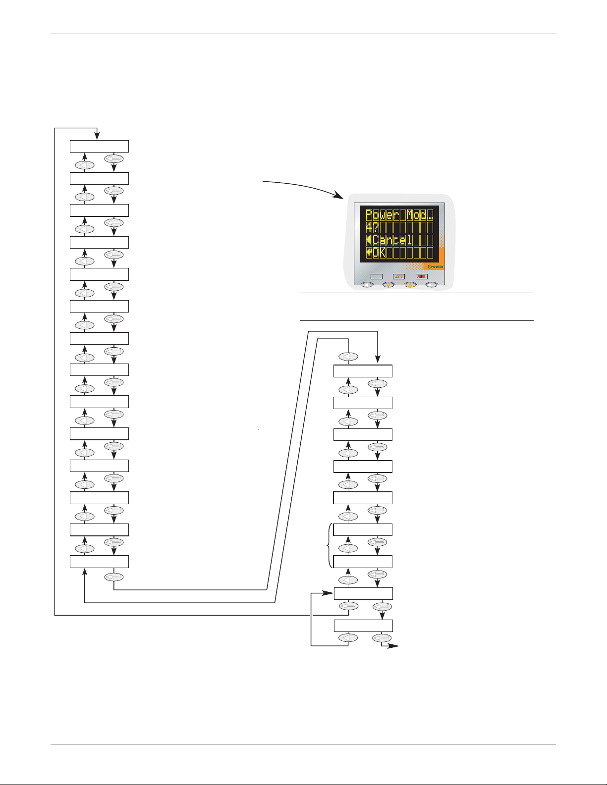
EPOWER CONTROLLER USER GUIDE
PWR
Use up/down scroll to select:
English, French, German, Italian
Select Language
Pow er Mod ul es
Nominal Current
Nominal Voltage
Network Type
Load Coupling
Load Type
Firing Mode
Feedback
Tra nsf er Mo de
Analog IP 1 Func
Analog IP 1 Type
Analog IP 2 Func
Analog IP 2 Type
Analog OP 1 Func
Analog OP 1 Type
Digital IP 2 func
Relay 1 func
Energy
Load Man Type
Load Man Addr
Finish
Finish Yes?
Use up/down scroll to select 0, 1, 2, 3 or 4
Change confirmation is required, as shown.
Use up/down scroll to select nominal current.
Maximum value = Current rating of power modules
Use up/down scroll to select nominal voltage
(see text for more details)
Use up/down scroll to select 1, 2, 3 or 4 phase. Available values depend on the number of power modules
selected.
Use up/down scroll to select:
3Star, 3Delta, 4Star, 6Delta
Use up/down scroll to select:
Resistive or Txformer (i.e. Transformer)
Use up/down scroll to select: None, Logic, Burst Var,
Burst fix, Half cycle, Ph. Angle
Use up/down scroll to select:
Open loop, V
2
, I2, Power, V
rms
, I
rms
Appears only if Feedback is not ‘Open Loop’
Use up/down scroll to select: None, I2 or I
rms
Use up/down scroll to select: Unused, Setpoint,
SP limit, I limit, V limit, P limit, Transfer
Appears only if IP Func is not ‘Unused’
Use up/down scroll to select:
0-10V, 1-5V, 2-10V, 0-5V, 0-20mA, 4-20mA
Use up/down scroll to select: Unused, Setpoint,
SP limit, I limit, V limit, P limit, Transfer
Appears only if IP Func is not ‘Unused’
Use up/down scroll to select: 0-10V, 1-5V,
2-10V, 0-5V, 0-20mA, 4-20mA
Use up/down scroll to select: Unused,
Power, Current, Voltage, Impedance
Appears only if OP Func is not ‘Unused’
Use up/down scroll to select: 0-10V,
1-5V, 2-10V, 0-5V, 0-20mA, 4-20mA
Use up/down scroll to select:
Unused, RemSP Sel, Alarm Ack
Use up/down scroll to select:
Unused, Any Alarm, NetwAlarm, Fuse Blown
Appears only if Energy Counter option enabled.
Use up/down keys to select Energy Counter on or off
Use up/down keys to select Load Management
type (see text)
Use up/down keys to set Load Management
address.
Use up/down scroll to select:
No, Yes
Confirm
Appear only if ‘Load
Management’ option
fitted
No Yes
Cancel OK
Note: Confirmation is required if the number of
power modules is edited
4 QUICKSTART
At first switch-on, the Driver Module enters the ‘QuickStart’ menu which allows the user to configure the
major parameters without having to enter the full configuration menu structure of the unit. Figure 4 shows
an overview of a typical Quickstart menu. The actual displayed menu items will vary according to the number
of options fitted.
HA179769
Figure 4 Typical Quickstart menu
Issue 11 Dec 15 Page 45
Page 48

EPOWER CONTROLLER USER GUIDE
Power Modules Network Type
0 0
11
2 1 or 2
3 1 or 3
4 1 or 2
4 QUICKSTART MENU (Cont.)
Notes:
1. If the unit has been fully configured at the factory, the Quickstart menu will be skipped, and the
unit will go into operation mode at first switch on.
2. Once quit, the Quickstart menu can be returned to at any time from the Engineer or
Configuration menus (described later in this document) by holding the ‘Return’ key operated for
approximately two seconds. If values have been changed ‘outside’ the Quickstart menu, these
values are displayed as ‘---’ on re-entry to the Quickstart menu.
4.1 QUICKSTART MENU PARAMETERS
Language Initially, English, French, German and Italian may be selected. Other languages may be
added during the lifetime of this issue of the manual. Once confirmed (single blink
after approximately two seconds), then all further displays appear in the selected
language.
Power Modules Select the number of power modules between 0 and 4 that the driver module is to
control. The number of phases offered (in Network type, below) depends on this value.
Editing this value causes a confirmation screen to appear. ‘OK’ confirms the change.
Nominal Current A value, normally between the maximum current the Power Modules are each able
safely to sustain and a quarter of this value. Thus, for a 400 Amp unit, any nominal
current value between 100 and 400 may be selected. (Lower values are not
recommended as in such cases, the resulting accuracy and linearity are not guaranteed
to be within specification.)
Nominal Voltage A value between the maximum permanent supply voltage (+10%) to the modules, and
a quarter of this value. Available values are 100, 110, 115, 120, 127, 200, 208, 220, 230,
240, 277, 380, 400, 415, 440, 460, 480, 500, 575 and 600.
Network Type Allows the user to select 1, 2 or 3 phases depending on the
selection made in ‘Power Modules’, above. The table shows the
choices.
Load Coupling For Network Type entries other than single phase:
2 phase: allows 3 Star or 3 Delta to be selected
3 phase: allows 3 Star, 3 Delta, 4 Star or 6 Delta to be selected.
Load Type Allows ‘Resistive’ or ‘Txformer’ (transformer) to be selected as the type of load. If
Txformer is selected, this modifies the start up procedure to limit the inrush current.
Firing Mode Select from ‘Logic’, ‘BurstVar’, ‘BurstFix’, ‘HalfCycle’ or ‘Ph.Angle’.
Feedback
Transfer Mode
Allows the user to choose open Loop, V
If Feedback is set to any value other than ‘Open Loop’, ‘None’, ‘I
selected as transfer mode. If Feedback is set to ‘Open Loop’, the Transfer Mode page
does not appear.
Analog IP1 Func Selects the Analogue input 1 function as ‘Unused’, ‘Setpoint’, ‘SP limit’, ‘I limit’, ‘V limit’,
‘P limit’ (power limit) or ‘Transfer’. Allows (for example) a potentiometer to be
connected to Analogue input 1, so that setpoint can be dynamically varied.
Analog IP 1 Type Allows the user to select the analogue input type as 0 to 10V, 1 to 5V, 2 to 10V, 0 to 5V,
0 to 20mA, 4 to 20mA. This menu item does not appear if ‘Unused’ is selected in IP1
Func (above).
Analog IP 2 Func As for Analog IP 1 Func, except ‘Setpoint’ does not appear if it has already been
selected as Analog IP 1 type
Analog IP 2 Type As for Analog IP 1 type
Analog OP 1
Func
Analog OP 1
Ty pe
Allows the user to select ‘Unused’. ‘Power’, ‘Current’, ‘Voltage’ or ‘Impedance’ to be
selected as output type.
Allows the user to select the analogue output type as 0 to 10V, 1 to 5V, 2 to 10V, 0 to 5V,
0 to 20mA, 4 to 20mA. This menu item does not appear if ‘Unused’ is selected in OP1
Func (above).
Digital IP2 Func Select Digital input 2 function as ‘Unused’, ‘RemSP Sel’ (Remote setpoint select) or
‘Ala rm Ack’
Relay 1 Func Allows the function of Relay 1 to be set as ’Unused’, ‘Any Alarm’, ‘NetwAlarm’, or ‘Fuse
Blown’.
2
, I2, Power, Vrms or Irms.
2
’ or ‘Irms’ can be
Page 46 Issue 11 Dec 15
HA179769
Page 49

EPOWER CONTROLLER USER GUIDE
4.1 QUICKSTART PARAMETERS (Cont.)
Relay 1 Func Allows the function of Relay 1 to be set as ’Unused’, ‘Any Alarm’, ‘NetwAlarm’, or ‘Fuse
Blown’.
Energy Appears only if one or more Energy counter blocks (section 6.10) are included in the
configuration. Allows energy counters to be enabled and disabled.
Load Man Type Appears only if the Predictive Load Management option is fitted. Allows the user to
select one of LMNo (disabled), Sharing, IncrT1, IncrT2, RotIncr, Distrib, DistIncr,
RotDisInc.
See section 9 for more details.
Load Man Address Appears only if the Predictive Load Management option is fitted. Allows the user to
enter a Predictive Load Management address.
Finish Select ‘No’ to return to the top of the Quickstart menu, or ‘Yes’ to enter the User
menu, after confirmation. (See also note below.)
Note: The ‘Finish’ item might not appear if an inconsistent or incomplete configuration is entered. In
such a case, the ‘Language’ selection page at the top of the menu re-appears.
HA179769
Issue 11 Dec 15 Page 47
Page 50
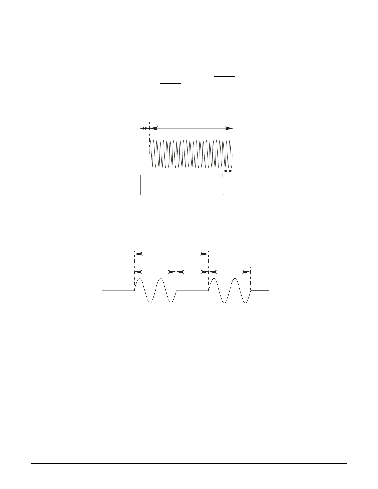
EPOWER CONTROLLER USER GUIDE
Power on-off delay = two or three mains
periods depending on where in the mains
cycle the logic output changes state.
Power applied
Logic output from controller
Power applied
Tcyc = Ton + Toff
Tc yc
Power applied
To n To ff To n
4.2 SOME DEFINITIONS
4.2.1 Firing modes
LOGIC
Power switches on, two or three zero crossings of the supply voltage
switches off wo or three zero crossings of current
after the logic input switches off. For resistive loads, voltage
and current cross zero simultaneously. With inductive loads, a phase difference exists between the voltage
and current, meaning that they cross zero at different times. The size of the phase difference increases with
increasing inductance.
after the logic input switches on. Power
Figure 4.2.1a Logic firing mode
BURST FIXED FIRING
This means that there is a fixed ‘cycle time’ equal to an integer number of supply voltage cycles as set up in
the Modulator menu. Power is controlled by varying the ratio between the on period and the off period
within this cycle time (figure 4.2.1b).
Figure 4.2.1b Burst Fixed mode
Page 48 Issue 11 Dec 15
HA179769
Page 51
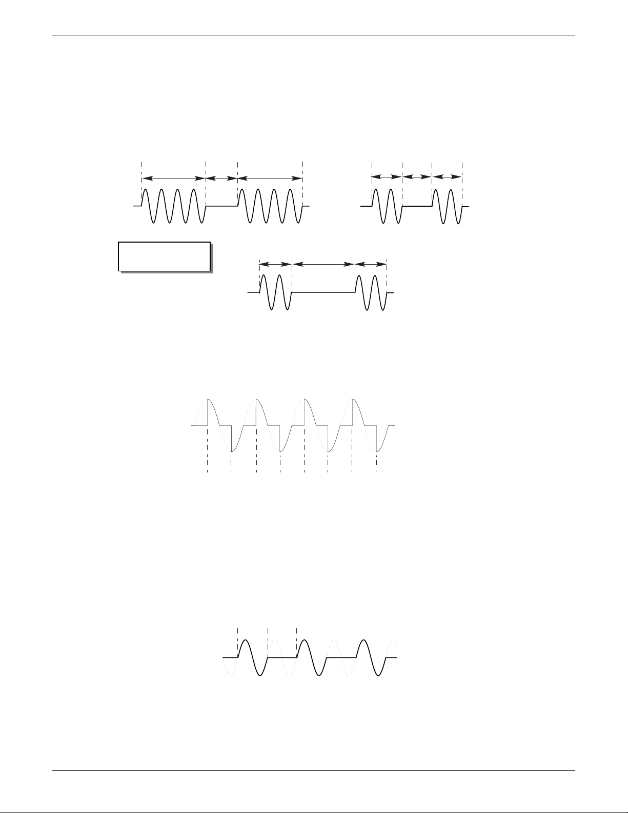
EPOWER CONTROLLER USER GUIDE
Toff = 2 x Min on = 33.3% duty cycle
To n
To n
To ff
To ffTo n To n
To ffTo n To n
Power applied
Power applied
Pow er
applied
Pow er
applied
Power applied
Pow er a pplied
Min on
Min off
Min offMin on Min on
Toff = 1/2 Min on = 66.7% duty cycle
Toff = Min on = 50% duty cycle
Min On = Min Off =
2 for these examples
On
50% shown.
Power is proportional to area under curve
On On On On On On On
For 50% duty cycle Tn = Toff = 2 half cycles
To n To ff
4.2.1 FIRING MODES (Cont.)
BURST VARIABLE FIRING
Burst Firing Variable is the preferred mode for temperature control. Between 0 and 50% of setpoint, the on
time is the ‘Min on’ time set in the modulator menu and the off time is varied to achieve control. Between
50% and 100%, the off time is the value set for ‘Min on’ and power is controlled by varying the number of on
cycles.
Figure 4.2.1c Burst variable firing
PHASE ANGLE CONTROL
This mode of firing controls power by varying the amount of each cycle which is applied to the load, by
switching the controlling thyristor on part-way through the cycle. Figure 4.2.1d shows an example for 50%
power.
Figure 4.2.1d Phase angle mode
HALF CYCLE MODE
Burst mode firing with a single firing (or non-firing) cycle is known as ‘Single cycle’ mode. In order to reduce
power fluctuations during firing time, Intelligent half-cycle mode uses half cycles as firing/non-firing periods.
Positive and negative going cycles are evened out, to ensure that no dc component arises. The following
examples describe half-cycle mode for 50%, 33% and 66% duty cycles.
50% DUTY CYCLE
The firing and non-firing time corresponds to a single supply cycle (figure 4.2.1e).
Figure 4.2.1e Half cycle mode: 50% duty cycle
HA179769
Issue 11 Dec 15 Page 49
Page 52
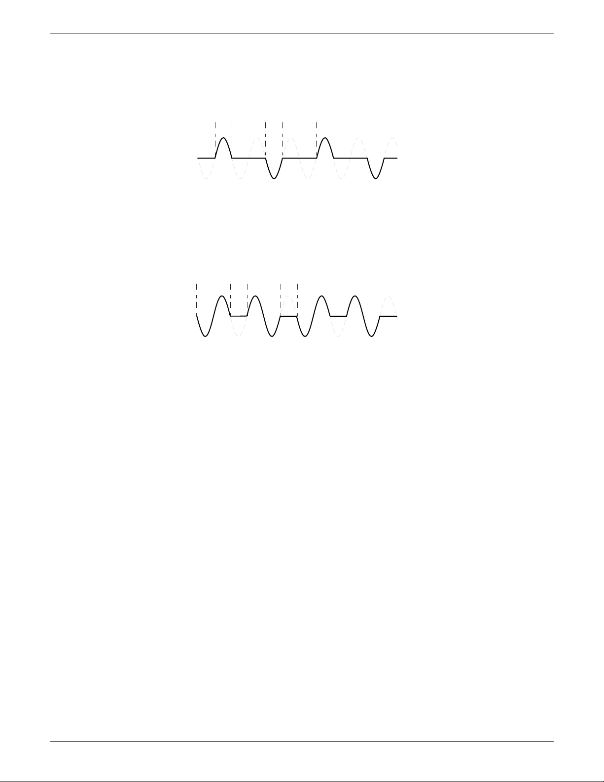
EPOWER CONTROLLER USER GUIDE
For 33% duty cycle
Ton = 1 half cycle; Toff = 2 half cycles
To n TonTo ff To ff
For 66% duty cycle
Ton = 2 half cycles; Toff = 1 half cycle
To n TonTof f
To ff
4.2.1 FIRING MODES (Cont.)
33% DUTY CYCLE
For duty cycles less than 50%, the firing time is one half-cycle. For a 33% duty cycle, firing time is one half
cycle; the non-firing time is two half-cycles (figure 4.2.1f).
Figure 4.2.1f Half cycle mode: 33% duty cycle
66% DUTY CYCLE
For duty cycles of greater than 50%, the non-firing time is one half-cycle. For 66% duty cycle, the firing time
is two half cycles; the non-firing time is one half cycle (figure 4.2.1g).
Figure 4.2.1g Half cycle mode: 66% duty cycle
4.2.2 Feedback type
All feedback types (except ‘Open Loop’) are based on real-time measurement of electrical parameters that
are normalised to their equivalent Nominal values. Thus V
normalised to the square of Nominal Voltage and ‘P’ is normalised to the product of Nominal Voltage and
Nominal Current.
2
V
Feedback is directly proportional to the square of the RMS voltage measured across
the load. For two- or three-phase systems, feedback is proportional to the average of
the squares of the individual phase-to-phase or phase-to-Neutral RMS voltage across
each load.
Power Feedback is directly proportional to the total true power delivered to the load network.
2
I
Feedback is directly proportional to the square of the RMS current through the load.
For two- or three-phase systems, feedback is proportional to the average of the
squares of the individual RMS load currents.
V
rms
Feedback is directly proportional to the RMS voltage measured across the load or, for
multi-phase systems, to the average of the individual phase-to-phase or phase-toneutral RMS load voltages.
I
Feedback is directly proportional to the RMS current through the load or, for multi-
rms
phase systems, to the average of the individual RMS load currents.
Open loop No measurement feedback. The thyristor firing angle in Phase angle mode, or the duty
cycle in burst-firing mode, are proportional to the setpoint.
is normalised to Nominal Voltage; V2 is
RMS
HA179769
Page 50 Issue 11 Dec 15
Page 53
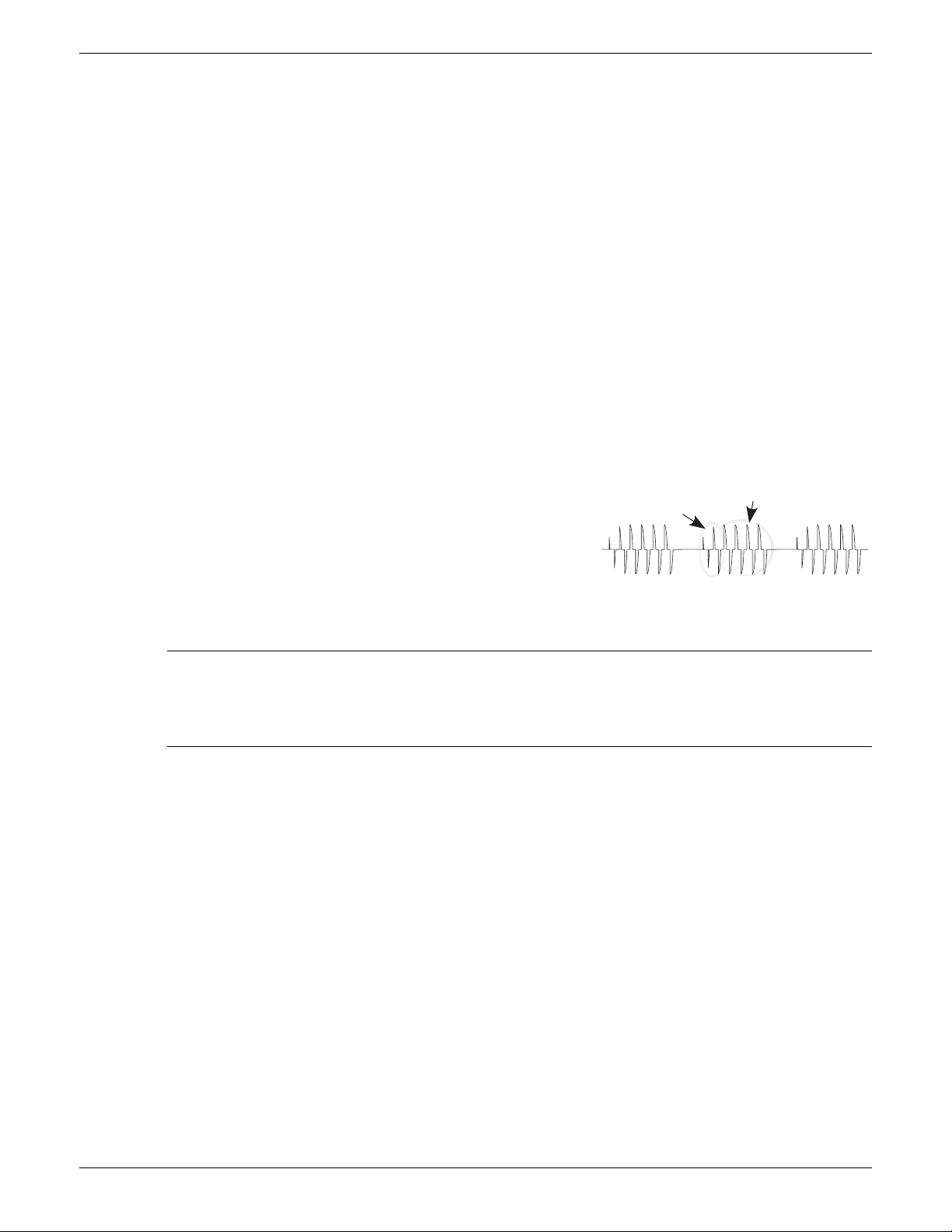
EPOWER CONTROLLER USER GUIDE
Limiting
(gradually reducing)
Target phase angle
4.2.3 Transfer Mode
The control system can use automatic transfer of certain feedback parameters. For example with loads with
very low cold resistance, I
warm up, Power feedback should be used; the control program can be configured to change feedback
mode automatically.
The Transfer mode can be selected as I
None No feedback parameter transfer to the control program
2
I
Selects transfer mode: I2 to the selected Feedback Mode (above).
I
rms
2
feedback should be used to limit inrush current, but once the load has started to
2
to P or I
Selects transfer mode: I
RMS
to P as appropriate to the type of load being controlled
rms
to the selected Feedback Mode (above).
4.2.4 Limitation features
In order, for example, to prevent potentially damaging inrush currents, it is possible to set a value for power
or Current squared which is not to be exceeded. This limiting is implemented using phase angle reduction,
duty cycle reduction or ‘chop off’, depending on the type of control (e.g. phase angle, burst firing). For loads
exhibiting a low impedance at low temperatures but a higher impedance at working temperature, the
current drawn reduces as the load warms, and limiting gradually becomes unnecessary.
Section 6.7.3 describes the configuration parameters which allow the user to enter a Process Variable (PV)
and a setpoint (SP) for each phase, where the PV is the value to be limited (e.g. I
the PV must not exceed.
FIRING ANGLE LIMITING
For phase angle control, limiting is achieved by reducing the firing
angle on each half mains cycle such that the limit value of the
relevant parameter is not exceeded. As limiting is reduced so the
phase angle tends to its target value.
2
) and the SP is the value that
DUTY CYCLE LIMITING
For Burst Firing only, limiting reduces the ‘On’ state of the burst firing driving the load. Load current, voltage
and active power are calculated over the period of each (Ton + Toff) period.
CAUTION
When applied to load current, duty cycle limiting does not limit the peak current value, and under
some circumstances this may allow an overheating hazard in the load and/or Power Module to
develop.
CHOP OFF
This is a limiting technique which detects an over-current alarm state and stops further thyristor firing for the
duration of that alarm state. All the relevant parameters are to be found in the Network Setup menu
(section 6.20.2).
There are two alarms which may trigger Chop Off, as follows:
1. The alarm is active when ChopOff1Threshold is exceeded for more than five seconds. This threshold
can be set to any value between 100% and 150% inclusive, of the unit’s nominal current (INominal).
2. The alarm is active if ChopOff2Threshold is exceeded more than a specified number of times (Number
Chop Off)) within a specified time period (Window Chop Off). ChopOff2Threshold is adjustable
between 100% and 350% inclusive, of Inominal; Number Chop Off can be selected to any value
between 1 and 16 inclusive; Window Chop Off can be set to any value between 1 and 65535 seconds
(approximately 18 hours 12 mins.).
Each time the threshold is exceeded, the unit stops firing, raises a chop off condition alarm, then after
100ms, restarts using an up-going safety ramp. The condition alarm is cleared if the unit successfully
restarts. If the alarm is raised more than the specified number of times within the specified window,
then the Chop Off alarm is set and the unit stops firing. Firing is not resumed until the operator
acknowledges the Chop Off alarm.
HA179769
Issue 11 Dec 15 Page 51
Page 54
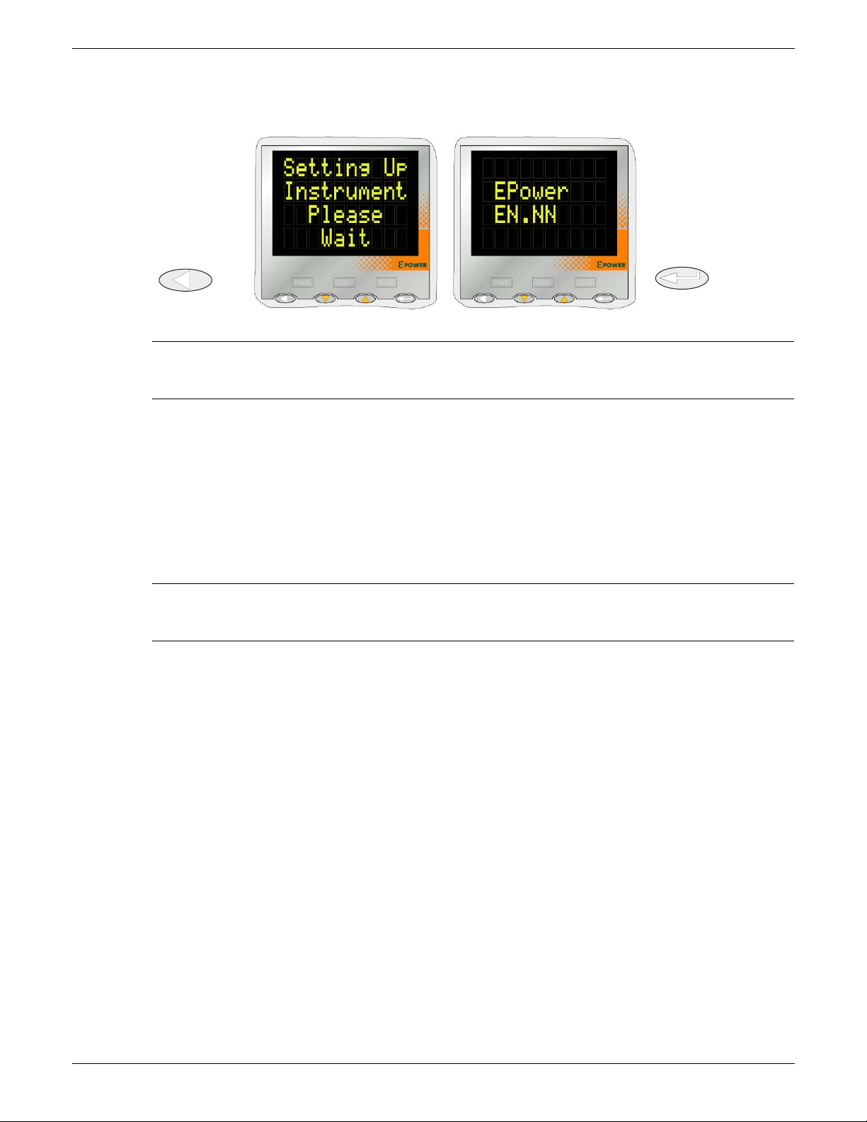
EPOWER CONTROLLER USER GUIDE
EN.NN = software
revision level
Enter keyReturn key
5 OPERATOR MENU
At power up or after quitting the Quickstart menu, the unit initialises itself (figure 5) and then enters the first
summary page of the Operator menu (figure 5.2).
Figure 5 Initialisation screens
Note: If any faults are detected during initialisation (e.g. supply voltage missing), then error
messages appear on the display screen. The up and down arrow keys must be operated
simultaneously to acknowledge each alarm in turn, before any further operations can take place.
5.1 SUMMARY PAGES
Each summary page displays the voltage, current and power status described below calculated over the
mains period when in Phase Angle mode or over the Modulation Period when in Burst Mode. The user may
also edit the local setpoint from the summary pages. Where more than one, single phase unit is being
driven, the parameter names have a numeric suffix (e.g. V2) to indicate which phase is being displayed. The
enter key can be used to scroll through the available phases.
The Return key can be operated briefly to access the top level operator menu, which contains all summary
pages and Alarm and Event Log entries. (Operation of the Return key for an extended interval calls the
Access page - see section 6.3)
Notes:
1. A suffix ‘n’ below represents the number of the network currently being displayed.
2. ‘LSP’ is replaced in the display by ‘RSP’ for remote working.
5.1.1 Single phase summary page
Vn The RMS load voltage measurement for network ‘n’.
In The RMS load current measurement for network ‘n’.
Pn The true power delivered to network ‘n’.
LSPn The local setpoint value for network ‘n’ - see also Note 2 above.
5.1.2 Two or three phase summary page
Vavg The average RMS load voltage over all three loads.
Iavg The average RMS load current over all three loads.
P The true power delivered to the load network.
LSP The local setpoint value - see also Note 2 above.
5.1.3 Two by two phase summary page
This is a mode of operation whereby a single four-power-module unit can control two independent, threephase networks.
Vavn The RMS load voltage averaged over all three loads for network ‘n’.
Iavn The RMS load current averaged over all three loads for network ‘n’.
Pn The true power delivered to load network ‘n’.
LSPn The local setpoint value for network ‘n’ - see also Note 2 above.
HA179769
Page 52 Issue 11 Dec 15
Page 55
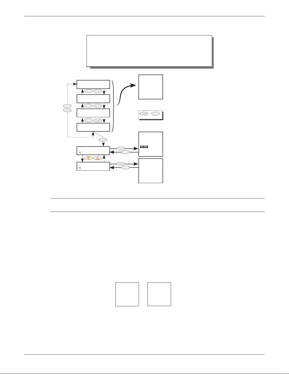
EPOWER CONTROLLER USER GUIDE
1st Summary page appears:
1. After quitting the Quickstart menu.
2. On power up if the unit was left in Access level 1
(operator) or 2 (Engineer) at power down. (If powered off in Config mode, it restarts in Config mode.)
Use the ‘Enter’ key to scroll through summary pages.
The number of summary pages depends on the number (n) of separate power networks in the system.
n = 1, 2, 3 or 4 according to which Summary page is
being displayed.
n is not present if there is only one summary page.
Hold the Enter key continuously operated to return to
the summary pages.
Hold the Return key continuously operated to call the
Access (Goto) page.
Hold operated
for 2 secs min.
Enter Return
Use the Enter key to scroll through alarms, acknowledging them as required.
Hold the Enter key continuously operated to return to
the summary pages.
Hold the Return key continuously operated to call the
Access (Goto) page.
Use the Enter or up/down keys to scroll through the
event log.
Hold the Enter key continuously operated to return to
the summary pages.
Hold the Return key continuously operated to call the
Access (Goto) page.
Summary Page 1
Summary Page 3
Summary Page 2
Summary Page 4
USER Menu
USER Menu
Alarms
EventLog
Alm summry
Miss Mains
Please wait
Event Log
Event 1
ErrStandby
HwDiffers
Vn 248.9V
In 120.3A
Pn 29943W
LSPn 55%
EventLog
EventNN
Event Type
Event ID
EventLog
Event30
Instrument
Conf Exit
General
Typical example
5.2 TOP LEVEL OPERATOR (USER) MENU
Figure 5.2 User menu overview
Note: The summary page is displayed at switch on only if the unit has been configured, either via the
Quickstart menu, or at the factory. Otherwise, at first switch on, the Quickstart menu is entered.
Summary pages are discussed in section 5.1, above.
5.2.1 Alarm Summary pages
This page contains a list of currently active alarms, together with a group of four flashing bell symbols if the
alarm is unacknowledged. The ‘Enter’ key is used to scroll through the list, and the up/down arrow keys are
operated, simultaneously, to acknowledge each alarm, as required.
5.2.2 Event Log
This is a list of up to 40 event items where Event 1 is the latest. As shown in the figure below, Event number,
Event Type and Actual Event (known as ‘Event ID’) appear on the screen.
Event Types and Event IDs are given in table 5.2.2.
HA179769
Issue 11 Dec 15 Page 53
Page 56
5.2.2 EVENT LOG (Cont.)
‘n’ = 1, 2, 3 or 4
Event Type Event ID
Config error
DSP Error
Fatal error
General error
Indication Alarm Network ‘n’ Active
Indication Alarm Network ‘n’ Inactive
Indication Alarm Network ‘n’
Acknowledged
Instrument event
Network ‘n’ error
Power Module ‘n’ error
Process Alarm External ‘n’ Active
Process Alarm External ‘n’ Inactive
Process Alarm External ‘n’ Acknowledged
Process Alarm Network ‘n’ Active
Process Alarm Network ‘n’ Inactive
Process Alarm Network ‘n’ Acknowledged
Restart Error
Standby Error
System Alarm Network ‘n’ Active
System Alarm Network ‘n’ Inactive
System Alarm Network ‘n’ Acknowledged
EPOWER CONTROLLER USER GUIDE
E
XTERNAL PROCESS ALARMS
Deviation Band
Deviation High
Deviation Low
High
Low
F
ATAL ERRORS
Internal Fuse configuration
Restart Failure
C
ONFIG ERRORS
Invalid parameter database
Invalid wiring table
I
NDICATION ALARMS
Limit active
Load over current
Load Management over schedule
Process Value transfer
G
ENERAL ERRORS
Processor watchdog
Event Log fault
Power Module ‘n’ Calibration
I
NSTRUMENT EVENTS
Cold start
Config entry
Config exit
Global Acknowledge
Power down
Quickstart entry
Quickstart exit
N
ETWORK ERRORS
Phase ‘n’ power module Comms
err
Phase ‘n’ power module Timeout
Phase ‘n’ power module watchdog
P
OWER MODULE POST ERRORS
Comms error
Comms timeout
Fuse blown
Power rail fail
Watchdog
P
ROCESS ALARMS
Chop Off
Closed loop
Main voltage fault
Output short circuit
Partial load fault
Partial load unbalance
Temperature pre-alarm
Total Load Failure
R
ESET ERRORS
Invalid RAM checksum
DSP no response
DSP task Watchdog
S
TANDBY ERRORS
Invalid Power Module
Revision
Hardware mismatch
Power Module ‘n’ Ribbon
Fault
S
YSTEM ALARMS
Fuse Blown
Mains Frequency Fault
Missing mains
NetworkDip
Over Temperature
Pow er M odule 24V fau lt
Thyristor Open circuit
Thyristor Short circuit
Table 5.2.2 Event types and IDs
Notes:
1. Event ID ‘Fuse blown’ may appear in association with either Event Type ‘System Alarm Network
‘n’’ or Event Type ‘Power module ‘n’ Error’.
2. Event ID ‘Watchdog’ appears in association with Event Type ‘General error’ and indicates that the
microprocessor in the Driver Module has performed a watchdog reset.
3. Event ID ‘Watchdog fault’ appears with Event Type ‘Power Module ‘n’ Error’ and indicates that the
relevant Power Module PIC microprocessor has performed a watchdog reset.
5.2.3 Strategy Standby mode
For SCADA systems, in order to determine Standby mode, the user should use bit 8 of the Faultdet.Strategy-
Status parameter, not the Instrument.Mode parameter.
This is because Instrument Mode reflects user selection, not error states such as Hardware Mismatch.
HA179769
Page 54 Issue 11 Dec 15
Page 57
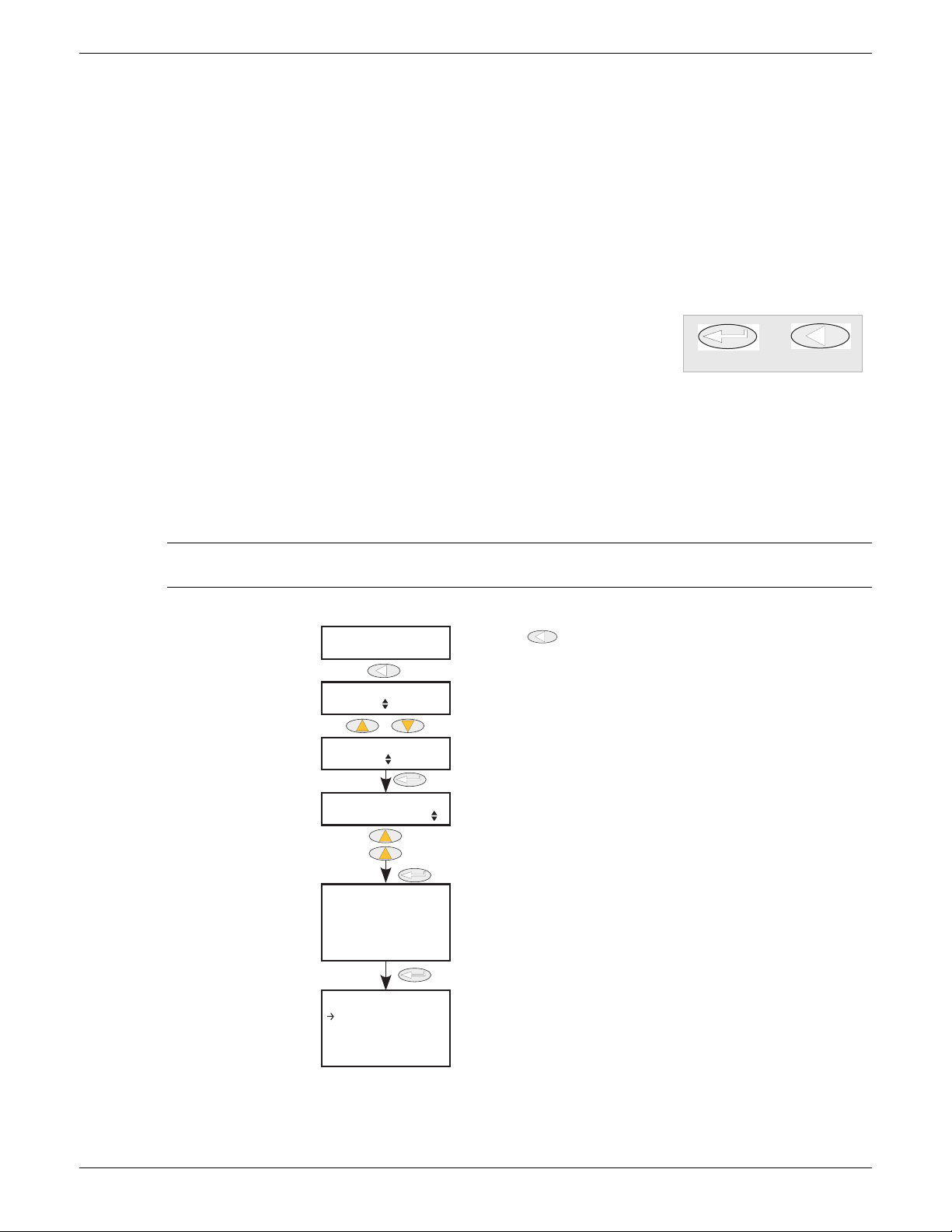
EPOWER CONTROLLER USER GUIDE
Enter key
Return key
Operate ‘Return’ [rtn key] repeatedly until no further changes occur,
then hold continuously operated until the access page appears.
Display depends on existing access level.
Use up/down arrow key to select Engineer.
Once selected, wait a few seconds or operate
the ‘Enter’ key for pass code page.
Hold 4 to 5 secs
Wait or
Code =1
Code =2
Default code = 2, but this may be edited in
the Configuration menu
Summary page
Hold ‘Enter’ operated until first engineer level
menu page appears
Wait or
Any Menu
Access Goto
Operator
V1 248.9
I1 120.3A
P1 29943w
LSP1 55%
Access Goto
Engineer
Access Pass code
ENG
Access
AnalogIP
AnalogOP
6 ENGINEER AND CONFIGURATION LEVEL MENUS
These two menu sets are mostly identical, displaying the unit’s parameters in a number of sub-menus. As the
Engineer level menu is accessible whilst the Driver Module is on-line to the power module(s), the majority of
the displayed items are Read Only (i.e. they can be viewed, but not edited), although some non-critical items
can be changed.
Full configuration may be carried out from the Configuration level menus, which (apart from the access
menu) contain the same parameters as the equivalent Engineering level menus. It is normally
recommended, however, that configuration be carried out from a pc running iTools configuration software.
In either case, the unit goes off-line as soon as Configuration mode is entered.
6.1 ACCESS TO THE ENGINEER AND CONFIGURATION MENUS
6.1.1 Engineer level menu
The Engineer level menu is entered as follows (figure 6.1.1):
1. Operate the return key repeatedly, until no further changes occur,
then hold the Return key continuously operated until the ‘Access’
‘Goto’ display appears.
2. Use the up or down arrow key until ‘Engineer’ appears.
3. Either wait for a few seconds or operate the Enter key.
4. Use the up or down arrow key to change the code to the Engineer level code (factory default = 2, but
reconfigurable in the CONFIG level menu)
5. Either wait for a few seconds or operate the Enter key to display the first Summary Page. Press and hold
the Enter key until the first page of the top level Engineer menu appears.
Note: when entering from configuration level no password is required. Once Engineer level has
been selected, the unit restarts in the Engineer top level menu
HA179769
Issue 11 Dec 15 Page 55
Figure 6.1.1 Access to the Engineer level menu
0
Page 58
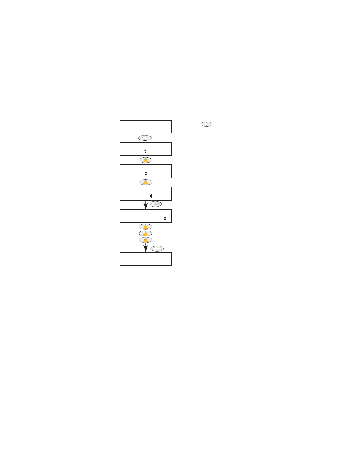
EPOWER CONTROLLER USER GUIDE
Operate ‘Return’ [rtn key] repeatedly until no further changes occur,
then hold continuously operated until the access page appears.
Use up arrow key twice to select Config
Once selected, wait a few seconds or operate
‘Enter’ key for Pass code page.
Hold 4 to 5 secs
Wait or
Code =1
Code =2
Code =3
Use up arrow key to enter the Config Pass
code
Default code = 3, but this may be edited as
described in section 6.3.2
Wait or
Any Menu
Access Goto
Operator
Access Goto
Engineer
Access Pass code
Access Goto
Config
Top le vel
Config menu
6.1.2 Configuration level menu
The Configuration level menu is entered as follows (figure 6.1.2):
1. Operate the return key repeatedly, until no further changes occur, then hold the Return key
continuously operated until the ‘Access’ ‘Goto’ display appears.
2. Use the up or down arrow key until ‘Configuration’ appears.
3. Either wait for a few seconds or operate the Enter key.
4. Use the up or down arrow key to change the code to the Engineer level code (factory default = 3, but
reconfigurable in the CONFIG level Access menu)
5. Either wait for a few seconds or operate the Enter key to display the first page of the top level
Configuration menu.
0
Figure 6.1.2 Access to the Configuration level menu
Page 56 Issue 11 Dec 15
HA179769
Page 59
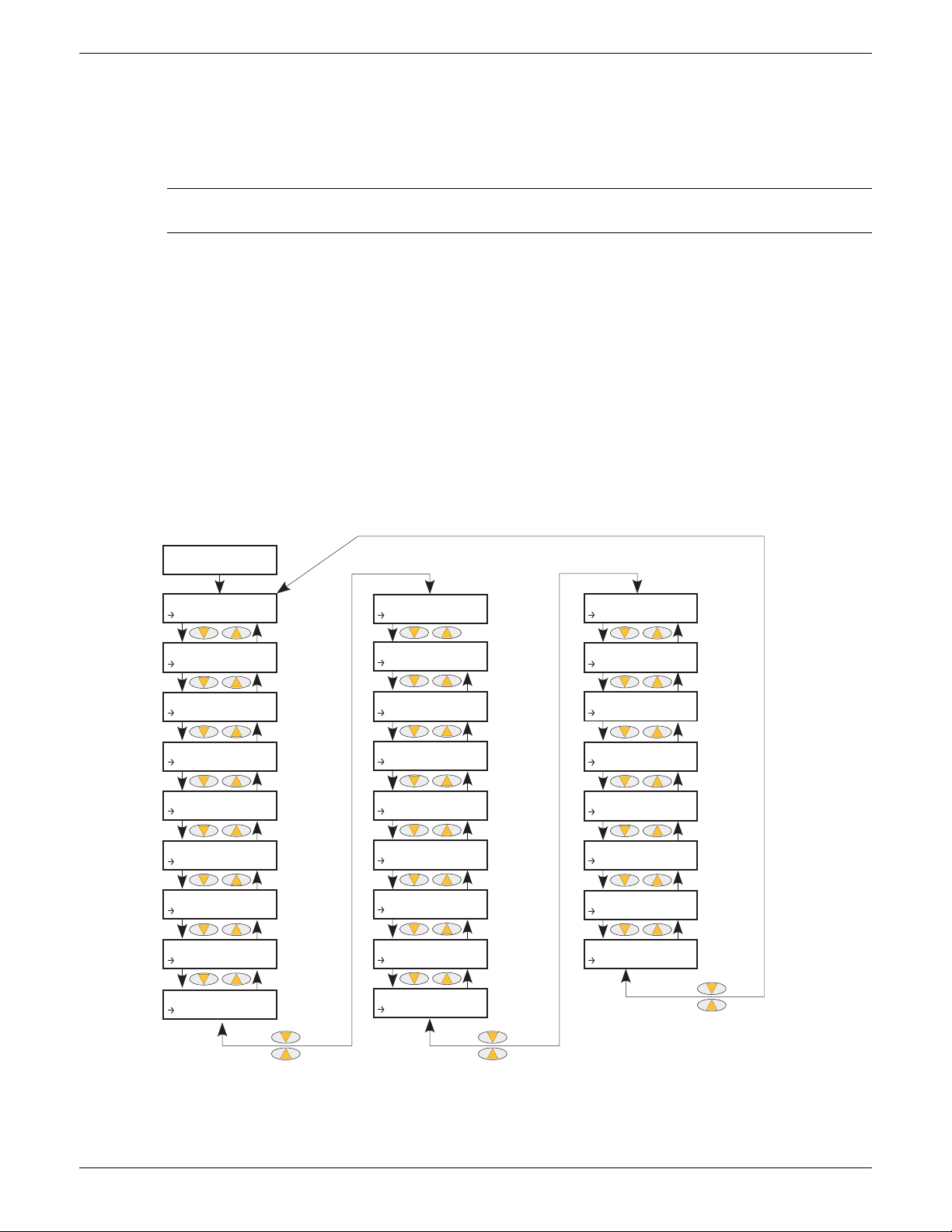
EPOWER CONTROLLER USER GUIDE
Use the up/down arrows to select the required
configuration area, then use the enter key to access
Section 6.3
Section 6.4
Section 6.5
Section 6.6
Section 6.7
Section 6.8
Section 6.9
Section 6.10
Section 6.11
Section 6.12
Section 6.13
Section 6.14
Section 6.15
Section 6.16
Section 6.17
Section 6.18
Section 6.19
Section 6.20
Section 6.21
Section 6.22
Section 6.23
Section 6.24
Section 6.25
Section 6.26
Section 6.27
Section 6.28
Pass code = 3
CONF
Access
CONF
AnalogIP
CONF
AnalogOP
CONF
Comms
CONF
Control
CONF
Count
CONF
Digital
CONF
Energy
CONF
EventLog
CONF
Faultdet
CONF
FiringOP
CONF
Instr
CONF
IPMon
CONF
Lgc2
CONF
Lgc8
CONF
Math2
CONF
Modultr
CONF
Network
CONF
PLM
CONF
PLMChan
CONF
PLMChan
CONF
Relay
CONF
SetProv
CONF
Timer
CONF
To ta l is er
CONF
UsrVal
6.2 TOP LEVEL MENU
Figure 6.2 shows the top level menu for Configuration level. Engineer top level menu similar (Default code
= 2).
Submenus are discussed in the following sections:
Note: Section 6 contains descriptions of all the menus which can appear. If an option or a feature is
not fitted and/or enabled, then it does not appear in the top level menu.
Access . . . . . . . . . . . . . . . . . . . Section 6.3
Analogue I/P . . . . . . . . . . . . . . Section 6.4
Analogue O/P . . . . . . . . . . . . . Section 6.5
Comms . . . . . . . . . . . . . . . . . . . Section 6.6
Control . . . . . . . . . . . . . . . . . . . Section 6.7
Counter. . . . . . . . . . . . . . . . . . . Section 6.8
Digital I/O. . . . . . . . . . . . . . . . . Section 6.9
Energy. . . . . . . . . . . . . . . . . . . . Section 6.10
Event Log . . . . . . . . . . . . . . . . . Section 6.11
Fault Detection . . . . . . . . . . . . Section 6.12
Firing O/P. . . . . . . . . . . . . . . . . Section 6.13
Instrument . . . . . . . . . . . . . . . . Section 6.14
IP Monitor. . . . . . . . . . . . . . . . . Section 6.15
Lgc2 logic operator. . . . . . . . Section 6.16
Lgc8 logic operator. . . . . . . . Section 6.17
Math2. . . . . . . . . . . . . . . . . . . . Section 6.18
Modulator . . . . . . . . . . . . . . . . Section 6.19
Network. . . . . . . . . . . . . . . . . . Section 6.20
Predictive Load Management Section 6.21
PLM Channels. . . . . . . . . . . . . Section 6.22
Load tap changer. . . . . . . . . . Section 6.23
Relay . . . . . . . . . . . . . . . . . . . . Section 6.24
Setpoint provider. . . . . . . . . . Section 6.25
Timer . . . . . . . . . . . . . . . . . . . . Section 6.26
Totaliser . . . . . . . . . . . . . . . . . . Section 6.27
User value . . . . . . . . . . . . . . . . Section 6.28
Figure 6.2 Top level menu
HA179769
Issue 11 Dec 15 Page 57
Page 60
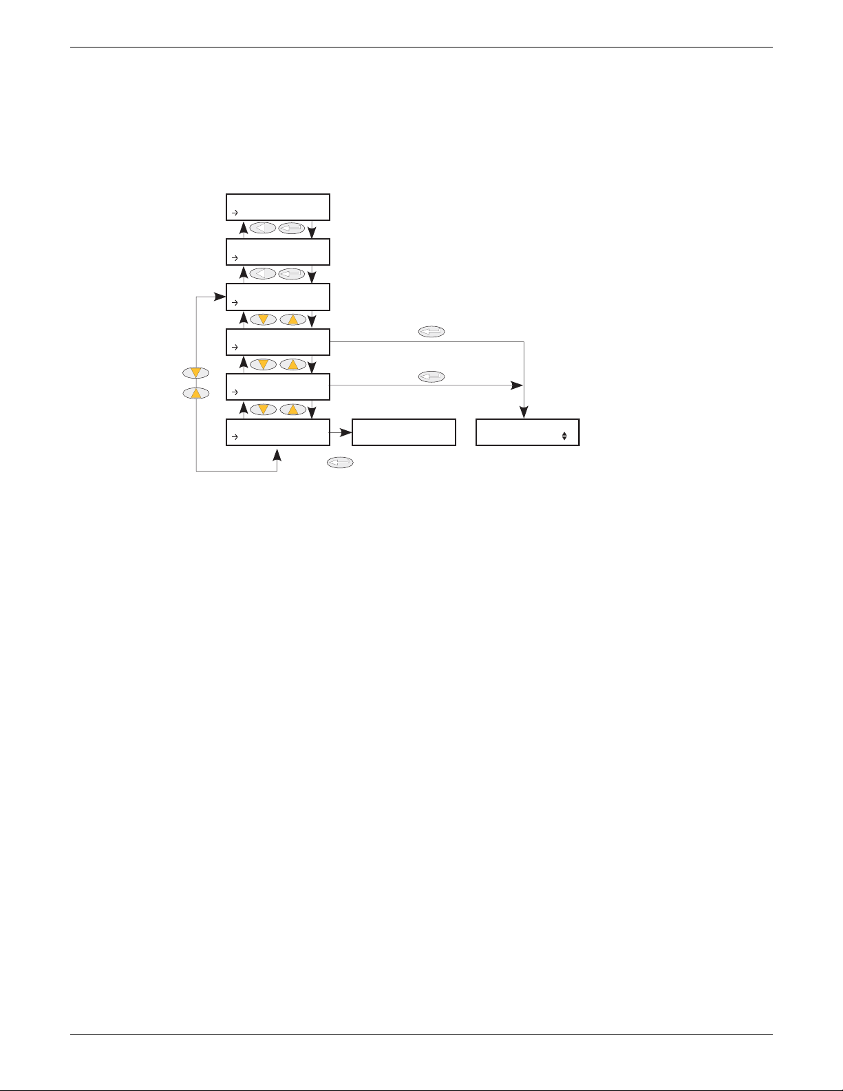
EPOWER CONTROLLER USER GUIDE
Use up/down arrows to enter
code for required level, then
wait or use ‘Enter’ key
Wait or
Wait or
Wait or
Default codes
Config = 3 Quick = 4
Operator Menu
ENG
Access
Access
Goto
Access Goto
Engineer
Access Goto
Config
Access Goto
Quick
Access Goto
Operator
Access Pass Code
6.3 ACCESS MENU
6.3.1 Engineer level menu
Entered from the Engineer top level menu, this allows the user to go to any other menu for which the access
code is known. The default access codes are Operator = 1; Engineer = 2, Config = 3, Quickstart = 4.
Figure 6.3.1 below, shows details.
0
Figure 6.3.1 Engineer level Access menu
Page 58 Issue 11 Dec 15
HA179769
Page 61
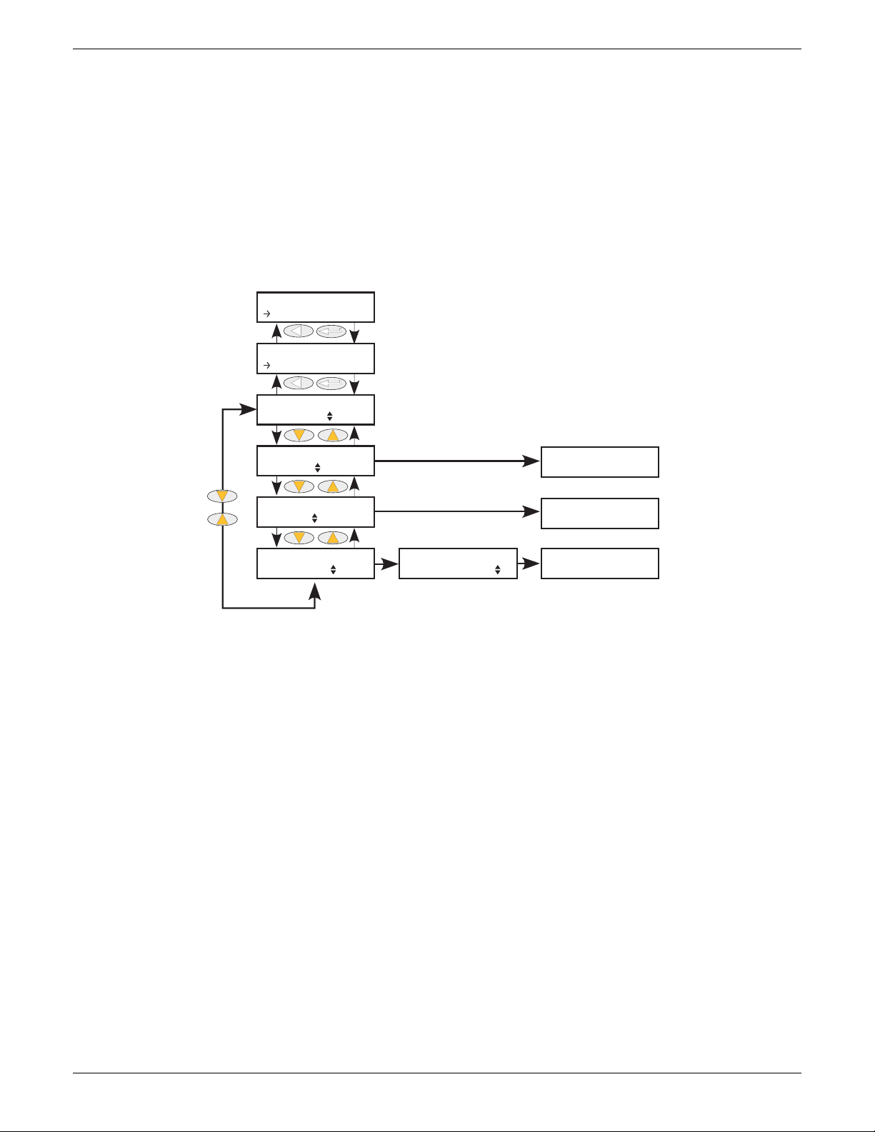
EPOWER CONTROLLER USER GUIDE
See figure 6.3.2b for other
Access menu items
Use up/down arrows to select required
level, then wait or use ‘Enter’ key
Use up/down arrows to select pass code
(default = 4) then wait or use ‘Enter’ key
Operator Menu
ENG
Access
Access
Goto
Access Goto
Config
Access Goto
Quick
Access Goto
Operator
Access Pass Code
Quick Start Menu
Engineer Menu
Access Goto
Engineer
6.3.2 Configuration level access menu
This menu allows:
1. The user to quit the Configuration level menu and ‘Goto’ a different access level. Operator and
Engineer level menus require no Pass code as they are considered to be at a lower security level than
Configuration. (Figure 6.3.2a shows the menu layout.)
2. The user to edit the current Pass codes for Engineer, Configuration and Quickstart menus (figure
6.3.2b),
3. Access to the Operator Interface push-buttons to be restricted in Operator and Engineer Level menus
(figure 6.3.2b).
GOTO MENU
4
Figure 6.3.2a GoTo menu
To change access level, the ‘Enter’ key is operated once to select ‘Goto’, then for a second time to enter the
Goto selection page.
The up/down keys are used to select the required access level. After a few seconds, or after a further entry
of the ‘Enter’ key, the unit restarts in the selected level (except for ‘Quick Start’ which requires the relevant
Pass Code (default = 4) to be entered).
HA179769
Issue 11 Dec 15 Page 59
Page 62
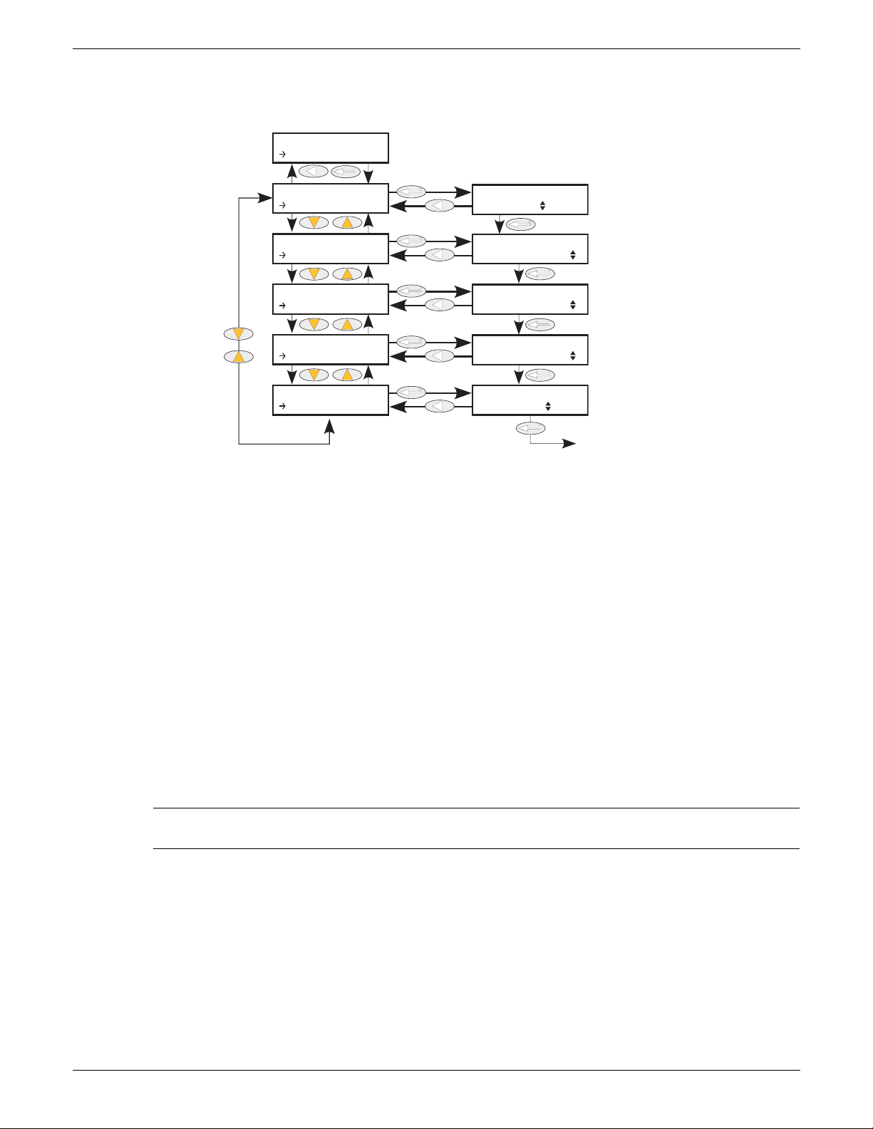
EPOWER CONTROLLER USER GUIDE
2
3
4
See figure 6.3.2a for
GoTo menu items
Use up/down arrows to set
new pass code (default = 2)
Use up/down arrows to set
new pass code (default = 3)
Use up/down arrows to set
new pass code (default = 4)
Use up/down arrows to set
user interface access for
Operator/Engineer levels
Back to ‘Goto’
(If access level left unchanged)
CONF
Access
Access
Goto
Access
Config C...
Access
Quick Co...
Access
Engineer...
Access
Keylock
Access
Goto Config
Access Engineer
Code
Access Config
Code
Access Quick
Code
Access Keylock
None
6.3.3 CONFIGURATION LEVEL ACCESS MENU (Cont.)
PASS CODE EDITING
Figure 6.3.2b Access configuration
Code As depicted above, the ‘Enter’ key is used to select ‘GoTo’, then the up/down keys are
used to select the required access level’s Pass code for editing. Once the required level
is selected (e.g. Engineer), the ‘Enter’ key is used once more, to enter the edit page,
where the current Pass Code is displayed (e.g. 2). The up/down keys can now be used
to enter a new value of between 0 and 9999. If 0 is selected, then the relevant menu
will no longer be pass code protected.
After a few seconds, the new value blinks once to confirm that it has been written into
the configuration.
KeyLock None: No restriction. All parameters at the current access level may be viewed and
edited.
All: All editing and navigation is prevented. All keys are locked so it is not
possible to ‘undo’ this action from the Operator interface. Once ‘All’ is
selected, the keyboard can be released only via iTools.
Edit: Parameter editing is possible only in Configuration level; parameters are
Read Only in other levels. In the Operator or Engineer level menus, the ‘Back’
key is still active allowing access to the ‘Goto’ menu so that the access level
may be changed if the relevant Pass code is known.
Note: Keylock is available only from the user interface (i.e. it cannot be accessed from iTools or over
a communications link.)
HA179769
Page 60 Issue 11 Dec 15
Page 63
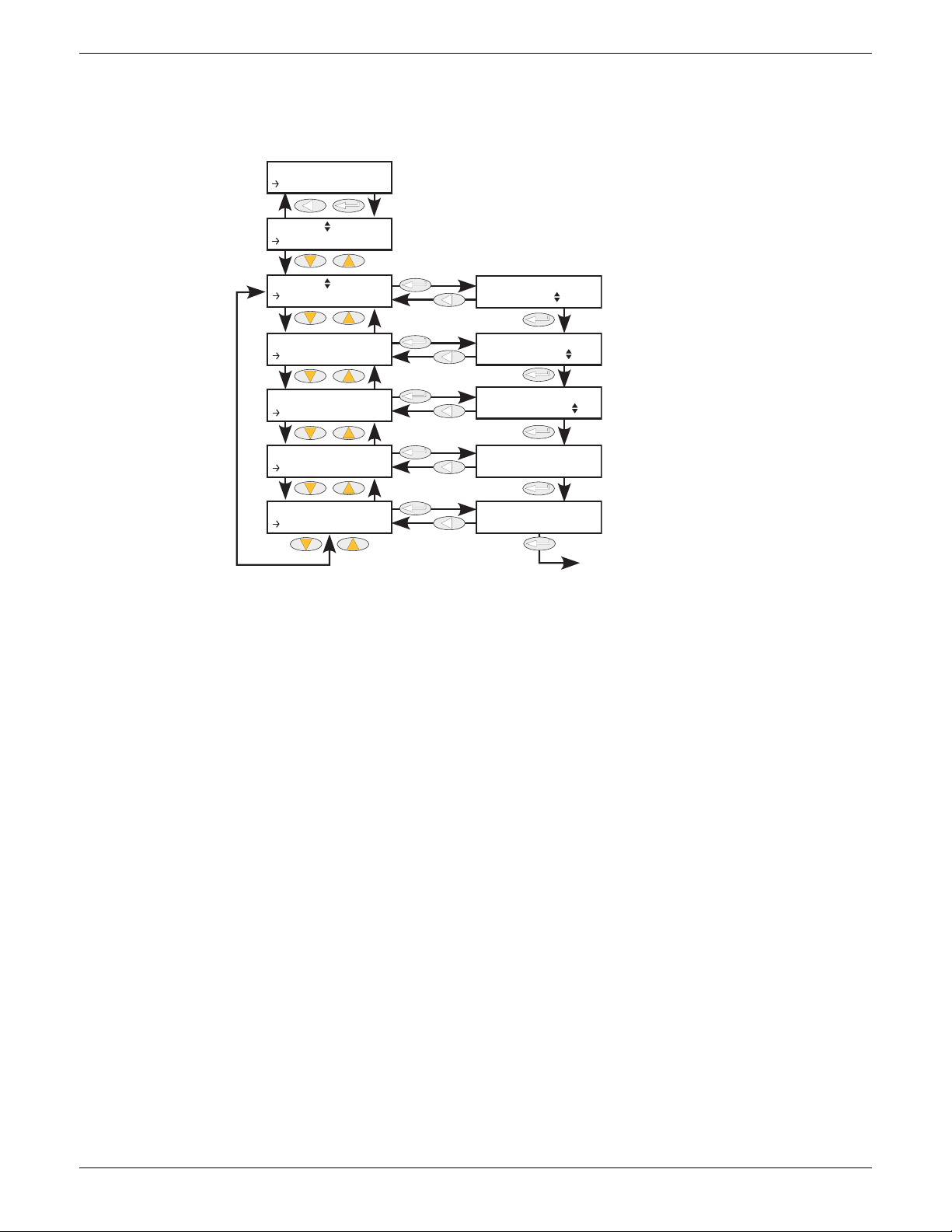
EPOWER CONTROLLER USER GUIDE
0.0
1.0
0.0
0-10V
10.0
Use up/down arrows to select AnalogIP, then ‘Enter’
Use up/down arrows to select the required Analogue input (2 in this example), then ‘Enter’
Use the up/down arrows to select the parameter to be edited
Use the up/down arrows to
select: 0 to 10V, 1 to 5V, 2 to 10V,
0 to 5V, 0 to 20mA or 4 to 20mA
Use the up/down arrows to set
Range High
Use the up/down arrows to set
Range Low
The input in process units, clipped by Range
High/Low if input is over/under range.
The input value in electrical units.
Back to’ Type’.
CONF
AnalogIP
AnalogIP 1
Ty pe
AnalogIP 2
Ty pe
AnalogIP 2
RangeHigh
AnalogIP 2
RangeLow
AnalogIP 2
PV
AnalogIP 2
MaesVal
MaesVal
PV
RangeLow
RangeHigh
Ty pe
6.4 ANALOGIP MENU
This menu item appears only if one or more analogue inputs have been configured as anything but ‘Off’ in
Quickstart, or if one or more analogue inputs has been enabled using iTools.
Figure 6.4 Analogue input menu
6.4.1 Analogue input parameters
Type Allows the type of input to be set as one of: 0 to 10V, 1 to 5V, 2 to 10V, 0 to 5V, 0 to
20mA, 4 to 20mA.
RangeHigh High range of input for scaling from measurement units to process units. PV is
clipped to range high if input goes over range.
RangeLow Low range of input for scaling from measurement units to process units. PV is
clipped to range low if input goes under range.
PV The scaled value in process units. Clipped to the Range High or Range Low value if
MeasVal The value at the instrument terminals in electrical units.
HA179769
Issue 11 Dec 15 Page 61
the signal goes over range or under range respectively.
Page 64
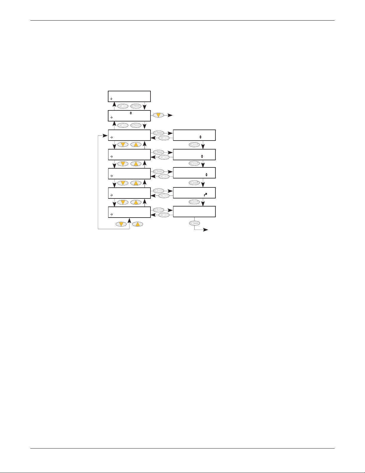
EPOWER CONTROLLER USER GUIDE
0.0
0.0
0.0
0-10V
100.0
Use up/down arrows to select AnalogOP, then ‘Enter’
Use up/down arrows to select the required Analogue output, then ‘Enter’
Use up/down arrows to select parameter to edit
See figure 6.5.2 for Alarm parameters
Use the up/down arrows to select:
0 to 10V, 1 to 5V, 2 to 10V, 0 to 5V,
0 to 20mA or 4 to 20mA.
Use the up/down arrows to set
Range High
Use the up/down arrows to set
Range Low
Input value for retransmission
Output value (PV scaled to Range low and Range
high values)
Back to’ Type’.
CONF
AnalogOP
AnalogOP 1
Ty pe
Main
Ty pe
Main
RangeHigh
Main
RangeLow
Main
PV
Main
MeasVal
MeasVal
PV
RangeLow
RangeHigh
Ty pe
6.5 ANALOGOP MENU
This menu item appears only if one or more analogue outputs have been configured as anything but ‘Off’ in
Quickstart, or if one or more analogue outputs has been enabled using iTools.
This provides a current or voltage output scaled from a Process Variable (PV) using Range High and Range
Low. Figure 6.5.1 shows the ‘Main’ configuration submenu; figure 6.5.2 shows the alarm parameters.
6.5.1 Analogue output ‘Main’ submenu parameters
Figure 6.5.1 Analogue output ‘Main’ menu
Type Allows the output type to be set as one of: 0 to 10V, 1 to 5 V, 2 to 10V, 0 to 5V, 0 to
20mA, 4 to 20mA.
RangeHigh Used to scale the Process Variable (PV) from Process units to electrical units.
RangeLow Used to scale the PV from Process units to electrical units.
PV The value to be output by the analogue output.
MeasVal The electrical output value derived by mapping the input PV via input range to
output range.
Page 62 Issue 11 Dec 15
HA179769
Page 65
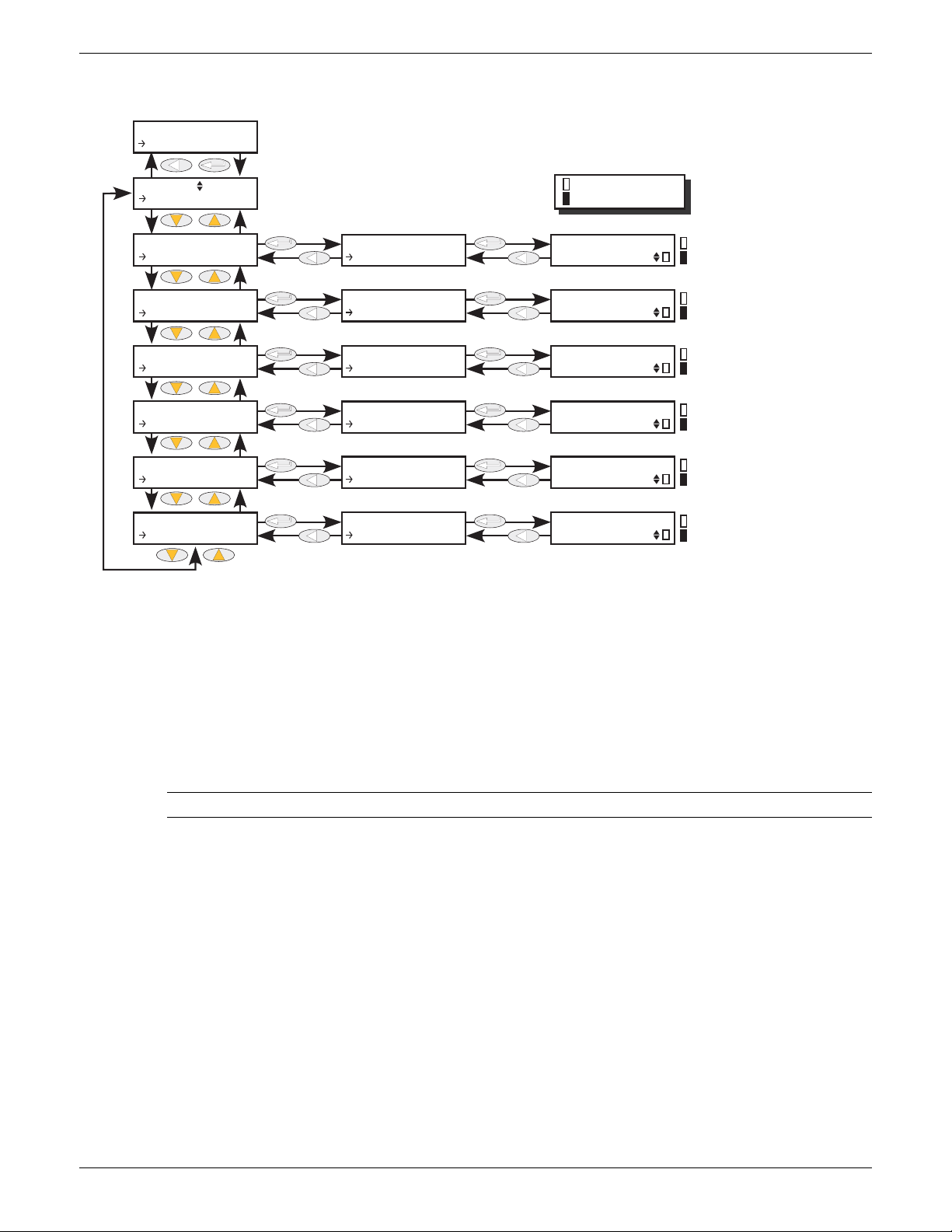
EPOWER CONTROLLER USER GUIDE
Use up/down arrows to select AnalogOP, then ‘Enter’
Use up/down arrows to select the required Analogue output, then ‘Enter’
Use up/down arrows to select parameter to edit
See figure 6.5.1 for ‘Main’ menu
Key is yellow outline
Key is solid yellow
= Alarm enabled;
= Alarm disabled
= Alarm not detected;
= Alarm detected
= Alarm not detected;
= Alarm detected
= Alarm not latched;
= Alarm latched
= Alarm not acknowledged;
= Alarm acknowledged
= output enabled;
= output stopped on alarm
CONF
AnalogOP
AnalogOP 1
Main
AnalogOP 1
AlmDis
AnalogOP 1
AlmDet
AnalogOP 1
AlmSig
AnalogOP 1
AlmLat
AnalogOP 1
AlmAck
AnalogOP 1
AlmStop
AlmDis
Output F...
AlmDet
Output F...
AlmSig
Output F...
AlmLat
Output F...
AlmAck
Output F...
AlmStop
Output F...
Output Fault
Output Fault
Output Fault
Output Fault
Output Fault
Output Fault
6.5.2 Analogue output ‘Alm’ parameters
AlmDis Allows the user to view the current disable status of the output Fault alarm.
AlmDet Indicates whether the alarm has been detected and is active.
AlmSig Signals that the alarm has occurred and whether it is latched. To assign the alarm to a
AlmLat Allows the user to set the alarm as latching or non-latching.
AlmAck Allows the user to view the current acknowledgement status of the output Fault
AlmStop Allows the user to set up the alarm to disable Power Module firing whilst active.
Figure 6.5.2 Analogue output alarm parameter access
relay (for example), it is the AlmSig parameter that should be wired.
alarm.
Note: Output fault may be triggered by either short circuit or open circuit.
HA179769
Issue 11 Dec 15 Page 63
Page 66
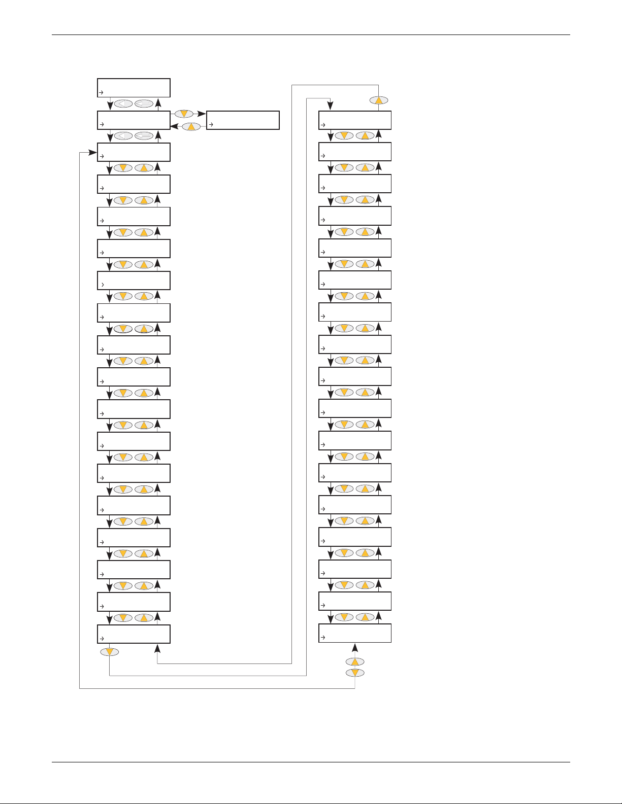
6.6 COMMS MENU
Displays type of communications fitted
See fig 6.6.2
Displays the protocol for the type of
communications fitted
Allows Baud Rate to be selected for
relevant protocols. Selectable values
depend on communications type
Allows the unit address to be set. Each
instrument on the link must have a
unique address.
Displays the number of addresses
occupied by this EPower unit (See text
for details).
Allows ‘Odd’, ‘Even’ or ‘None’ to be
selected for relevant protocols.
Select Comms delay on or off for relevant protocols.
Allows Unit ID checking ensble to
be set up.
Choose ‘Fixed’ or ‘Dynamic’.
Enter first Byte of IP address.
E.G. 111.222.333.444
Enter second Byte of IP address.
E.G. 111.222.333.444
Enter third Byte of IP address.
E.G. 111.222.
333.444
Enter fourth Byte of IP address.
E.G. 111.222.333.444
Enter first Byte of Subnet Mask address.
E.G. 111.222.333.444
Enter second Byte of Subnet Mask
address. E.G. 111.222.333.444
Enter third Byte of Subnet Mask address.
E.G. 111.222.333.444
Enter fourth Byte of Subnet Mask
address.
Enter first Byte of Gateway address.
E.G.
111.222.333.444
Enter second Byte of Gateway address.
E.G. 111.222.333.444
Enter third Byte of Gateway address.
E.G. 111.222.333.444
Enter fourth Byte of Gateway address.
E.G. 111.222.333.
444
Enter first Byte of Preferred Master address.
E.G.
111.222.333.444
Enter second Byte of Preferred Master
address.
Enter third Byte of Preferred Master address.
E.G. 111.222.333.444
Enter fourth Byte of Preferred Master
address.
Select ‘Yes’ to view MAC
address or ‘No’ to hide MAC
First Byte of MAC address
E.G. 11.22.33.44.55.66
(Appears only if ‘Show MAC’ = ‘Yes’.
Second Byte of MAC address
E.G. 11.22.33.44.55.66
(Appears only if ‘Show MAC’ = ‘Yes’.
Third Byte of MAC address
E.G. 11.22.
33.44.55.66
(Appears only if ‘Show MAC’ = ‘Yes’.
Fourth Byte of MAC address
E.G. 11.22.33.
44.55.66
(Appears only if ‘Show MAC’ = ‘Yes’.
Fifth Byte of MAC address
E.G. 11.22.33.44.
55.66
(Appears only if ‘Show MAC’ = ‘Yes’.
Sixth Byte of MAC address
E.G. 11.22.33.44.55.66
(Appears only if ‘Show MAC’ = ‘Yes’.
Shows status of Ethernet network
CONF
Comms
Comms
User
User
Ident
User
Protocol
User
Baud Rate
User
Address
User
Occupied...
User
Parity
User
Comms De...
User
Unit IDe...
User
DHCP ena...
User
IP1 Addr...
User
IP2 Addr
User
IP3 Addr
User
IP4 Addr
User
Subnet1...
User
Subnet2...
User
Subnet3...
User
Subnet4...
User
Gateway1
User
Gateway2
User
DefGate3
User
DefGate4
User
IP1 Pref...
User
IP2 Pref...
User
IP3 Pref...
User
IP4 Pref...
User
Show MAC
User
MAC1
User
MAC2
User
MAC3
User
MAC4
User
MAC5
User
MAC6
User
Network
Comms
RmtPanel
EPOWER CONTROLLER USER GUIDE
Figure 6.6 Communications User menu
HA179769
Page 64 Issue 11 Dec 15
Page 67
EPOWER CONTROLLER USER GUIDE
Number of
occupied stations
Maximum No. of
input definitions
Maximum No. of
output definitions
1 3 4
278
3 11 12
41516
Input definition:
2-byte word parameter to be read by the master.
Output definition:
2-byte word parameter to be written by master.
Local network information
(IP address, subnet mask
address etc.) is normally supplied by the user’s IT department.
6.6 COMMS MENU (Cont.)
This menu allows the user to view, and in some cases, to edit communications parameters associated with
the communications option. The user may also view the Address and Baud Rate parameters associated with
the Remote Panel option.
6.6.1 Communications User menu parameters
The following parameter list includes all parameters which can appear. Only those parameters which are
relevant to the fitted communications option appear in the menu list.
ID Displays the type of communications board fitted: RS-485 (EIA 485), Ethernet, or a
Network comms board such as Profibus or DeviceNet. (These options are fully
discussed in the Communications manual, HA179770.) ID is not user editable.
Protocol Read only. Displays the current transmission protocol: Modbus, Modbus TCP,
Network, Profibus, DeviceNet, CANopen, CC-Link, EtherNet/IP.
Baud Allows the Baud rate setting for the unit to be set. Available values vary according to
the type of communications board fitted.
Address Allows the instrument address to be set up. Each instrument in a communications
link must have a unique address allocated to it. The available address ranges vary
according to link protocol.
Occupied Stations Appearing for CC-Link protocol only, this read-only value shows the number of
addresses occupied by the unit, according to the number of input and output
definitions are set up (in iTools Fieldbus I/O Gateway) , and as shown in the table
below. For example, if the address of this unit is 4, and the number of occupied
stations is 3, then the next available address is 7.
Parity Allows the parity setting to be selected as None, odd or Even. None is often used
Delay Selects Transmission Delay ‘On’ or ‘Off’. ‘On’ inserts a guaranteed 10 millisecond
Unit ident Enables/disables the checking of the Modbus TCP Unit Identity field.
DHCP Enable Allows the user to choose whether the IP address and subnet mask are fixed or to be
IP1 Address The first byte of the IP address. (If the IP address were to be 111.222.333.444, then
IP2 to IP4 Address As IP address 1, but for the remaining three Bytes.
Subnet1 to Subnet4 Mask
Gateway1 to 4 As IP Address 1 to 4, but for the Default Gateway.
IP1 Pref Master to IP4 Pref Master
HA179769
Issue 11 Dec 15 Page 65
because there are other corruption detection methods (e.g. CRC) in use, and
selecting ‘Odd’ or ‘Even’ increases the number of bits transmitted, thus reducing
throughput.
delay between reception and response. This is needed by some converter boxes in
order to switch driver direction.
Strict: The Modbus TCP Unit Identity Field (UIF) does not have to match the
instrument address. The instrument responds only to Hex value FF in the UIF.
Loose: The Modbus TCP Unit Identity Field (UIF) does not have to match the
instrument address. The instrument responds any value in the UIF.
Instr: The Modbus TCP Unit Identity Field (UIF) must match the instrument address
or no response will be made to messages.
A value of 0 in the UIF is treated as a ‘Broadcast Message’.
supplied by a DHCP Ethernet server.
the first byte would be 111; the second byte 222, and so on).
As IP Address 1 to 4, but for the Subnet Mask
As for IP Address 1 to 4, but for the Preferred Master.
Page 68
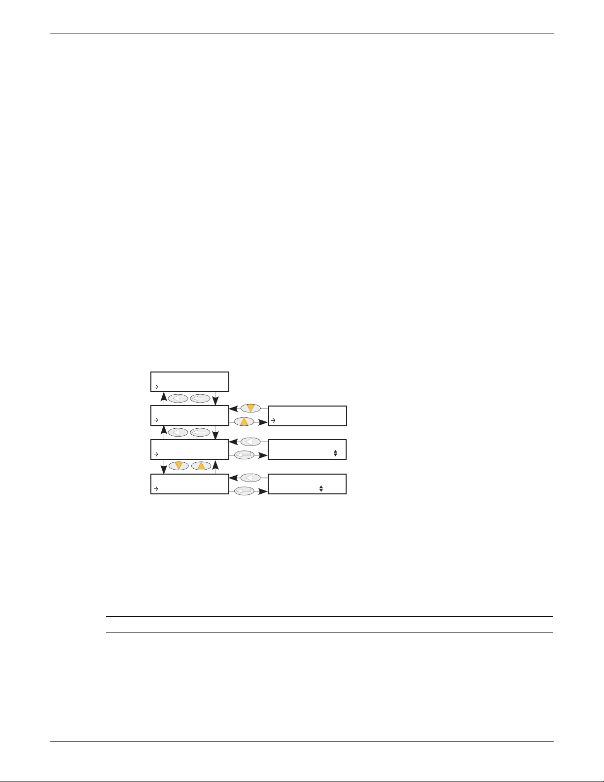
EPOWER CONTROLLER USER GUIDE
See fig 6.6
Set a unique address between 1 and 254
inclusive for each instrument
Use the up/down arrows to select
9600 or 19200 as Baud rate for the
remote panel network
CONF
Comms
Comms
RmtPanel
Rmt Panel
Address
Rmt Panel
Baud
Address
Baud
Comms
User
6.6.1 COMMUNICATIONS USER MENU PARAMETERS (Cont.)
Show MAC Allows the user to choose whether the unit’s MAC address may be shown (Yes), or
not (No).
MAC1 Appears only if Show MAC (above) is set to ‘Yes’. This is the first byte of the non-
editable MAC address. (If the MAC address were to be 11.22.33.44.55.66 then the
first byte would be 11; the second byte 22, and so on).
MAC2 to MAC6 As for MAC1, but for bytes two to six respectively
Network Read Only. Also known as ‘Ethernet Status’. Shows the status of the communictions
link, as follows:
Running:
Init:
Ready:
Offline:
Bad:
NetStatus Read Only. Appears to ‘Fieldbus’ protocols only. Shows the status of the
communications network, as follows:
Setup:
Init:
Ready:
Idle:
Active:
Error:
Fault:
Link connected and running
Communications initialising
Network ready to accept connection
Network offline
Network Status Bad GSD (Profibus only)
Anybus module set-up in progress
Anybus module is initialising network-specific functionality
Process Data channel ready but inactive
Interface is inactive
Process Data channel is active and error free
One or more errors have been detected
Host fault detected.
6.6.2 COMMS REMOTE PANEL PARAMETERS
1
9600
Figure 6.6.2 Communications remote panel menu
Address Each instrument on the link must be given a unique address between 1 and 254
inclusive.
This may be the same or different from the address set in the CONF ‘User’ Menu
(section 6.6.1).
Baud Displays the Baud rate for the Remote panel communications. Either 9600 or 19200.
This may be the same or different from the Baud rate set in the CONF ‘User’ Menu
(section 6.6.1).
Note: Remote Panel parity setting should be set to ‘No parity’ or ‘None’.
Page 66 Issue 11 Dec 15
HA179769
Page 69
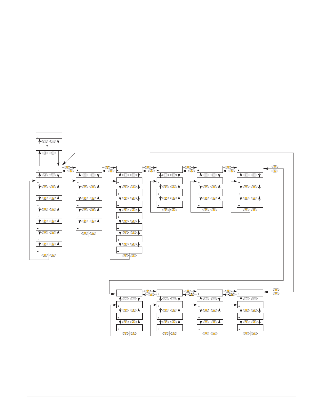
EPOWER CONTROLLER USER GUIDE
Use up/down arrows, to select the required control algorithm, then Enter. Use
return key one or more times from within menu to return to this page
Section 6.7.1
Section 6.7.2
Section 6.7.3
Section 6.7.4
Section 6.7.5
Section 6.7.6
Section 6.7.7
Section 6.7.8
Section 6.7.9
Section 6.7.10
CONF
Comms
Control N
Control
Setup
Setup
Standby
Setup
NominalPV
Setup
Limit En...
Setup
Tra ns E n.. .
Setup
FF Type
Setup
FF Gain
Setup
FF Offset
Control
Main
Control
Limit
Control
Diag
Control
AlmDis
Control
AlmDet
Main
PV
Main
SP
Main
Tra ns P V
Main
Trans SP...
Main
TI
Limit
PV1
Limit
PV2
Limit
PV3
Limit
SP1
Limit
SP2
Limit
SP3
Limit
TI
Diag
Status
Diag
Output
Diag
PA Li mit
AlmDis
ClosedLo...
AlmDis
PVTransf...
AlmDis
Limitati...
AlmDet
ClosedLo...
AlmDet
PVTransf...
AlmDet
Limitati...
Control
AlmSig
AlmSig
ClosedLo...
AlmSig
PVTransf...
AlmSig
Limitati...
Control
AlmLat
AlmLat
ClosedLo...
AlmLat
PVTransf...
AlmLat
Limitati...
Control
AlmAck
AlmAck
ClosedLo...
AlmAck
PVTransf...
AlmAck
Limitati...
Control
AlmStop
AlmStop
ClosedLo...
AlmStop
PVTransf...
AlmStop
Limitati...
6.7 CONTROL MENU
The control menu provides the control algorithm to perform power control and transfer, threshold limiting
and phase angle reduction (in the case of burst firing). Figure 6.7, below, gives an overview of the menu,
which is described in the following sections:
6.7.1
6.7.2
6.7.3
6.7.4
6.7.5
6.7.6
6.7.7
6.7.8
6.7.9
6.7.10
Setup
Main
Limit
Diag (Diagnostics)
AlmDis (Alarm disable)
AlmDet (Alarm detection)
AlmSig (Alarm signalling)
AlmLat (Alarm latch)
AlmAck (Alarm Acknowledge)
AlmStop (Stop firing on alarm)
Figure 6.7 Control menu
HA179769
Issue 11 Dec 15 Page 67
Page 70
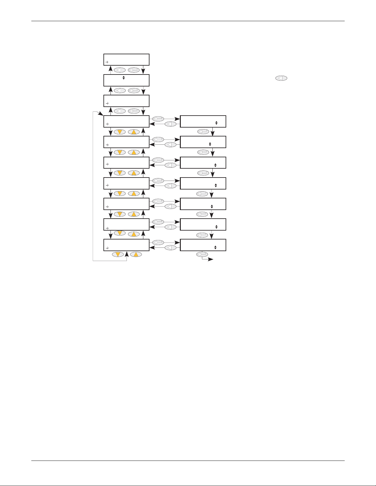
EPOWER CONTROLLER USER GUIDE
57500
Tri
0%
0.0
Use up/down arrows, to select the required control loop, then Enter. Use [rtn
return key one or more times from within menu to return to this page
Use up/down arrows to set the
unit to standby (Yes) or not (No).
Enter Nominal PV value
(see text for more details)
Enables threshold limit feature
Enable Transfer (Proportional limit)
Select the type of Feed
Forward to be used.
Enter Feed Forward gain
value to be applied.
Enter Feed Forward offset value to be applied.
Back to Standby
CONF
Control
Control N
Setup
Control
Setup
Setup
Standby
Setup
NominalPV
Setup
Limit En...
Setup
Tra n s En.. .
Setup
FF Type
Setup
FF Gain
Setup
FF Offset
Standby
Nominal PV
Limit Enable
Trans Enable
FF Type
FF Gain
FF Offset
6.7.1 Control Setup Parameters
This contains parameters for setting the type of control to be performed.
Figure 6.7.1 Control setup menu
Standby If Yes, the controller enters Standby mode and zero % power is demanded. When
removed from Standby the unit returns to operating mode in a controlled manner.
Nominal PV Normally the nominal value for each control type. For example, for feedback mode =
Limit Enable Used to enable/disable threshold limit.
2
, Vsq should be wired to the Main PV, and Nominal PV set to the nominal value
V
expected for V
2
(usually VLoadNominal2).
Trans Enable Select Transfer Enable (Proportional limit) as ‘Yes’ (enabled) or ‘No’ (not enabled).
FFType Feedforward Type.
Off: Feedforward is disabled
Trim :
FFonly:
Feedforward is for use only with the main control elements, and the limit loop will
Feedforward value is the dominant element of the output. Trimmed by
the control loop based on the Main PV and setpoint.
The feedforward value is the output from the controller. Open loop
control may be configured by this means.
override feedforward.
FFGain The entered gain value is applied to the Feedforward input.
FFOffset The entered value is applied to the Feedforward input after the Gain value has been
applied to it.
Page 68 Issue 11 Dec 15
HA179769
Page 71
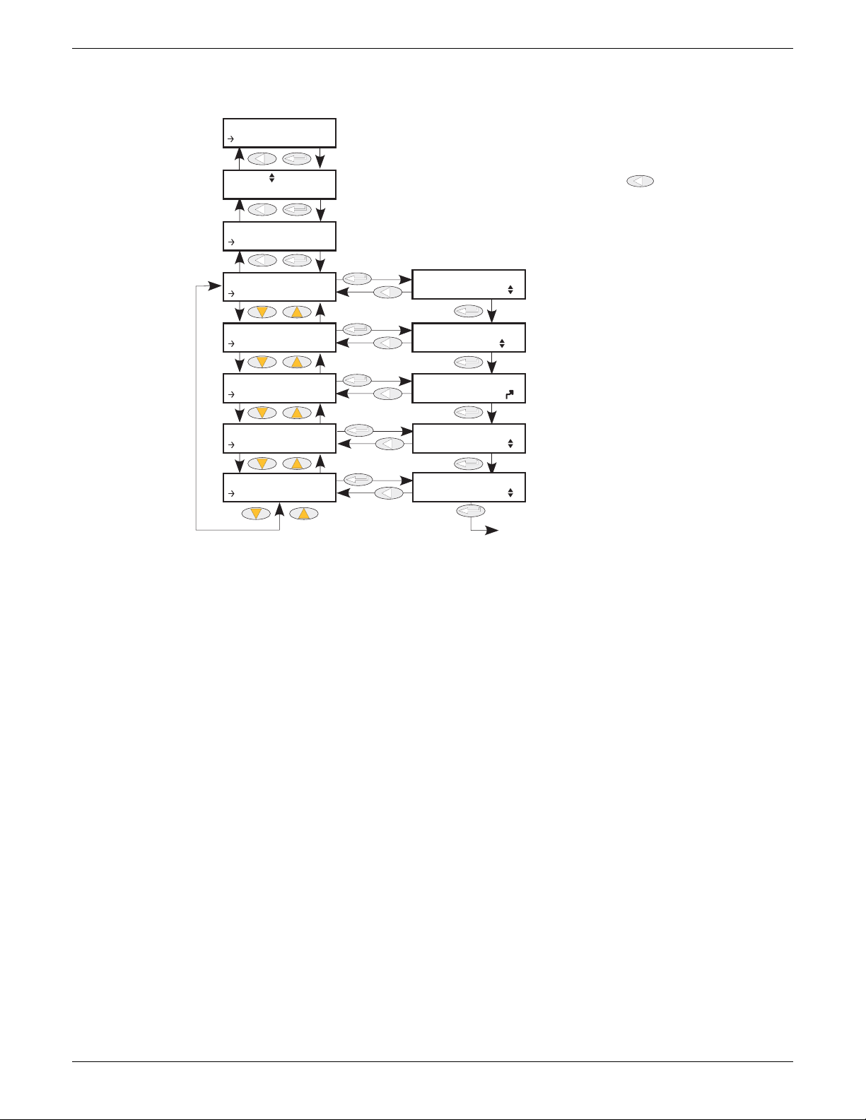
EPOWER CONTROLLER USER GUIDE
0
0.0
0
0
1
Use up/down arrows, to select the required control loop, then Enter. Use [rtn
return key one or more times from within menu to return to this page
Use up/down arrows to set the value of
the Main PV of the controller
Use the up/down arrows to set
the main Setpoint
(% of Nominal PV).
The PV measurement for transfer.
Use the up/down arrows to define the
span of operation for transfer.
Use the up/down arrows to define the
integration time of the main PI loop
Back to PV
Use up/down arrows, to select ‘Main’, then Enter.
CONF
Control
Control N
Setup
Control
Main
Main
PV
Main
SP
Main
Tra n s PV
Main
Tra n s Sp.. .
Main
TI
TI
Trans Span
Tra n s PV
SP
PV
6.7.2 Control Main Parameters
This menu contains all the parameters associated with the Main control loop.
Figure 6.7.2 Control Main parameters
PV Displays the main Controller Process Variable (PV). Wired to the measurement which
2
it is to be controlled. For example, to perform V
control. Vsq should be wired to this
(PV) parameter and Nominal PV configured appropriately (section 6.7.1).
SP The Setpoint to control at, as a percentage of Nominal PV (the upper range of the
loop in engineering units). For example, if NominalPV = 500V RMS, and SP is set to
Trans PV
20%, the controller attempts to regulate at 500 x 20/100 = 100V RMS. If Transfer or
Limit is enabled, these will override SP.
Transfer PV. This is the PV measurement for transfer. For example, if a V
is required, the Vsq should be wired to MainPV and Isq to TransferPV. Appears only if
Trans Enable (section 6.7.1) is set to ‘Yes’ (via iTools).
2
to I2 transfer
Transfer Span The span of operation for transfer. Appears only if Trans Enable (section 6.7.1) is set
TI Allows the user to define an integral time for the main PI control loop.
HA179769
Issue 11 Dec 15 Page 69
to ‘Yes’ (via iTools).
Page 72
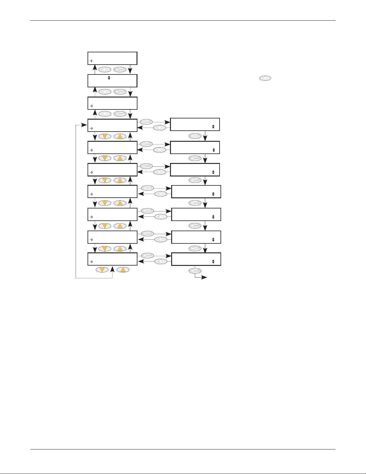
EPOWER CONTROLLER USER GUIDE
Use up/down arrows, to select the required control loop, then Enter. Use [rtn ke
return key one or more times from within menu to return to this page
The Process Variable value which
is to perform first threshold limit
control
The Process Variable value which
is to perform second threshold
limit control
The Process Variable value which
is to perform third threshold limit
control
The setpoint for PV1
The setpoint for PV3
Back to PV1
Use up/down arrows, to select ‘Limit’, then Enter.
The setpoint for PV2
Use the up/down arrows to define the integral time for the limit control loop
CONF
Control
Control N
Setup
Control
Limit
Limit
PV1
Limit
PV2
Limit
PV3
Limit
SP1
Limit
SP2
Limit
SP3
Limit
TI
PV1
PV2
PV3
SP1
SP2
SP3
TI
6.7.3 Control Limit parameters
Parameters relating to the limit control loop.
0
0
1
1
1
PV1 to PV3 Threshold value for limit loops 1 to 3 respectively. This is the value to perform
Figure 6.7.3 Control Limit menu
threshold limit control. ‘Limit Enable’ must be set to ‘Yes’ in the Setup menu (section
1
1
6.7.1).
SP1 to SP3 The setpoint for limit loops 1 to 3 respectively.
TI The integration time for the limit PI control loop.
Example:
2
If I
threshold limiting is required, Isq is wired to PV1, and the required threshold value is entered at SP1. In
phase angle configuration, the phase angle is reduced to achieve the limit setpoint; in burst firing, the unit
continues to fire in bursts, but these bursts are of phase angle in order to achieve the limit setpoint. The
modulation continues to attempt to reach the main setpoint.
Also known as phase angle reduction burst firing.
HA179769
Page 70 Issue 11 Dec 15
Page 73
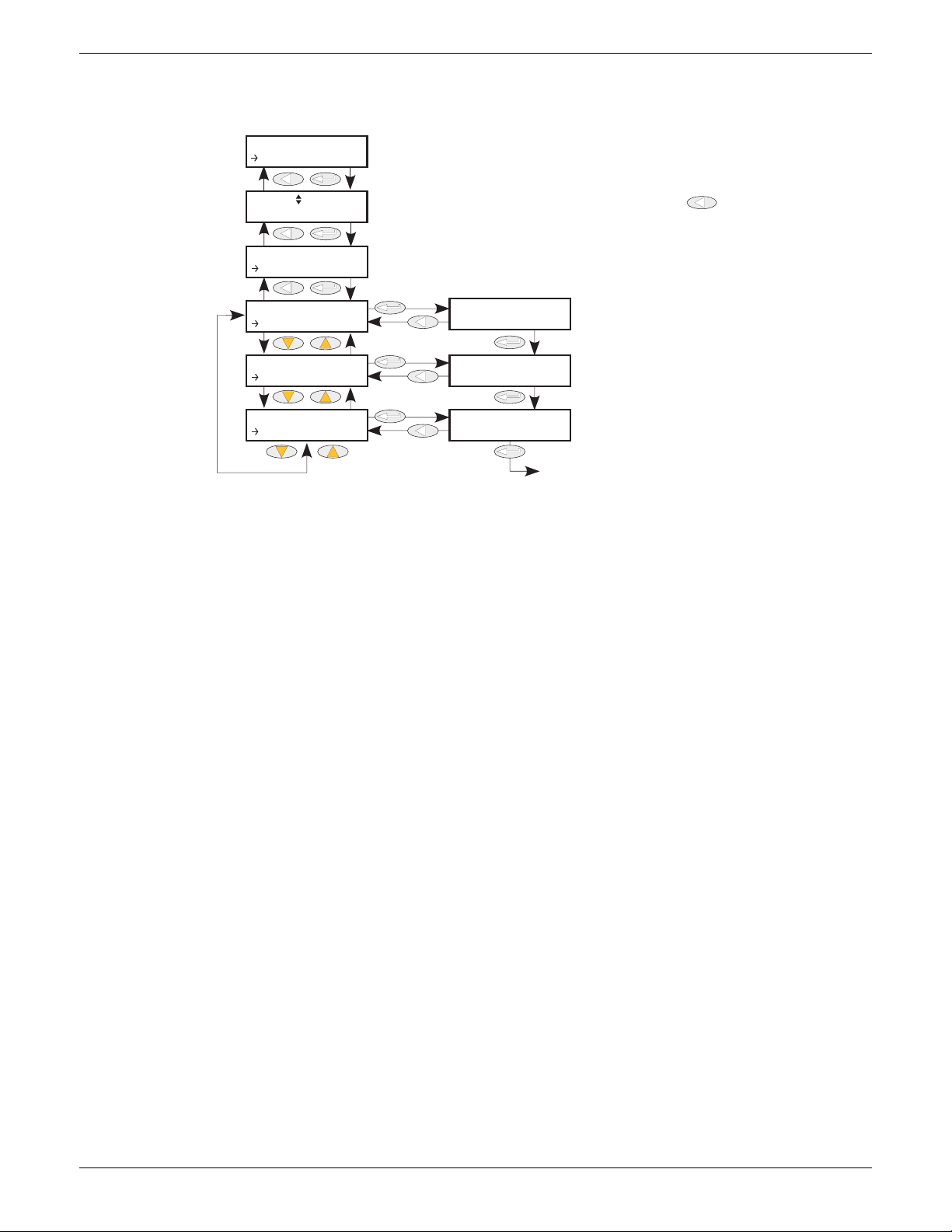
EPOWER CONTROLLER USER GUIDE
0.0
100
Use up/down arrows, to select the required control loop, then Enter. Use
return key one or more times from within menu to return to this page
Displays the current operating
state of the controller.
Displays the output demand
of the controller, in %
Phase angle output for Phase
Angle reduction in burst firing
Back to status
Use up/down arrows, to select ‘Diag’, then Enter.
CONF
Control
Control N
Setup
Control
Diag
Diag
Status
Diag
Output
Diag
PA Lim it
Status
Output
PA L im it
Main PV
6.7.4 Control Diag parameters
This menu contains diagnostic parameters related to Control.
Figure 6.7.4 Control Diag menu
Status Indicates the current operating state of the controller:
Main PV: The control strategy is using Main PV as the control input
Transfer function
active:
Limit 1(2)(3) active:
The transfer input us being used as the input to the control
strategy.
Control limiting is currently active using limit PV1(2)(3) and
limit SP 1(2)(3).
Output The current output demand in percent. Normally wired to Modulator.In or
FiringOP.In
PA Limit Applies only to Burst Firing control modes. If this parameter is wired to
FiringOP.PALimit, the power module will deliver bursts of phase angle firing
depending both on the Main Setpoint and on the Limit Setpoint.
HA179769
Issue 11 Dec 15 Page 71
Page 74
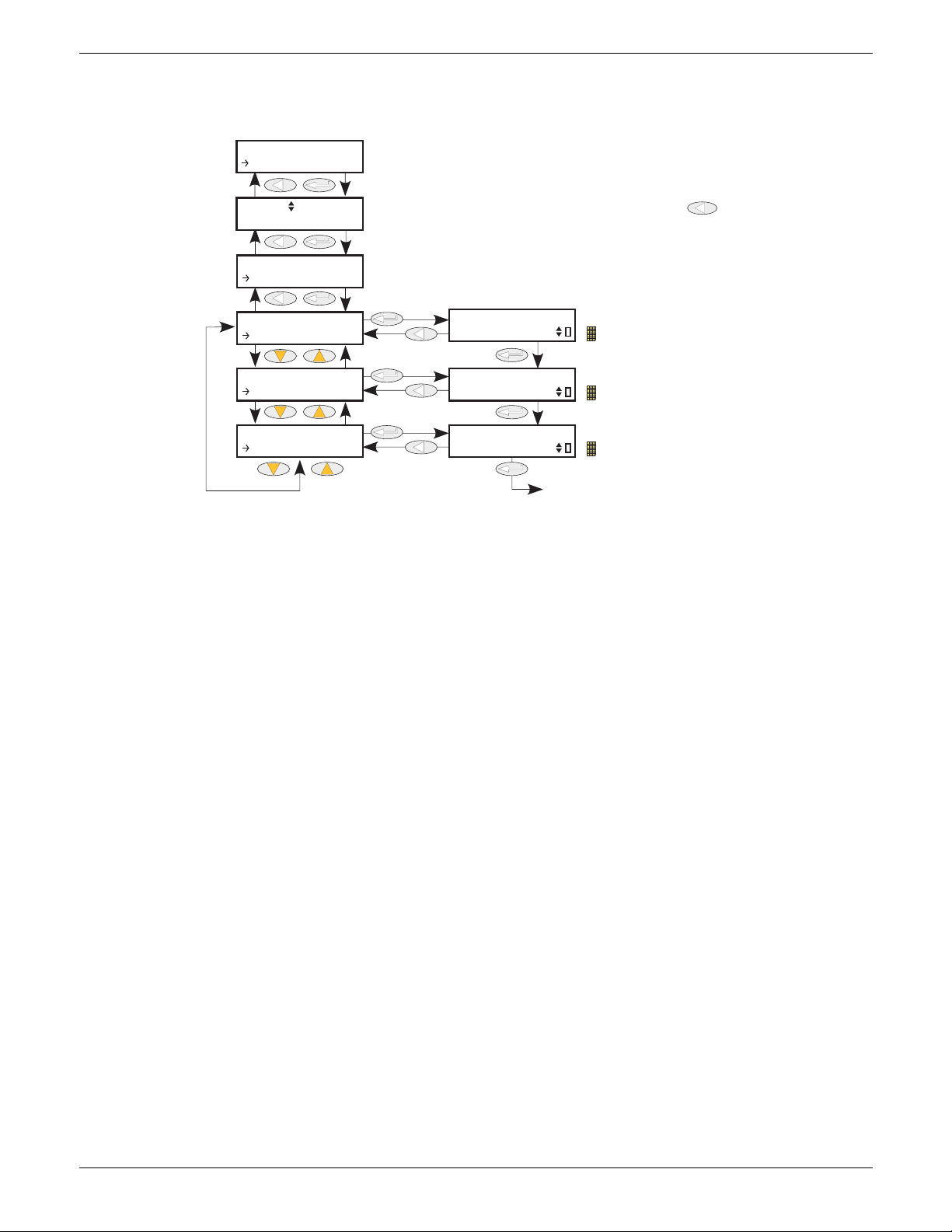
EPOWER CONTROLLER USER GUIDE
Use up/down arrows, to select the required control loop, then Enter. Use
return key one or more times from within menu to return to this page
Used to disable the ‘Loop Break’ alarm
Solid yellow = Alarm disabled
Used to disable the ‘Transfer Active’ alarm
Solid yellow = Alarm disabled
Used to disable the ‘Control Limit Active’ alarm
Solid yellow = Alarm disabled
Back to Closed Loop
Use up/down arrows, to select ‘AlmDis’, then Enter.
CONF
Control
Control N
Setup
Control
AlmDis
AlmDis
ClosedLo...
AlmDis
PVTransf...
AlmDis
Limitati...
ClosedLoop
PVTransfer
Limitation
6.7.5 Control Alarm disable parameters
Allows each alarm of the control block to be disabled, individually. May be wired.
Figure 6.7.5 Control Alarm disable menu
Closed Loop The ‘piano key’ in the bottom right corner of the display indicates the current enable
status of the closed loop alarm. The up and down arrows are used to enable/disable
the alarm. An ‘empty’ key indicates that the alarm is enabled; a solid yellow key
means that the alarm is disabled.
PV Transfer As for Closed Loop, but for the ‘Transfer Active’ alarm.
Limitation As for Closed Loop, but for the ‘Control limit active’ alarm.
Page 72 Issue 11 Dec 15
HA179769
Page 75
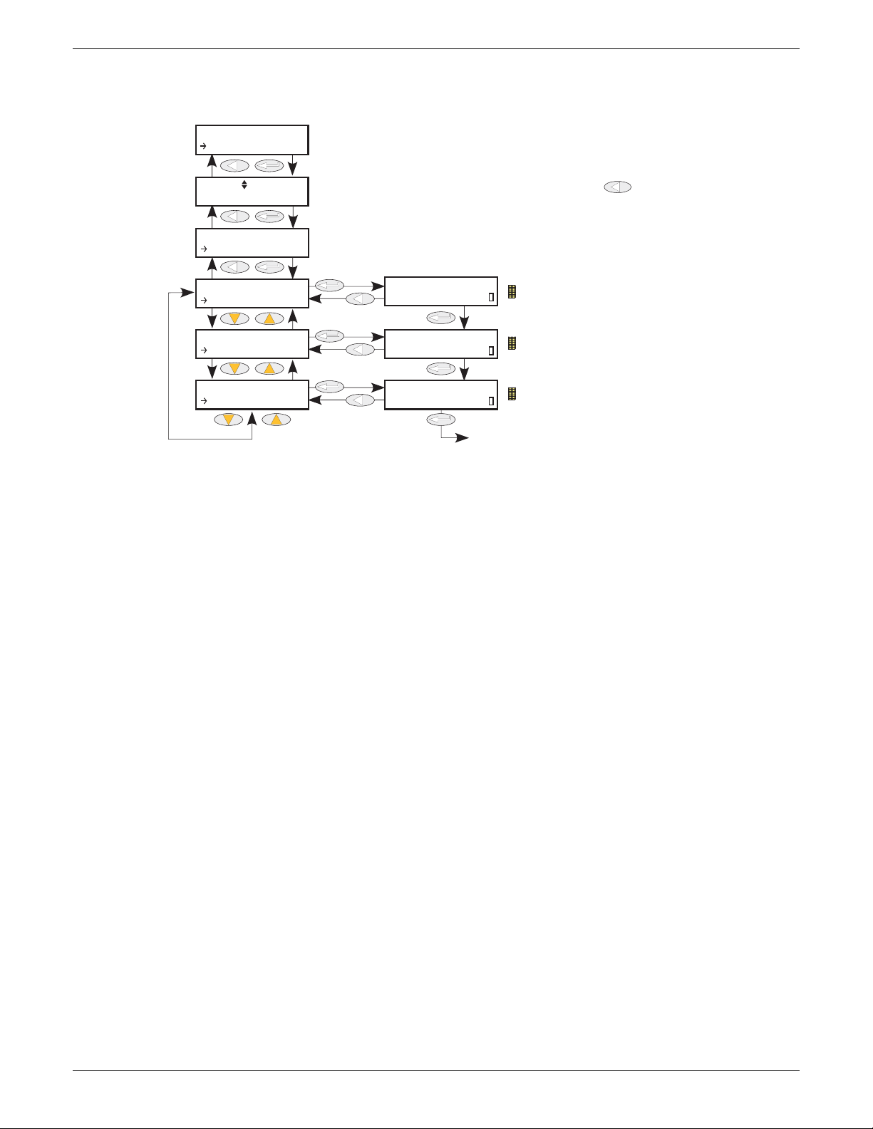
EPOWER CONTROLLER USER GUIDE
Use up/down arrows, to select the required control loop, then Enter. Use
return key one or more times from within menu to return to this page
Solid yellow = Closed loop alarm is active.
Solid yellow = Transfer is currently active
Solid yellow = Limitation control loop is active
Back to ClosedLoop
Use up/down arrows, to select AlmDet, then Enter.
CONF
Control
Control N
Standby
Control
AlmDet
AlmDet
ClosedLo...
AlmDet
PVTransf...
AlmDet
Limitati...
ClosedLoop
PVTransfer
Limitation
6.7.6 Control Alarm detection parameters
Indicates whether each alarm has been detected and whether or not it is currently active.
Figure 6.7.6 Control Alarm detection menu
Closed Loop The ‘piano key’ in the bottom right corner of the display shows whether or not the
closed loop alarm is currently active. An ‘empty’ key indicates that the alarm is
inactive; a solid yellow key means that the alarm is active.
PV Transfer As for Closed Loop, but for the ‘Transfer Active’ alarm.
Limitation As for Closed Loop, but for the ‘Control limit active’ alarm.
HA179769
Issue 11 Dec 15 Page 73
Page 76
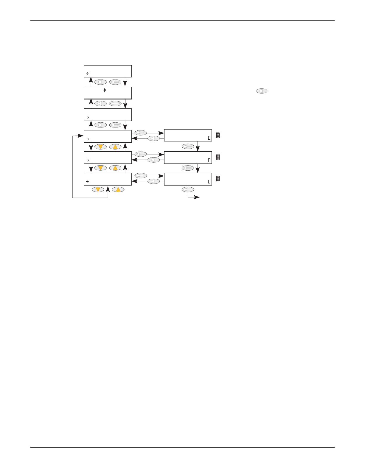
EPOWER CONTROLLER USER GUIDE
Use up/down arrows, to select the required control loop, then Enter. Use
return key one or more times from within menu to return to this page
Solid yellow = Indicates that the loop alarm has
occurred.
Solid yellow = Signals that the transfer alarm has
occurred.
Solid yellow = Signals that the transfer alarm has
occurred.
Back to ClosedLoop
Use up/down arrows, to select ‘AlmSig’, then ‘Enter’.
ClosedLoop
PVTransfer
Limitation
CONF
Control
Control N
Setup
Control
AlmSig
AlmSig
ClosedLo...
AlmSig
PVTransf...
AlmSig
Limitati...
6.7.7 Control Alarm signalling parameters
Signals that an alarm has occurred and has been latched (if so configured in ‘Alarm Latch’ (section 6.7.8)). If
it is required that an alarm is to be assigned to a relay (for example), then the appropriate alarm signalling
parameter should be used.
Figure 6.7.7 Control Alarm Signalling menu
Closed Loop The ‘piano key’ in the bottom right corner of the display indicates whether the closed
loop break alarm is currently active. An ‘empty’ key indicates that the alarm is
inactive; a solid yellow key means that the alarm is active.
PV Transfer As for Closed Loop, but for the ‘Transfer Active’ alarm.
Limitation As for Closed Loop, but for the ‘Control limit active’ alarm.
Page 74 Issue 11 Dec 15
HA179769
Page 77
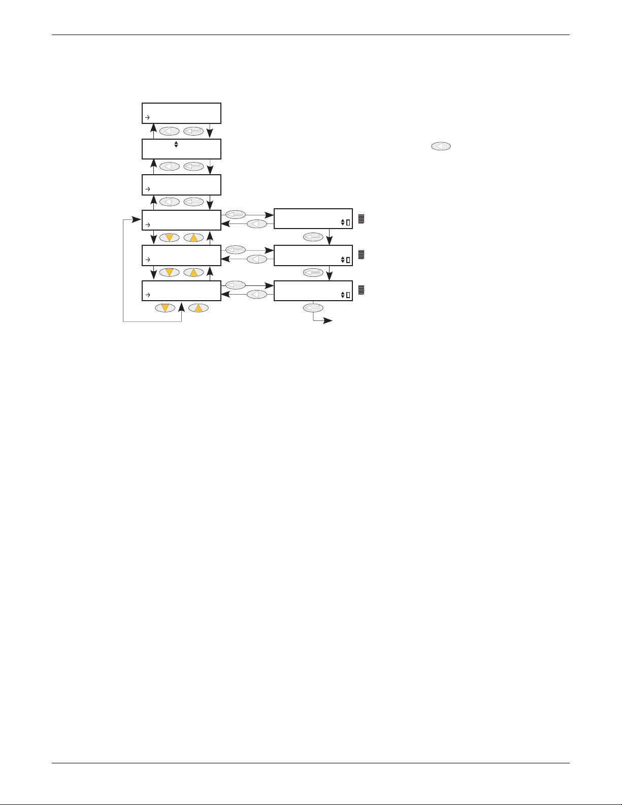
EPOWER CONTROLLER USER GUIDE
Use up/down arrows, to select the required control loop, then Enter. Use
return key one or more times from within menu to return to this page
Solid yellow = Indicates that the loop alarm is
configured as a latching alarm.
Solid yellow = Signals that the transfer alarm is
configured as a latching alarm.
Solid yellow = Signals that the limitation alarm is
configured as a latching alarm.
Back to ClosedLoop
Use up/down arrows, to select ‘AlmLat’, then Enter.
ClosedLoop
PVTransfer
Limitation
CONF
Control
Control N
Setup
Control
AlmLat
AlmLat
ClosedLo...
AlmLat
PVTransf...
AlmLat
Limitati...
6.7.8 Control Alarm Latch parameters
Allows each alarm to be configured as latching or not latching. The latched status is shown in the Network
AlmSig submenu (ref section 6.20.3).
Figure 6.7.8 Control Alarm latching menu
Closed Loop Use the up/down arrows to change the latching status of the alarm. The ‘piano key’ in
the bottom right corner of the display indicates whether the closed loop alarm is
latching (solid yellow) or non-latching (‘empty’).
PV Transfer As for Closed Loop, but for the ‘Transfer Active’ alarm.
Limitation As for Closed Loop, but for the ‘Control limit active’ alarm.
HA179769
Issue 11 Dec 15 Page 75
Page 78
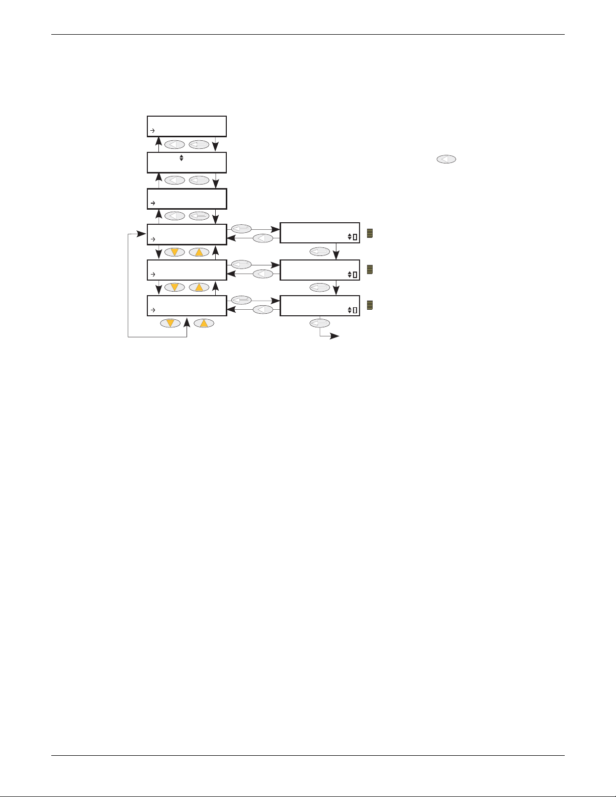
EPOWER CONTROLLER USER GUIDE
Use up/down arrows, to select the required control loop, then Enter. Use
Solid yellow = the closed loop alarm has not
been acknowledged.
Solid yellow = the transfer alarm has not been
acknowledged.
Solid yellow = the limitation alarm has not been
acknowledged.
Back to ClosedLoop
Use up/down arrows, to select ‘AlmAck’, then ‘Enter’.
ClosedLoop
PVTransfer
Limitation
CONF
Control
Control N
Control
AlmAck
AlmAck
ClosedLo...
AlmAck
PVTransf...
AlmAck
Limitati...
6.7.9 Control Alarm Acknowledgement parameters
This menu allows individual alarms to be acknowledged. On acknowledgement, the related Signalling
parameter is cleared. The Acknowledge parameters automatically clear after being written.
If the alarm is still active (as shown by the Alarm Detection display) it may not be acknowledged.
Figure 6.7.9 Control Alarm Acknowledge menu
Closed Loop The ‘piano key’ in the bottom right corner of the display shows whether the closed
loop alarm has been acknowledged or not. An ‘empty’ key indicates that the alarm is
acknowledged; a solid yellow key indicates that the alarm is unacknowledged. The
up/down arrow keys are used to acknowledge.
PV Transfer As for Closed Loop, but for the ‘Transfer Active’ alarm.
Limitation As for Closed Loop, but for the ‘Control limit active’ alarm.
Page 76 Issue 11 Dec 15
HA179769
Page 79
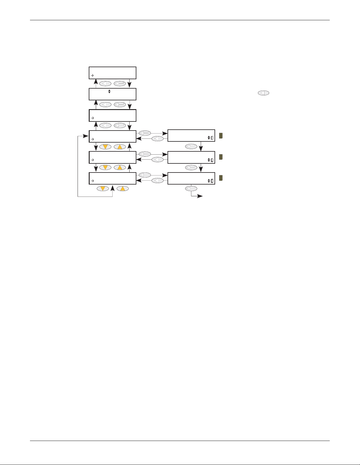
EPOWER CONTROLLER USER GUIDE
Use up/down arrows, to select the required control loop, then Enter. Use
return key one or more times from within menu to return to this page
Solid yellow = the closed loop alarm prevents firing when active.
Solid yellow = the transfer alarm prevents firing when active.
Solid yellow = the limitation alarm prevents firing when active.
Back to ClosedLoop
Use up/down arrows, to select ‘AlmStop’, then Enter.
ClosedLoop
PVTransfer
Limitation
CONF
Control
Control N
Setup
Control
AlmStop
AlmStop
ClosedLo...
AlmStop
PVTransf...
AlmStop
Limitati...
6.7.10 Control Alarm Stop parameters
Allows individual channels to be configured such that it will stop the associated power channel from firing
whilst the alarm is active. This feature is activated by the signalling parameters, so the alarm stop may be
latching.
Figure 6.7.10 Control Alarm Stop menu
Closed Loop The ‘piano key’ in the bottom right corner of the display shows whether the closed
loop alarm has been configured to disable firing or not. An ‘empty’ key indicates that
the firing is enabled; a solid yellow key indicates that the firing is disabled.
PV Transfer As for Closed Loop, but for the ‘Transfer Active’ alarm.
Limitation As for Closed Loop, but for the ‘Control limit active’ alarm.
HA179769
Issue 11 Dec 15 Page 77
Page 80
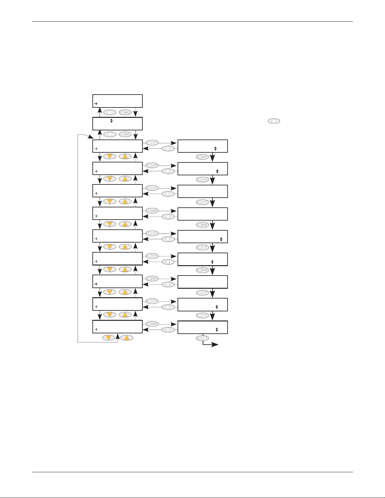
EPOWER CONTROLLER USER GUIDE
0
9999
0
Use up/down arrows to select Counter number, then Enter. Use return
key one or more times from within menu to return to this page
Shows whether ripple carry is
active (On) or not (Off).
‘Yes’ if up counter has exceeded target. OR if down counter has reached
zero. Otherwise ‘No’.
Use up/down arrows to change state of
clock. (Counter increments or decrements on 0 to 1 Clock transition)
Target value for count-up counters, or
starting value for count-down counters.
The current value of the counter.
Use up/down arrows to select ‘Yes’ to carry
out counter reset.
Use up/down arrows to clear the overflow ‘flag’.
Back to ‘Enable’
Use up/down arrows to set count
direction as ‘Up’ or ‘Down’.
Use up/down arrows to enable or
disable the selected counter
CONF
Count
Count N
Enable
Count N
Enable
Count N
Direction
Count N
Ripple C...
Count N
Overflow
Count N
Clock
Count N
Ta rg et
Count N
Count
Count N
Reset
Count N
Clear Ov...
Enable
Direction
Ripple Carry
Overflow
Clock
Ta rg et
Count
Reset
Clear Overflow
6.8 COUNTER MENU
The counter output is a 32-bit integer the value of which is recalculated every sample period. When a clock
state change from 0 (false) to 1 (true) is detected the counter value is incremented if the count direction is
‘up’ or decremented if the direction is ‘down’.
At reset, the counter value is set to 0 for count up counters or to the ‘Target’ value for count down counters.
6.8.1 Counter configuration menu
Enable The counter responds to clock transitions when enabled; the count is frozen when
Direction Select up or down as the direction of count. Up counters start at (and are reset to)
Ripple Carry The Ripple carry output of one counter can act as the enabling input for the next
Overflow Overflow becomes ‘true’ when the value of the counter is either zero (for count down
Clock The counter increments or decrements on a positive going edge (0 to 1; False to
disabled.
Figure 6.8.1 Counter menu
zero; down counters start from (and are reset to) the Target value (below)
counter in a cascade. Ripple carry is set ‘true’ when the counter is enabled and its
value is either zero (for count down timers) or equal to the Target value (count up
counters).
timers) or equal to the Target value (count up counters).
true).
HA179769
Page 78 Issue 11 Dec 15
Page 81
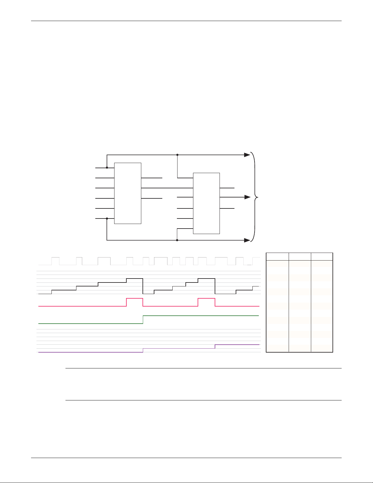
EPOWER CONTROLLER USER GUIDE
0
1
2
3
4
5
6
7
8
9
10
11
12
0
0
0
0
0
1
1
1
1
1
2
2
2
0
1
2
3
4
0
1
2
3
4
0
1
2
0
1
2
123 456789101112
0
1
2
3
4
0
1
2
3
4
0
1
2
Clock
Count 2
Count 1
Clock
Count 1
(Target = 4)
Ripple/Carry 1
Overflow 1
Count 2
To furth er
counters
Counter 2
Counter 1
Counts the number of
times Counter 1 target is exceeded
Counts clock rising edges
Clock
Clock
Enable
(high= enabled)
Direction
Tar ge t
Reset
(high= reset values)
Clear overflow
Clear overflow
(High = Clear overflow flag)
Clear overflow
Reset
Target
Direction
Enable
Overflow 1
Ripple/carry 1
Count 1
Count 2
Ripple/carry
Overflow
Clear overflow
Clock
6.8 COUNTER MENU (Cont.)
Target Up counters: Start at zero and count towards the Target value. When this value is
reached, Overflow and Ripple-carry are set true (value = 1).
Down counters: Start at the Target value and count towards zero. When zero is
reached, Overflow and Ripple-carry are set true (value = 1).
Count The current value of the counter. This is a 32-bit integer which accumulates clock
transitions. Minimum value is zero.
Reset Resets up-counters to zero or down-counters to the Target value. Reset also sets
Overflow to False (i.e. Overflow = 0)
Clear Overflow Sets Overflow to False (i.e. Overflow = 0)
6.8.2 Cascading counters
As implied above, it is possible to ‘wire’ counters in cascade mode. Details for an ‘up’ counter are shown in
figure 6.8.2, below. Down counter configuration is similar.
Note: Counter 2 above counts the number of times that Counter 1 target is exceeded. By
permanently enabling counter 2, and wiring counter 1 ‘Ripple Carry’ output to counter 2 ‘Clock’
Figure 6.8.2 Cascading up counters
input (replacing the connection to the clock pulse stream), counter 2 will indicate the number of
times counter 1 target is reached, rather than exceeded.
HA179769
Issue 11 Dec 15 Page 79
Page 82
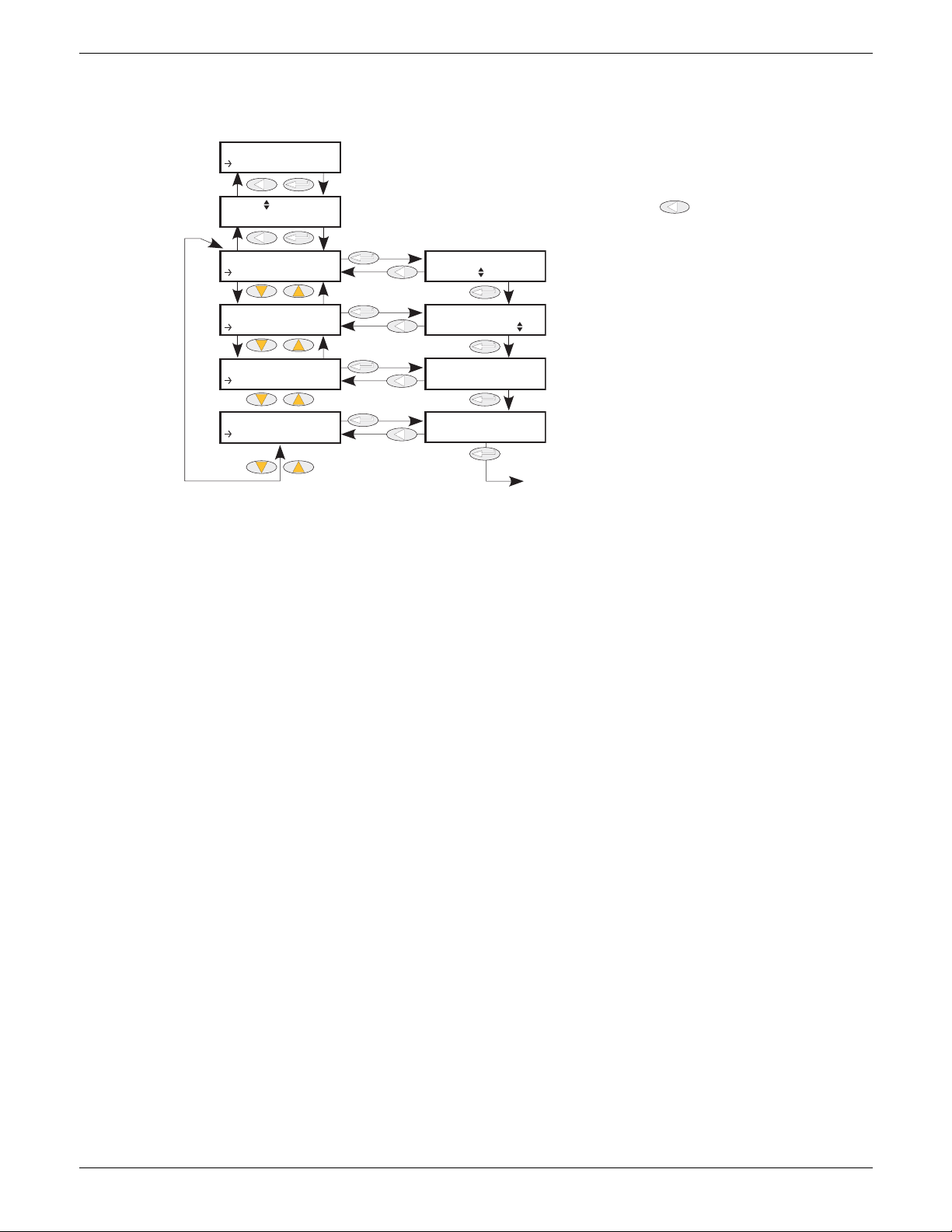
6.9 DIGITAL I/O MENU
0
0
Use up/down arrows to select Digital I/O number, then Enter. Use return [rtn
key one or more times from within menu to return to this page
Use up/down arrows to
select IP Contact, IPVolts
(Input volts) or OP (Digital
Use up/down arrows to select Yes
or No (to invert the signal or not,
respectively).
Desired output value, or the state of
the input (see text for further details).
Sense of the output (0 or 1), or the
electrical input at the terminals (see
text for further details).
Back to ‘Type’
CONF
Control
Digital N
Digital N
Ty pe
Digital N
Invert
Digital N
PV
Digital N
Meas Val
Ty pe
Invert
PV
Meas Val
IPContac
No
Digital I/O configuration.
EPOWER CONTROLLER USER GUIDE
Figure 6.9 Digital I/O menu
Type Selects I/O type: Logic Input, IPContact or digital output. For pinout details, see
figure 2.2.1c.
Invert Sets the inversion status to ‘No’ or ‘Yes’. For inputs, Yes inverts the input; for outputs,
Yes inverts the output measured value with respect to the input PV.
MeasVal For inputs, this shows the value measured at the instrument terminals, in electrical
units. For outputs, this shows 1 or 0 according as the output is high or low.
PV For inputs, this is the current state of the input, after any inversion has been applied.
For outputs, this is the desired output value (before any inversion is applied).
Page 80 Issue 11 Dec 15
HA179769
Page 83
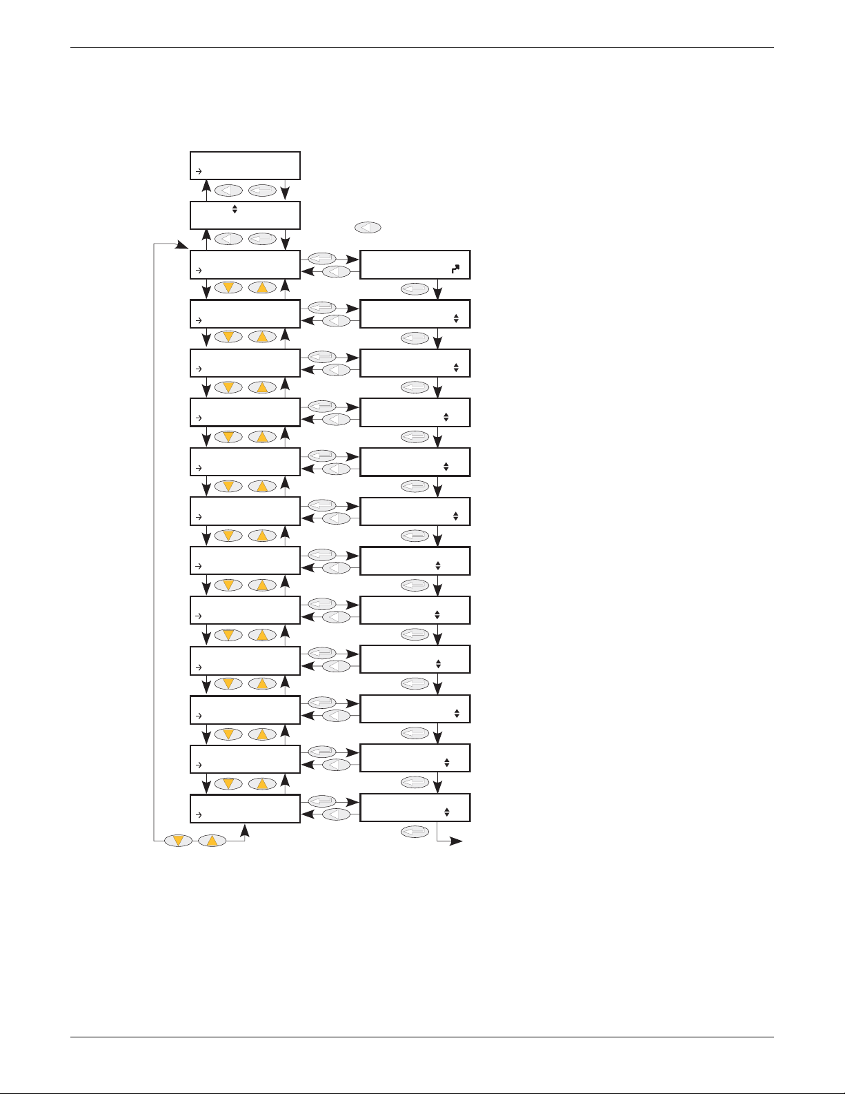
EPOWER CONTROLLER USER GUIDE
Use up/down arrows to select energy number, then Enter.
Use return key one or more times from within menu to return to
this page
Shows the instantaneous measured power.
Normally wired to Network Meas.P parameter.
Does not appear for the Global Energy Counter.
1 = Output fleetingly reset to zero; 0 = Output totalises.
(Resetting the global counter resets all Energy counters.)
1 = Output frozen at current value
0 = Output totalises.
(Holding the global counter holds all Energy counters.)
Energy consumed by this network since reset
Global energy consumption (this network).
The parameter value is not resettable
0 = No pulse output
1 = Pulse output enabled
Units scaling for this Network.
Select ‘1Wh’, ‘10Wh’, ‘100Wh’, ‘1kWh’, ‘10kWh’,
‘100kWh’, ‘1MWh’, ‘10MWh’, ‘100MWh’, ‘1GWh’
As above, but for Global consumption value
Pulse length scaling. Select ‘Disable’, ‘1Wh’, ‘10Wh’,
‘100Wh’, ‘1kWh’, ‘10kWh’, ‘100kWh’, ‘1MWh’
Minimum pulse length in ms
Valid entries 0 to 32000 inclusive
‘Global’ = This is the global counter
‘No’ = This is a network counter
‘No’ = use power scaling configured in UsrUnit (or TotUnit).
‘Yes’ = Autoscale the power display
Back to ‘Input’
(or to ‘Reset’ for Global Counter)
CONF
Energy
Energy N
Input
Energy N
Input
Energy N
Reset
Energy N
Hold
Energy N
UsrEnergy
Energy N
To tE ne r gy
Energy N
Pulse
Energy N
UsrUnit
Energy N
To tU n it
Energy N
PulseS ca...
Energy N
PulseLen
Energy N
IsGlobal
Energy N
AutoScale
Input
Reset
Hold
UsrEnergy
To tE ne r gy
Pulse
UsrUnit
To tU n it
PulseScale
PulseLen
IsGlobal
AutoScale
No
No
6.10 ENERGY
Provides a number of energy counters to totalise consumed energy. The value(s) can be displayed at the
driver module front panel (using iTools User Pages), and at the remote panel, if fitted. The power consumed
can be displayed in one of number of units, ranging from W to GW. Figure 6.10 shows the menu.
0
0
0
0.0
0.0
0
1Wh
1Wh
1Wh
0
Figure 6.10 Energy counter menu
HA179769
Issue 11 Dec 15 Page 81
Page 84

EPOWER CONTROLLER USER GUIDE
6.10.1 Energy counter parameters
Input Shows the instantaneous power input from the measuring source. Normally wired to
the Meas.P output of a Network block. Does not appear for the Global Energy
Counter (see ‘IsGlobal’, below).
Reset 1 = Energy counter output goes to zero and immediately starts accumulating.
0 = Energy counter not reset.
If the Global Energy counter is reset, it resets all other Energy counters (see
‘IsGlobal’, below).
Hold 1 = Hold output value. This freezes the output value for the block at the current value.
The input continues to be totalised, so when the Hold input returns to 0, the output
value is instantaneously updated to the new current value.
0 = output value is not held, and represents the current accumulated Energy value.
If the Global Energy counter is held, all other Energy counters are held as well (see
‘IsGlobal’, below).
UsrEnergy Shows the current value for the selected Energy Counter block. If this is the global
counter, this value is the sum of the energy values of all those networks being
totalised.
TotEnergy Shows the total energy value for the relevant network. Not reset by ‘Reset’ above.
Pulse This enables a pulse output which causes a pulse to be generated at a specified
number of watt-hours (1, 10, 100kW-h or 1MW-h). The length of the pulse and a
scaling factor can be entered, as described below.
UsrUnit Allows a scaling units value to be entered for the energy display. Selectable as ‘1Wh’,
‘10Wh’, ‘100Wh’, ‘1kWh’, ‘10kWh’, ‘100kWh’, ‘1MWh’, ‘10MWh’, ‘100MWh’ or ‘1GWh’.
TotUnit As ‘UsrUnit’, above, but for the total energy counter.
PulseScale One pulse is generated every ‘n’ Watt-hours, where ‘n’ can be selected as 1, 10, 100,
1k, 10k, 100k, 1M Watt-hours. This value, and that of Pulse Len(gth) must be chosen
to suit the application, such that the next pulse is not requested before the previous
one is finished. (In such a case, the PulseScale factor is automatically increased.)
PulseLen* Select pulse length between 0 and 32000 ms. The actual pulse length is rounded to
the next longest multiple of 1/2 the supply frequency. Thus, for a 50Hz system
(multiple = 10ms) pulse length entries of 1 to 10 will result in a pulse length of 10ms.
For entries of 11 to 20 the pulse length will be 20ms, and so on. This value, and that
of Pulse Scale must be chosen to suit the application, such that the next pulse is not
requested before the previous one is finished. (In such a case, the PulseScale factor is
automatically increased.)
IsGlobal One (only) of the Energy blocks can be defined as being ‘Global’. This means that it
sums the values of all the other Energy counters. The block ‘input’ is disabled. The
‘IsGlobal’ parameter becomes non-editable (set to ‘No’) for all other Energy counter
blocks. If the Global energy Counter is held or reset, all other counters are held and
reset as well.
‘No’ = This counter is not the Global counter.
‘Global’ = this counter is the Global counter.
Autoscale No = Use UsrUnit and TotUnit settings.
Yes = Autoscale power value display. Table 6.10.1 shows the breakpoints.
* Note: due to the computing time required, the pulse-length may vary according to circumstance.
For example, if a 20ms pulse is selected, the actual pulse length may be a mixture of 20ms and 30
ms pulses.
HA179769
Page 82 Issue 11 Dec 15
Page 85

EPOWER CONTROLLER USER GUIDE
6.10.1 ENERGY COUNTER PARAMETERS (Cont.)
Power Range (Watt-hours) Scaler value
0
65,535
65,535,000
655,350,000
6,553,500,000
65,535,000,000
655,350,000,000
6,553,500,000,000
Table 6.10.1 Autoscale breakpoints
to 65,535
to 65,535,000
to 655,350,000
to 6,553,500,000
to 65,535,000,000
to 655,350,000,000
to 6,553,500,000,000
upwards
1
1k
10k
100k
1M
10M
100M
1G
6.10.2 Resolution
The resolution of the stored energy value varies according to the totalised value, as shown in table 6.10.2
below. For example, for stored values between 33,554,432 watt-hours and 67,108,863 watt-hours, the value
increases in 4 watt-hour increments.
Power Range (Watt-hours)
0
16,777,216
33,554,432
67,108,864
134,217,728
268,435,456
536,870,912
1,073,741,824
2,147,483,648
4,294,967,296
8,589,934,592
to 16,777,215
to 33,554,431
to 67,108,863
to 134,217,727
to 268,435,455
to 536,870,911
to 1,073,741,824
to 2,147,483,647
to 4,294,967,295
to 8,589,934,591
to 17,179,869,183
Resolutio
n (W-h)
1
2
4
8
16
32
64
128
256
512
1,024
Table 6.10.2 Energy counter resolution
17,179,869,184
34,359,738,368
68,719,476,736
137,438,953,472
274,877,906,944
549,755,813,888
1,099,511,627,776
2,199,023,255,552
4,398,046,511,104
8,796,093,022,208
Power Range (Watt-hours)
to 34,359,738,367
to 68,719,476,735
to 137,438,953,471
to 274,877,906,943
to 549,755,813,887
to 1,099,511,627,775
to 2,199,023,255,551
to 4,398,046,511,103
to 8,796,093,022,207
to 17,592,186,044,415
6.11 EVENT LOG MENU
This topic is identical with the Event log in the User/Operator menu, and is described in section 5.2.2.
Resolution
(W-h)
2,048
4,096
8,192
16,384
32,768
65,536
131,072
262,144
524.288
1,048,576
HA179769
Issue 11 Dec 15 Page 83
Page 86
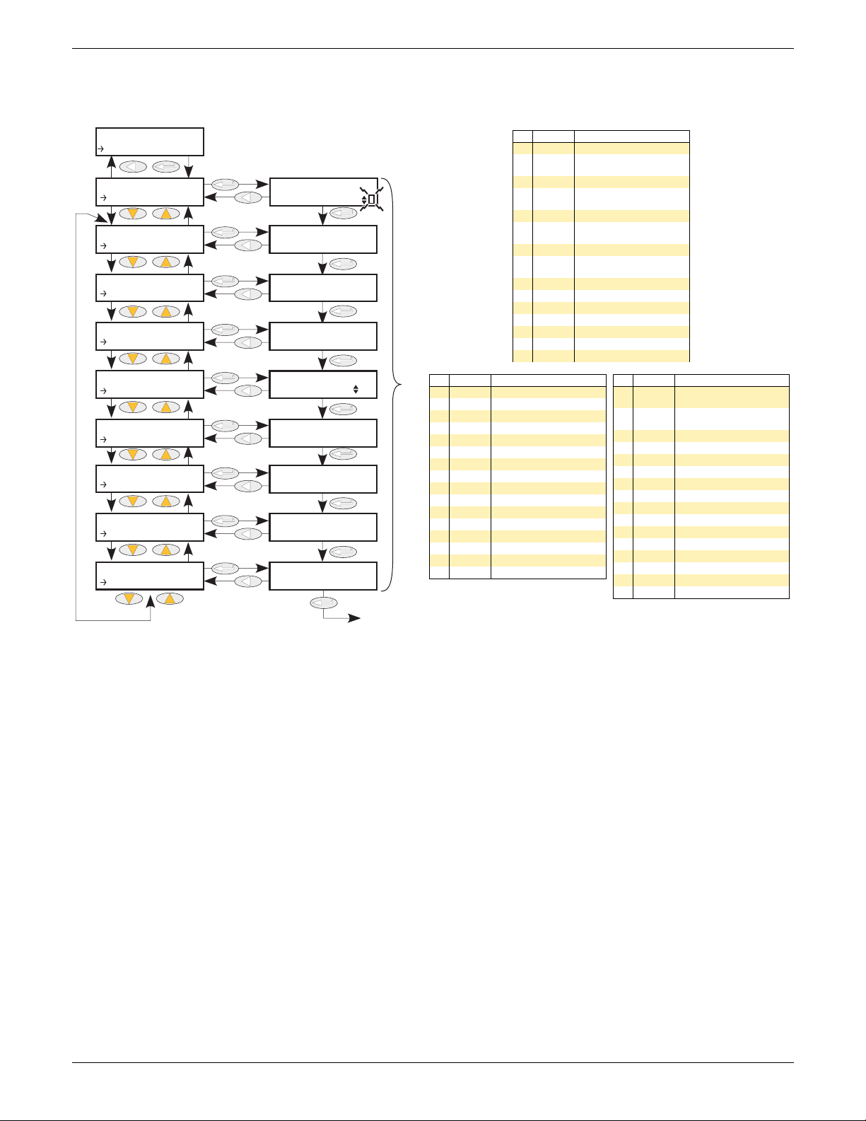
EPOWER CONTROLLER USER GUIDE
See text for details
Bit Value Description
0 1 Network 1 not firing
12
Network 1 not synchronized
2 4 Network 2 not firing
38
Network 2 not synchronized
4 16 Network 3 not firing
532
Network 3 not synchronized
6 64 Network 4 not firing
7 128
Network 4 not synchro-
nized
8 256 Strategy in standby mode
9 512 Strategy in Telemetry mode
10 1024 Reserved
11 2048 Reserved
12 4096 Reserved
13 8192 Reserved
14 16384 Reserved
Bit Value Description
0 1 Missing Mains
1 2 Thyristor short circuit
2 4 Open Thyristor
38Fuse blown
4 16 Over temp
5 32 Network Dips
6 64 Frequency fault
7 128 PB24V fault
8 256 Total Load Failure
9 512 Chop Off
10 1024 Partial Load Failure
11 2048 Partial Load Unbalance
12 4096 Vo lt fault
13 8192 Pre Temp
14 16384 Over current
15 32768 Power Module wdog fault
Table 6.12b
Alarm Status 1 word
Back to
Global Ack
Bit Value Description
0 1
Power Module Comms
error
12
Pwr Module Comms time-
out
2 4 Closed Loop
3 8 Transfer active
4 16 Limit active
5 32 PLM Pr over Ps fault
6 64 Output fault
7 128 LTC Fuse
8 256 LT C Te mp
9 512 Reserved
10 1024 Re served
11 2048 Reserved
12 4096 Re served
13 8192 Reserved
14 16384 Re served
15 32768 Reserved
Table 6.12c
Alarm Status 2 word
CONF
Faultdet
Faultdet
Global A...
Faultdet
Any Alarm
Faultdet
Network...
Faultdet
Fuse Ala...
Faultdet
Global D...
Faultdet
Strat St...
Faultdet
Watchdog...
Faultdet
Alarm St...
Faultdet
Alm St...
Global Ack
Any Alarm
Network Alarm
Fuse Alarm
Global Disable
Strat Status
Watchdog...
Alarm Status 1
Alarm Status 2
Active
No
Inactive
Inactive
Active
6.12 FAULT DETECTION MENU
This manages Alarm logging and provides an interface for the General Alarm Acknowledgement
259
8209
256
Figure 6.12 Fault detect menu
Global Ack Performs a global acknowledgement of alarms. Latched alarms are cleared if their
trigger sources are no longer in an alarm state.
Any Alarm ‘Active’ indicates that there is one or more System, Process or ‘Chop Off’ alarm active.
If the relevant alarms are enabled, System alarms and Chop Off alarms always cause
the power module to stop firing. Process alarms can also be configured to prevent
firing in ‘Alarm stop’.
Network Alarm Indicates that a process alarm has occurred in one or more Power Modules.
Fuse Alarm Indicates that a fuse has blown in one or more Network blocks.
Global Disable Allows the user to disable/enable all alarms.
StratStatus A coded status word giving strategy information as shown in table 6.12a.
Watchdog Watchdog relay status (Active or Inactive). The watchdog relay is active (non-
Alarm Status 1/2 Two 16-bit words containing alarm status information as shown in tables 6.12b and
energised) under fault conditions.
6.12c respectively.
Page 84 Issue 11 Dec 15
HA179769
Page 87
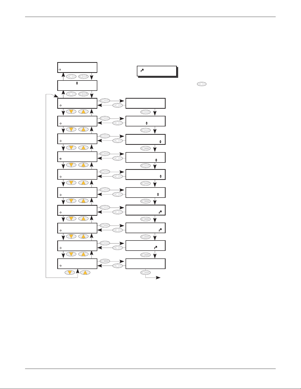
EPOWER CONTROLLER USER GUIDE
Use up/down arrows to select Firing op number, then Enter. Use return
key one or more times from within menu to return to this page
Displays the active firing mode of the control
strategy as one of: IHC, Burst, PA or No Mode.
Select ‘Resistive’ or TxFormer’ (transformer).
Safety Ramp duration, applied at startup, in mains periods, from 0 to 255. The ramp is from 0 to the target
phase angle, or from 0 to 100% for burst firing.
Use up/down arrows to select soft-start duration in mains 1/2 cycles.
Use up/down arrows to select soft-stop
duration in mains 1/2 cycles.
For transformer loads, use the up/down arrows
to select delayed trigger phase angle between
0 to 90 degrees
Enable/disable the Firing output block. Enable value must be non-zero.
Displays the input power demand value that
the firing must deliver.
Displays the phase angle reduction factor, in %, used
in Burst Firing. If this value is below 100, the unit delivers a burst of phase angle. Can be used to perform
threshold current limting in burst firing.
Displays the safety ramp status
Back to Mode
= wired input
CONF
Firing OP
Firing OP N
Mode
Firing OP N
Mode
Firing OP N
Load Type
Firing OP N
Safety R...
Firing OP N
Soft Sta...
Firing OP N
Soft Stop
Firing OP N
Delayed...
Firing OP N
Enable
Firing OP N
In
Firing OP N
PA L im it
Firing OP N
Ramp Sta...
Mode
Load Type
Safety Ramp
Soft Start
Soft Stop
Delayed Trigger
Enable
In
PA Lim it
Ramp Status
Logic
Resistive
Off
Ramping
6.13 FIRING OUTPUT MENU
This forms the link between the control strategy and the physical load. Configuration includes Firing mode,
Network Type and the type of Load coupling. This block also supplies Phase-Angle Ramp (Soft start) and
Safety Ramp.
In Engineer level, these items are mostly Read only (i.e. their values cannot be edited).
0
Mode Displays the current firing mode as Intelligent half cycle (IHC), Burst firing, Phase
1
85
Figure 6.13a Configuration firing Output
0
0
100
angle firing or no mode. Configured in the ‘Modultr’, menu described below.
Load Type Allows the load type to be selected as ‘Resistive’ or ‘Transformer’. For Load type =
Resistive, the load must be connected directly to the power module and only
resistive loads may be so connected. For Load Type = Transformer, the load is
connected to the power module via a transformer, and may be resistive or reactive.
HA179769
Issue 11 Dec 15 Page 85
Page 88
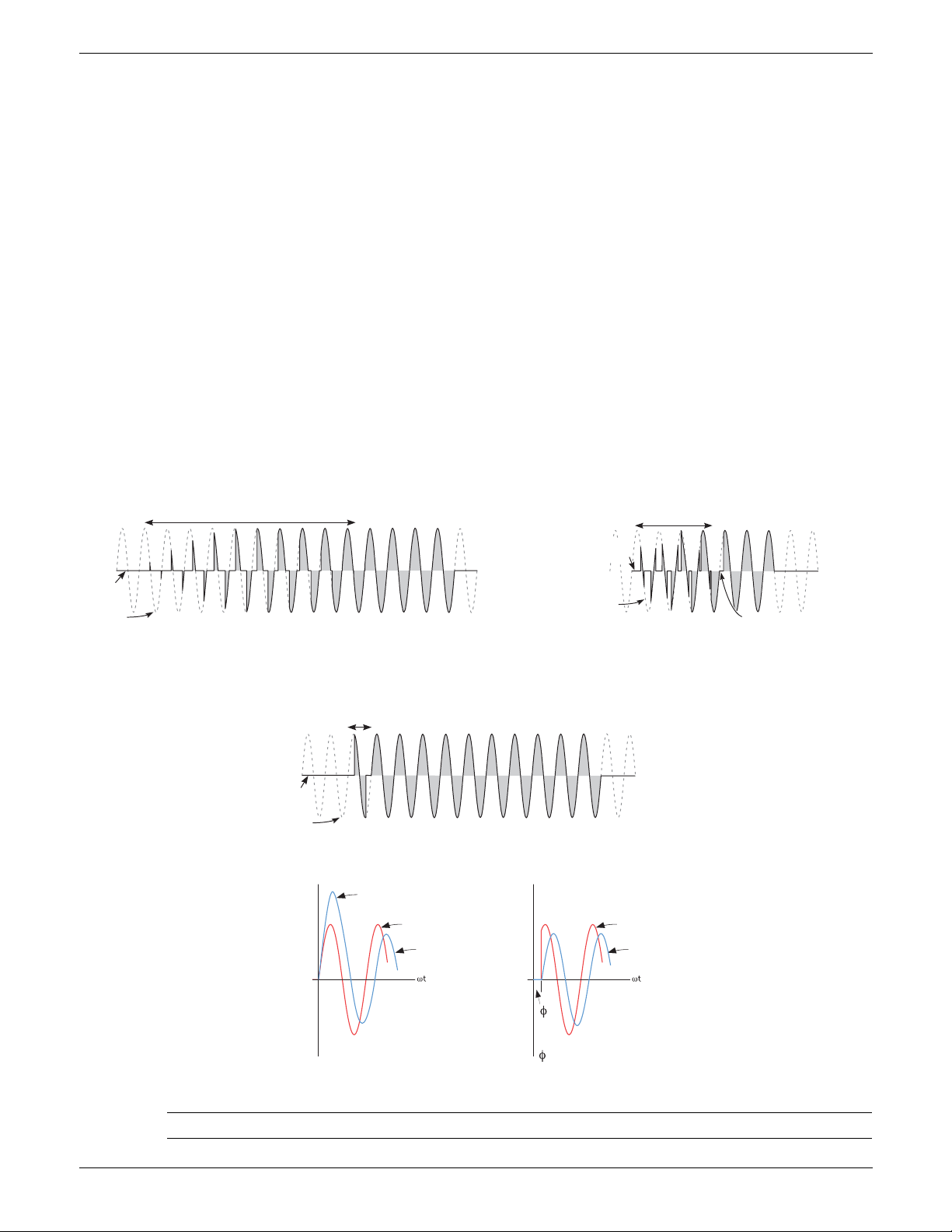
EPOWER CONTROLLER USER GUIDE
Safety Ramp (10 cycles)
Safety (Magnetisation) Ramp
(4 cycles)
Output
voltage
Line
supply
Line
supply
Output
voltage
Delayed trigger angle
Resistive load
Inductive load
Soft start = 2
Output
voltage
Line
supply
0 0
High current transient
Load voltage
Load current
Switch at zero volts
Load voltage
Load current
Switch at zero current
6.13 FIRING OUTPUT (Cont.)
Safety Ramp Displays the safety ramp duration, in supply voltage cycles (0 to 255), to be applied
at startup. The ramp is either a phase angle ramp from zero to the requested target
phase angle or, for Burst Firing, from 0 to 100%. See figure 6.13b. Safety Ramp is not
applicable to Half cycle Mode.
Soft Start For Burst Firing only, this is the soft start duration, in supply voltage 1/2 cycles,
applying a phase angle ramp at the beginning of each on period. (Figure 6.13c).
Soft Stop In Burst Firing, the soft stop duration, in supply voltage 1/2 cycles, applying a phase
angle ramp at the end of each on period.
Delayed Trigger Appears only if Mode = Burst, Soft Start = Off, and Load Type = TxFormer. Delayed
Trigger specifies the triggering delay, in phase angle, when delivering power into a
transformer load. Used to ensure that the thyristor is fired when the current is zero.
Configurable between 0 and 90 degrees inclusive. See figure 6.13d.
Enable Enables/disables firing. Must be wired to a non-zero value to enable firing (typically a
digital input).
In Displays the input power demand value that the power module is to deliver.
PA Limit Phase angle limit. This is a phase angle reduction factor used in Burst Firing. If lower
than 100% the power module will deliver a burst of phase angle firing. Used,
typically, to perform threshold current limiting in Burst Firing.
Ramp Status Displays the safety ramp status as ‘Ramping’ or ‘Finished’.
Figure 6.13b Safety ramp (burst firing) examples
Figure 6.13c Soft start example
Figure 6.13d Delayed trigger definition
Note: Waveforms have been idealised for clarity
Page 86 Issue 11 Dec 15
HA179769
Page 89
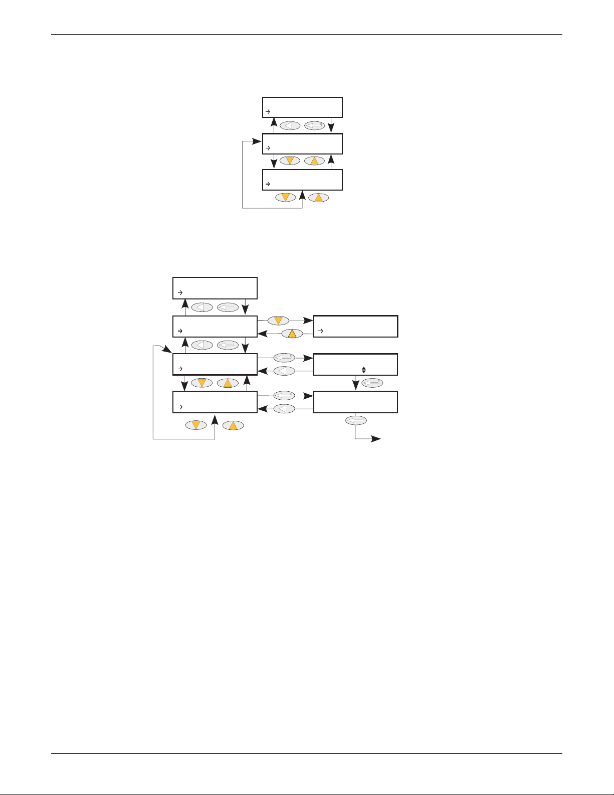
EPOWER CONTROLLER USER GUIDE
See figure 6.14.1
See figure 6.14.2
CONF
Instr
Instr
Display
Instr
Config
Use up/down arrows to
select display language
Displays unit’s serial number (read only)
See figure 6.14.2 for Config menu
Back to ‘Select Language’
CONF
Instr
Instr
Display
Instr
Config
Display
Select L...
Display
Serial N...
Select Language
English
Serial Num
6.14 INSTRUMENT MENU
Allows the user to select the display language, and to view the unit’s Serial number and the current Network
configuration.
Figure 6.14 Instrument menu
6.14.1 Instrument Display parameters
Allows the user to select display language and to view the unit’s serial number.
0
Figure 6.14.1 Instrument Display submenu
Serial Num Read only. Displays the factory-set Serial number of the unit.
Select Language The up and down arrow keys are used to select the required language from English,
French, German or Italian. (Correct at time of writing - further languages may be
added during the life of this manual.)
HA179769
Issue 11 Dec 15 Page 87
Page 90
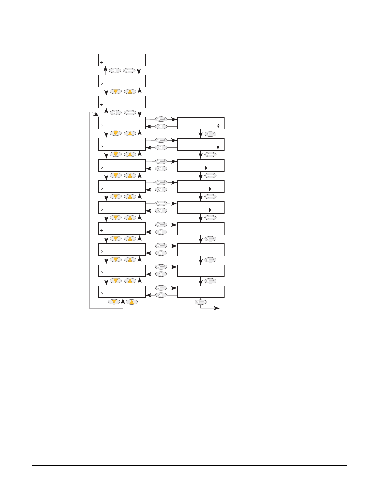
EPOWER CONTROLLER USER GUIDE
0
4
VN.N
VN.N
VN.N
VN.N
Use up/down arrows to enter the
number of power modules fitted.
(Confirmation required)
See figure 6.14.1
for Display menu
Use up/down arrows to
enter number of I/O modules fitted (if any).
Use up/down arrows to
select power network type
Use up/down arrows to
select coupling type
For 2 x 2-leg systems, use up/down
arrows to select coupling type for
second load.
Displays revision level of
power module 1
Displays revision level of
power module 2
Displays revision level of
power module 3
Displays revision level of
power module 4
Back to ‘Power Modules’
CONF
Instr
Instr
Display
Instr
Config
Config
Pow er M o. ..
Config
IO Modul...
Config
Network...
Config
Load Cou...
Config
Load 2 C...
Config
PwrMod1R...
Config
PwrMod2R...
Config
PwrMod3R...
Config
PwrMod4R...
Pow er M odules
IO Modules
Network Type
Load Coupling
Load 2 Coupling
PwrMod1Rev
PwrMod2Rev
PwrMod3Rev
PwrMod4Rev
2Phase
3Star
3Star
6.14.2 Instrument Config parameters
Allows the user access to the current power network configuration.
Power Modules Configures the number of power modules fitted. If left at zero, the system
IO Modules Specifies the number of optional I/O modules fitted. If left at zero, the system
Network Type Selects the type of network to be used, from 3 Phase, Single Phase or 2 Phase.
Load Coupling For a three-phase system this allows the user to select the wiring configuration from
automatically determines the number of modules fitted and sets the parameter
accordingly.
automatically determines the number of modules fitted and sets the parameter
accordingly.
Figure 6.14.2 Instrument Config submenu
3Star, 3Delta, 4Star or 6Delta. For a two-phase system, only 3Delta or 3Star is
Load 2 Coupling As Load Coupling, above, but for the second load in 2 x 2-leg systems.
PwrMod1Rev Shows the revision level of power module ‘1’.
PwrMod2Rev Shows the revision level of power module ‘2’.
PwrMod3Rev Shows the revision level of power module ‘3’.
PwrMod4Rev Shows the revision level of power module ‘4’.
selectable.
Page 88 Issue 11 Dec 15
HA179769
Page 91
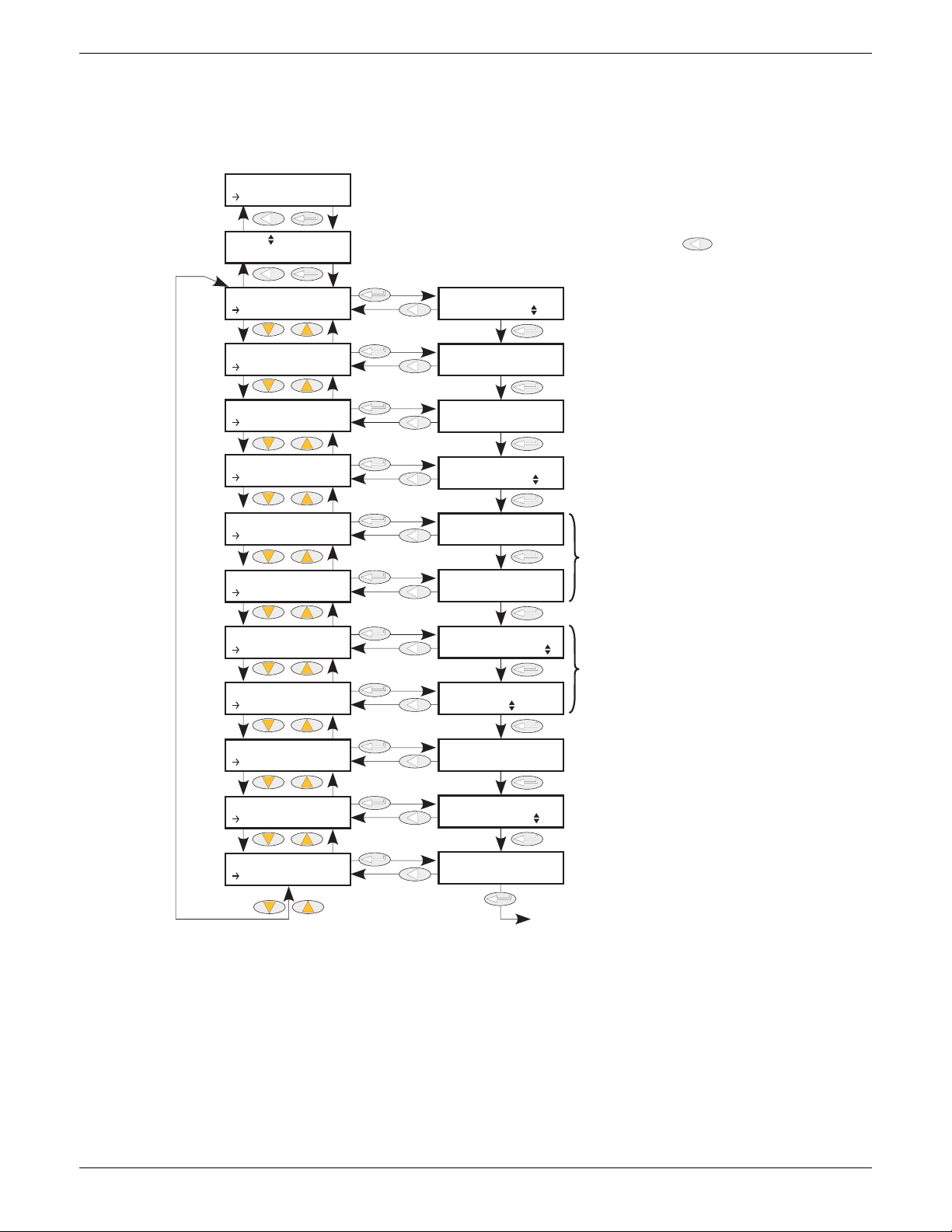
EPOWER CONTROLLER USER GUIDE
0.0
0.0
0.0
0.0
0
00:00.0
0
00:00.0
The parameter being monitored. Normally
wired to a parameter using iTools.
Use up/down arrows to select input monitor number, then Enter. Use return
key one or more times from within menu to return to this page
The maximum value reached by the parameter
since last reset
The minimum value reached by the parameter
since last reset
The trigger value for accumulating ‘Time
Above’ values
The total time (since last reset) that the parameter
value has spent above the threshold value, in
whole days plus hours and minutes
The total time that the parameter value may
spend above the threshold value before
triggering ‘Alarm out’.
Alarm out goes ‘True’ (on) if the Days above +
Time Above exceeds Alarm days + Alarm Time
Sets Max and Min values to zero.
Sets ‘Days Above’ and ‘Time Above’ values to zero.
The status of the parameter input
(Good or Bad).
Back to ‘In’
CONF
IPMon
IPMon N
In
IPMon N
In
IPMon N
Max
IPMon N
Min
IPMon N
Threshold
IPMon N
Days Abo...
IPMon N
Time Abo...
IPMon N
Alarm Da...
IPMon N
Alarm Ti...
IPMon N
Alarm Out
IPMon N
Reset
IPMon N
Status
In
Max
Min
Threshold
Days Above
Time Above
Alarm Days
Alarm Time
Alarm Out
Reset
Status
Good
No
Off
6.15 IP MONITOR MENU
This monitors a wired parameter and records its maximum value, minimum value and the cumulative time
that its value spends above a configurable threshold. An alarm can be set up to become active when the
time-over-threshold exceeds a further threshold.
Figure 6.15 IP Monitor menu
HA179769
Issue 11 Dec 15 Page 89
Page 92

EPOWER CONTROLLER USER GUIDE
6.15 IP MONITOR MENU (Cont.)
In The parameter to be monitored. Normally wired (using iTools) to a parameter, but a
numeric entry can be made for testing purposes.
Max The maximum value reached by the parameter since last reset.
Min The minimum value reached by the parameter since last reset
Threshold This value acts as a trigger for the ‘Time Above’ measurement.
Days above Shows how many complete days the parameter value has spent above the Threshold
value (continuously or intermittently) since last reset. The ‘Time Above’ value should
be added to ‘Days Above’ in order to find the total time.
Time Above Shows how many hours, minutes and tenths of minutes that the parameter value has
spent above the threshold value (continuously or intermittently) since last reset, or
since the last complete day. (once the value exceeds 23:59.9, it increments the ‘Days
Above’ value and resets itself to 00:00.0.) The ‘Time Above’ value should be added
to ‘Days Above’ in order to find the total time.
Alarm Days Together with ‘Alarm Time’ this defines a ‘total time above threshold’ value, which,
when exceeded, sets the Alarm out parameter ‘On’.
Alarm Time See ‘Alarm Days’ above.
Reset Resetting causes the Max. and Min. values to be set to the current value, sets the
‘Days Above’ value to zero, and the ‘Time Above’ value to 00:00.0.
Status Shows the status of the input parameter as either ‘Good’ or ‘Bad’.
HA179769
Page 90 Issue 11 Dec 15
Page 93
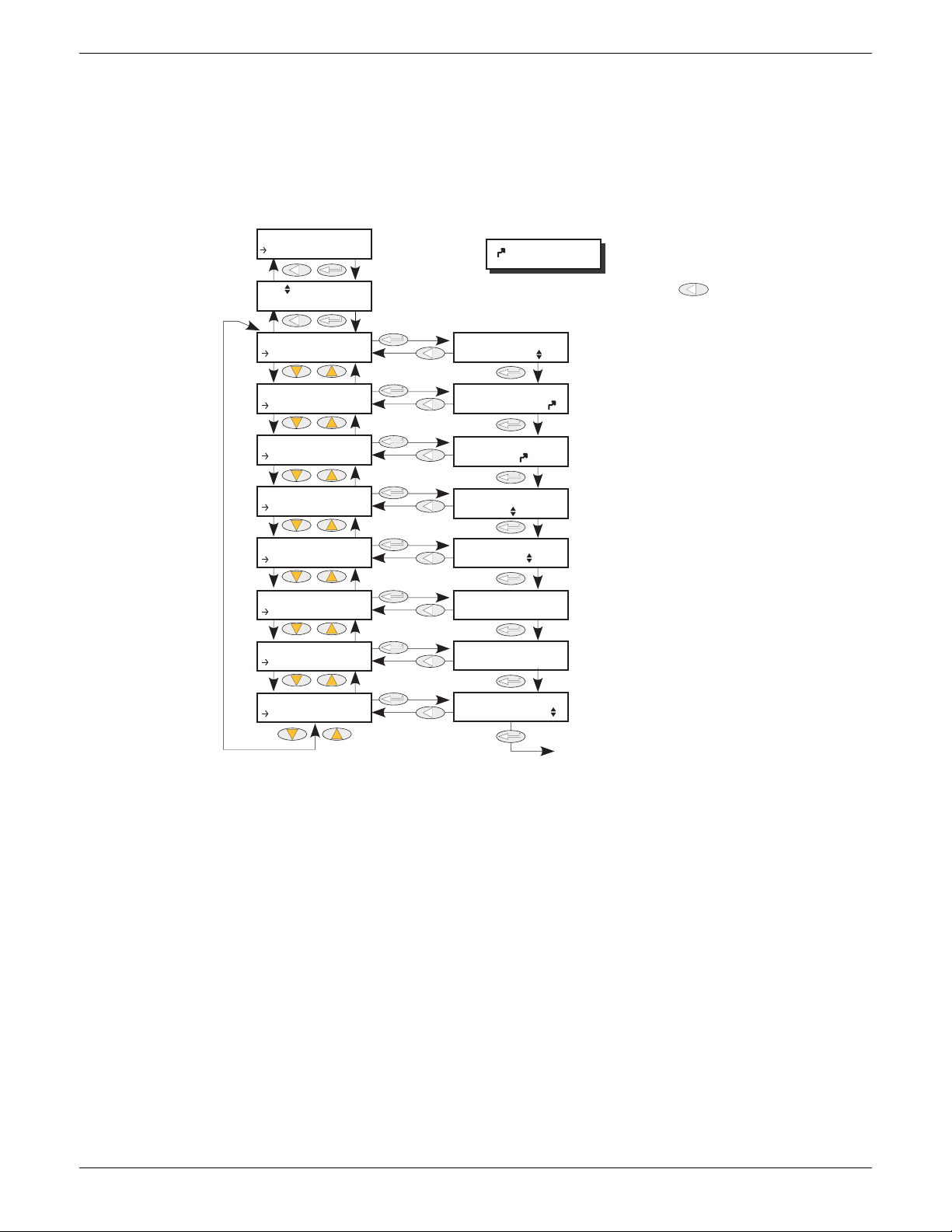
EPOWER CONTROLLER USER GUIDE
0.4900
0
0
Select operator as:
’OFF’, ‘AND’, ‘OR’, ‘XOR’, ‘LATCH’,
‘==’, ‘<>’, <,>’, ‘>=’, ‘<=’
Use up/down arrows to select Lgc2 number, then Enter. Use return key [rtn ke one or
more times from within menu to return to this page
Shows current value of input 1. If not wired,
allows a value to be entered.
Shows current value of input 2. If not wired,
allows a value to be entered.
Select ‘FalseBad’, ‘TrueBad’, ‘FalseGood’ or
‘TrueGood’ as fallback type.
Select ‘None’, ‘Input1’, ‘Input2’ or ‘Both’
for input inversion
Shows current value of the output
Shows current status of the output
Back to ‘Oper’
= wired input
CONF
Lgc2
Lgc2
N
Oper
Lgc2 N
Oper
Lgc2 N
Input1
Lgc2 N
Input2
Lgc2 N
Fall Type
Lgc2 N
Invert
Lgc2 N
Output
Lgc2 N
Status
Lgc2 N
Hyst
Oper
Input1
Input2
Fall Type
Invert
Output
Status
Hyst
Good
OFF
Off
None
FalseB ad
6.16 LGC2 (TWO INPUT LOGIC OPERATOR) MENU
This logic operator block provides a number of two-input logic operations. The output is always a ‘Boolean’
(logic 0 or 1) no matter whether the inputs are analogue or digital. For analogue inputs, any value below 0.5
is deemed to be logic 0 (off). A value equal to or greater than 0.5 is treated as a logic 1 (on).
Either input can be ‘inverted’ as a part of the configuration (that is, a high input is treated as a low input and
vice-versa.)
Figure 6.16 shows the LGC2 menu.
6.16.1 Lgc2 Parameters
Figure 6.16 LGC2 menu
Oper Allows the user to select a logic operation for the block. The descriptions below
Off No logic operation selected.
AND Output high if both inputs high, otherwise output is low.
OR Output high if either or both inputs high, otherwise output low.
XOR Output high if either (but not both) inputs high. Low if neither or both inputs high.
LATCH If i/p2 low, output latches next transition of i/p1. Value remains latched until i/p2
== Output high if both inputs are equal, otherwise output is low.
<> Output high if inputs are unequal. Output is low if both inputs are equal.
assume neither input is inverted. High = 1 or on; Low = 0 or off.
goes low, when output = i/p1 (see figure 6.16.1).
> Output high if i/p1 value greater than i/p2 value, otherwise output is low.
< Output high if i/p1 value less than i/p2 value, otherwise output is low.
>= Output high if i/p1 value is equal to or greater than i/p2 value, otherwise output is
low.
<= Output high if i/p1 value is less than or equal to i/p2 value, otherwise output is low.
HA179769
Issue 11 Dec 15 Page 91
Page 94
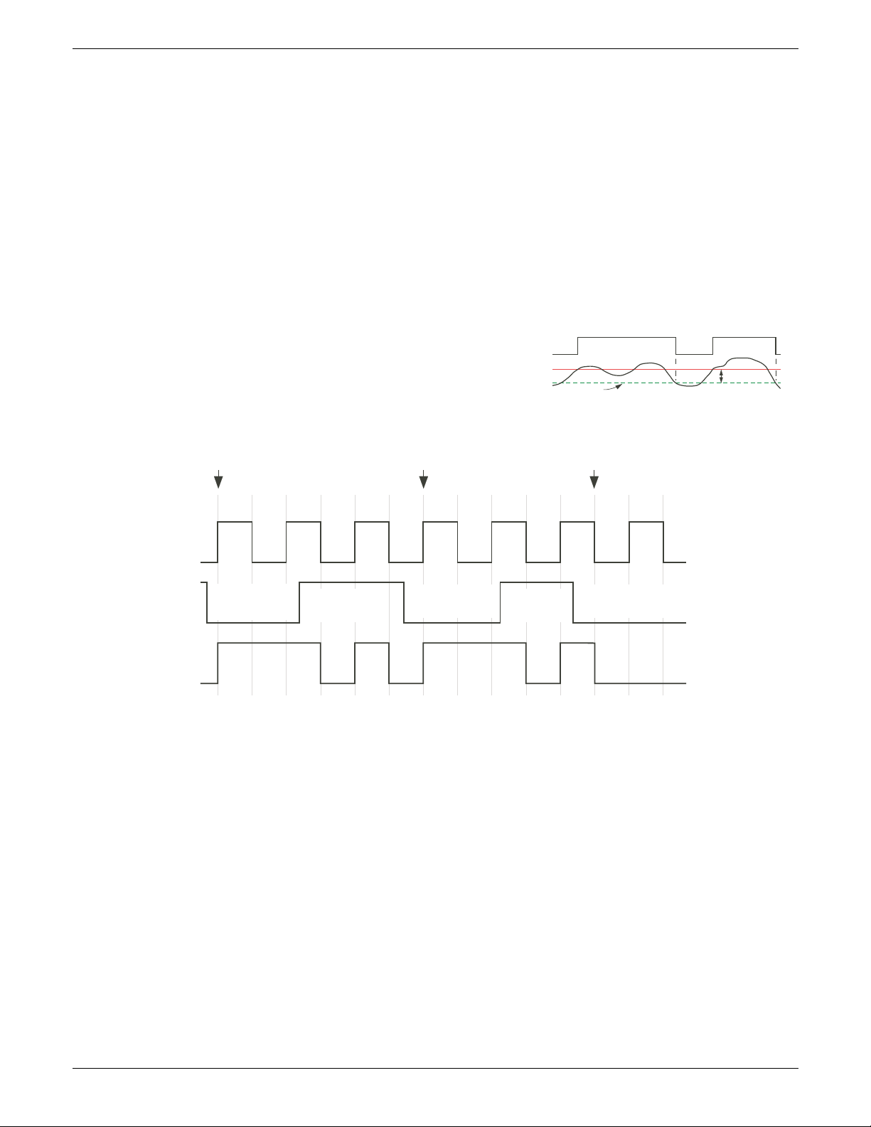
EPOWER CONTROLLER USER GUIDE
I/P2
I/P1
O/P
H
I/P1 > (I/P2-H) I/P1 > (I/P2-H)
Hysteresis
X XX
i/p 1
i/p 2
o/p
o/p latches first
transition of i/p1
o/p latches first
transition of i/p1
o/p latches first
transition of i/p1
o/p follows
i/p1
o/p follows
i/p1
When i/p2 goes low, o/p follows the next positive or negative transition of i/p 1 (points ‘X’) and
latches at this value until i/p2 goes high. When i/p2 is high, o/p follows i/p1.
6.16.1 LGC2 PARAMETERS (Cont.)
Input 1 If wired, shows the value of input 1; if not, allows the user to enter a value.
Input 2 If wired, shows the value of input 1; if not, allows the user to enter a value.
Fall type Allows a fallback type to be selected. This defines the output value and status
displays if the status of one or both inputs is ‘bad’.
FalseGood Output value displays ‘False’ ; Status displays ‘Good’
FalseBad Output value displays ‘False’ ; Status displays ‘Bad’
TrueGood Output value displays ‘True’ ; Status displays ‘Good’
TrueBad Output value displays ‘True’ ; Status displays ‘Bad’
Invert Allows none, either or both inputs to be inverted.
Output Shows the current output value
Status Shows the status of the output (‘Good’ or ‘Bad’).
Hysteresis For comparison operators only (e.g. >) this
allows a hysteresis value to be entered. For
example, if the operator is ‘>’ and hysteresis
is H, then the output goes high when input 1
exceeds input 2, and remains high until input
1 falls to a value less than (Input 2 - H). Not
applicable to the ‘==’ (equals) function.
Figure 6.16.1 Latch operation
Page 92 Issue 11 Dec 15
HA179769
Page 95
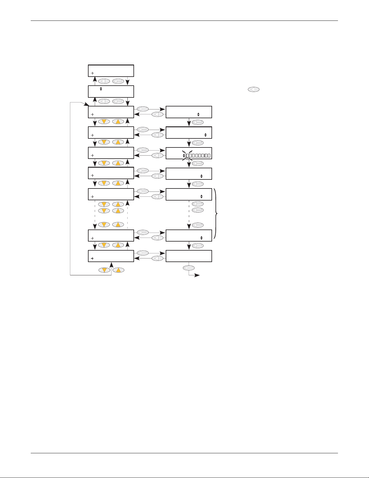
EPOWER CONTROLLER USER GUIDE
Select AND, OR, Exclusive OR or OFF.
Use up/down arrows to select Logic number, then Enter. Use return key [rtn
key] one or more times from within menu to return to this page
Select number of inputs from two to eight.
Use Enter key to move from input to input (current
selection flashes). Use up/down key to select
invert (solid yellow) or not for the current selection.
Final Enter quits Invert configuration.
No = Output not inverted
Yes = Output inverted
Input states 1 to N, where N is the number of inputs selected (two to eight inclusive).
The output status of the selected logic function.
Back to ‘Operation’
CONF
Lgc8
Lgc8 N
Operation
Lgc8 N
Operation
Lgc8 N
Number o...
Lgc8 N
Invert
Lgc8 N
Out Inve...
Lgc8 N
In1
Lgc8 N
In8
Lgc8 N
Out
Operation
Number of
Invert
Out Invert
In1
In8
Out
Off
Off
Off
No
AND
6.17 LGC8 (EIGHT-INPUT LOGIC OPERATOR) MENU
This allows between 2 and 8 inputs to be com bined using an AND , OR or E xclus ive OR (EXOR ) logi c func tion.
The inputs may be individually inverted, and the output can also be inverted, thus allowing the full range of
logic functions to be implemented.
8
8
1
Figure 6.17 Lgc8 Menu
Operation Allows selection of AND, OR or Exclusive OR functions (or OFF).
AND = output is high only if all inputs are high
OR = output is high if any or all inputs are high
XOR = output is high if an odd number of inputs are high, and low if an even number
Number of inputs Set the number of inputs to between two and eight inclusive. This number defines
Invert Between two and eight piano keys appear (according to the number of inputs
of inputs are high. Logically, a cascaded XOR function: (((((((In1 In 2) In 3) In
4).... In 8)
how many invert keys appear in ‘Invert’, and how many Input value pages appear.
selected) at the bottom line of the display, with the left-most one (input 1) flashing.
The up or down arrow can be used to select ‘invert’ for this input (key goes solid
yellow), and/or the ‘Enter’ key can be used to move to the next input. Once all the
inputs have been accessed, the final operation of the Enter key quits the Invert
configuration, and ‘output invert’ is entered.
Out Invert No = normal output; ‘Yes’ means that the output is inverted, allowing NAND and
NOR functions to be implemented.
In1 The state (on or off) of the first input
In2 onwards The state of the remaining inputs
Out The Output value of the function (i.e. On or Off)
HA179769
Issue 11 Dec 15 Page 93
Page 96
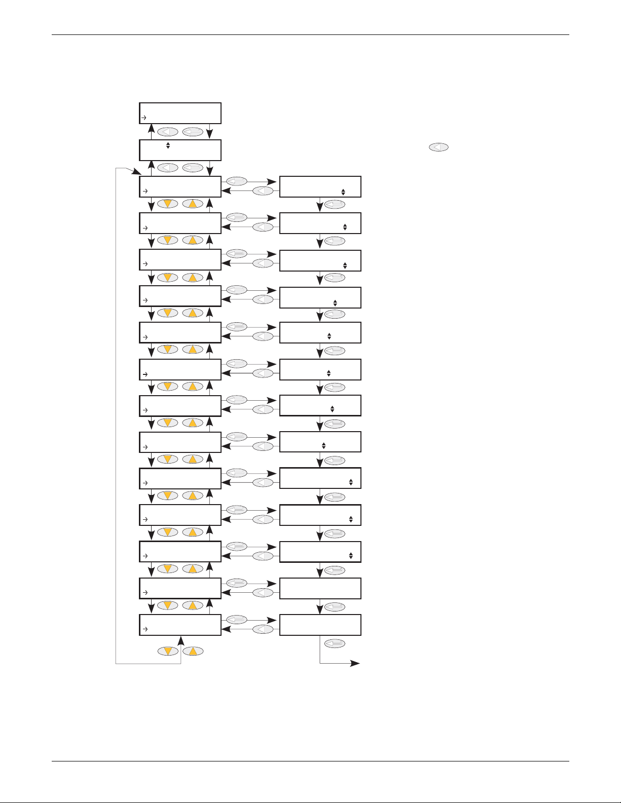
EPOWER CONTROLLER USER GUIDE
1.0
1.0
XXXXX
99999
0
0
-99999
0
0
Use the up/down keys to select required
maths function (see text for details).
Use up/down arrows to select Math2 number, then Enter. Use return key [rtn key]
one or more times from within menu to return to this page
Use the up/down keys to enter the scaling
factor to be applied to input 1
Use the up/down keys to enter the scaling
factor to be applied to input 2
Use the up/down arrows to select
output units (see text for details)
Use the up/down arrows to select the number
of decimal places for the output value
Use the up/down arrow keys to
enter the output low limit
Use the up/down arrow keys to
enter the output high limit
The state to which the output and status
parameters are forced under fault conditions. See text for details.
Specifies the value which the output takes
under fault conditions.
Input 1, normally wired to an input source.
Input 2, normally wired to an input source.
Displays the current output value
Displays ‘Good’ or ‘Bad’.
Back to ‘Operation’
CONF
Math2
Math2 N
Operation
Math2 N
Operation
Math2 N
Input1 S...
Math2 N
Input2 S...
Math2 N
Out Units
Math2 N
Out Reso...
Math2 N
Low Limit
Math2 N
High Lim...
Math2 N
Fall back
Math2 N
Fall back...
Math2 N
In1
Math2 N
In2
Math2 N
Out
Math2 N
Status
Operation
Input1 Scale
Input2 Scale
Out Units
Out Resolution
Low Limit
High Limit
Fallback
Fallback Value
In1
In2
Out
Status
Good
Off
None
Clip bad
6.18 MATH2 MENU
This feature allows a range of two-input mathematical functions to be performed. The available functions are
listed below.
Figure 6.18 Analogue maths functions menu
HA179769
Page 94 Issue 11 Dec 15
Page 97

EPOWER CONTROLLER USER GUIDE
6.18 MATH2 MENU (Cont.)
Note: For the sake of this description, ‘High’, ‘1’ and ‘True’ are synonymous, as are ‘Low’, ‘0’ and
‘False’.
Operation Defines the mathematical function to be applied to the inputs:
None No operation.
Add Adds input one to input two.
Sub Subtracts input two from input one.
Mul Multiplies inputs one and two together.
Div Divides input one by input two.
AbsDif The difference in value between inputs one and two, ignoring sign.
SelMax Output = the higher of inputs one and two.
SelMin Output = the lower of inputs one and two.
HotSwp Input one appears as the output for as long as input one is ‘good’. If input one
status is bad, input two appears as the output instead.
SmpHld Sample and Hold. The output follows input one, for as long as input two is high
(sample). When input two goes low (hold), the output is held, at the value current
when the output went low, until input two goes high again. Input two is normally
a digital value (low = 0 or high =1); when it is an analogue value, then any
positive non-zero value is interpreted as a high.
Powe r
Output = Input one raised to the power of input two (In1
one has the value 4.2, and the value of input two is 3, then output = 4.2
Sqrt The output is the square root of input one. Input two is not used.
Log Output = Log
Ln Output = Log
Exp
10 x
Output = e
Output = 10
(input one). (Log base 10). Input two is not used.
10
(input one). (Log base e). Input two is not used.
n
(input one)
. Input two is not used.
(input one)
. Input two is not used.
Select If the Select input is high, input two appears at the output; if the Select input is
low, input one appears at the output.
Input1 Scale The scaling factor to be applied to input one.
Input2 Scale The scaling factor to be applied to input two.
Out Units Allows the user to choose units for the output.
Out
Resolution
Use the up and down arrows to position the decimal point as required.
Low Limit The low limit for all inputs to the function and for the fallback value.
High Limit The high limit for all inputs to the function and for the fallback value.
Fallback The fallback strategy comes into play if the status of the input value is ‘Bad’, or if its value lies
outside the range (High limit- Low limit).
Fall Good: The output is set to the fallback value (below); output status is set to ‘Good’.
Fall Bad: The output is set to the fallback value (below); output status is set to ‘Bad’.
Clip Good: The output is set to the high or low limit as appropriate; output status is set to
‘Good’.
Clip bad: The output is set to the high or low limit as appropriate; output status is set to
‘Bad’.
DownScale: The output is set to the low limit and Status is set to ‘Bad’.
Upscale: The output is set to the high limit and Status is set to ‘Bad’.
Fallback
value
Allows the user to enter the value to which the output is set for Fallback = Fall Good, or Fall
Bad.
Select Appears only if Operation = Select. Allows input one or input two to be selected for output.
In1 Input one value (normally wired to an input source).
In2 Input two value (normally wired to an input source).
Out The output value resulting from the configured mathematical operation. If either input is ‘Bad’,
or if the result is out of range, the fallback strategy is adopted.
Status Indicates the status of the operation as ‘Good’ or ‘Bad’. Used to flag error conditions and can
be used as an interlock for other operations.
In2
). For example if input
3
= 74.09.
HA179769
Issue 11 Dec 15 Page 95
Page 98
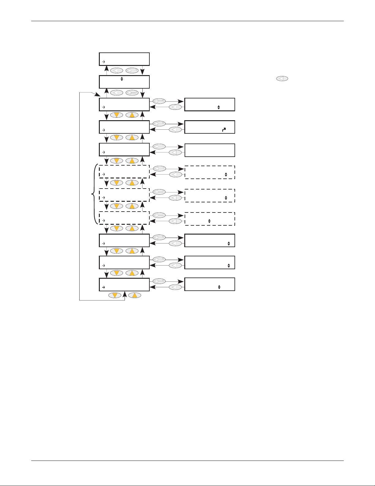
EPOWER CONTROLLER USER GUIDE
75
0.0
0.0
1
16
1
Allows modulation firing mode to be selected from:
‘Logic’, ‘PA’ (phase angle), ‘Half Cycle’, ‘BurstVar’ or
‘BurstFix’
Use up/down arrows to select modulator number, then Enter. Use return key [rtn key]
one or more times from within menu to return to this page
Input signal representing the required power
output
Modulator logical output for controlling
the power module(s). If mode = PA, this is a
phase angle demand.
Appears only for Mode = BurstVar.
Appears only for Mode = BurstFix
For Mode = Logic only, defines when the output from
the modulator block is to be stopped.
Half Cycle = stops on next zero crossing
Full Cycle = stops at next full cycle zero crossing
Use up/down arrows to select the
load management interface input.
Input fillter time in modulation periods.
0 = Filter disabled
Use up/down arrows to select:
Burst or Phase Angle
Mutually exclusive
CONF
Modultr
Modultr N
Mode
Modultr N
Mode
Modultr N
Input
Modultr N
Output
Modultr N
Min On
Modultr N
Cycle Ti...
Modultr N
Logic Mo...
Modultr N
LMIn
Modultr N
InFiltTi...
Modultr N
Switch PA
Mode
Input
Output
Min On time
Cycle Time
Logic Mode
LMIn
InFiltTime
Switch PA
Burst
Full cycle
Logic
6.19 MODULATOR MENU
This function implements the modulation type firing modes such as fixed and variable period modulation.
Mode Select the required firing mode from “Logic’, ‘PA’ (Phase angle) ‘Half cycle’, ‘BurstVar’
Input This is the value that the modulator is required to deliver.
(Burst firing - minimum on time) or ‘BurstFix’ (Burst firing - cycle time).
Figure 6.19 Modulator menu
Output The output logic signal controlling the power module on and off times, normally wired
Min on Time For Variable Period Modulation, this sets the minimum on time in supply voltage
to the input of the firing block. For Mode = Phase angle, this is a phase angle demand.
periods. At 50% demand from the modulator, Ton = Toff = Minimum on time, and Cycle
Cycle Time For Fixed Period Modulation, this is the cycle time in supply voltage periods.
Logic Mode For Logic Firing Modulation, Half cycle sets firing stop to the next zero crossing; Full
time is 2 x Minimum on time = Modulation period. The minimum off time is equal to
‘Min on time’.
cycle sets firing stop at the zero crossing of the next full cycle.
LMIn Load Management Interface input. Defines a connection from the modulator to a load
InFiltTime Modulator input filter time as a number of modulation periods. When set to zero, filter is
Switch PA Allows the user to impose Phase Angle firing, overriding the configured Burst Mode as
management channel (if fitted).
disabled.
displayed in ‘Mode’, above.
HA179769
Page 96 Issue 11 Dec 15
Page 99
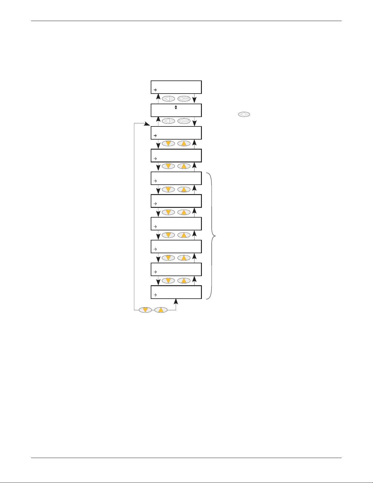
EPOWER CONTROLLER USER GUIDE
Use up/down arrows to select network number, then Enter.
Use return key one or more times from within menu to
return to this page
Figure 6.20.1
Figure 6.20.2
Figure 6.20.3
CONF
Network
Network N
Meas
Network N
Meas
Network N
Setup
Network N
AlmDis
Network N
AlmDet
Network N
AlmSig
Network N
AlmLat
Network N
AlmAck
Network N
AlmStop
6.20 NETWORK MENU
This identifies the type of electrical network to be controlled, and this, in turn defines how the network’s
electrical measurements are presented. The configuration is related to a power channel, not necessarily the
Power Module number. For a network of four single-phase units, four network blocks are required; for two
leg control of a three-phase network, two network blocks are used; for three-phase control of a single
network, one Network block is required.
Figure 6.20 Network menu
HA179769
Issue 11 Dec 15 Page 97
Page 100
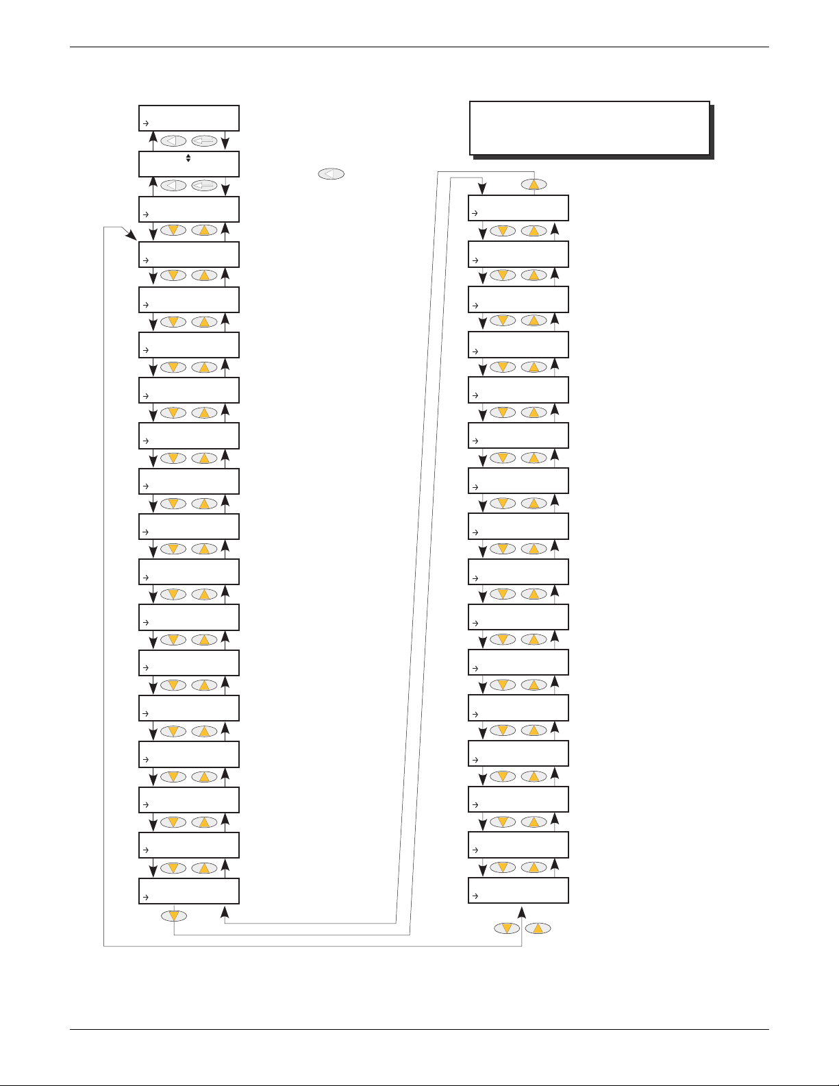
6.20.1 Meas submenu
Displays Mains frequency of the relevant power channel
Use up/down arrows to select network number, then Enter.
Use return key one or more times from within menu to
return to this page.
Displays Line voltage measurement
of primary unit (see text)
Displays 2nd phase Line voltage
Displays 3rd phase Line voltage
Displays Load RMS curent in primary
unit.
Displays 2nd phase Load curent
(RMS)
Displays 3rd phase Load curent
(RMS)
Displays the average of the RMS
current for three phase and two
leg systems
The main-period average value
of I2 used for I2 control.
For Burst firing only, the average
value of I2 taken over the duration of the burst period.
The maximum value out of I
2
, I22,
I32. Used in current limiting and
alarm strategies
The RMS value of I2 maximum
over one mains period
Displays load voltage of primary
power module (phase-to-phase or
phase-neutral according to setup).
Displays load voltage of 2nd phase
power module (phase-to-phase or
phase-neutral according to setup).
2nd and 3rd phase menu items appear
only if network type is two or three
phase respectively (section 6.20.2).
Displays the average of the RMS
voltage for three phase and two
leg systems
For Burst firing only, the average
value of V2 taken over the duration
of the burst period.
The main-period average value
of V2 used for V2 control.
The maximum value out of V
2
,
V2
2
, V32. Used in current limiting
and alarm strategies
The RMS value of V2 maximum over
the mains period. Used for voltage
limiting or voltage transfer.
Displays true power measurement for
the power network, over the modulation period.
Displays true power measurement for
the power network on the main period
in phase angle and in burst firing
Apparent power measurement
Power Factor calculation
Reactive power Calculation
Load impedance for primary unit
2nd Phase load impedance
3rd Phase load impedance
Heatsink temperature 1
Used in alarm strategy
Displays load voltage of 3rd phase
power module (phase-to-phase or
phase-neutral according to setup).
Heatsink temperature 2
Heatsink temperature 3
CONF
Network
Network N
Meas
Network N
Meas
Meas
Frequency
Meas
VLine
Meas
VLine2
Meas
VLine3
Meas
I
Meas
I2
Meas
I3
Meas
I Average
Meas
I
2
Burst
Meas
I
2
Meas
I
2
Maximum
Meas
Irms
Maximum
Meas
V
Meas
V2
Meas
V3
Meas
V Average
Meas
V
2
Burst
Meas
V
2
Meas
V
2
Maximum
Meas
Vrms Maximum
Meas
PBurst
Meas
P
Meas
S
Meas
PF
Meas
Q
Meas
Z
Meas
Z2
Meas
Z3
Meas
HSink1 T...
Meas
HSink2 T...
Meas
HSink3 T...
EPOWER CONTROLLER USER GUIDE
Figure 6.20.1 Meas submenu layout
HA179769
Page 98 Issue 11 Dec 15
 Loading...