

Eurotech Appliances ZEUS PXA270 User Manual
ZEUS
PXA270 RISC based
EPIC Single Board Computer
Technical Manual

ZEUS Technical Manual
Definitions
Eurotech is the trading name for Eurotech Ltd.
Disclaimer
The information in this manual has been carefully checked and is believed to be accurate. Eurotech assumes no
responsibility for any infringements of patents or other rights of third parties, which may result from its use.
Eurotech assumes no responsibility for any inaccuracies that may be contained in this document. Eurotech makes no
commitment to update or keep current the information contained in this manual.
Eurotech reserves the right to make improvements to this document and/or product at any time and without notice.
Warranty
This product is supplied with a 3 year limited warranty. The product warranty covers failure of any Eurotech manufactured
product caused by manufacturing defects. The warranty on all third party manufactured products utilized by Eurotech is
limited to 1 year. Eurotech will make all reasonable effort to repair the product or replace it with an identical variant.
Eurotech reserves the right to replace the returned product with an alternative variant or an equivalent fit, form and
functional product. Delivery charges will apply to all returned products. Please check www.eurotech-ltd.co.uk/support
information about Product Return Forms.
for
Trademarks
ARM and StrongARM are registered trademarks of ARM Ltd.
Intel and XScale are trademarks or registered trademarks of Intel Corporation or its subsidiaries in the United States and
other countries.
CompactFlash is the registered trademark of SanDisk Corp.
Bluetooth is a registered trademark of Bluetooth SIG, Inc.
ZigBee is a registered trademark of the ZigBee Alliance.
All other trademarks recognised.
Revision History
Manual PCB Date Comments
Issue A V1 Issue 2
Issue B V1 Issue 3 14th November 2006 Updated to reflect PCB changes, plus other updates.
Issue C V1 Issue 4 25th April 2007 Updated to reflect PCB changes.
Issue D V1 Issue 5 1st October 2007 Minor text corrections, Eurotech rebranding.
© 2007 Eurotech Ltd.
For contact details, see page 97
8
th
July 2006 First full release of Manual for ZEUS.
.
ISO 9001
FM12961

ZEUS Technical Manual Contents
Contents
Product handling and environmental compliance ..............................................................................5
Introduction ........................................................................................................................................6
ZEUS ‘at a glance’ .................................................................................................................8
ZEUS features .....................................................................................................................10
ZEUS support products........................................................................................................13
About this manual ............................................................................................................................14
Conventions.........................................................................................................................14
Getting started .................................................................................................................................16
Using the ZEUS ...................................................................................................................16
Detailed hardware description .........................................................................................................18
ZEUS block diagram............................................................................................................18
ZEUS address map .............................................................................................................19
PXA270 processor...............................................................................................................20
PXA270 GPIO pin assignments...........................................................................................22
Interrupt assignments ..........................................................................................................28
On-Board GPIO expanders pin assignments.......................................................................29
Real time clock ....................................................................................................................31
Watchdog timer....................................................................................................................32
Memory................................................................................................................................33
Wireless support ..................................................................................................................35
Expansion interfaces............................................................................................................38
SDIO ....................................................................................................................................39
CompactFlash......................................................................................................................40
PC/104 interface ..................................................................................................................41
Flat panel display.................................................................................................................44
Audio....................................................................................................................................49
Touchscreen controller.........................................................................................................50
USB .....................................................................................................................................51
Ethernet ...............................................................................................................................52
Serial COM ports .................................................................................................................53
CAN bus ..............................................................................................................................57
I²C bus .................................................................................................................................58
Quick Capture camera interface ..........................................................................................59
External General purpose I/O ..............................................................................................60
Temperature sensor.............................................................................................................61
JTAG and debug access......................................................................................................62
Power and power management .......................................................................................................63
Power supplies ....................................................................................................................63
Processor power management............................................................................................66
Peripheral devices power management...............................................................................68
Connectors, LEDs and jumpers .......................................................................................................74
Connectors ..........................................................................................................................76
Jumpers ...............................................................................................................................93
Status LEDs .........................................................................................................................96
Appendix A - Contacting Eurotech ...................................................................................................97
© 2007 Eurotech Ltd Issue D 3

ZEUS Technical Manual Contents
Appendix B - Specification ...............................................................................................................98
Appendix C - Mechanical diagram .................................................................................................100
Appendix D - Reference information..............................................................................................102
Appendix E - Wireless modem datasheets ....................................................................................104
Appendix F - ZEUS Modem details................................................................................................11 8
Appendix G - ZEUS-FPIF details ...................................................................................................122
Appendix H - ZEUS-FPIF-CRT details...........................................................................................127
Appendix H - Acronyms and abbreviations ....................................................................................130
Appendix I - RoHS-6 Compliance - Materials Declaration Form....................................................132
Index ..............................................................................................................................................133
© 2007 Eurotech Ltd Issue D 4

ZEUS Technical Manual Product handling and environmental compliance
Product handling and environmental compliance
Anti-static handling
This board contains CMOS devices that could be damaged in the event of static
electricity being discharged through them. At all times, please observe anti-static
precautions when handling the board. This includes storing the board in appropriate
anti-static packaging and wearing a wrist strap when handling the board.
Packaging
Please ensure that, should a board need to be returned to Eurotech Ltd, it is
adequately packed (preferably in the original packing material).
Electromagnetic compatibility (EMC)
The ZEUS is classified as a component with regard to the European Community EMC
regulations and it is the user’s responsibility to ensure that systems using the board
are compliant with the appropriate EMC standards.
RoHS compliance
The European RoHS Directive (Restriction on the Use of Certain Hazardous
Substances – Directive 2002/95/EC) limits the amount of six specific substances within
the composition of the product. The ZEUS and associated accessory products are
available as RoHS-6 compliant options and are identified by an -R6 suffix in the
product order code. A full RoHS Compliance Materials Declaration Form is included in
Appendix I - RoHS-6 Compliance - Materials Declaration Form
about RoHS compliance is available on the Eurotech Ltd web site at www.eurotech-
ltd.co.uk/RoHS_and_WEEE.
. Further information
© 2007 Eurotech Ltd Issue D 5

ZEUS Technical Manual Introduction
Introduction
The ZEUS is an ultra-low power, high performance, single board computer based on
the PXA270 processor. The PXA270 is an implementation of the Intel XScale micro
architecture, combined with a comprehensive set of integrated peripherals including:
• Flat panel graphics controller.
• Interrupt controller.
• Real time clock.
• Various serial interfaces.
The ZEUS board is based on the EPIC form factor. Included as standard are:
• 2 Ethernet ports.
• 2 USB host ports.
• 7 serial ports.
The ZEUS includes a site for a variety of wireless modems and a GPS receiver, and is
designed to create cost effective solutions in asset monitoring, asset tracking, mobile
terminals and network communication controllers. The ZEUS also includes an onboard
vehicle compatible DC/DC power supply to simplify system integration.
The board is available in the standard variants specified in the following table:
Variant Details
ZEUS-M128-F32-001-R6
ZEUS-M128-F32-002-R6
Main features (all other features are included unless
otherwise stated):
• Onboard DC/DC PSU.
• Dual Ethernet ports.
• LVDS transmitter.
• CAN bus controller.
• 520MHz processor.
This variant is included in the Development Kits.
Main features (all other features are included unless
otherwise stated):
• Dual Ethernet ports.
•
LVDS transmitter.
CAN bus controller.
•
• 5V only (No DC/DC PSU).
• 520MHz processor.
continued…
© 2007 Eurotech Ltd Issue D 6

ZEUS Technical Manual Introduction
Variant Details
ZEUS-M64-F32-003-R6
Main features (all other features are included unless
otherwise stated):
• 5V only (No DC/DC PSU).
• No CAN bus, LVDS or secondary Ethernet port.
• 520MHz processor.
ZEUS-M128-F32-004-I-R6
*
Main features (all other features are included unless
otherwise stated):
• Industrial temperature range (
-40°C to +85°C).
• 5V only (No DC/DC PSU).
• 416MHz processor.
ZEUS-Mx-Fy-zzz-R6
ZEUS-Mx-Fy-zzz-I-R6
*
*
Industrial temperature range: -40°C (-40°F) to +85°C (+185°F). Please contact Eurotech Ltd for
availability of industrial temperature options.
Please note:
• x can be 256, 128 or 64.
• y can be 64 or 32.
• zzz is a variant number based on different combinations
of features.
The ZEUS board is fully RoHS-6 compliant.
For alternative board configurations, please contact Eurotech Sales
(see page 97).
© 2007 Eurotech Ltd Issue D 7
r
ZEUS Technical Manual Introduction
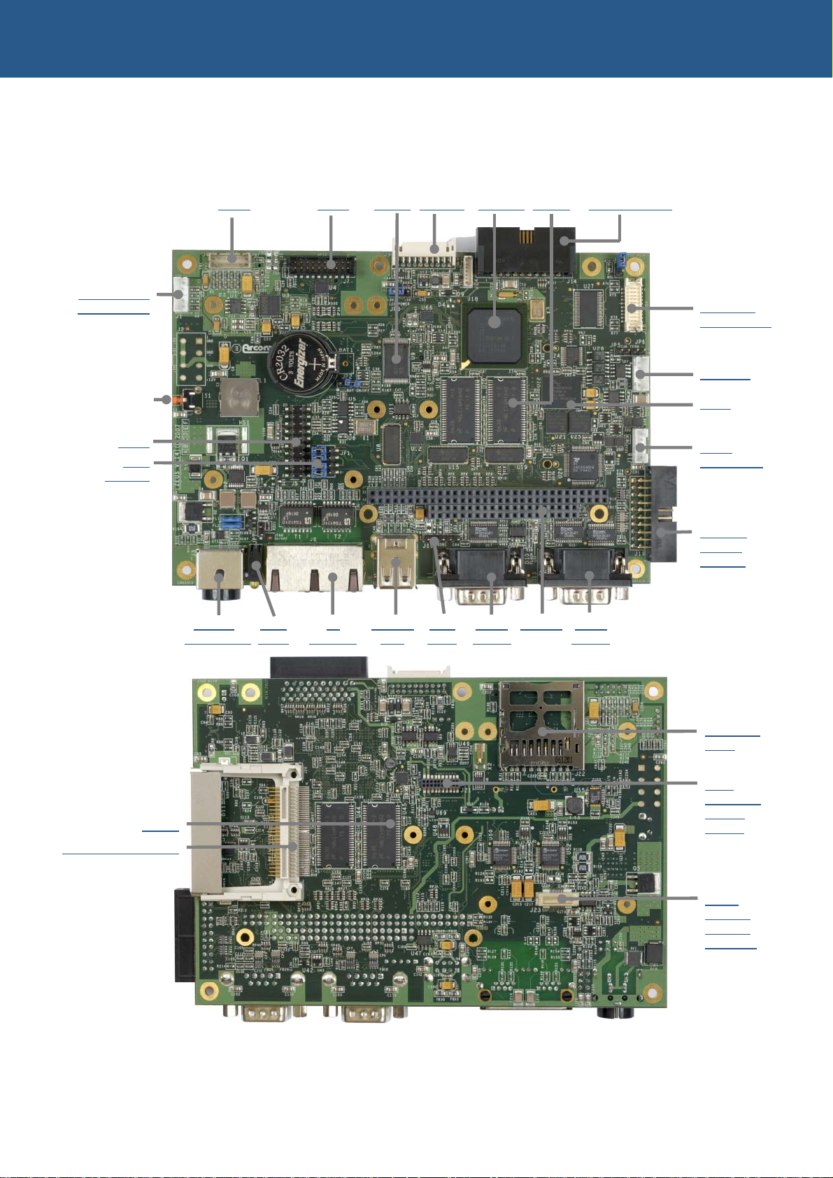
ZEUS ‘at a glance’
10-30V input option
Audio GPIO SRAM Camera PXA270 DRAM Flat panel LCD
Touchscreen
4-wire/5-wire
Reset switch
JTAG
Use
jumpers
10-30V User 2x 2x USB USB Serial PC/104 Serial
Power input
LEDs Ethernet host client RS232 RS232
Flat panel
LCD – LVDS
CAN bus
Flash
Serial
RS422/485
2x serial
RS232/
485/422
SD/SDIO/
MMC
IEEE
802.15.4 /
DRAM
CompactFlash (CF+)
ZigBee
header
ZEUS
wireless
modem/
GPS port
© 2007 Eurotech Ltd Issue D 8
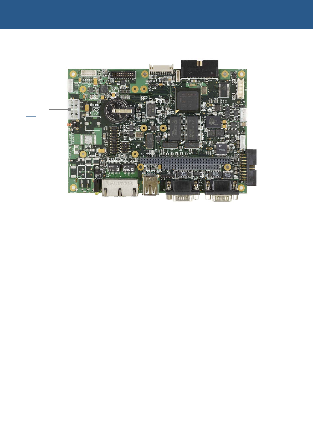
ZEUS Technical Manual Introduction
5V input option
5V power
input
© 2007 Eurotech Ltd Issue D 9

ZEUS Technical Manual Introduction
ZEUS features
Microprocessor
• PXA270 312/416/520MHz processor (520MHz fitted as standard).
Cache
• 32K data cache, 32K instruction cache, 2K mini data cache.
System memory
• Fixed on-board memory:
- 64/128/256 MB SDRAM (32-bit wide SDRAM data bus).
Flash memory
• Fixed on-board memory - 32/64MB Flash.
SRAM
• 256 KB of SRAM battery backed on board.
Video
• 18-bit flat panel interface for STN and TFT displays.
• Optional LVDS interface.
Serial ports
• 4x UART fast serial ports - 4x 16550 compatible UARTs (921.6Kbaud):
Wireless support
• GSM/GPRS, iDEN, CDMA modem and GPS using low profile add-on module.
• IEEE802.15.4 / ZigBee wireless interface using low profile add-on module.
Network support
• 2x 10/100Base-T Ethernet controllers (Davicom DM9000A).
• On-board dual-port RJ45 jack with LEDs.
- 1x RS422/485 - software selectable.
- 1x RS232/422/485 - software selectable.
- 2x RS232.
• Factory build option for external Power-over-Ethernet (PoE).
USB support
• 2x USB 1.1 host controller ports supporting 12MB/s and 1.5MB/s speeds.
• Alternatively, one host channel may be configured as a USB 1.1 client controller
port supporting 12MB/s and 1.5MB/s speeds.
• Power switch included on board with 500mA current limit.
• 2x USB A-type connectors for host ports.
• Header for client port.
© 2007 Eurotech Ltd Issue D 10

ZEUS Technical Manual Introduction
Expansion interfaces
• CompactFlash CF+ socket to support Type I,II form factor CF+ cards.
• SDIO socket to support MMC/SD/SDIO cards.
• 16-bit PC/104 interface.
Date/time support
• Real time clock – battery backed on-board (external to PXA270).
Audio and touchscreen
• Wolfson WM9712L AC’97 compatible CODEC.!
• Line in, line out, microphone in, stereo amp out.
• Touchscreen support – 4/5-wire analogue resistive.
Quick Capture camera interface
• Intel Quick Capture technology.
• Header connector to a camera image sensor.
2
C bus
I
• Multi-master serial bus, header connection.
Configuration EPROM
2
C EPROM for storing configuration data.
• I
CAN bus
• Optional CAN 2.0B protocol controller and optoisolated transceiver.
Watchdog timer
• External to PXA270, generates reset on timeout. Timeout range 1ms-60s.
General I/O
• 16 x general purpose I/O (20-pin header).
Temperature sensor
2
C temperature sensor.
• I
User LEDs
• Front panel user LEDs (3x yellow).
Test support
• JTAG interface (standard 20-pin ARM header).
Reset
• Reset button.
Power requirements
• 5V operation (8-pin ATX style connector) or 10-30V input (front panel DC
connector).
© 2007 Eurotech Ltd Issue D 11

ZEUS Technical Manual Introduction
Mechanical
• EPIC form factor (115mm x 165mm).
Environmental
• Operating temperature:
- Commercial: -20°C (-4°F) to +70°C (+158°F) for speed variants up to 520MHz.
- Industrial: -40°C (-40°F) to +85°C (+185°F) for speed variants up to 416MHz.
• RoHS Directive Compliant (2002/95/EC).
© 2007 Eurotech Ltd Issue D 12

ZEUS Technical Manual Introduction
ZEUS support products
The following products support the ZEUS:
• ZEUS Modem Board 1, a low profile module attached to the solder side of the
ZEUS main board. It provides the following wireless connectivity options:
- Quad band GSM/GPRS: Sony Ericsson GR64 or Dual band Siemens MC39i
module.
- iDEN: Motorola iO270 module (includes internal GPS receiver).
- GPS: Fastrax iTRAX0312 channel GPS receiver module.
See ZEUS Modem Board 1
• ZEUS Modem Board 2, a low profile module attached to the solder side of the
ZEUS board. It provides the following wireless connectivity:
- Quad band GSM/GPRS: TELIT GE863-GPS module (includes internal GPS
receiver).
See ZEUS Modem Board 2
• ZEUS Modem Board 3, a low profile module attached to the solder side of the
ZEUS main board. It provides the following wireless connectivity:
- GSM/GPRS: SierraWireless MC8780/MC8775/MC8755 modules.
- CDMA: SierraWireless MC5720/MC5725 modules.
- GPS: Fastrax iTRAX0312 channel GPS receiver module.
See ZEUS Modem Board 3
• ZigBee module (ZMx), a direct plug-in option for the ZEUS board that provides
ZigBee (see www.zigbee.org
It provides a fully functioning IEEE802.15.4 / ZigBee controller.
See IEEE802.15.4 / ZigBee module (ZMx)
, page 118 , for further details.
, page 118 , for further details.
, page 119 , for further details.
) and IEEE 802.15.4 compatible wireless connectivity.
, page 37, for further details.
• ZEUS-FPIF (Flat Panel Interface), a simple board that enables easy connection
between the ZEUS and a variety of LCD flat panel displays.
See ZEUS-FPIF
• ZEUS-FPIF-CRT, a board that allows the ZEUS to drive a CRT Monitor or an
analogue LCD flat panel. Sync on green and composite sync monitors are not
supported.
See ZEUS-FPIF-CRT
Contact Eurotech Sales
products.
© 2007 Eurotech Ltd Issue D 13
, page 122, for further details.
, page 127, for further details.
, page 97, for further information about any of the above
ZEUS Technical Manual About this manual
About this manual
This manual describes the operation and use of the ZEUS single board computer. It is
designed to be a reference and user manual and includes information about all aspects
of the board.
Conventions
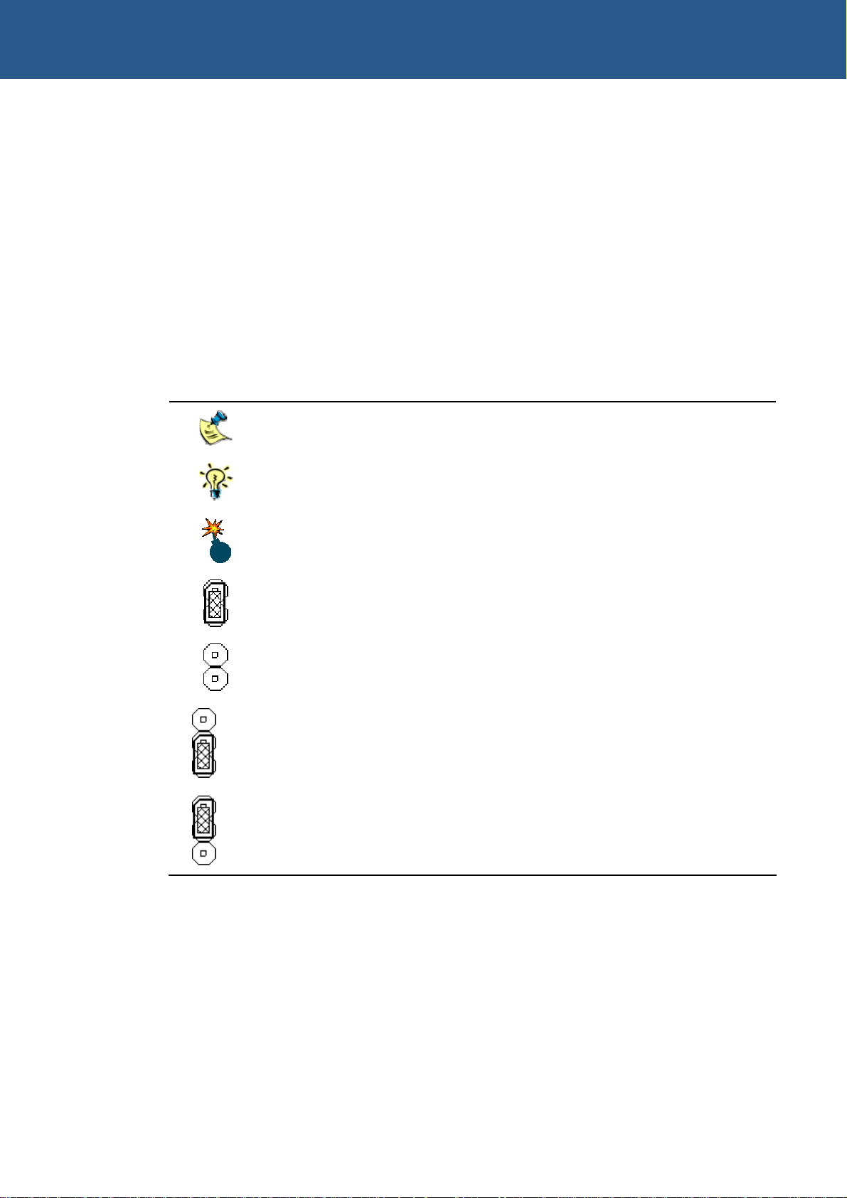
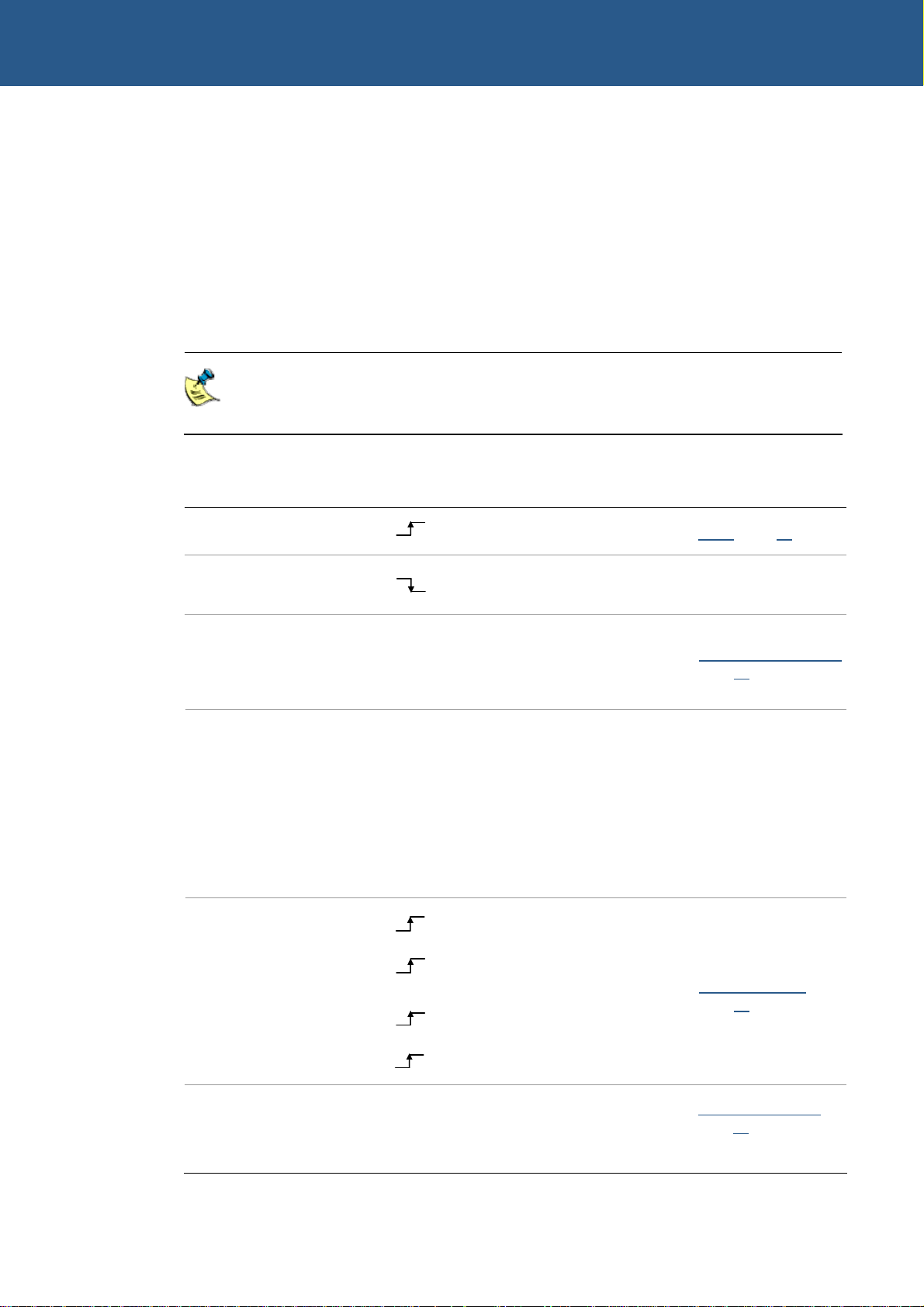
Symbols
The following symbols are used in this guide:
Symbol Explanation
Note - information that requires your attention.
Tip - a handy hint that may provide a useful alternative or save time.
Caution – proceeding with a course of action may damage your
equipment or result in loss of data.
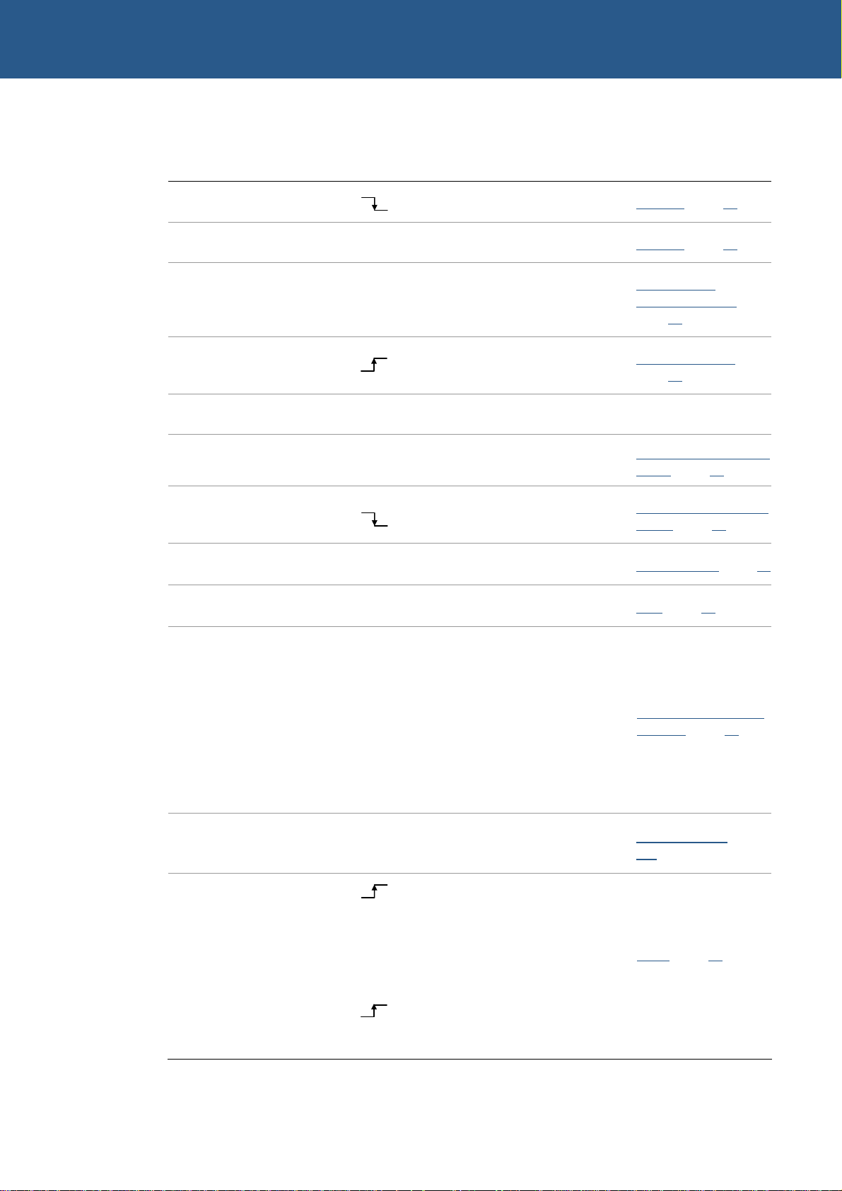
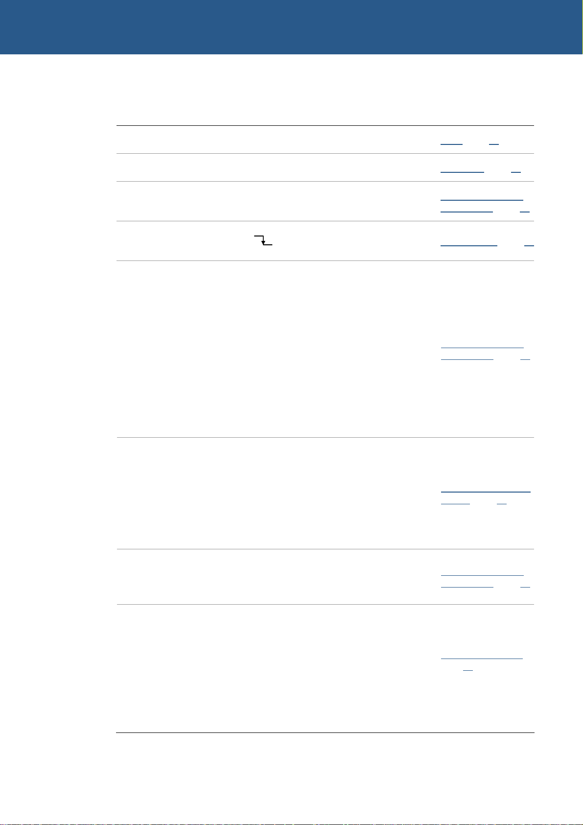
Jumper is fitted.
Jumper is not fitted.
3
2
1
3
2
1
Jumper fitted on pins 1-2.
Jumper fitted on pins 2-3.
© 2007 Eurotech Ltd Issue D 14

ZEUS Technical Manual About this manual
Tables
With tables such as that shown below, the white cells show information relevant to the
subject being discussed. Grey cells are not relevant in the current context.
Byte lane Most significant byte Least significant byte
Bit 15 14 13 12 11 10 9 8 7 6 5 4 3 2 1 0
AUTO_
Field - - - - - - - - - - - - -
RETRIG
Reset X X X X X X X X 0 0 0 0 0 0 0 0
R_DIS
CLR
Relevant
information
© 2007 Eurotech Ltd Issue D 15

ZEUS Technical Manual Getting started
Getting started
A ZEUS Quickstart Manual is provided with each Development Kit to enable you to set
up and start using the ZEUS board. Please read the relevant manual and follow the
steps explaining how to set up the board. Once you have completed this task, and your
ZEUS system is working, you can start adding further peripherals enabling
development to begin.
This section explains how to set up and use some of the features of the ZEUS. For
more detailed information on any aspect of the board see the section Detailed
hardware description
Using the ZEUS
Using the CompactFlash socket
The ZEUS is fitted with a Type I/II CompactFlash socket mounted on the solder side of
the board. The socket is connected to Slot 0 of the PXA270 PC card interface. It
supports 3.3V Type I and II CompactFlash cards, for both memory and I/O. The ZEUS
supports hot swap changeover of the cards and notification of card insertion.
, page 18.
For more details see Expansion interfaces
5V CompactFlash cards are not supported.
Using the serial interfaces (RS232/422/485)
The four standard serial port interfaces on the ZEUS are fully 16550 compatible.
Connection to the serial ports is made via two DB9 connectors, a 20-way header and a
simple 5 way header. The pin assignment of the 20 way header has been arranged to
enable 9-way IDC D-Sub plugs to be connected directly to the cable. See the section
J19 – Serial ports – COM3/4
See the section Serial COM ports
Using the audio features
There are four audio interfaces supported on the ZEUS: amp out, line out, line in and
microphone. The line in, line out and amp interfaces support stereo signals and the
microphone provides a mono input. The amplified output is suitable for driving an 8Ω
load with a maximum power output of 250mW per channel.
Connections are routed to J11. See the sections Audio
connector
, page 79, for further details.
, page 38.
, page 88, for pin assignments and connector details.
, page 53, for further details.
, page 49, and J4 – Audio
Using the USB ports
The standard dual USB type ‘A’ connector is provided on the front panel. See the
sections USB
© 2007 Eurotech Ltd Issue D 16
, page 51, and J8 – USB connector, page 81, for further details.

ZEUS Technical Manual Getting started
Using the Ethernet interface
The boot loader configures the Davicom DM9000A 10/100BaseTX Ethernet controller.
Connection is made via a dual RJ45 connector. See the sections Ethernet
and J6 – Ethernet connector
, page 80, for further details.
, page 52,
Using the PC/104 expansion bus
PC/104 modules can be used with the ZEUS to add extra functionality to the system.
This interface supports 8/16 bit ISA bus style peripherals.
Eurotech Ltd has a wide range of PC/104 modules, which are compatible with the ZEUS.
These include modules for digital I/O, analogue I/O and motion control. Please contact
Eurotech Sales
be available as these modules are in continuous development.
In order to use a PC/104 board with the ZEUS it should be plugged into J12 for 8-bit
cards and J12/J13 for 8/16-bit cards. See the sections ZEUS PC/104 interface details
page 41
, and J12 & J13 – PC/104 connectors, page 84, for further details.
(see page 97) if a particular interface you require does not appear to
,
The ISA interface on the ZEUS does not support DMA, shared interrupts and some
access modes. See the section PC/104 interrupts
interrupt use.
The ZEUS provides +5V to a PC/104 add-on board via the J12 and J13 connectors. If
a PC/104 add-on board requires a +12V supply, then +12V must be supplied to the
ZEUS power connector J2 pin 4. If –12V or –5V are required, these must be supplied
directly to the PC/104 add-on board.
Using the ZEUS Modem Modules
The ZEUS Modem modules can be used with the ZEUS to add wireless and GPS
functionality to the system. Various wireless modems are supported to provide packet
data, circuit switched data and voice connectivity on a wireless network. A 12 channel
GPS receiver is also available on the ZEUS Modem module. The ZEUS Modem
module is fitted on the solder side of the ZEUS board (connector J23).
The FFUART serial port of PXA270 is used to communicate with the wireless modem,
and STUART is used to communicate with GPS module. See the sections Wireless
modem and GPS receiver
interface
, page 91, for further details.
Using the ZigBee Module
The ZEUS ZigBee module can be used with the ZEUS to provide ZigBee
(www.zigbee.org
serial port of PXA270 is used to communicate with the ZigBee module. The ZigBee
module is fitted on the solder side of the ZEUS board (connector J21). For further
details, see sections IEEE802.15.4 / ZigBee module
) and IEEE 802.15.4 compatible wireless connectivity. The BTUART
, page 42, for details about PC/104
, page 35, and J23 – Wireless modem/GPS module
, page 37.
© 2007 Eurotech Ltd Issue D 17
ZEUS Technical Manual Detailed hardware description
Detailed hardware description
This section provides a detailed description of the functions provided by the ZEUS.
This information may be required during development after you have started adding
extra peripherals, or are starting to use some of the embedded features.
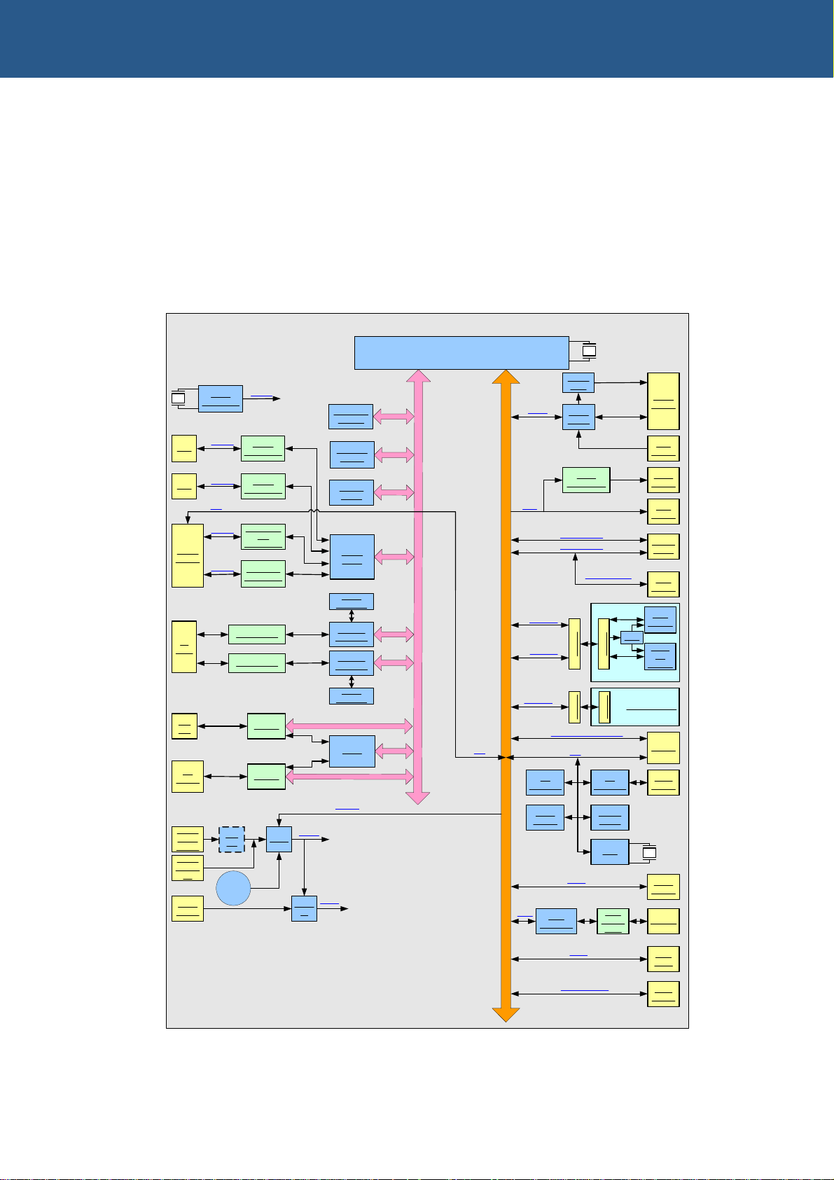
ZEUS block diagram
The following diagram illustrates the functional organization of the ZEUS EPIC single
board computer:
ZEUS
PXA270
Power
Codec
Transmitter
USB 1.1 Host
USB 1.1 Host
STUART
FFUART
Quick Capture Camera
I/O
Expander
Temp
Sensor
JTAG
CAN
controller
Amp
AC'97
LVDS
USB 1.1 Client
Header
Header
I2C
GPIO
Socket
Socket
I/O
Expander
Config
PROM
RTC
CAN
Transc
eiver
Audio
Header
TSC
Header
LVDS
Header
LCD
Header
2xUSB
Conn.
USB
Header
GPS
Module
PSU
GSM/
3G
Module
Daughter Board
ZigBee Module
Header
GPIO
Header
JTAG
Header
Header
User
LEDs
DB9
DB9
COMS
Header
2x
RJ45
PC/
104
CF
Socket
Power
Conn.
10-30V
Power
Header
5V
Reset
Button
Clock
Generation
COM 1
COM 2
I2C
COM 3
COM 4
DC/
DC
Battery
Clocks
RS232
Transceiver
RS232
Transceiver
RS232/422/
485
Transceiver
RS422/485
Transceiver
Transformer
Transformer
Buffers
Buffers
5V
PSUs
Power
Reset
IC
Reset
64/128 MB
SDRAM
32/64 MB
FLASH
256 KB
SRAM
QUAD
UART
Serial
EEPROM
Ethernet
Controller
Ethernet
Controller
Serial
EEPROM
CPLD
PM I2C
AC’97
LCD
S
U
B
R
E
L
L
O
R
T
N
O
C
Y
R
O
M
E
M
BTUART
PERIPHERALS / GPIO
I2C
SPI1
MMC/SD/SDIO
SDIO
Socket
© 2007 Eurotech Ltd Issue D 18

ZEUS Technical Manual Detailed hardware description
ZEUS address map
PXA270 chip select Physical address Bus width Description
CS0# 0x00000000 – 0x03FFFFFE 16-bit Flash memory/Silicon disk
CS1# 0x04000000 – 0x07FFFFFE 16-bit Ethernet controller 0
CS2# 0x08000000 – 0x0BFFFFFE 16-bit Ethernet controller 1
CS3# 0x0C000000 – 0x0FFFFFFF - Reserved
CS4# 0x10000000 – 0x11FFFFFE 16-bit Quad UART
0x12000000 – 0x13FFFFFE 16-bit CPLD registers
CS5# 0x14000000 – 0x17FFFFFE 16-bit SRAM
- 0x18000000 – 0x1FFFFFFF - Reserved
- 0x20000000 – 0x2FFFFFFE 16-bit CompactFlash
- 0x30000000 – 0x300003FF 8/16-bit PC/104 I/O space
- 0x30000400 – 0x3BFFFFFF - Reserved
- 0x3C000000 – 0x3C1FFFFF 8/16-bit PC/104 memory space
- 0x3C200000 – 0x3FFFFFFF - Reserved
- 0x40000000 – 0x43FFFFFF 32-bit PXA270 peripherals
- 0x44000000 – 0x47FFFFFC 32-bit LCD control registers
- 0x48000000 – 0x4BFFFFFC 32-bit Memory controller registers
- 0x4C000000 – 0x4FFFFFFC 32-bit USB host registers
- 0x50000000 – 0x53FFFFFC 32-bit Capture interface registers
- 0x54000000 – 0x57FFFFFC 32-bit Reserved
- 0x58000000 – 0x5BFFFFFC 32-bit Internal memory control
- 0x5C000000 – 0x5C00FFFC 32-bit Internal SRAM bank 0
- 0x5C010000 – 0x5C01FFFC 32-bit Internal SRAM bank 1
- 0x5C020000 – 0x5C02FFFC 32-bit Internal SRAM bank 2
- 0x5C030000 – 0x5C03FFFC 32-bit Internal SRAM bank 3
- 0x5C040000 – 0X7FFFFFFF - Reserved
SDCS0# 0x80000000 – 0x8FFFFFFF 32-bit SDRAM (U2/U3)
SDCS1# 0x90000000 – 0x9FFFFFFF 32-bit SDRAM (U41/U49)
1
1
1
1
1
1
UART and CPLD address map
PXA270 chip select Physical address Bus width Description
CS4#
1
Details of the internal registers are in the Intel PXA27x Processor Family Developer’s
Manual on the Development Kit CD.
© 2007 Eurotech Ltd Issue D 19
0x10000000 – 0x107FFFFE 16-bit UART 1
0x10800000 – 0x10FFFFFE 16-bit UART 2
0x11000000 – 0x117FFFFE 16-bit UART 3
0x11800000 – 0x11FFFFFE 16-bit UART 4
0x12000000 16-bit REG0 (CPLD Ver/Issue)
0x12800000 16-bit REG1 (PC104 IRQ status)
0x13000000 16-bit REG2 (CF Reset)
0x13800000 16-bit REG3 (WD Register)

ZEUS Technical Manual Detailed hardware description
PXA270 processor
The ZEUS board is based on a PXA270 processor. The PXA270 processor is an
integrated system-on-a-chip microprocessor for high performance, low power portable
handheld and handset devices. It incorporates the Intel XScale technology with on-thefly voltage and frequency scaling and sophisticated power management.
The PXA270 processor complies with the ARM Architecture V5TE instruction set
(excluding floating point instructions) and follows the ARM programmer’s model. The
PXA270 processor also supports Intel Wireless MMX integer instructions in
applications such as those that accelerate audio and video processing.
The features of the PXA270 processor include:
• Intel XScale core.
• Power management.
• Internal memory - 256KB of on-chip RAM.
• Interrupt controller.
• Operating-system timers.
• Pulse-width modulation unit (PWM).
• Real time clock (RTC).
• General-purpose I/O (GPIO).
• Memory controller.
• DMA controller.
• Serial ports:
- 3x UART.
- Fast infrared port.
- I2C bus port.
- AC97 Codec interface.
- I2S Codec Interface.
- USB host controller (2 ports).
- USB client controller.
- 3x synchronous serial ports (SSP).
• LCD panel controller.
• Multimedia card, SD memory card and SDIO card controller.
• Memory stick host controller.
• Mobile scalable link (MSL) interface.
• Keypad interface.
• Universal subscriber identity module (USIM) interface.
• Quick Capture camera interface.
• JTAG interface.
• 356-pin VF-BGA packaging.
© 2007 Eurotech Ltd Issue D 20

ZEUS Technical Manual Detailed hardware description
The design supports 520MHz, 416MHz and 312MHz speed variants of the PXA270
processor. The standard variant of the ZEUS board is fitted with the 520MHz version of
PXA270. The maximum speed available for extended temperature versions of the
ZEUS is 416MHz.
A 13MHz external crystal is used to run the PXA270 processor. All other clocks are
generated internally in the processor.
The PXA270 processor family provides multimedia performance, low power
capabilities and rich peripheral integration. Designed for wireless clients, it incorporates
the latest Intel advances in mobile technology over its predecessor, the PXA255
processor. The PXA270 processor features scalability by operating from 104MHz up to
520MHz, providing enough performance for the most demanding control and
monitoring applications.
PXA270 is the first Intel Personal Internet Client Architecture (PCA) processor to
include Intel Wireless MMX technology, enabling high performance, low power
multimedia acceleration with a general-purpose instruction set. Intel Quick Capture
technology provides a flexible and powerful camera interface for capturing digital
images and video. Power consumption is also a critical component. Wireless Intel
SpeedStep technology provides the new capabilities in low power operation.
The processor requires a number of power supply rails. All voltage levels are
generated on-board from either the DC/DC PSU or from the single +5V power input.
The ZEUS uses a specialized Power Management IC to support Intel SpeedStep
technology.
The PXA270 processor is a low power device and does not require a heat sink for
operating temperatures up to 85°C (185°F).
© 2007 Eurotech Ltd Issue D 21
ZEUS Technical Manual Detailed hardware description
PXA270 GPIO pin assignments
The table below summarizes the use of the 118 PXA270 GPIO pins, their direction,
alternate function and active level.
Key:
AF Alternate function.
Dir Pin direction.
Active Function active level or edge.
For details of pin states during sleep modes and reset see the Pin Usage table
in the Intel PXA27x Processor Family Electrical, Mechanical and Thermal
Specification.
GPIO
No AF Signal name Dir Active
0 0 AC97_IRQ
1 0 DS_WAKEUP
3 0 PWR_SCL
4 0 PWR_SDA
5 N/A PWR_CAP0
6 N/A PWR_CAP1
7 N/A PWR_CAP2
8 N/A PWR_CAP3
9 0 UART_INTA
Input
Input
Output
Bidir.
Power
Power
Power
Power
Input
Wake-up
Function
AC97Interrupt
Reset in case of power
failure
PXA270 Power Manager I2C
Dedicated function - To
achieve low power during
sleep
UART 1 Interrupt
source See section…
3
3
Audio, page 49
Power management IC
page 64
N/A
3
,
10 0 UART_INTB
11 0 UART_INTD
12 0 UART_INTC
13 0 USER_LINK1
© 2007 Eurotech Ltd Issue D 22
Input
Input
Input
Input
UART 2 Interrupt
UART 4 Interrupt
UART 3 Interrupt
User Configurable Input
3
3
3
3
Serial COM ports
page 53
JP1 – User jumpers
page 93
,
continued…
,
ZEUS Technical Manual Detailed hardware description
GPIO
No AF
14 0 ETH0_IRQ# Input
15 2 ETH_CS1# Output Low Chip Select 1 – Ethernet 0 Ethernet, page 52
16 2 PWM0 Output
17 0 ISA_IRQ Input
18 0 RESERVED
19 0 BKLEN Output High LCD Backlight Enable
20 0 ISA_RST# Input
Signal name Dir Active
Inverter
Function
Ethernet 0 Interrupt
See
Backlight Brightness On/Off
data
or variable if PWM
sheet
‘OR’ of PC/104 interrupts
PC104 Reset Indication (IRQ)
Wake-up
source See section…
3
3
Ethernet, page 52
LCD backlight
brightness control
page 47
PC/104 interrupts,
page 42
LCD logic and backlight
power, page 46
ZEUS PC/104 interface
details, page 41
,
21 0 LVDS_EN Output High LVDS Transceiver Enable LVDS interface, page 47
22 0 USB_PWE2 Output High USB Port 2 Power Enable USB, page 51
23 1 CIF_MCLK Output
24 1 CIF_FV Input NA
25 1 CIF_LV Input NA
26 2 CIF_PCLK Input
27 0 PTT Input
28 1
29 1 AC97_DIN Input NA AC97 DATA IN
30 2 AC97_DOUT Output NA AC97 DATA OUT
AC97_BITCLK
Input
Camera Interface Master
NA
Clock
Camera Interface Frame
Sync -Vertical
Camera Interface Line Sync
- Horizontal
Camera Interface Pixel
NA
Clock
Hi g h Pu s h To Tal k
AC97 BIT CLOCK
Quick Capture camera
interface
ZEUS Modem-1, page
118
Audio, page 49
, page 59
31 2 AC97_SYNC Output
© 2007 Eurotech Ltd Issue D 23
AC97 SYNC
continued…
ZEUS Technical Manual Detailed hardware description
GPIO
No AF
32 2 MMCLK Output NA SDIO Clock SDIO, page 39
33 2 SRAM_CS5# Output Low Chip Select 5 - SRAM Static RAM, page 34
34 1 GSM_FFRXD Input NA Modem Receive Data
35 0 CF_CD# Input
36 1
37 1
38 1 GSM_FFRI# Input NA Modem Ring Indicator
39 2 GSM_FFTXD Output NA Modem Transmit Data
40 2
Signal name Dir Active
GSM_FFDCD#
GSM_FFDSR#
GSM_FFDTR#
Input NA Modem Data Carrier Detect
Input NA Modem Data Sender Ready
Output NA
Function
Compact Flash Card Detect
IRQ
Modem Data Terminal
Ready
Wake-up
source See section…
Wireless modem and
GPS receiver
3
CompactFlash
Wireless modem and
GPS receiver
, page 35
, page 40
, page 35
41 2
42 1 ZB_BTRXD Input NA ZigBee Receive Data
43 2 ZB_BTTXD Output NA ZigBee Transmit Data
44 1 ZB_BTCTS# Input NA ZigBee Clear To Send
45 2 ZB_BTRTS# Output NA ZigBee Request To Send
46 2
47 1
48 2 CB_POE# Output Low Card Bus Output Enable
49 2 CB_PWE# Output Low Card Bus Write Enable
50 2 CB_PIOR# Output Low Card Bus I/O Read
51 2 CB_PIOW# Output Low Card Bus I/O Write
GSM_FFRTS#
GPS_STDRXD
GPS_STDTXD
Output NA Modem Request To Send
Input
Output
NA GPS Receive Data
NA GPS Transmit Data
IEEE802.15.4 / ZigBee
module, page 37
Wireless modem and
GPS receiver
Expansion interfaces
page 38
, page 35
,
continued…
© 2007 Eurotech Ltd Issue D 24

ZEUS Technical Manual Detailed hardware description
GPIO
No AF
52 0 MMC_WP Input
53 0 MMC_CD Input
54 2 CB_PCE2# Output Low Card Bus High Byte Enable
55 2
56 1 CB_WAIT# Input
57 1
58 2 LCD_D0 Output
59 2 LCD_D1 Output
60 2 LCD_D2 Output
61 2 LCD_D3 Output
62 2 LCD_D4 Output
63 2 LCD_D5 Output
Signal name Dir Active
CB_PREG#
CB_PIOIS16#
Output Low
Input
Function
Low SDIO Write Protect Status
SDIO Card Detect IRQ
Card Bus Register Space
Select
Low Card Bus WAIT#
Low Card Bus IOIS16#
NA LCD Data Bit 0
NA LCD Data Bit 1
NA LCD Data Bit 2
NA LCD Data Bit 3
NA LCD Data Bit 4
NA LCD Data Bit 5
Wake-up
source See section…
SDIO
, page 39
3
Expansion interfaces
page 38
,
64 2 LCD_D6 Output
65 2 LCD_D7 Output
66 2 LCD_D8 Output
67 2 LCD_D9 Output
68 2 LCD_D10 Output
69 2 LCD_D11 Output
70 2 LCD_D12 Output
71 2 LCD_D13 Output
72 2 LCD_D14 Output
73 2 LCD_D15 Output
74 2 LCD_FCLK Output
75 2 LCD_LCLK Output
76 2 LCD_PCLK Output
NA LCD Data Bit 6
NA LCD Data Bit 7
NA LCD Data Bit 8
NA LCD Data Bit 9
NA LCD Data Bit 10
NA LCD Data Bit 11
NA LCD Data Bit 12
NA LCD Data Bit 13
NA LCD Data Bit 14
NA LCD Data Bit 15
LCD Frame Clock (STN) /
NA
Vertical Sync (TFT)
LCD Line Clock (STN) /
NA
Horizontal Sync (TFT)
LCD Pixel Clock (STN) /
NA
Clock (TFT)
Flat panel display
page 44
,
LCD Bias (STN) / Data
77 2 LCD_BIAS Output
© 2007 Eurotech Ltd Issue D 25
NA
Enable (TFT)
continued…
ZEUS Technical Manual Detailed hardware description
GPIO
No AF
78 2 ETH_CS2# Output NA Chip Select 2 - Ethernet 1 Ethernet, page 52
79 1 CB_PSKTSEL Output NA Card Bus Socket Select
80 2 CPLD_CS4# Output Low Chip Select 4 – UART/CPLD
81 1 SPI_TXD3 Output
82 1 SPI_RXD3 Input NA SPI Receive Data
83 1 SPI_CS3# Output Low SPI Chip Select
84 1 SPI_CLK3 Output
85 1 CB_PCE1# Output Low Card Bus Low Byte Enable
86 2 LCD_D16 Output NA LCD Data Bit 16
87 2 LCD_D17 Output NA LCD Data Bit 17
Signal name Dir Active
Function
NA SPI Transmit Data
NA SPI Clock
Wake-up
source See section…
Expansion interfaces,
page 38
UART and CPLD
address map
CAN bus
Expansion interfaces
page 38
Flat panel display
page 44
, page 19
, page 57
,
,
88 0 USB_OC1# Input
89 0 USB_PWE1 Output
90 3 CIF_DD4 Input
91 0 EX_GPIO_IRQ# Input
92 1 MMDAT0 Bidir.
93 2 CIF_DD6 Input
94 2 CIF_DD5 Input
95 1 AC97_RST# Output
96 0 OVERTEMP Input
USB Port 1 Over Current
Detection
High USB Port 1 Power Enable
NA Camera Interface Data 4
External GPIO Interrupt
NA SDIO Data 0
NA Camera Interface Data 6
NA Camera Interface Data 5
Low AC97 Reset Audio
Temperature Sensor
Overtemp IRQ
USB, page 51
Quick Capture camera
interface
3
External General
purpose I/O, page 60
Expansion interfaces
page 38
Quick Capture camera
interface
Temperature sensor
page 61
, page 59
,
, page 59
, page 49
,
continued…
© 2007 Eurotech Ltd Issue D 26
ZEUS Technical Manual Detailed hardware description
GPIO
No AF
97 0 CF_PWEN Output High
98 2 CIF_DD0 Input NA Camera Interface Data 0
99 0 CF_RDY Input NA
100 3 GSM_FFCTS# Input NA Modem Clear To Send
101 0 LCD_EN Output High LCD Logic Supply Enable
102 0 USER_LINK2 Input NA User Configurable
103 1 CIF_DD3 Input
Signal name Dir Active
Function
Compact Flash Power
Enable
Compact Flash Ready/Busy
Status Flag
NA Camera Interface Data 3
Wake-up
source See section…
CompactFlash, page 40
Quick Capture camera
interface
CompactFlash
Wireless modem and
GPS receiver
Flat panel display
page 44
JP1 – User jumpers
3
page 93
, page 59
, page 40
, page 35
,
,
104 1 CIF_DD2 Input
105 1 CIF_DD1 Input
106 1 CIF_DD9 Input
107 1 CIF_DD8 Input
108 1 CIF_DD7 Input
109 1 MMDAT1 Bidir.
110 1 MMDAT2 Bidir.
111 1 MMDAT3 Bidir.
112 1 MMCMD Bidir.
113 0 ETH1_IRQ# Input
114 0 USB_OC2# Input
115 0 IG_FAIL Input
NA Camera Interface Data 2
NA Camera Interface Data 1
NA Camera Interface Data 9
NA Camera Interface Data 8
NA Camera Interface Data 7
NA SDIO Data 1
NA SDIO Data 2
NA SDIO Data 3
NA SDIO Command
Ethernet 1 Interrupt
USB Port 2 Overcurrent
Detection IRQ
Ignition Fail IRQ
3
USB
Quick Capture camera
interface
Expansion interfaces
page 38
Ethernet
Power supplies
63
, page 59
, page 52
, page 51
, page
,
116 0 CAN_IRQ# Input
117 1 I2C _SCL Output
118 1 I2C _SDA Bidir.
© 2007 Eurotech Ltd Issue D 27
CAN Bus Interrupt
NA I2C Clock
NA I2C Data
3
CAN bus
I²C bus, page 58
, page 57

ZEUS Technical Manual Detailed hardware description
Interrupt assignments
Internal interrupts
For details on the PXA270 interrupt controller and internal peripheral interrupts please
see the Intel PXA27x Processor Family Developer’s Manual on the Development Kit
CD.
External interrupts
The following table lists the PXA270 signal pins used for external interrupts:
PXA270 Pin Signal name Peripheral Wake-up Active
GPIO0 AC97_IRQ
GPIO1 GPIO_IRQ#
GPIO9 UART_INTA
GPIO10 UART_INTB
GPIO11 UART_INTD
GPIO12 UART_INTC
GPIO13 USER_LINK1
GPIO14 ETH0_IRQ#
GPIO17 ISA_IRQ
GPIO20 ISA_RST#
GPIO35 CF_CD#
GPIO53 MMC_CD
GPIO88 USB_OC1#
Audio
External GPIO
UART 1
UART 2
UART 4
UART 3
User defined
Ethernet 0
PC/104
PC/104
CompactFlash
SDIO
USB1
3
3
3
3
3
3
3 User defined
3
3
3
3
GPIO91 USER_LINK2
GPIO96 OVERTEMP Temperature sensor
GPIO99 CF_RDY CompactFlash Ready = Busy =
GPIO102 USER_LINK2
GPIO113 ETH1_IRQ#
GPIO114 USB_OC2#
GPIO115 IG_FAIL#
GPIO116 CAN_IRQ#
© 2007 Eurotech Ltd Issue D 28
User defined
User defined
Ethernet 1
USB2
PSU (10-30V)
CAN Bus
3 User defined
3 User defined
3
3

3
ZEUS Technical Manual Detailed hardware description
On-Board GPIO expanders pin assignments
Two GPIO expanders (MAX7313) are used to provide additional GPIOs for use with
different on-board peripherals. The GPIO expanders are connected to the I
PXA270 and are accessible through I
2
C bus addresses 0x21 and 0x22.
2
C bus of
The following tables summarize the use of the 17 GPIO pins of MAX7313 on ZEUS
board, and indicate their direction and active level.
Expander 1 - I2C Address 0x21
Power-up
GPIO Signal name Dir Active Function
0 U3_RS232EN Output High UART3 RS232 enable PU
1 U3_RS422EN Output High UART3 RS422 enable PU
2 U3_TERM# Output Low
3 USER_LED1# Output Low User LED 1 PU
4 USER_LED2#
5 USER_LED3# Output Low User LED 3 PU
6 USER_LINK3 Input NA User jumper 3 Jumper
7 NOT USED PU
8 GSM_ON Output
Output
Low User LED 2 PU
See note
1 below
UART3 termination
enable
Modem enable OD
state
PU
See section…
COM3 –
RS232/RS485/RS422
interface
User LEDs
JP1 – User jumpers
, page 54
, page 96
, page 9
9 GSM_STS Input High Modem ON/OFF status Low
10 GPS_ON Output High GPS module enable PU
11 GPS_PSUON Input NA Not Used PU
12 GPS_BOOT Input NA Not Used OD
13 GPS_PPS Input NA GPS Pulse Per Second -
14 USER_LINK4 Input NA User jumper 4 Jumper
15 U4_RS485EN Output High UART4 RS485 enable PU
16 U4_TERM# Output Low
UART4 termination
enable
PU
Wireless modem and GPS
receiver
JP1 – User jumpers
page 93
COM4 – RS422/485
interface
, page 35
,
, page 55
Key:
Dir - Pin direction Active - Function active level or edge
PU - On-board 10K pull-up OD - Open Drain
Note 1: Please see the datasheet of the particular module used.
© 2007 Eurotech Ltd Issue D 29
ZEUS Technical Manual Detailed hardware description
Expander 2 - I2C Address 0x22
GPIO Signal name Dir Active Function
0 CLK_SHDN# Output Low
1 LVDS_FES# Output Low
2 CAN_SHDN Output High
3 U1_RS232_SHDN# Output Low
4 U2_RS232_SHDN# Output Low
5 U3_RS485_SLO# Output Low
6 U4_RS485_SLO# Output Low
Clock Synthesizer
Shutdown
LVDS Falling Edge
Strobe
CAN Transceiver
shutdown
COM1 RS232
transceiver shutdown
COM2 RS232
transceiver shutdown
COM3 RS485
transceiver slew rate
control
COM4 RS485
transceiver slew rate
control
Power-up
state
PU
PU
PU CAN bus
PU
PU
PU
PU
See section…
Clock generator power
management
LVDS interface
page 47
COM Ports power
management
COM3 –
RS232/RS485/RS422
interface
COM4 – RS422/485
interface
, page 72
,
, page 57
, page 73
, page 54
, page 55
7 NOT USED PU
8-11 ISS [0-3] Inputs NA PCB Issue Number
12-15 VER [0-3] Inputs NA PCB Version Number
© 2007 Eurotech Ltd Issue D 30
 Loading...