

Eurotech Appliances CPU-1461 User Manual

EmbeddedDNA
U
-
1
®
PC/104-Plus CPU Module
CP
146
User’s Manual
Rev. 1.0 Jul. 2005
COPYRIGHT 1994-2005 Eurotech S.p.A. All Rights Reserved.

2 PC/104-Plus – CPU-1461 Module
This manual is intended for engineers and programmers. It contains technical specifications, as well as describes
the connectors and how to properly use and configure the product.
Via J. Linussio 1
33020 AMARO (UD)
ITALY
Phone: +39 0433 485 411
Fax: +39 0433 485 499
Web:
http://www.eurotech.it
e-mail: sales@eurotech.it
NOTICE
Although all the information contained herein has been carefully verified, Eurotech S.p.A. assumes no
responsibility for errors that might appear in this document, or for damage to property or persons
resulting from an improper use of this manual and of the related software. Eurotech S.p.A. reserves the
right to change the contents and form of this document, as well as the features and specifications of its
products at any time, without notice.
Trademarks and registered trademarks appearing in this document are the property of their respective owners
PC/104-Plus – CPU-1461 Module 3
Conventions
The following table lists conventions that are used throughout this guide.
Icon Notice Type Description
Information note
Warning
Important features or
instructions
Information to alert you to
potential damage to a program,
system or device or potential
personal injury
Environmental safety
When disposing the equipment, we suggest separating all of its components when possible, and
disposing of them in accordance with local waste disposal legislations.
Be sure to dispose of used batteries as required by local waste disposal legislation. Never throw
batteries into a fire (risk of explosion) or household garbage can.


Contents
Conventions................................................................................................................................................... 3
Environmental safety...................................................................................................................................... 3
Contents........................................................................................................................................................... 5
Chapter 1 Product Overview ...................................................................................................................... 7
Product Definition........................................................................................................................................... 8
Chapter 2 Jumper Description ................................................................................................................... 9
Jumper Layout and Configuration................................................................................................................ 10
Chapter 3 Connectors Description.......................................................................................................... 11
Connectors Layout....................................................................................................................................... 12
How to connect the CPU-1461 to other PC/104 & PC/104-Plus devices: the stack assembly................... 13
J4 for Multifunction and VGA....................................................................................................................... 14
Multifunction Connector Section............................................................................................................ 15
The Eurotech Multifunction Adapter...................................................................................................... 16
VGA Section.......................................................................................................................................... 17
J5 IDE Connector......................................................................................................................................... 18
J7 for USB 2.0 (Ports 5 and 6)..................................................................................................................... 19
J9 Auxiliary Power Connector...................................................................................................................... 20
J14 for USB 1.1 (Ports 7 and 8) and Audio-CODEC................................................................................... 21
The Eurotech USB & AC97-Audio Codec Adapter ............................................................................... 21
J16 for USB 2.0 (Ports 1to 4)....................................................................................................................... 23
J17 for SERIAL1 and SERIAL2 ................................................................................................................... 24
J20 for Ethernet............................................................................................................................................ 25
The Eurotech Ethernet Transceiver...................................................................................................... 26

6 PC/104-Plus – CPU-1461 Module
Chapter 4 The Set-up Program................................................................................................................. 27
The Set-up pages......................................................................................................................................... 30
General Page ........................................................................................................................................ 30
Devices Page........................................................................................................................................ 32
Communications Page.......................................................................................................................... 34
Primary and Secondary ATAPI Page.................................................................................................... 36
Advanced page...................................................................................................................................... 38
PCI Advanced Page.............................................................................................................................. 39
ISA Bus.................................................................................................................................................. 40
Error Handling Page.............................................................................................................................. 40
Chapter 5 Watch Dog Timer ..................................................................................................................... 43
What is a Watch Dog?................................................................................................................................. 44
How to use the Watch Dog.......................................................................................................................... 44
Use the System BIOS INT 52h functions.............................................................................................. 44
Directly accessing Watch Dog I/O mapped registers............................................................................ 45
Chapter 6 Troubleshooting....................................................................................................................... 47
Common Problems and Solutions ............................................................................................................... 48
Troubleshooting a PC/104 System.............................................................................................................. 48
Technical/Sales Assistance......................................................................................................................... 48
Returning For Service..................................................................................................................................49
Appendix ........................................................................................................................................................ 53
A.1 Electrical and Environmental Specifications..................................................................................... 54
Operating Characteristics...................................................................................................................... 54
Absolute Maximum Ratings................................................................................................................... 55
MTBF (Mean Time Between Failures).................................................................................................. 55
A.2 Mechanical Dimensions.................................................................................................................... 56
USB Audio Codec Dimensions.............................................................................................................. 57
Ethernet Adapter Dimensions ............................................................................................................... 57
Multifunction Adapter Dimensions......................................................................................................... 58
A.3 Safety Summary................................................................................................................................58
Ground the Instrument .......................................................................................................................... 59
Do Not Operate in an Explosive Atmosphere ....................................................................................... 59
Keep Away From Live Circuits.............................................................................................................. 59
Use Caution When Exposing or Handling the CRT.............................................................................. 59
Do Not Substitute Parts or Modify Equipment....................................................................................... 59
Observe Dangerous Procedure Warnings............................................................................................ 59
Flammability .......................................................................................................................................... 59
EMI Caution........................................................................................................................................... 59
CE Notice .............................................................................................................................................. 59
Disclaimer of Warranty.......................................................................................................................... 60
Notice .................................................................................................................................................... 60
Reliability............................................................................................................................................... 60
Life Support Policy ................................................................................................................................60
Glossary ......................................................................................................................................................... 61
Acronyms and Abbreviations....................................................................................................................... 67

Chapter 1 Product Overview
The CPU-1461 is a reliable Celeron PC/104-Plus embedded module with 6 fast USB 2.0 ports
For a complete list of related accessories, as well as latest BIOS and drivers, please go to our web site:
www.eurotech.it
In the following paragraphs you will find a description of the CPU-1461characteristics.

8 PC/104-Plus – CPU-1461 Module
Product Definition
Architecture: PC/104-Plus 2.0 compliant
Processor: PentiumIII® 800MHz, 256KB L2 cache, 133MHz PSB
Chipset: Intel® 815E
Memory: 256MB SDRAM soldered on board
Operating Systems: WinCE®, VxWorks®, Linux®, QNX®
BIOS Flash: 1MB Flash EPROM
Interfaces: IDE Controller UltraDMA
2x Serial: 1 RS232, 1 RS232/422/485
2x USB 1.1
6x USB 2.0
Ethernet (10/100 Mbps)
VGA Video Controller
Auxiliary Power
AC97
Keyboard and Mouse
Bus: PC/104-Plus (PCI)
PC/104 (ISA)
Watchdog: 2-255 sec./min.
Power Supply: +5V DC

Chapter 2 Jumper Description
This chapter shows the layout of the jumpers and explains how to set them up.
10 PC/104-Plus – CPU-1461 Module
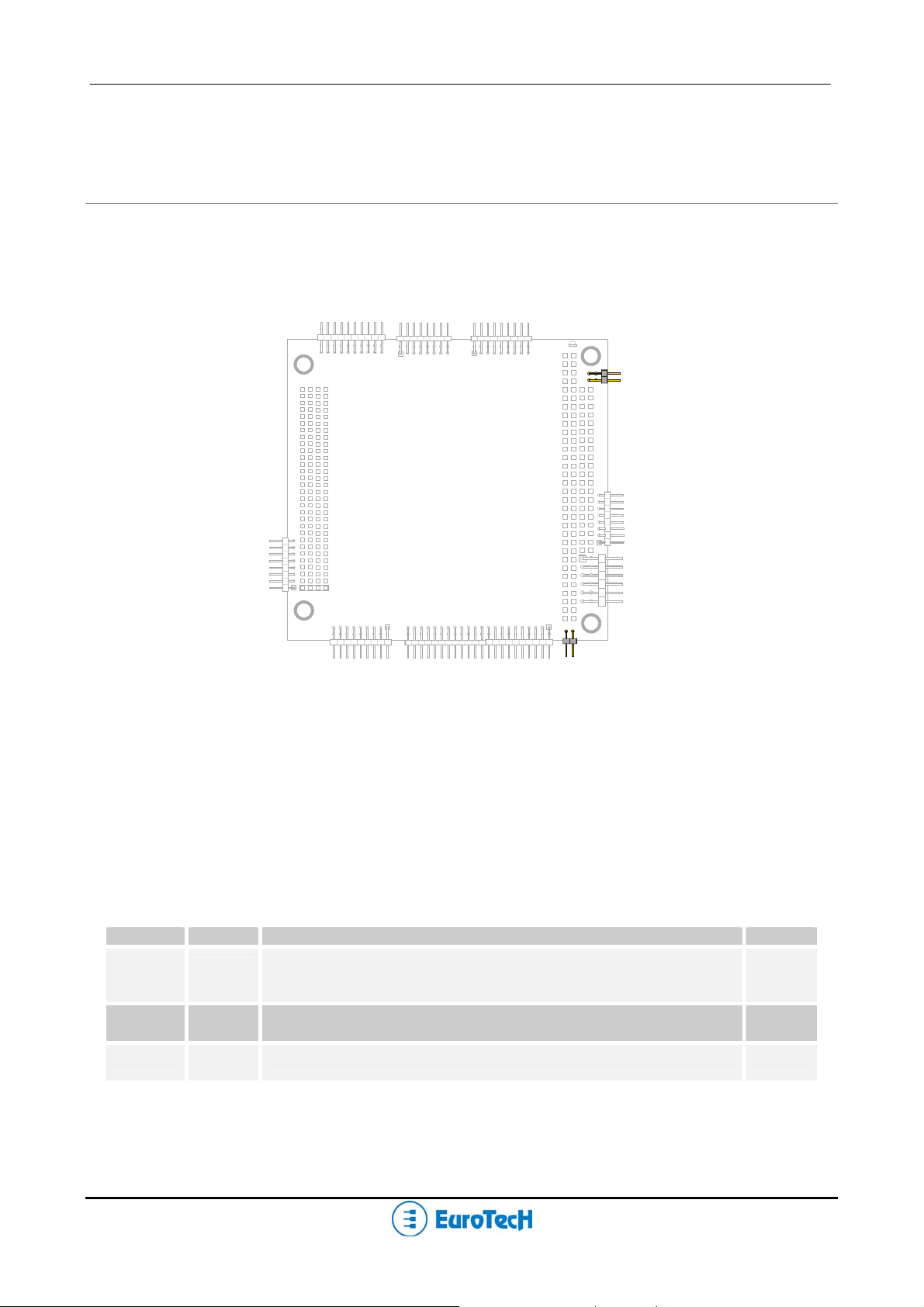
Jumper Layout and Configuration
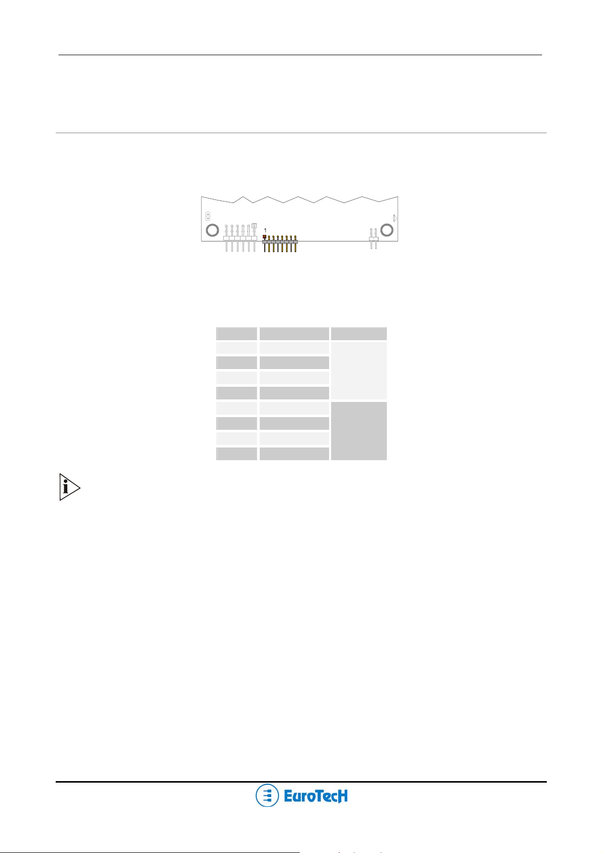
Figure 1 shows the jumper layout of the CPU-1461.
The jumpers are indicated as JP followed by the jumper's number.
JP3
JP2
JP1
Figure 1. Jumpers on the CPU-1461 module
Three 2-pin jumpers (JP1, JP2 & JP3) are located on the module. They can be set as follows:
¾ Pins connected together (which will be indicated as ‘Closed’)
¾ Pins not connected (which will be indicated as ‘Open’)
Table 1 gives a quick cross-reference for them.
Table 1. Jumper Functions
Jumper # Type Function Default
IDE LED
Pin 2 (+): anode LED
Reserved Open
Reserved Open
JP1
JP2
JP3
2 pin
jumper
2 pin
jumper
2 pin
jumper
Pin 1 (-): cathode LED
Open

Chapter 3 Connectors Description
This chapter provides a brief description of the CPU-1461 module’s connecto rs, their positions and functions.
12 PC/104-Plus – CPU-1461 Module
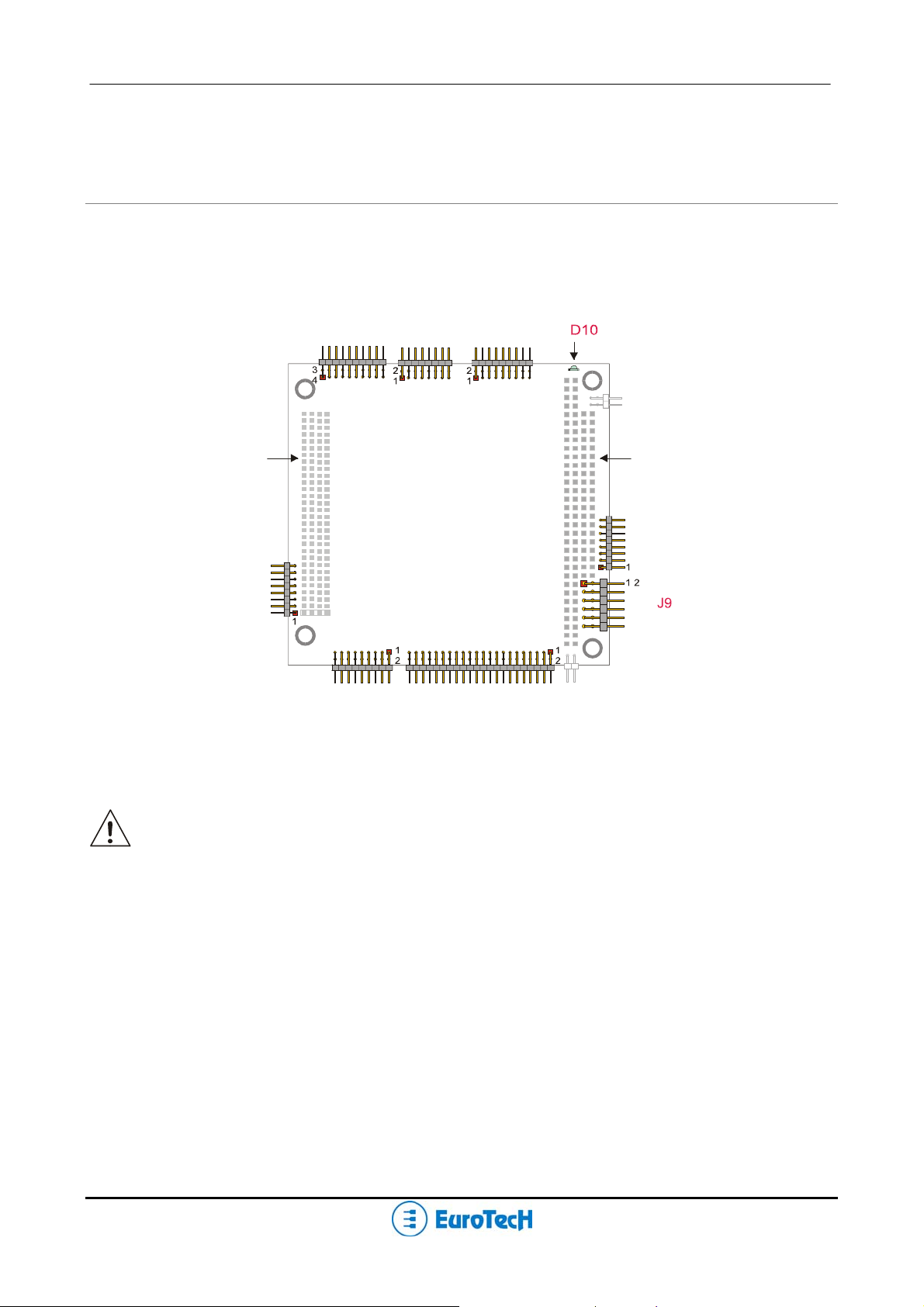
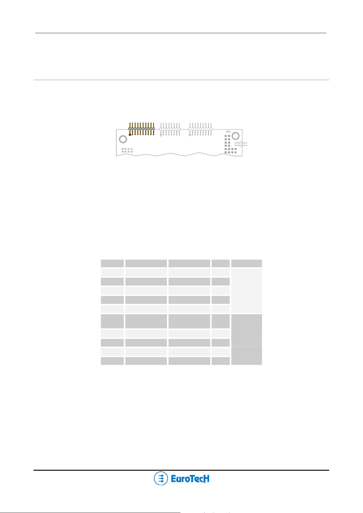
Connectors Layout
Figure 2 shows the connectors with their layout and function(s).
J14 J16 J17
J3
J20
J4
J5
Figure 2. Connector layout
Note: in figure 2, a red square pad indicates pin 1 of each connector.
J1 J2
J7
PC/104-Plus – CPU-1461 Module 13
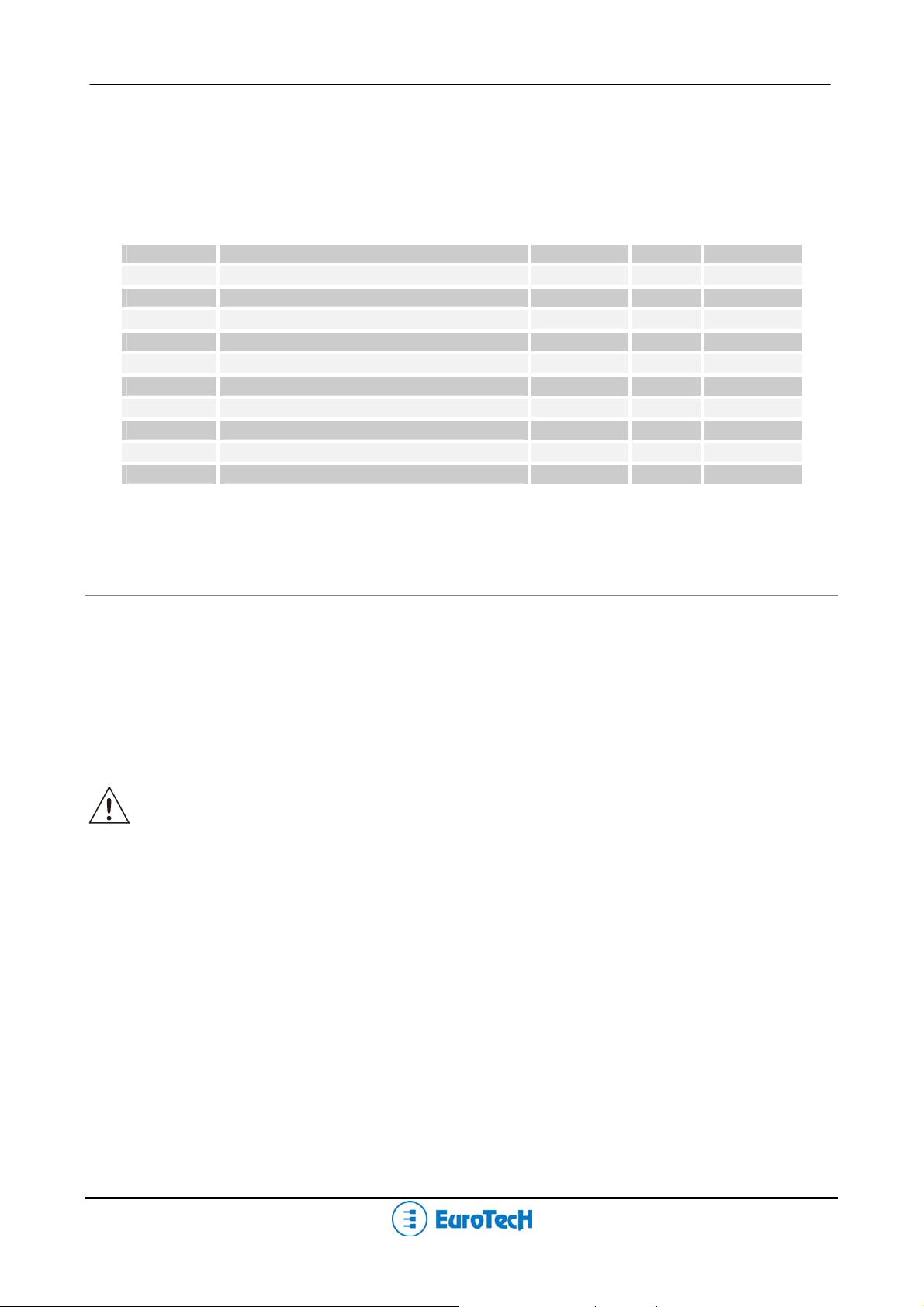
Table 2 lists the name of the connectors with their function:
Table 2. Connector Functions
Connector Function Qty of pins Format Pitch (mm)
J1-J2
J3
J4
J5
J7
J9
J14
J16
J17
J20
ISA BUS (Bottom Side Only)
PCI BUS (Bottom Side Only)
Multifunction, VGA
IDE/DOM
USB 2.0 (Ports 5 and 6)
Aux. power
USB 1.1 (Ports 1 and 2), AUDIO CODEC
USB 2.0 (Ports 1..4)
Serial Ports 1and 2
Fast Ethernet (10/100Mbps)
- - -
- - 18 9x2 2.00
44 22x2 2.00
8 8x1 2.00
12 6x2 2.54
20 10x2 2.00
16 8x2 2.00
18 9x2 2.00
8 8x1 2.00
How to connect the CPU-1461 to other PC/104 & PC/104-Plus devices: the stack assembly
The ISA and PCI Bus connectors of the CPU-1461 are located on the bottom side of the module only, and
are designed to allow the connection on the top position of the stack formed by other PC/104 and/or PC/104Plus devices.
We recommend you to follow the procedure below ensuring that stacking of the modules does not damage
connectors or electronics parts.
Always use appropriate antistatic precautions when handling boards
1. Turn off all power to the PC/104 computer and its peripheral devices.
2. Select and install standoffs to properly position the module o n the PC/104 stack.
3. Remove the module from its antistatic bag.
4. Check that keying pins in the bus connector are properly positioned.
5. Check the stacking order; make sure an XT bus card are not placed between two AT bus cards as
this will interrupt the AT bus signals.
6. Hold the module by its edges and orient it so that the bus connector pins line up with the matching
connector on the stack.
7. Using even pressure press the module onto the PC/104 stack.
14 PC/104-Plus – CPU-1461 Module
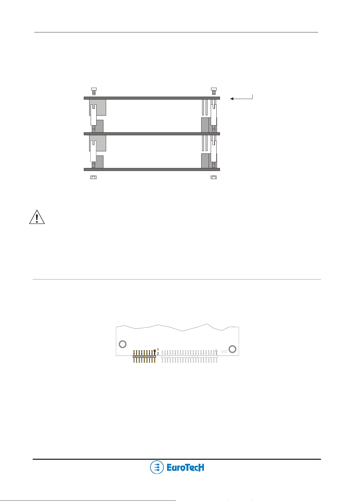
Figure 3 shows a module stack with the CPU-1461 on the top of two PC/104-Plus modules.
If standard PC/104 modules are used in the stack, they must be the lowest modules because they will
normally not include the PCI bus. An adapter module must be used.
CPU-1461
Carrier Module
Figure 3. The Module Stack
Do not force the module onto the stack! Wiggling the module or applying too much pressure
may damage it. If the module does not readily press into place, remove it, check for bent pins
or out-of-place keying pins, and try again.
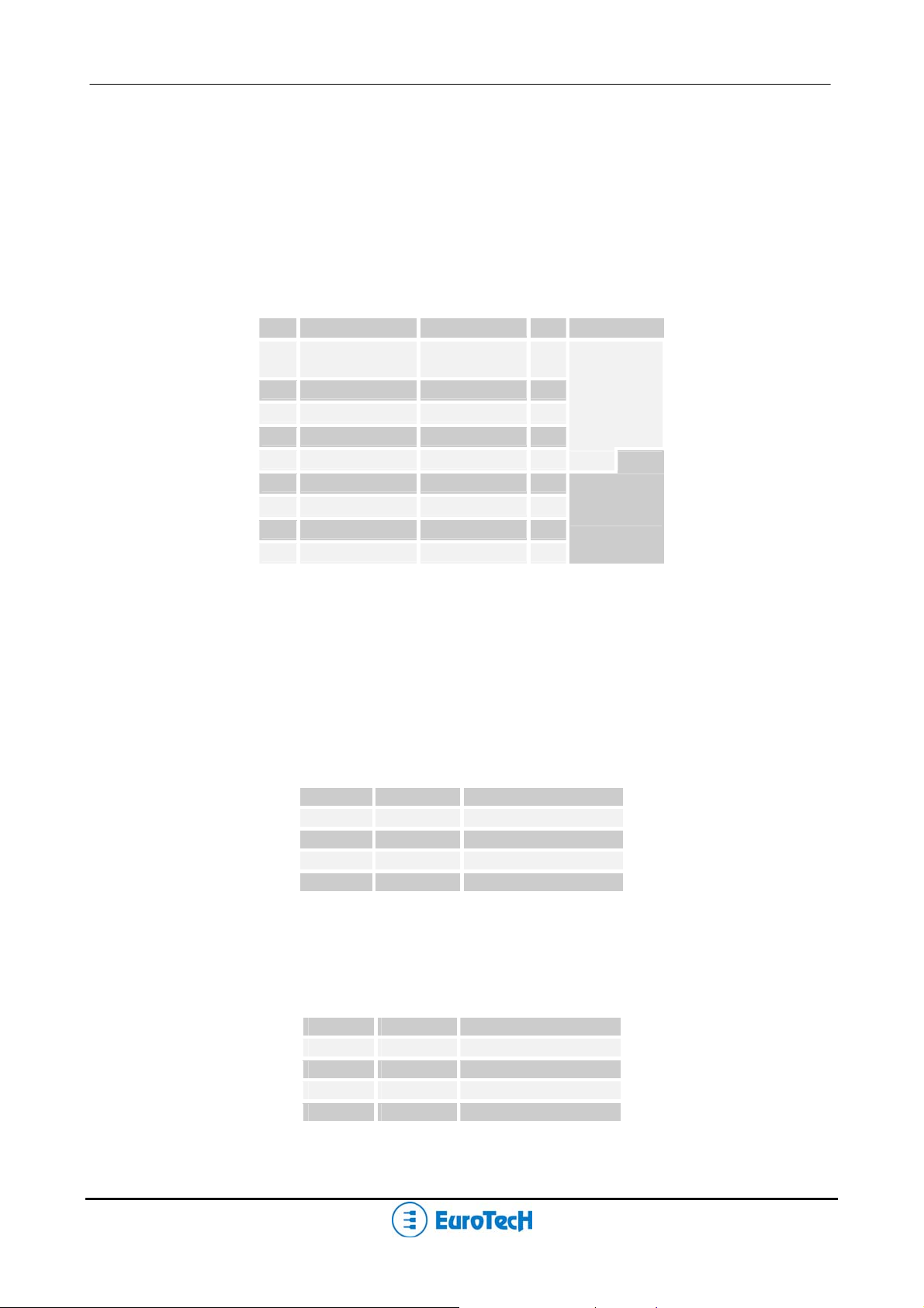
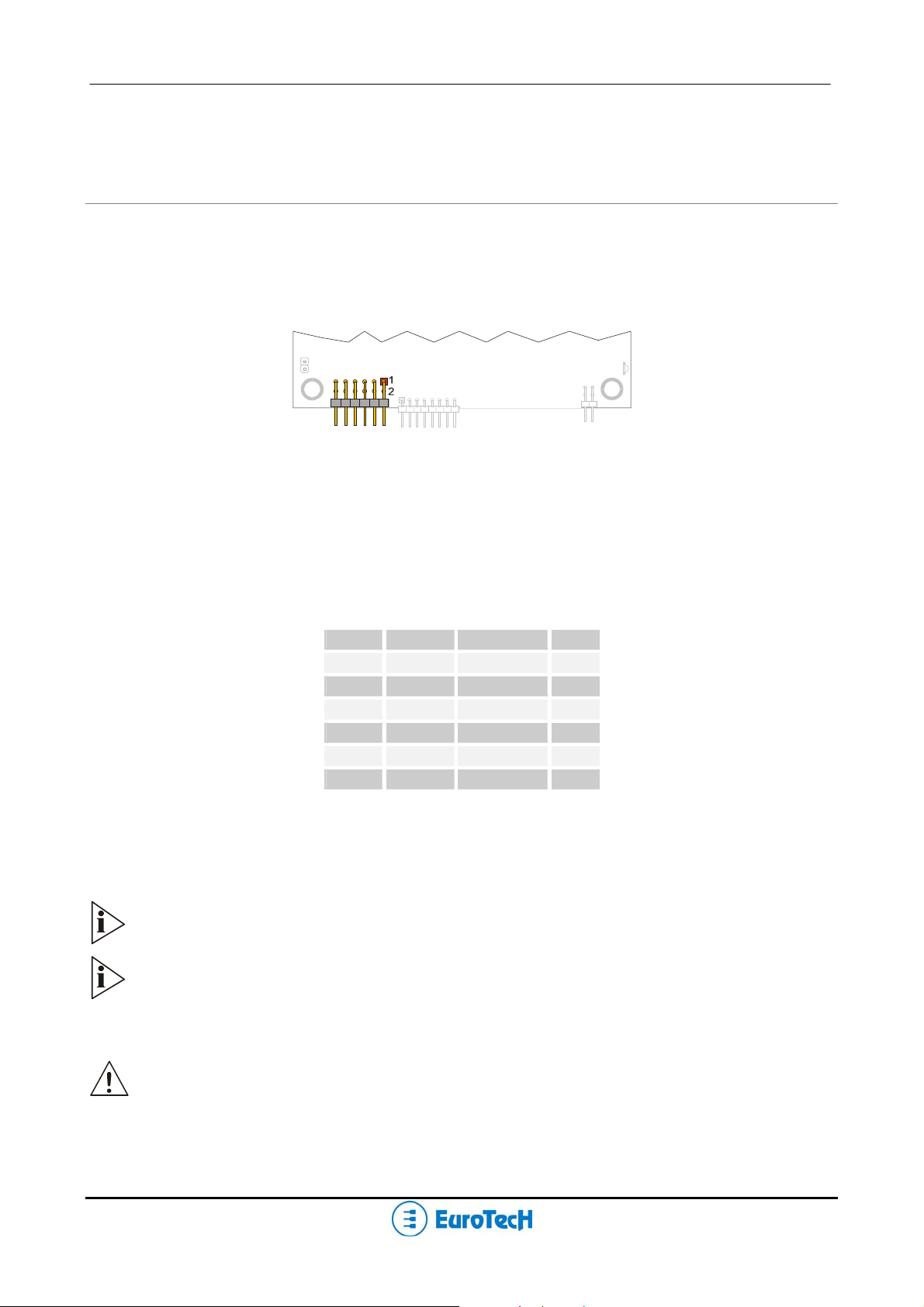
J4 for Multifunction and VGA
This connector enables the connection of a speaker, keyboard, mouse, battery and VGA monitor to the CPU-
1461.
J4
Multifunction, VGA
Figure 4. J4 Connector Layout
The connector implements the following functions:
¾ MULTIFUNCTION SECTION (from pin 1 to pin 9)
Keyboard
PS/2 Mouse
PC/104-Plus – CPU-1461 Module 15
System reset
External battery
Speaker
Power button
¾ VGA monitor (from pin 10 to pin 18)
Table 3 shows the connector pin out.
Table 3. J4 Multifunction/VGA connector
PIN SIGNAL SIGNAL PIN FUNCTION
GND_SRV
1
3
5
7
9
11
13
15
17
KBDAT KBCLK
MSDAT MSCLK
BAT_IN SPKR
RES_PB_IN GND_VGA
HSYNC VSYNC
RED_VGA GREEN_VGA
DDC1_SCL DDC0_SDA
GNDA_VGA BLUE_VGA
VDD_SRV
(+5V)
2
4
6
8
10
12
14
16
18
MULTIF.
VGA
Multifunction Connector Section
This section of the connector implements the following functions:
Keyboard
An AT compatible keyboard can be connected to the module through connector J4. Table 4 lists the
pin-out of connector J4.
Table 4. Keyboard connector table
Pin # Signal Function
1
2
3
4
Mouse Connector Section
A PS/2 compatible mouse can be connected to the J4 connector. Table 5 shows the pin-out for the
mouse
Table 5. J4 for Mouse connector
Pin # Signal Function
1
2
5
6
GND Gro und signa l
+5V Power supply
KBDAT Keyboard data
KBCLK Keyboard clock
GND Ground signal
+5V Power supply
MSDAT Mouse data
MSCLK Mouse clock

16 PC/104-Plus – CPU-1461 Module
System reset
The connection of the multifunction connector pin 9 to ground performs a hardware reset of the
module. It is possible to use an external push-button (normally open) to manually reset the system.
The reset signal is “de-bounced” on the board.
External Battery
Pin 7 of the multifunction connector allows the connection of an external backup battery.
If you connect a battery, then the voltage must be between 3.0V and 3.9V.
This battery is used when the system is powered down to preserve the Real Time Clock data.
The typical battery consumption with the module off is 7uA.
Speaker
A transistor that supplies 0.1W to an external speaker controls these outputs. A transistor amplifier
buffers the speaker signal. Use a small general-purpose 2” or 3” permanent magnet speaker with an
Ω voice coil. The audio output is based on two signals: one come from the output of Timer 2, and
8
the other come from I/O port 61h compliant with the AT Standard.
The Eurotech Multifunction Adapter
The Eurotech Multifunction Adapter simplifies the connection of mouse and keyboard with two PS/2
connectors, a speaker, battery and a reset pushbutton.
Speaker
Battery
J6
To Multif. Conn.
Of CPU Board
(Mouse sign.)
J3
Mouse
J1
J5
Not
used
J2 S1
Keyboard
J4
To Multif. Conn.
of CPU Board
Power Led
Spkr Led
Reset
Pushbutton
Figure 5. Multifunction Adapter (both sides)
PC/104-Plus – CPU-1461 Module 17
BATT_IN (to J4 PIN 7)
9
Table 6. J4 To CPU J4 Connector
PIN # SIGNAL
1
2-8
3
4-10
5
6
7
SPKR (to J4 PIN 8)
+5V (to J4 PIN 2)
RES_PB_IN (to J4 PIN 9)
N.C.
KBDAT (to J4 PIN 3)
KBCLK (to J4 PIN 4)
GND (to J4 PIN 1)
Table 7. J6 To CPU J4 Connector (Mouse
signals)
PIN # SIGNAL
1
2
3
4
+5V (to J4 PIN 2)
MSCLK (to J4 PIN 6)
GND. (to J4 PIN 1)
MSDAT (to J4 PIN 5)
VGA Section
The CPU-1461 integrates a high-performance 2D graphics accelerator
Supported CRT-VGA Video Resolutions
Table 8 shows supported CRT Display Modes
1
Table 8. Partial list of Display Modes Supported
Resolution
640x480
8-bitIndexed 16-bit 24-bit
320x200 70 70 70
320x240 70 70 70
352x480 70 70 70
352x576 70 70 70
400x300 70 70 70
512x384 70 70 70
640x400 70 70 70
640x480 60, 70, 72, 75, 85 60, 70, 72, 75, 85 60, 70, 72, 75, 85
720x480 75, 85 75, 85 75, 85
720x576 60, 75, 85 60, 75, 85 60, 75, 85
800x600 60, 70, 72, 75, 85 60, 70, 72, 75, 85 60, 70, 72, 75, 85
1024x768 60, 70, 72, 75, 85 60, 70, 72, 75, 85 60, 70, 72, 75, 85
1152x864 60, 70, 72, 75, 85 60, 70, 72, 75, 85 60, 70, 72, 75, 85
1280x720 60, 75, 85 60, 75, 85 60, 75, 85
1280x960 60, 75, 85 60, 75, 85 60, 75, 85
1280x1024 60, 70, 72, 75, 85 60, 70, 72, 75, 85 60, 70, 72, 75, 85
Bits Per Pixel (frequency in Hz)
18 PC/104-Plus – CPU-1461 Module
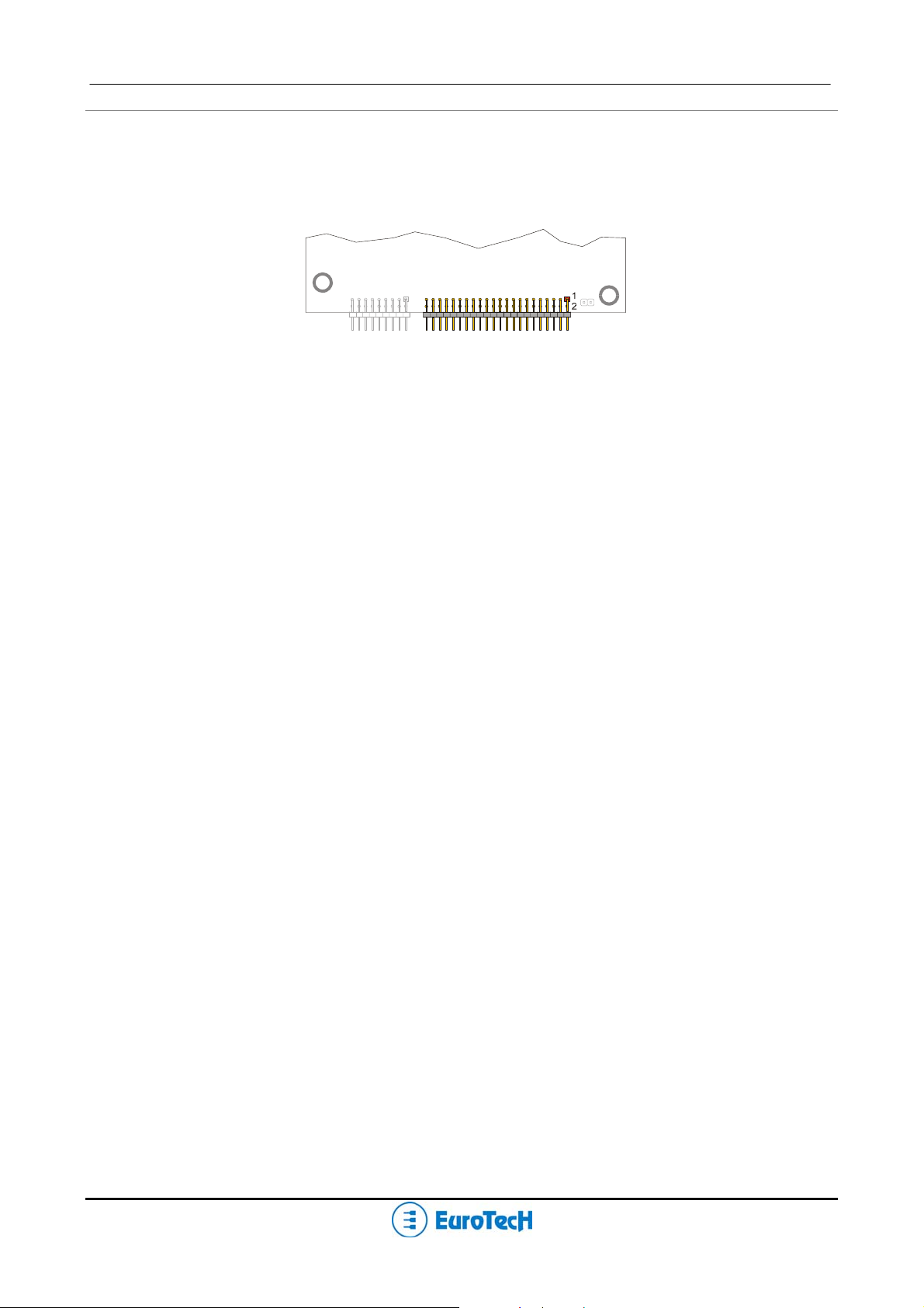
J5 IDE Connector
The CPU-1461 module provides an interface for up to two Integrated Device Electronics (IDE) hard disk
drives on connector J5.
J5
IDE/DOM
Figure 6. J5 Connector layout
To install the hard disk, perform the following operations:
¾ Hardware installation. Connect the hard disk to the module using a data cable, and then connect the
hard disk to the power supply according to the device’s specifications. Make sure that pin 1 of connector
J5 and pin 1 of the drive or drives are correctly connected. Pin 1 of the interface cable is usually
indicated by a stripe along the edge of the cable. If two hard disks need to be connected, they must be
configured for common operation (i.e. master/slave or cable select connection).
¾ IDE BIOS Setup. The hard disk parameters can be configured using the Setup program. If the hard disk
is connected to the module without setup configuration or with a wrong setup configuration, a time-out of
a few minutes occurs.
¾ Software initialization for specific operating systems. Refer to the OS documentation.
PC/104-Plus – CPU-1461 Module 19
J7 for USB 2.0 (Ports 5 and 6)
J7 is used for USB 2.0, ports 5 & 6. Each port can supply up to 2A
J7
USB 5, 6
Figure 7. J7 Connector Layout
Table 9. J7 Connector pin out
PIN# SIGNAL FUNCTION
1
2
3
4
5
6
7
8
VDD_USB5
USB5-
USB5+
GND_USB_5
VDD_USB_6
USB6-
USB6+
GND_USB_6
USB 5
USB 6
Note: To establish a USB connection, no transceiver is required.
20 PC/104-Plus – CPU-1461 Module
J9 Auxiliary Power Connector
J9 is an auxiliary power connector and can be used to power the module as an alternative to the PC/104Plus bus.
J9
Auxiliary
Power
Figure 8. J9 Connector layout
Table 10 shows the pin out for J9.
Table 10. J9 Auxiliary Power Connector
PIN # SIGNAL SIGNAL PIN #
1
3
5
7
9
(1)
+5VSB: +5 Volts-Always from the ATX Power supply
(2)
PSON#: Power-On command to ATX Power supply
11
GND VDD
N.C. +12v
-5V
-12V
GND VDD
N.C. PWRBTN#
+5VSB
(1)
PSON#
2
4
6
8
10
(2)
12
Power button (input)
If the soft power management is enabled, a low signal in this pin turns the system on or off.
Note. The VSB (Volt Stand-By) voltage is useful for Power management applications only.
Note. The +12VDC and -5VDC voltages are neither used nor generated by the CPU-1461 module:
they are only conveyed on the PC/104-Plus bus (connector J1) and can be used by other
devices or modules that are stacked onto the CPU module.
WARNING! IMPROPER CONNECTION OF THE POWER SUPPLY WILL RESULT IN SERIOUS
DAMAGE TO THE MODULE.
PC/104-Plus – CPU-1461 Module 21
J14 for USB 1.1 (Ports 7 and 8) and Audio-CODEC
J14 is used for USB 1.1, ports 7 & 8 and the Audio CODEC.
1
2
J14
Figure 9. J14 Connector Layout
It implements the following functions:
¾ CODEC Audio port
¾ USB 1.1 port 7
¾ USB 1.1 port 8
Table 11 shows the J14 connector pin out.
Table 11. J14 Connector pin out
PIN # SIGNAL SIGNAL PIN # PORT
1
3
5
7
9
11
13
15
17
19
SPKR SDIN1
SDOUT CDC_EN#
GND GND
SDIN0 BITCLK
RST SYNC
GND
USB7- USB8-
USB7+ USB8+
GND VDD
GND VDD
USB Over
Current1#
2
4
6
8
10
12
14
16
18
20
Audio
Codec
USB
7, 8
The Eurotech USB & AC97-Audio Codec Adapter
Before using a USB and/or an Audio Device, the Eurotech USB/AC97-Audio Codec Adapter must be
connected to the CPU board. The connection between the Eurotech adapter and the CPU board is
established by a cable set provided with the adapter.
Figure 10 shows this adaptor.
 Loading...