

Page 1

Dat as h eet
RFID1 3 R0 1
1 3 .5 6 MH z Mu l t is t an dar d RFI D t r a n s ceiver mod ul e f o r Zypad WL 1 x1 x
ETH_RFID13 R01_DS220507
Eu r o t ec h S .p.A .
e-mai l : s al es @eu r o t ech .i t
h t t p://w ww .eur o t e c h .it
Introduction
The module is a multistandard RFID transceiver for use with
the Zypad WL1x1x wearable computer family. It works at
13.56 MHz and supports the following standards: ISO
14443A, ISO 14443B and ISO 15693.
The interface with the Zypad main unit is made through the
serial port COM2.
FCC information and compliance
This device complies with Part 15 of the FCC Rules. Operation is subject to the following two conditions:
(1) this device may not cause harmful interference
(2) this device must accept any interference received, including interference that may cause undesired operation.
Changes or modifications not expressly approved by the party responsible for compliance could void the user's authority
to operate the equipment.
Instruction manual for FCC ID labeling
Module type: <RFID Transceiver Module> RFID 13
FCC-ID : UKMRFID13
This intends to inform you how to specify the FCC ID of our <RFID Transceiver Module> Module RFID13 on your
final product.
Based on the Public Notice from FCC, the product into which the our transmitter module is installed must
display a label referring to the enclosed module.
Example of label: “Contains FCC ID: UKMRFID13”
Main features
SMT (Surface Mount Technology) connections
Firmware upgradeable via serial interface
Possibility to connect an external SAM (Secure Access Module)
Page 2
RFID 1 3 R 0 1 Dat as h eet
ETH_RFID13 R01_DS220507
EuroTecH SpA
a member of the Eurotech Group
Via Fratelli Solari, 3/a
33020 Amaro (UD) - Italy
E-mail: sales@eurotech.it
Tel. +39 0433 485 411 - Fax. +39 0433 485 499
Note: The information in this document is subject to change without notice and should not be construed as a commitment by EuroTecH S.p.A.
While reasonable precautions have been taken, EuroTecH S.p.A. assumes no responsibility for any error that may appear in this document.
All trademarks or registered trademarks are the properties of their respective companies.
DIGITAL TECHNOLOGIES FOR A BETTER WORLD
www.eurotech.it
Parameter
Value
Notes
Input power supply
+3.3 Vdc @ 100mA (max)
Serial interface line
+3.3 Vdc
Serial communication characteristics:
Bit per second: 115200
Parity: None
Data bits: 8
Stop bits: 1
Stand by input line
+3.3 Vdc
Active low signal
Hardware reset input line
+3.3 Vdc
Active low signal
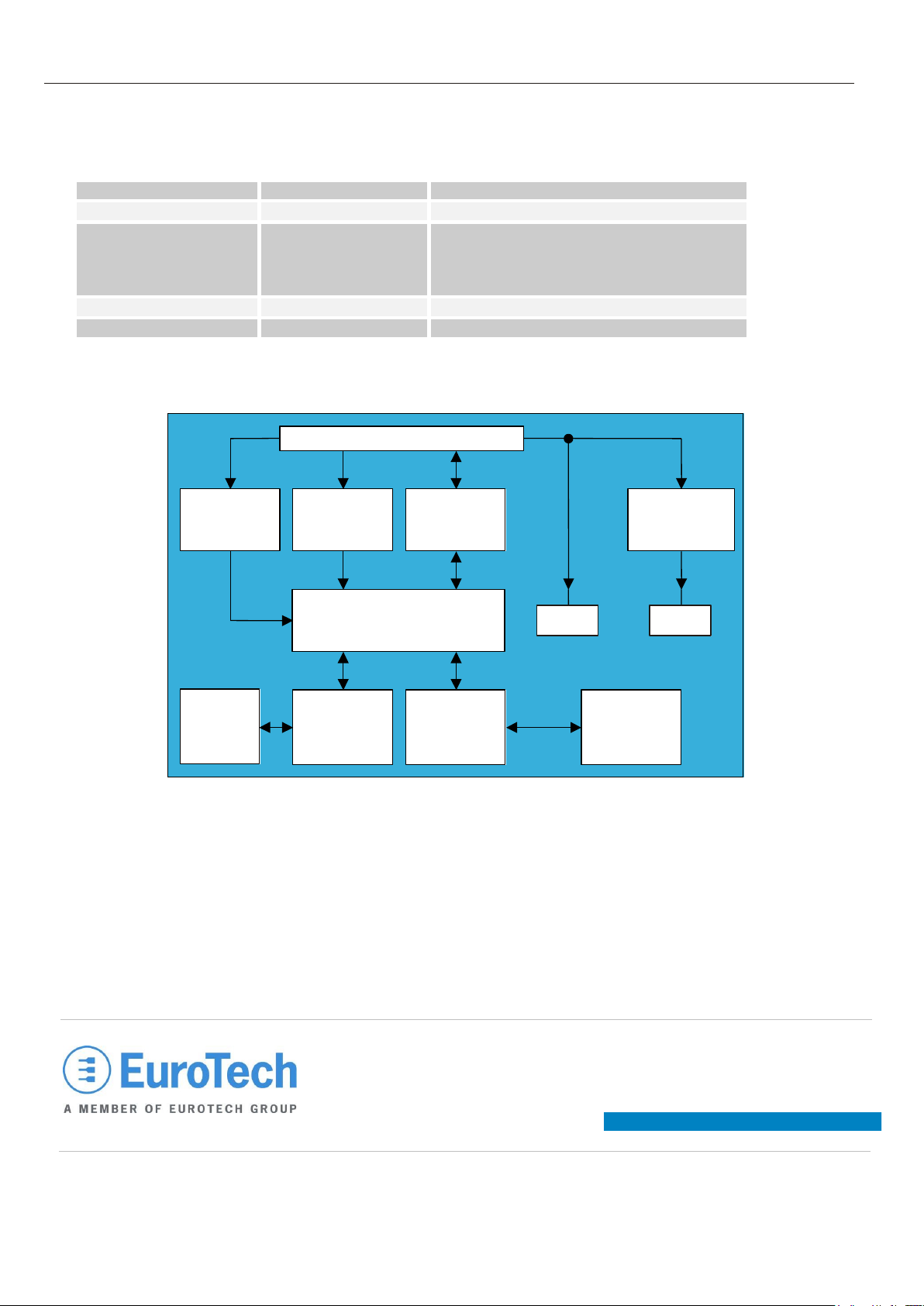
Main connections
Stand by
Input
(3.3 Vdc level)
Reset
Input
(3.3 Vdc level)
ATMEL
AT91SAM7S64
Microprocessor
Connector
to SAM
Module
SAM
Module
Interface
13.56 MHz
RF Interface
13.56 MHz
PCB
Antenna
Serial
Interface
(3.3 Vdc level)
Step up
3.3 Vdc - 5 Vdc
3.3 Vdc
5 Vdc
Electrical features
Block diagram
Page 3

Tec h n ic a l D a t a s h eet
L MS -Zypad-1 x 1 x
1 3 .5 6 MH z Mu l t is t an d a r d RFID t r a ns c eiv er f o r Zy p a d WL 1 x 1 x
ETH_LMS-Zypad-1x1x_TDS220507
Eur o t ec h S.p .A.
e-mail : sal es @eur o t ech .it
h t t p://www.e ur o t ec h .it
Functional description
Tag
Made by
Standard
Uid length
MIFARE 1k
Philips
14443A
4 bytes
MIFARE 4k
Philips
14443A
4 bytes
MIFARE ultralight
Philips
14443A
7 bytes
ICODE2
Philips
15693
8 bytes
TAG-IT HF-I
Texas
15693
8 bytes
EM4135
MEM
15693
8 bytes
LRI64 / LRI512
ST
15693
8 bytes
SR176
ST
14443B
8 bytes
Signal
Description
WL1x1x signal
+3.3 Vdc
Input power supply
VDD
GND
Ground signal
GND
IN1
Stand by input (active low signal)
GPIO
IN2
Reset input (active low signal)
RESET
GND
Ground signal
GND
RX
Serial Input (3.3 Vdc line)
TX
TX
Serial Output (3.3 Vdc line)
RX
The device reads and writes transponders at a frequency of 13.56 MHz and supports the ISO 14443A, ISO14443B and
ISO 15693 standards.
The microprocessor is an ARM ATMEL AT91SAM7S64.
The RF interface is based on the PHILIPS CLRC632 ‘Multiple contactless reader IC’ controller.
The SAM interface is formed by the ON NCN4555 ‘SIM card power supply / level translator’ circuit.
The power voltage is 3.3 Vdc and is used to supply the digital devices (such as: microprocessor and I/O). An internal
MAX1724 DC/DC step-up converter allows you to obtain a +5V voltage to supply RF devices. A 1.8 Vdc voltage
regulator is integrated inside the microprocessor and supplies the ARM core.
The RF antenna is integrated on the PCB (Printed Circuit Board) of the module.
The reset signal operates at a hardware level.
The stand by signal is managed at a firmware level.
The following table lists the supported tags:
The following table lists the interfacing signals:
 Loading...