

Page 1

PCN
Passenger & People Counter
Rev
USER MANUAL
-1001
4.0 – 23 December 2011 – PCN-1001_UserMan_En_4.0
Page 2

© 2011 Eurotech
Trademarks
REVISION
DESCRIPTION
DATE
• Joined together the programming and the Installation
manuals into “PCN-1001_Manual_2.0”
2.1
• Corrected M1 & M2 pinouts
November 2007
2.2
Minor changes
November 2007
Added cable kit note on pages 20 and 21
table on pag76
53 to 55
• Manual layout update
• WinClient screenshots updated to rev 2.3.3
• Updated RS485 information on page 67 and 68
2.8
Small corrections on pages 11 and 68
March 2010
2.9
Updated WinClient features to reflect version 2.3.5
May 2010
Updated WinClient features to reflect version 2.3.6
on page 61
3.2
• Minor changes
April 2011
General contents review
All trademarks both marked and unmarked appearing in this document are the property of their respective
owners.
Revision history
2.0
2.3
2.4
2.5
2.6
2.7
3.0
3.1
4.0
•
• Added “The maximum suggested number of Counters to
connect together is 5” on note on page 19
•
• Added Notes on page 49
• Removed “testin0/1” command from “The RS485 protocol”
• Relevant changes applied to pages: 15, 36, 40, 46 to 48,
• “Installing/Updating the software” paragraph updated
• Updated CRC16 Algorithm on page 80
•
•
• General contents review
•
• Added paragraph Cleaning on page 7
• Updated paragraph The “Wide-Gate” tab on page 63
• Updated paragraph Notes about the Digital I/O interface
•
September 2007
February 2008
April 2008
August 2008
May 2009
February 2010
June 2010
September 2010
23 December 2011
Page 3

Table of contents PCN-1001 User manual
PCN
Table of contents
Trademarks .................................................................................................................................................................. 2
Revision history ........................................................................................................................................................... 2
Table of contents .......................................................................................................................................................... 3
Important user information .......................................................................................................................................... 7
Alerts that can be found throughout this manual ......................................................................................................... 7
Safety notices and warnings ........................................................................................................................................ 8
Do not operate in an explosive atmosphere .......................................................................................................... 8
Antistatic precautions ............................................................................................................................................. 8
Connection to power supply or other devices ........................................................................................................ 8
Installation .............................................................................................................................................................. 9
Ventilation............................................................................................................................................................... 9
Maintenance ........................................................................................................................................................... 9
Cleaning ................................................................................................................................................................. 9
Life support policy ...................................................................................................................................................... 10
Warranty .................................................................................................................................................................... 10
CE Notice ................................................................................................................................................................... 10
WEEE ........................................................................................................................................................................ 10
RoHS ......................................................................................................................................................................... 10
Technical assistance ................................................................................................................................................. 11
Transportation ...................................................................................................................................................... 11
Device labelling .................................................................................................................................................... 11
Conventions and definitions used within this Manual ................................................................................................ 12
The “Mode” of the register:................................................................................................................................... 12
Hexadecimal numbering: ..................................................................................................................................... 12
Control Unit, Host PC ........................................................................................................................................... 12
PCN-1001, Device, Counter, Master, Slave ........................................................................................................ 12
ART 1 – INTRODUCTION ................................................................................................................................................. 13
P
Contents of the box .................................................................................................................................................... 15
PCN-1001 general description ................................................................................................................................... 16
Front interfaces. The service panel ........................................................................................................................... 18
LED indicator assignment .................................................................................................................................... 18
Notes about the Mini USB port ............................................................................................................................ 18
Rear interfaces .......................................................................................................................................................... 19
Power Supply Specifications ..................................................................................................................................... 20
Mechanical Characteristics ........................................................................................................................................ 20
P
ART 2 – PCN-1001 INSTALLATION PROCEDURE ............................................................................................................. 21
Step 1: Find the best mounting location ................................................................................................................... 23
The PCN-1001 field of view and the Detection area ................................................................................................. 24
The PCN’s field of view ........................................................................................................................................ 24
The Detection area ............................................................................................................................................... 25
Number of PCN-1001 devices required .................................................................................................................... 27
Example ............................................................................................................................................................... 27
How to connect one PCN-1001 ........................................................................................................................... 28
How to connect two PCN-1001 devices in Wide-gate configuration ................................................................... 29
-1001_UserMan_En_4.0
3
Page 4

Table of contents PCN-1001 User manual
1001_UserMan_En_4.0
How to connect three or more PCN-1001 devices in Wide-gate configuration ................................................... 30
Note about PCN-1001 devices connected in Wide-gate configuration ................................................................ 31
Step 2: Install a PCN-1001 .......................................................................................................................................... 33
Step 2.1: Connect the rear side interfaces and adjust the angle of the front panel .................................................. 33
1: Loosen the front panel to simplify the cabling procedure: ............................................................................... 33
2: Connect all the interfaces and prepare the power connections to M1 ............................................................. 33
3: Adjust the angle of the front panel and secure the front panel ........................................................................ 34
Note about installing 2 or more PCN-1001 in Wide-gate configuration..................................................................... 34
Step 2.2: Fix the PCN-1001 to the ceiling ................................................................................................................. 35
Step 3: Configure the network between PCN-1001 and Host PC ........................................................................... 36
Step 3.1: Turn on the PCN-1001power ..................................................................................................................... 36
Step 3.2: Connect the PCN-1001 with the Host PC .................................................................................................. 36
Step 3.3: Configure the network on the Host PC ...................................................................................................... 37
Step 3.4: Configure the TCP/IP Properties ............................................................................................................... 38
Step 3.5: Configure the Host PC firewall ................................................................................................................... 39
Step 4: Use WinClient to network PCN-1001 & Host PC ......................................................................................... 40
Step 4.1: Set the main parameters in the “Controls” tab ........................................................................................... 41
1: Set the “Date and Time settings” ..................................................................................................................... 41
2: Set the “Distance Configuration” ...................................................................................................................... 41
3: Set the “Light intensity” .................................................................................................................................... 41
4: Set the “In/Out direction” .................................................................................................................................. 42
5: Set the “Door kind” ........................................................................................................................................... 42
6: Set the “Door threshold” ................................................................................................................................... 42
7: Use the “Scene background” button to acquire and store the background ..................................................... 43
Step 5: Use WinClient to test the tracking of people .............................................................................................. 45
Example of counting .................................................................................................................................................. 46
How the threshold works when using digital inputs ................................................................................................... 47
P
ART 3 – THE PCN-1001 SOFTWARE .............................................................................................................................. 49
Install/update the software ......................................................................................................................................... 51
The pcn-1001-Imgserver ........................................................................................................................................... 51
The pcn-1001-demo-win32 ........................................................................................................................................ 51
The WinClient ....................................................................................................................................................... 51
The RS485_GUI ................................................................................................................................................... 51
Install/update the software on the Host PC ............................................................................................................... 52
Install / Update WinClient and RS485_GUI on the PCN-1001 ............................................................................ 52
Updating Imgserver on the PCN-1001 ................................................................................................................. 54
Know WinClient ........................................................................................................................................................... 57
The drop-down list ................................................................................................................................................ 58
The Start and Stop buttons .................................................................................................................................. 58
PCN Configuration Files management (PCF) ...................................................................................................... 58
The status bar ...................................................................................................................................................... 59
The tabs ............................................................................................................................................................... 60
The “Controls” tab ...................................................................................................................................................... 61
The “Date and Time settings” panel ..................................................................................................................... 61
The “Distance Configuration” panel ..................................................................................................................... 61
The “Light intensity” panel .................................................................................................................................... 61
The “In/Out direction” panel ................................................................................................................................. 62
The “Door kind” panel .......................................................................................................................................... 62
The “Door threshold” panel .................................................................................................................................. 62
The “Data records” panel ..................................................................................................................................... 63
4
PCN-
Page 5

Table of contents PCN-1001 User manual
PCN
The “Scene background” button .......................................................................................................................... 65
The “Reset counters” button ................................................................................................................................ 66
The “Restore Factory Settings” button ................................................................................................................. 66
The “System update” button................................................................................................................................. 66
The “I/O Settings” tab ................................................................................................................................................ 67
The “Optocoupled I/O functions” panel ................................................................................................................ 67
The “Optocoupled I/O test” panel ......................................................................................................................... 68
Notes about the Digital I/O interface .................................................................................................................... 69
Note: How to simulate a digital input .................................................................................................................... 70
The “RS485 Setup” panel .................................................................................................................................... 70
The “Wide-Gate” tab .................................................................................................................................................. 71
Setting up the PCN-1001 devices for the Wide-Gate configuration .................................................................... 71
The “Advanced (1/2)” tab ........................................................................................................................................... 73
“No Tracking Zone” panel .................................................................................................................................... 73
“Single Way Tracking” panel ................................................................................................................................ 75
“PCN-1001 System diagnostic” panel .................................................................................................................. 75
“Use Move detection” panel ................................................................................................................................. 76
“Time Background” panel ..................................................................................................................................... 77
The “Advanced (2/2)” tab ........................................................................................................................................... 78
“Stairs Upgrade” panel ......................................................................................................................................... 78
Test an RS485 connection and use the RS485_GUI ................................................................................................ 79
Introduction ................................................................................................................................................................ 79
Notes about the RS485 serial bus for development purposes .................................................................................. 80
Example of RS485 network ....................................................................................................................................... 81
Configure the RS485 port of the PCN-1001 .............................................................................................................. 82
Start the RS485_GUI. Configure the RS485 port of the Host PC ............................................................................. 83
“Recipient” and “Polling” panels ........................................................................................................................... 84
“System Info” panel .............................................................................................................................................. 85
“IP Address” panel ............................................................................................................................................... 85
“Date and Time settings” panel ............................................................................................................................ 85
“System Update” panel ........................................................................................................................................ 85
“Optocoupled Inputs functions” panel .................................................................................................................. 86
“Optocoupled outputs open time” panel ............................................................................................................... 86
“Log” panel ........................................................................................................................................................... 86
The communication protocol ..................................................................................................................................... 87
Polling ................................................................................................................................................................... 88
Scenarios ............................................................................................................................................................. 88
The DATA field ..................................................................................................................................................... 89
Example 1: setting the LED intensity to 100 ........................................................................................................ 90
Example 2: requesting the kernel version installed in the PCN-1001 .................................................................. 90
Commands availability ......................................................................................................................................... 91
CRC16 Algorithm ....................................................................................................................................................... 95
APPENDIX .................................................................................................................................................................... 97
Note for mounting the front panel with angles from 20° up to 45° ........................................................................ 99
PCN-1001 Cable kits ................................................................................................................................................. 100
CBL-1001-00 cable kit ............................................................................................................................................. 100
7030000330L Multifunction Cable ..................................................................................................................... 100
Male USB Mini-B to Male USB Type “A” Cable ................................................................................................. 101
Male USB Type “A” to Female USB Type “A” Extension Lead .......................................................................... 101
703704001SL Adapter (Male USB Type “A” to Male DB9 for RS485 Cable) .................................................... 102
CBL-1001-01 cable kit ............................................................................................................................................. 103
7010000108L Cable for direct connection ......................................................................................................... 103
-1001_UserMan_En_4.0
5
Page 6

Table of contents PCN-1001 User manual
1001_UserMan_En_4.0
Example of direct connection using the CBL-1001-01 ....................................................................................... 104
CBL-1001-02 cable kit ............................................................................................................................................. 105
7030000331L Cable for Multiple Connection ..................................................................................................... 105
Example of direct connection using the CBL-1001-02 ....................................................................................... 106
Rear interfaces .......................................................................................................................................................... 107
Power Supply Specifications ................................................................................................................................... 108
Mechanical Characteristics ...................................................................................................................................... 108
PCN-1001 Logon ....................................................................................................................................................... 109
Troubleshooting ........................................................................................................................................................ 111
Standards Compliance ............................................................................................................................................. 113
Cut-out template ........................................................................................................................................................ 115
Notes ........................................................................................................................................................................ 117
6
PCN-
Page 7

Important user information PCN-1001 User manual
PCN
Symbol
Meaning
Important user information
Please carefully read and understand the instructions in this manual before using the device.
Whenever you have any doubts regarding the operation of this device, first consult this manual, and then if you
are still unable to resolve your issue, contact the Eurotech Technical Support Team for assistance.
To lower the risk of personal injury, electric shock, fire or damage to equipment, you must observe the
following precautions, as well as using good technical judgment, whenever installing or using this
device.
Eurotech has made every effort to ensure the accuracy of this document; however, Eurotech assumes no liability
resulting from any error/omission in this document, or from the use of the information contained herein.
Eurotech reserves the right to revise this document or to make changes to its content at any time without any
obligation to notify any person of such revisions or changes.
Alerts that can be found throughout this manual
DANGER!
Information highlighting potential electrical shock hazards:
• Personal injury or death could occur.
• Damage to the system, connected peripheral devices, or software could occur.
Appropriate safety precautions should always be used; these should meet the requirements set out for the
environment that the equipment will be deployed in.
WARNING!
Information highlighting potential hazards:
• Personal injury or death could occur.
• Damage to the system, connected peripheral devices, or software could occur.
Appropriate safety precautions should always be used; these should meet the requirements set out for the
environment that the equipment will be deployed in.
NOTE
These will highlight important features or instructions.
-1001_UserMan_En_4.0
7
Page 8

Important user information PCN-1001 User manual
1001_UserMan_En_4.0
Safety notices and warnings
Users must observe the following safety precautions during all phases of operation, service, and repair of the
device. Failure to comply with these precautions or with specific warnings elsewhere in this manual violates
safety standards of design, manufacture, and intended use of the device.
Eurotech assumes no liability for the customer’s failure to comply with these requirements.
The safety precautions listed below represent warnings of certain dangers of which Eurotech is aware. You, as
the user of the device, should follow these warnings and all other safety precautions necessary for the safe
operation of the device in your operating environment.
Do not operate in an explosive atmosphere
WARNING!
Do not operate the equipment in the presence of flammable gases or fumes. Operation of any
electrical equipment in such an environment constitutes a definite safety hazard.
Antistatic precautions
WARNING!
To avoid ESD (Electro Static Discharge) damage, always use appropriate antistatic precautions
when handing any electronic equipment.
Connection to power supply or other devices
• To avoid injuries, always disconnect power and discharge circuits before touching them.
• Only start the device with a power supply that meets the requirements stated on the voltage label. In
case of uncertainties about the required power supply, please contact the Eurotech Technical Support
Team or the electricity authority
• Before connecting other equipment carefully read any supplied instructions
• Always disconnect the power before connecting or disconnecting cables
• Do not perform connections with wet hands
• Check any power cords for damage before use
• Use certified power cables. The power cable must meet the requirements (voltage and current) of the
device.
• Position cables with care. Avoid positioning cables in places where they may be trampled on or
compressed by objects placed on them. Take particular care of the plug, power-point and outlet of
power cable
• Avoid overcharging any power outlets
• Only apply power to the device or connected equipment after checking that all the above conditions
have been met
8
DANGER!
Before applying power to the system, thoroughly review all installation, operation, and safety
instructions.
Failure to install the system power supply correctly or to follow all operating instructions correctly
may create an electrical shock hazard, which can result in personal injury or loss of life, and/or
damage to equipment or other property
PCN-
Page 9

Important user information PCN-1001 User manual
PCN
WARNING!
Do not operate the device near heat sources or flames.
WARNING!
• Do not block any ventilation openings
WARNING!
Do not use detergents, aerosol sprays, solvents or abrasive sponges
WARNING!
to stop any particulates from entering.
Installation
• Verify that the mounting location can withstand the added loads caused by the addition of the
device, it should be firmly secured so that it will not cause any potentially hazardous
situations (e.g. falling down due to vibration or shock)
•
NOTE:
If the device must be moved from one place to another with different ambient temperatures, ensure sufficient
time for the temperature of the device to stabilize before repowering.
Ventilation
Ensure adequate ventilation to avoid overheating, Eurotech suggests the following steps:
• When installing the device within a cabinet, rack or other enclosed space, be sure to leave
sufficient space to allow adequate air circulation
Maintenance
DANGER!
• Never open, dismantle or repair the device!
• For your maintenance or repair requirement please contact a qualified Eurotech engineer.
If the device does not function correctly and you are unable to find a solution, feel free to contact
the Eurotech Technical Support Team.
If the equipment does not work properly, especially if smells unusual, unplug it immediately and contact Technical
Support Eurotech (see fourth cover of this manual for details).
Cleaning
When cleaning the device, remember to:
• Ensure sufficient ESD protection during the cleaning process
• Remove any power from the device
• Use a dry cloth to remove dust and fingerprints from the external casing
•
To clean the lenses:
1. Use a blower to remove any dust
2. Use water-based, non-flammable, glass/plastic cleaner products to remove all types of
dirt; grease, oil, nicotine etc. from the lenses
3. Gently wipe the lenses with a lint-free cloth.
The PCN-1001 should not be used for extended periods of time with the service plate removed.
Doing so can cause dust and other particulates to enter the system thus causing degradation to the
optics.
If it is necessary to have extended access to the Mini-USB connector, take appropriate precautions
-1001_UserMan_En_4.0
9
Page 10

Important user information PCN-1001 User manual
1001_UserMan_En_4.0
This product is marked CE.
The use of the following symbol, attached to the equipment, packaging, instruction
Life support policy
WARNING!
Users must not use Eurotech products as critical components of life support devices or systems
without the express written approval of Eurotech.
Warranty
Please contact your local Eurotech Sales Office for detailed warranty terms and conditions.
Refer to the back covers of this manual for full contact details.
CE Notice
The CE Mark on the product indicates that the system has been tested and conforms to
the provisions of the 2004/108/EC Electromagnetic Compatibility (EMC) Directive and the
2006/95/EC Low Voltage Directive (LVD).
Eurotech shall not be liable for use of our products with equipment (i.e., power supplies,
personal computers, etc.) that are not CE marked and that do not meet the PCN-1001
technical requirements indicated in this manual.
WEEE
The information below complies with the regulations set out in the 2002/96/EC directive, subsequently
superseded by 2003/108/EC. It refers electrical and electronic equipment and the waste management of such
products.
When disposing of a device, including all of its components, subassemblies and materials that are an integral part
of the product, you should consider the WEEE directive.
literature, or the guarantee sheet, states that the device has been marketed after August
13th 2005, and implies that you must separate all of its components when possible, and
dispose of them in accordance withal waste disposal legislations:
• Because of the substances present in the equipment, improper use or disposal of the refuse can cause
damage to human health and the environment.
• With reference to WEEE, it is compulsory not to dispose of the equipment with normal urban refuse; an
arrangement for separate collection and disposal is essential.
• To avoid any possible legal implications users should contact the local waste collection body for full recycling
information.
RoHS
This device, including all the components, subassemblies and the consumable materials that are an integral part
of the product, have been manufactured in compliance with the European directive 2002/95/EC known as the
RoHS directive (Restrictions of the use of certain Hazardous Substances). This directive targets the reduction of
certain hazardous substances previously used in electrical and electronic equipment (EEE).
10
PCN-
Page 11

Important user information PCN-1001 User manual
PCN
Technical assistance
For any technical questions, or if you cannot isolate a problem with your device, or for any enquiry about repair
and returns policies, feel free to contact your local Eurotech Technical Support Team.
See the back cover for full contact details.
Transportation
When transporting any module or system, for any reason, it should be packed using anti-static material and
placed in a sturdy box with enough packing material to adequately cushion it.
Warning:
Any product returned to Eurotech that is damaged due to inappropriate packaging will not be
covered by the warranty!
Device labelling
On the rear side of the device you can find a label displaying the following information:
A
Model Number
B
Serial Number
C
Power Requirements
-1001_UserMan_En_4.0
11
Page 12

Important user information PCN-1001 User manual
1001_UserMan_En_4.0
SYMBOL / TEXT
DEFINITION
RW
Readable and Writable register
RO
Read only register
W
R
Meaning of the register when read
Conventions and definitions used within this Manual
The following conventions and definitions are used throughout this manual:
The “Mode” of the register:
Meaning of the register when written
Hexadecimal numbering:
Hexadecimal numbers are indicated like this: 0x01.
Control Unit, Host PC
The terms “Control Unit” and “Host PC” are used to describe a computer connected to the PCN-1001 for
maintenance and configuration activities.
PCN-1001, Device, Counter, Master, Slave
In this manual the terms:
• “PCN-1001”
• “Device”
• “Counter”
• “Master”
• “Slave”
are used to describe the PCN-1001 people/passenger counter.
12
PCN-
Page 13

Part 1 – Introduction PCN-1001 User manual
PCN
PART 1 – INTRODUCTION
-1001_UserMan_En_4.0
13
Page 14

(This page has been intentionally left blank)
Page 15

Contents of the box PCN-1001 User manual
PCN
PCN-1001 Passenger Counter
PCN-1001 Extender with screws and washers
PCN-1001 with extender, screws and washers
CD-ROM
Contents of the box
Two part numbers are available:
1. PCN-1001-00. This contains:
• 1x PCN-1001 device
• 1x PCN-1001 Extender. For further information refer to ‘To mount the front panel with angles from 20°
up to 45°’ paragraph on page 34
• 2x hexagonal socket screws (M3 x 6) and 2x split washers. These allow you to mount the Extender
2. DTK-1001-00. This is the PCN-1001 development kit and contains:
• 1x PCN-1001-00 (as described above)
• 1x CD-ROM with software, utilities and documentation
• 1x CBL-1001-00 Cable Kit. For further information refer to the ‘CBL-1001-00 cable kit’ paragraph on
page 100
CBL-1001-00 Cable Kit
NOTE:
With both order codes the installer has to provide suitable fixing screws or bolts. This will depend
on the location, material, and any applicable regulation.
-1001_UserMan_En_4.0
15
Page 16

PCN-1001 general description PCN-1001 User manual
1001_UserMan_En_4.0
M2
M1
Front panel with adjustable angle
Frame (with mounting holes) Enclosure
Extender
Infrared LED emitters Service panel
Stereoscopic cameras (sensors)
PCN-1001 general description
The PCN-1001 is a compact and autonomous device based on non-contact stereoscopic vision technology. It has
been designed to count passengers entering and exiting the doorways of buses and trains, but can also be used
to count people as they enter or leave buildings or any other area with restricted access.
Figure 1. PCN-1001 front and rear
The stereoscopic cameras capture images of the area below the device (Detection area); the built-in high
luminosity infrared LED emitters allow for reliable operations in any type of lighting condition.
The PCN-1001 analyses any objects
moving within the Detection area,
considering height, shape and direction.
After determining if an object is a person
entering or leaving, the incoming or
outgoing values are stored accordingly,
along with time and date information.
This information is immediately available
via RS485 or downloaded at a later date
for analysis.
16
PCN-
Page 17

PCN-1001 general description PCN-1001 User manual
PCN
Adjustable front panel
horizontal
The PCN-1001 has to be installed so that the front panel is placed horizontal to the floor. To achieve this, the
angle between the front panel and the enclosure can be adjusted from 0° to 20° (up to 45° using an extender: the
extender also increases the protection of the rear side). Thanks to these characteristics the PCN-1001 can be
mounted in a variety of locations, even on non-horizontal surfaces.
to keep the PCN-1001
Many PCN-1001 systems can be installed in a vehicle, working stand-alone or networked together with a vehicle
server - the Control Unit - that can pre-process, store, and upload information from all the passenger counters.
To increase accuracy, door sensors can be used in combination with the PCN-1001.
-1001_UserMan_En_4.0
NOTE:
For further information about PCN-1001-00 operating accuracy you can refer to Application Note An0074
(http://www.eurotech.com/DLA/AN/An0074.pdf
).
17
Page 18

PCN-1001 general description PCN-1001 User manual
1001_UserMan_En_4.0
WARNING!
precautions to stop any particulates from entering.
LED COLOUR
MEANING
LED STATUS
Green
Power status
ON: PCN-1001 turned ON
OFF: PCN-1001 turned OFF
Amber
System status
Blinking: Boot in progress
ON: Boot finished and PCN-1001 ready to operate
Reserved Port
Reset Pushbutton
Reserved Jumper
Amber LED
Green LED
Mini USB 1.1
THE SERVICE PANEL
Front interfaces. The service panel
A Service panel, located on the front of the PCN-1001, gives access to some interfaces used for configuration,
maintenance, and development of applications.
NOTE:
The service panel is held in place by 2 Torx M3 * 6 screws, these should be removed using a Torx T9
screwdriver.
The PCN-1001 should not be used for extended periods of time with the service plate removed.
Doing so will cause dust and other particulates to enter the system, causing degradation to the
optics. If it is necessary to have extended access to the Mini-USB connector, take appropriate
Client Connector
Power Status
System status
(Leave open)
LED indicator assignment
Notes about the Mini USB port
This is a standard Mini-USB type “B” 1.1 client port and is used to connect the PCN-1001 to a Host PC for
maintenance and configuration.
For further information refer to the paragraph ‘Step 3.2: Connect the PCN-1001 with the Host PC’ on page 36.
18
PCN-
Page 19

PCN-1001 general description PCN-1001 User manual
PCN
M1
M2
CONNECTOR CHARACTERISTICS:
P/N: Lumberg 032212
CONNECTOR CHARACTERISTICS:
P/N: Lumberg 032212
PIN
SIGN AL
DIRECTION
PIN
SIGN AL
DIRECTION
A Power supply +
(To the secondary PCN-1001 – Wide gate)
C
Digital IN 1 +
IN
C Digital OUT 2 V+
OUT
D
Digital IN 1 -
IN
D Digital OUT 2
OUT
E
Digital OUT 1 V+
OUT
E Digital IN 2+
IN
F
Digital OUT 1
OUT
F Digital IN 2-
IN
G
Digital OUT 1 GND
OUT
G Digital OUT 2 GND
OUT
H
IN/OUT
H
IN/OUT
K
RS485_1 -
IN/OUT
K
RS485_2 -
IN/OUT
Power supply +
(For the secondary PCN-1001 - Wide gate)
Rear interfaces
The PCN-1001 has the following interface connectors on the rear panel:
Type: 12-pin male circular connector
P/N: Lumberg 031512
COUNTERPART CHARACTERISTICS:
Type: 12-pin female circular connector
A
Power supply + IN
B
Power supply - IN
RS485_1 GND
J
RS485_1 +
L
Power supply –
M
(For the secondary PCN-1001 – Wide gate)
IN
IN
Type: 12-pin female circular connector
P/N: Lumberg 031512
COUNTERPART CHARACTERISTICS:
Type: 12-pin male circular connector
(To the secondary PCN-1001 - Wide gate)
Power supply –
B
RS485_2 GND IN/OUT
J
RS485_2 + IN/OUT
L
Not Connected -
M
Not Connected -
OUT
OUT
-1001_UserMan_En_4.0
19
Page 20

PCN-1001 general description PCN-1001 User manual
1001_UserMan_En_4.0
CHAR ACTERISTIC
MINIMUM
NOMINAL
MAXIMUM
Power input
9 V dc
12 / 24 V dc
32 V dc
Power consumption
PCN-1001
Weight:
515 grams
PCN-1001 FRAME
Height:
100 mm
Width:
230 mm
Thickness:
REQUIRED CUT OUT DIMENSIONS
Height:
Width:
Depth:
41.5 to 70.0 mm, depending on optical panel angle
WARNING!
TRANSIT CAUSING A SAFE TY HAZARD.
Required cut-out dimensions
PCN-1001 dimensions
Dimensions are in millimetres
Power Supply Specifications
-- -- 15 Watts
Mechanical Characteristics
3 mm
82.0 mm
208.5 mm
for mounting
PROVIDE SUFFICIENT ANCHORAGE WHEN MOUNTING THE PCN-1001.
THIS MUST BE DONE TO ENSURE THAT THE PCN-1001 DOES NOT BECOME DETACHED DURING
20
PCN-
Page 21

Part 2 – PCN-1001 installation procedure PCN-1001 User manual
PCN
PART 2 – PCN-1001 INSTALLATION PROCEDURE
-1001_UserMan_En_4.0
21
Page 22

(This page has been intentionally left blank)
Page 23

Find the best mounting location PCN-1001 User manual
PCN
Step 1: Find the best mounting location
To find the best location to install thePCN-1001, pay particular attention to the following considerations:
• Check the installation height
Ensure that the PCN-1001 installation height is suitable for your application, also taking into consideration the
local population’s average height. The ideal installation height is 225 cm.
The installation height of the PCN-1001 should allow sufficient distance between the front panel and the
average users’ height.
This should be done for the following reasons:
o If the PCN-1001 is installed too low, a high person passing under the PCN-1001 may hide another person
that is close to him.
o If the PCN-1001 is installed too low the detection area may not cover the entire width of the door.
o The velocity of a high person will appear to increase as its head gets closer to the cameras; this may
cause an inaccurate detection, and the person may not be counted correctly.
• Check the distance from the gate
The distance between the PCN-1001 and the gate should be large enough to prevent the inclusion of the
upper area of the gate’s frame.
The recommended distance between the PCN-1001 and the gate is about 50 cm.
• Check the gate width
Measure the width of the gate and evaluate:
o how many PCN-1001 devices you need to install
o if you need to use a Wide-gate configuration
• Check the centrality
Verify that you can place the PCN-1001 in the middle of the gate (if you are using the Wide-gate configuration,
the group of PCN-1001 devices has to be placed in the middle of the gate; refer also to “Number of PCN-1001
devices required” on page 27).
If not, the area in front of the gate may not be entirely seen by the cameras: if the detection area is shifted to
the right or to the left, some people may not been seen and therefore counting errors may occur
• Check that the front panel is horizontal
Verify that you can keep the front panel of the PCN-1001 horizontal (you can adjust the angle of the front
panel respect to the frame from 0° to 45°). If the front panel is not placed horizontal, this may cause counting
errors.
• Check the cameras coverage area
The PCN-1001 must be placed in a way that any person crossing the gate, also passes under the PCN-1001.
It is recommended to install the PCN-1001 with a maximum distance of 50 cm from the gate. If not, the area in
front of the gate may not be entirely seen by the cameras (the detection area will be too far from the gate)
• Check you have the required installation space
The PCN-1001 shape allows it to be mounted unobtrusively in the roof space over a gate or door.
You need to prepare a recess with the following dimensions:
o Height: 82.0 mm
o Width: 208.5 mm
o Depth: 41.5 (70.0 mm with optical panel at 45°)
The frame of the PCN-1001 has four mounting holes which allow the PCN-1001 to be secured using four M5
screws
You will have to provide all necessary fixing screws or bolts. This will depend on the location, material, and
any applicable regulations. We suggest using anti-vandalism screws to increase security.
-1001_UserMan_En_4.0
23
Page 24

Find the best mounting location PCN-1001 User manual
1001_UserMan_En_4.0
The PCN-1001 field of view and the Detection area
The PCN’s field of view
The two PCN-1001 stereoscopic cameras have a specific field of view:
• The viewing angle relative to the long side of the front panel is about 70 degrees
• The viewing angle relative to the short side is about 55 degrees
The field of view can be seen as a pyramid with a rectangular base. The dimensions of the base will change
according to the PCN-1001 installation height and follow these formulas:
D = 2H tan(55/2) = 2H * 0.52
W = 2H tan(70/2) = 2H * 0.70
EXAMPLE:
If H = 225 cm then D = 234 cm and W = 315 cm
24
PCN-
Page 25

Find the best mounting location PCN-1001 User manual
PCN
The Detection area
The Detection area is the zone where the PCN-1001 detects people.
The Detection area is contained in the cameras’ field of view, and can be seen as a truncated pyramid having two
parallel rectangular bases (a frustum).
• The height of the Detection area is always 100 cm, no matter which the PCN-1001 installation height is
• The Detection area can be shifted along its vertical axis.
The distance between the upper base of the Detection area and the front panel of the PCN-1001 can be
software-adjusted in two software-selectable ranges:
o 25 - 30 cm
o 31 - 40 cm
(See also ‘The “Distance Configuration” panel’ on page 61)
EXAMPLE:
If H = 225 cm and the “25-30 cm” range is selected the PCN-1001 will count - with the maximum precision -
people having heights from around 100 cm to around 200 cm. People outside this range (very tall or very short)
probably will not be detected correctly and will not be counted.
According to people’s average height you have to select the suitable PCN-1001 installation height and
the right Detection area distance.
-1001_UserMan_En_4.0
25
Page 26

Find the best mounting location PCN-1001 User manual
1001_UserMan_En_4.0
The following picture gives you an example of frontal and lateral views of the installation.
When installing the PCN-1001, make sure that all the people crossing the gate are also crossing the Detection area.
If the detection area is shifted to the right or left, some people may not be seen and therefore counting errors may
occur.
The following picture gives you an example of this issue.
26
PCN-
Page 27

Find the best mounting location PCN-1001 User manual
PCN
Number of PCN-1001 devices required
The number of PCN-1001 devices required depends on the width of the gate.
For gate widths up to 120 cm you need only one PCN-1001.
For gates wider than 120 cm you need to install a supplementary PCN-1001 for each additional 60 cm, and
connect the devices in Wide-gate configuration.
A maximum of 6 PCN-1001 devices can be connected together in wide-gate configuration. Please contact
Eurotech if you need more than this quantity.
Example
• To monitor gates up to 120 cm wide you will need one PCN-1001
• To monitor gates up to 180 cm wide you will need two PCN-1001 devices connected in Wide-gate
configuration
• To monitor gates up to 240 cm wide you will need three PCN-1001 devices connected in Wide-gate
configuration
NOTE:
When choosing how many counters you need to install, consider that a small tolerance is admitted (about 12 centimetres) with respect to the gate width.
-1001_UserMan_En_4.0
27
Page 28

Find the best mounting location PCN-1001 User manual
1001_UserMan_En_4.0
How to connect one PCN-1001
Essential requirements:
• The counter must be aligned with respect to the gate
• A = B. The Counter must be placed in the middle of the gate
Procedure:
• Make sure M1 of the counter receives the power supply and the communication interfaces (for example from
the data bus of the vehicle)
NOTE:
For demonstration applications the CBL-1001-00 cable kit can be used to connect the Master
(see page 100).
28
PCN-
Page 29

Find the best mounting location PCN-1001 User manual
PCN
NOTE:
• The CBL-1001-01 cable kit can be used to connect the Slave to the Master (see page 103).
How to connect two PCN-1001 devices in Wide-gate configuration
Essential requirements:
• Both counters must be aligned with the other, and both with respect to the gate
• The distance between the centres of each counter must be 60.0 cm
• A = B
Procedure:
1. Make sure M1 of the Master receives the power supply and the communication interfaces. Power MUST be
available on pins L & M of the M1 Connector of the Master as this supplies power to the Slave.
2. Make sure M2 of the Master gives power and the communication interfaces to M1 of the Slave.
For demonstration applications the following cable kits can be used to simplify the connections above:
• The CBL-1001-00 cable kit can be used to connect the Master (see page 100)
-1001_UserMan_En_4.0
29
Page 30

Find the best mounting location PCN-1001 User manual
1001_UserMan_En_4.0
NOTE:
The CBL-1001-02 cable kit can be used to connect the 2nd Slave to the 1st Slave (see page 105).
How to connect three or more PCN-1001 devices in Wide-gate configuration
Essential requirements:
• The counters must be aligned with each other and with respect to the gate
• The distance between the centres of each counter must be 60.0 cm
• A = B
Procedure:
1. Make sure M1 of the Master receives the power supply and the communication interfaces. Power MUST be
available on pins L & M of the M1 Connector of the Master as this supplies power to the 1
2. Make sure M2 of the Master gives power and the communication interfaces to M1 of the 1
ST
3. Make sure M2 of the 1
Slave gives only the communications interfaces to M1 of the 2ND Slave. It is
necessary to give a separate power supply feed - usually from the Data Bus of the vehicle - to M1 of the 2
Slave. The same separate connection - power and communication interfaces - has to be realized for each
Slave connected after the second.
ST
Slave.
ST
Slave.
ND
For demonstration applications the following cable kits can be used to simplify the connections above:
• The CBL-1001-00 cable kit can be used to connect the Master (see page 100)
• The CBL-1001-01 cable kit can be used to connect the 1
•
30
st
Slave to the Master (see page 103)
PCN-
Page 31

Find the best mounting location PCN-1001 User manual
PCN
Note about PCN-1001 devices connected in Wide-gate configuration
The figure below shows different PCN-1001 devices in Wide-gate configuration, all managed by the same Control
Unit (for example the Host PC).
The Control Unit sees each Wide-gate configuration as a single entity: Entity #1, Entity #2, …, Entity #N.
While the Master devices can be set with user-defined parameters the Slave devices have to remain with the
factory default parameters, as these are configured by the Master device upon power-up.
-1001_UserMan_En_4.0
31
Page 32

(This page has been intentionally left blank)
Page 33

Install a PCN-1001 PCN-1001 User manual
PCN
Rear side of the
Enclosure
A A Frame
Step 2: Install a PCN-1001
Step 2.1: Connect the rear side interfaces and adjust the angle of the front panel
The M1 and M2 connectors are available on the rear side of the PCN-1001; these are used to connect the PCN1001 to the vehicle data bus or to another PCN-1001.
Two M4 x 6 stainless steel hexagonal head screws and two split washers (A) keep fixed the angle between the
front panel and the frame.
1: Loosen the front panel to simplify the cabling procedure:
1. Keep the PCN-1001 with the rear side facing up
2. Using a hexagonal 2.5 mm (7/64”) key/driver remove the lateral locking screws and washers at each end (A)
front panel
2: Connect all the interfaces and prepare the power connections to M1
1. Prepare a cable to supply all the interfaces and the power to the PCN-1001 via the M1 connector respecting
the following schematic:
M1 CONNECTOR CHARACTERISTICS:
• Type: 12-pin male circular connector
• P/N: Lumberg 031512
COUNTERPART CHARACTERISTICS:
• Type: 12-pin female circular connector
• P/N: Lumberg 032212
NOTE: Pins L (Power supply +) and M (Power supply -) are used to supply power to a slave PCN-1001 in Wide-gate.
Optionally, for demonstration applications, you can use the Multifunction cable contained in the CBL-100100 Cable Kit (refer to “CBL-1001-00 cable kit” paragraph on page 100.
-1001_UserMan_En_4.0
33
Page 34

Install a PCN-1001 PCN-1001 User manual
1001_UserMan_En_4.0
CHAR ACTERISTIC
DESCRIPTION
Typical: 12 or 24V dc
Power consumption:
< 15 Watts
Adjust the angle
A
A
2. Set up a DC power source to meet the PCN-1001 power requirements:
Power input:
Input range: 9 ~ 32 V dc
3. Make sure this DC power source is turned OFF
3: Adjust the angle of the front panel and secure the front panel
1. Adjust the angle between the front panel and the frame of the PCN-1001.
The front panel should be as horizontal as possible when the PCN-1001 is in its final installed location
2. Secure the front panel by reinserting and tightening the two locking screws and washers at each end (A)
IMPORTANT NOTE!
Once the PCN-1001 is installed, the angle of the front panel cannot be modified and the rear
connectors cannot be accessed without removing the entire PCN-1001 from the ceiling.
NOTE:
To mount the front panel with angles from 20° up to 45° refer to “Note for mounting the front panel with
angles from 20° up to 45°”on page 99.
Note about installing 2 or more PCN-1001 in Wide-gate configuration
The procedure to install two or more PCN-1001 in Wide-gate is similar to that described in the Step 2.1 above.
Before proceeding, refer to “Number of PCN-1001 devices required” on page 27.
34
PCN-
Page 35

Install a PCN-1001 PCN-1001 User manual
PCN
WARNING!
counting errors.
Step 2.2: Fix the PCN-1001 to the ceiling
The frame of the PCN-1001 has four mounting holes which allow fixing the PCN-1001 using four M5 screws.
You will have to provide all necessary fixing hardware. This will depend on the location, material, and any
applicable regulation. Use anti-vandalism screws to increase security.
When mounting the PCN-1001 ensure sufficient anchorage in order to firmly fix it to the ceiling. This
will avoid any hazardous potentially situations (i.e. dropping down) during normal service.
If the PCN-1001 is used within transportation vehicles and it is not firmly fixed, its steadiness may be
affected by vibrations or other influences typical of transportation vehicles. This may cause
35
-1001_UserMan_En_4.0
Page 36

Step 3: Configure the network between PCN-1001 and Host PC PCN-1001 User manual
1001_UserMan_En_4.0
Step 3: Configure the network between PCN-1001 and Host PC
Step 3.1: Turn on the PCN-1001power
1. Enable the DC power supply output
2. The PCN-1001 will turn ON: the green LED will be ON
3. The PCN-1001 will start to boot: the amber LED will blink
4. When the PCN-1001 is ready to operate both the green and amber LED indicators will be ON (not blinking)
Step 3.2: Connect the PCN-1001 with the Host PC
1. Make sure both the PCN-1001 and the Host PC are turned on and ready to operate before connecting them
together
2. From the Host PC access the CD-ROM and open the “\Software\Drivers” folder and extract all the files
contained in the “pcn-1001-drivers.zip” file
3. Locate:
o the standard Mini-USB type “B” connector under the service plate of the PCN-1001
o a free standard USB type “A” connector on the Host PC
4. Use a Male Mini USB -B to Male USB type “A” cable to connect the Mini USB port of the PCN-1001 to the
USB port of the Host PC.
You can also use the Male Mini-USB B to Male USB Type “A” cable contained in the CBL-1001-00 Cable
Kit.
5. Once the USB connection has been established the Host PC will detect the new hardware and display the
following message: “Found New Hardware”
6. Shortly after, the Window "Found New Hardware Wizard" will start
7. Select "No, not at this time" and click "Next"
8. Select "Install from a list or specific location (Advanced)" and click "Next"
9. Select "Don't search. I will choose the driver to install" and click "Next"
10. Click "Have Disk"
11. Click "Browse"
12. Open the folder “drivers” that has been created when extracted the zip file (see step 3)
13. The hardware wizard will find the file “linux.inf”; click "Open"
14. Select "OK" in the screen that will appear
15. Click "Next" in the screen that will appear
16. The hardware wizard will now install the driver. Select “Finish” in the screen that will appear
17. The installation procedure will start. Follow the instructions that will appear on the Host PC.
18. Windows will automatically find and install the drivers that are located in the path: \drivers\win2000
36
PCN-
Page 37

Step 3: Configure the network between PCN-1001 and Host PC PCN-1001 User manual
PCN
Step 3.3: Configure the network on the Host PC
1. Open the “Network Connections”. A dialog-box similar to the one shown below will appear
2. Double-click on the appropriate “Local Area Connection”, in the
example above we have named the connection “PCN-1001” for
clarity
3. The “Status” dialog box will appear
4. Click on the “Properties” button
5. A “Properties” dialog box similar to the one on the right will appear
6. Ensure that the following components are installed:
• Client for Microsoft Networks
• Internet Protocol (TCP/IP)
Note:
• If any of the components listed in step 6 are missing, add them before proceeding any further.
• If in any doubt, contact your system administrator for further instructions.
-1001_UserMan_En_4.0
37
Page 38

Step 3: Configure the network between PCN-1001 and Host PC PCN-1001 User manual
1001_UserMan_En_4.0
10 . 100 . 10 . 1
255 . 0 . 0 . 0
NOTE:
Step 3.4: Configure the TCP/IP Properties
1. Double-click “Internet Protocol (TCP/IP)” The “Internet Protocol (TCP/IP) Properties” dialog box will appear.
2. Select “Use the following IP address” radio button
3. In the “IP address” field enter the following:
4. In the “Subnet mask” field enter the following:
5. Click on the “OK” button of each Dialog Box” until all are closed.
By default the IP address of the PCN-1001 is [10.100.10.100]
The Host PC network IP address can be altered to meet the end users requirements; the first field must be
10, the last three fields should be numbers ranging from 0 to 254.
The Host PC address must be different from the PCN-1001 address. In this case, you cannot insert
[10.100.10.100] as the connection between the two systems would not function.
If in any doubt, contact your system administrator for further instructions.
6. A message similar to the following should appear according to the OS installed on the Host PC when the
PCN-1001 has successfully connected:
38
PCN-
Page 39

Step 3: Configure the network between PCN-1001 and Host PC PCN-1001 User manual
PCN
PORT
PROTOCOL
DIRECTION
5400
TCP
◄►
5402
UDP ◄ 5403
UDP
◄
Step 3.5: Configure the Host PC firewall
WARNING!
If the host PC has a firewall running, the following ports MUST be open. If not, even if the PCN-1001
is properly connected no image will appear within the WinClient.
-1001_UserMan_En_4.0
39
Page 40

Step 4: Use WinClient to network PCN-1001 & Host PC PCN-1001 User manual
1001_UserMan_En_4.0
NOTE:
[10.100.10.2]; this is a good sign that the network has been correctly configured and is functional.
A B C
D
Step 4: Use WinClient to network PCN-1001 & Host PC
“WinClient” is a Graphical User Interface (GUI) that allows you to configure/debug the PCN-1001.
The WinClient software has been created to access and configure a single PCN-1001 at a time.
Before proceeding, make sure you have already installed WinClient on your Host PC. If not please refer to
“Install/update the software” on page 51 for further details.
After the PCN-1001 has been turned on and properly connected the WinClient has to detect it. In this way the
PCN-1001 and the Host PC will form a network. Follow these steps to detect the PCN-1001.
If the Host PC network has been setup correctly, when you open the WinClient you will see the next
available address in the IP Add dialog boxes.
For example if the Host PC Network IP address is [10.100.10.1] the Add dialog boxes will display
1. Select the "Connection" tab (A). Click the “Scan” button (B) and select the address of the PCN-1001 when it
appears (C)
2. Click the “Connect” button (D). Now the PCN-1001 is networked to the Host PC
NOTE:
If WinClient does not identify the IP address of the PCN-1001 automatically (e.g.: 10.100.10.100) you may
need to insert it manually
40
PCN-
Page 41

Step 4: Use WinClient to network PCN-1001 & Host PC PCN-1001 User manual
PCN
Step 4.1: Set the main parameters in the “Controls” tab
The “Controls” tab allows you to change the main settings of the PCN-1001 in order to obtain a good resolution
on windows 1, 2 & 3.
Any modifications to the settings will be automatically saved to the internal flash memory of the PCN-1001 and
takes immediately effect (a reset is not needed).
For further information about the “Controls” tab parameters refer to “The “Controls” tab” paragraph on page 61.
1: Set the “Date and Time settings”
Displays and allows you to set the system time and date.
Set date and time correctly!
This is extremely important especially in stand-alone installations where the user periodically downloads data via
the USB using the “Save Records” feature.
2: Set the “Distance Configuration”
Allows you to set the distance between the PCN-1001 and the upper border of the Detection area
Example:
If the installation height is 225-230 cm above the floor and you want to count people high between
one and two meters, you have to select the radio-button “25-30 cm”.
3: Set the “Light intensity”
Leave the checkbox unchecked.
For installations within buildings:
In these kinds of installation, it is assumed that the environment has a constant illumination.
It may be best to try several settings to find the one that best works for your individual requirements.
For on-board installations:
Slide the bar completely to the right to put the light intensity to maximum.
This will increase the counting accuracy even in installations where the environmental lighting conditions are
always changing and can suddenly vary.
-1001_UserMan_En_4.0
41
Page 42

Step 4: Use WinClient to network PCN-1001 & Host PC PCN-1001 User manual
1001_UserMan_En_4.0
Threshold
4: Set the “In/Out direction”
Be careful to set the direction for incoming and outgoing people correctly. The best method is to have a person
enter the door, and verify that the correct counter In or Out is updated.
Changing the direction will reset the in/out counters.
5: Set the “Door kind”
When, on-board a transportation vehicle, a door is dedicated for entering only or exiting only, this option allows
the explicit declaration of the kind of door.
This declaration does not disable the incoming or outgoing counters but increases the sensitivity to people
traversing the detection area in a certain direction.
6: Set the “Door threshold”
Together with “Scene background” (point 7), “Door threshold” is one of the two most important
parameters that has to be set properly to increase accuracy.
During the tracking process, the two counters are incremented only if a person enters the detection area, crosses
the door threshold and then exits from the detection area on the opposite side.
By default, the threshold is placed at row 60 (the image height is 120 rows). The position of the line can be set
between row 30 and row 89.
In each visualization mode, except for “Tracking”, flagging the “View Threshold” checkbox will display the current
threshold (a white horizontal line) in Windows 1 and 2.
Guidelines to find the best threshold position:
• Place it in a way that any person entering or exiting has to cross it.
• Place it away from high reflective surfaces (i.e. the steps on a bus/train). If the detection area includes
also a portion outside the transportation vehicle, the door threshold should not be set outside.
• Place it away from door-opening mechanisms
• It should be placed in the middle of the detection area, which if the PCN-1001 has been installed
correctly above the door, should correspond to a central position of the “Door threshold” slide bar
If a door is intended to be used in a single direction, for example “in only” or “out only”, it may be useful to
move the threshold towards the exit edge of the detection area.
42
PCN-
Page 43

Step 4: Use WinClient to network PCN-1001 & Host PC PCN-1001 User manual
PCN
IMPORTANT NOTE:
If the background has altered
7: Use the “Scene background” button to acquire and store the background
Together with “Door threshold”, “Scene background” is the most important parameter that has to be
properly set to obtain a reliable counting process.
The acquisition and storage of the background is a fundamental and sensitive issue.
A bad background acquisition can seriously affect the counting process.
Acquire the background in the following circumstances:
• Once the PCN-1001 has been installed
• When the PCN-1001 has been relocated
•
Pay attention to the following issues:
• The background has to be taken with no foreign removable objects in the detection area
• The background has to be taken with doors open, especially if the doors would block the PCN-1001s’
field of view as frequently occurs within buses or trains
• Lighting of the detection area should be diffused as much as possible. No spot lighting (e.g. solar
reflections or strong lighting) should be present in the detection area during background acquisition
• Highly reflective, geometric structures situated on or near the floor, such as the metallic parts of a door
mechanism, which cause extreme patterns of light and darkness when illuminated by strong light (e.g.
direct sunlight or directional halogen lighting) could lead to flawed distance measurements. To avoid
performance degradation due to these effects the structures and any highly reflective surfaces should
be avoided as much as possible in the detection area
• Metallic or shiny objects (such as handles, bars, glass, etc.) should not cover a significant part of the
detection area. If this is not avoidable, the reflectivity of these items should be reduced by means of
non-reflective materials or modifying the “No Tracking Zone”
• If necessary, use the features of the “No Tracking Zone” panel in “The “Advanced (1/2)” tab” (page 73).
The “No Tracking Zone” feature allows you to define rectangular zones in the detection area where
tracking will not be performed. This feature can be used to mask surfaces that are very reflective or with
spot lighting
-1001_UserMan_En_4.0
43
Page 44
Step 4: Use WinClient to network PCN-1001 & Host PC PCN-1001 User manual
1001_UserMan_En_4.0
Suggested depth:
• Exclude as much as possible the area outside the transportation vehicle
• Verify that all the entrance area is detected properly. Make a person move under the PCN-1001s and
verify the correct detection
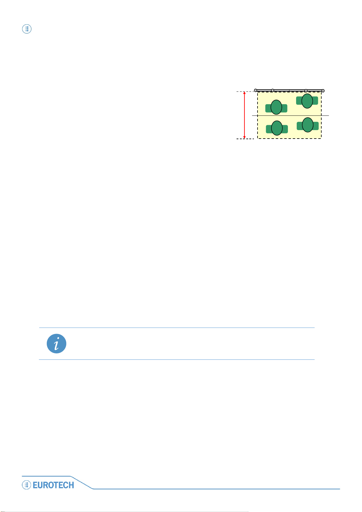
• The PCN-1001 can’t track more than 10
people at a time. In particularly crowded
conditions, i.e. on-board buses, 10 people
can be compressed in less than 1 m
detection area should be smaller. In these
2
, so the
70~90 cm
conditions a depth of 70~90 cm at floor level
is fine to guarantee a good tracking of
people.
Follow these steps to save the background:
1. Connect the PCN-1001 by pressing the “Connect” button
2. Select “8bit Disp. + median + FPN + ODC” in the drop-down list. In this way Windows 1 and 2 will display the
separated images as seen by the two cameras, subtracting the Fixed Pattern Noise (FPN) and the Optical
Distortion Correction (ODC). Window 3 will display the disparity map and a median filter will be applied for
reducing noise
3. Press the “►” button.
4. Ensure the doors of the gate are open!
5. Check that the PCN-1001 is correctly set up!
This means that in windows 1 and 2 you must see the scene as captured by the two cameras while in
window 3 the image has to be completely black or dark grey-scaled.
If for any reason it does not appear dark or any white spot appears, this will be recognised as one or
more objects present in the detection area. A background stored in these conditions may reduce
counting accuracy during the tracking process. Refer to the “Pay attention to the following issues:”
paragraph above for possible solutions
6. Press the “■” button
7. Select the “Controls” tab and click the “Scene Background” button. Ensure that window 3 remains
completely dark or dark grey-scaled until the process has completed. If not restart from step “5”
Wait for the progress bar to complete. When completed, the “Scene background Saved!” dialog box will be displayed.
NOTE:
Pay careful attention that the USB cable or any part of your body, especially feet, are not visible in the
detection area
44
PCN-
Page 45

Step 5: Use WinClient to test the tracking of people PCN-1001 User manual
PCN
1 2 3
Step 5: Use WinClient to test the tracking of people
The “tracking” process consists of a 3D image displayed in window 3 that is the differences between the images
from the left and right cameras.
The image in window 3 is also called “Disparity map”. As objects become closer to the cameras they will appear
lighter in colour.
To verify the tracking process:
1. Select “Tracking” in the drop-down list
2. Click the “►” button
3. Check if the images in window 3 are correctly displayed when somebody is enters into the detection area.
Figure 2. The tracking process
When the WinClient is closed, the system will continue counting according to the user’s configuration.
NOTE:
When closing the WinClient you MUST first Disconnect using the Disconnect button in the Connection Tab
-1001_UserMan_En_4.0
45
Page 46

Step 5: Use WinClient to test the tracking of people PCN-1001 User manual
1001_UserMan_En_4.0
Door threshold
Outside
Inside
In 1
Out 0
In 1
Out 1
Normal view
Disparity map
Counters
In 0
Out 0
In 0
Out 0
In 1
Out 0
Remember:
Example of counting
During the tracking
process, the two
counters are
incremented only if a
person enters the
detection area,
crosses the door
threshold and then
exits from the
detection area on the
opposite side.
46
PCN-
Page 47

Step 5: Use WinClient to test the tracking of people PCN-1001 User manual
PCN
WARNING!
disable it after the door is closed completely.
People counted as IN
People counted as OUT
Door threshold line
Door threshold line
How the threshold works when using digital inputs
NOTE:
Refer to ‘Notes about the Digital I/O interface’ on page
inputs.
When the counting process is disabled (i.e. when the door is closed), people remaining anywhere in the detection
area will be counted as IN, and the counter will be amended accordingly.
When the counting process is enabled (when the door is open), every person already within the door threshold
line and the portion of detection area facing the door, will be counted as OUT if they leave the detection area;
again, the counter will be amended accordingly.
69 for further information about the digital
The commutation time of digital inputs is extremely important because any propagation delay in the
signal may affect severely the precision of the counting.
The digital inputs should enable the PCN-1001 as soon as the door starts opening and should
-1001_UserMan_En_4.0
47
Page 48

(This page has been intentionally left blank)
Page 49

Part 3 – The PCN-1001 software PCN-1001 User manual
PCN
PART 3 – THE PCN-1001 SOFTWARE
-1001_UserMan_En_4.0
49
Page 50

(This page has been intentionally left blank)
Page 51

Install/update the software PCN-1001 User manual
PCN
WARNING!
VERSIONS OF EITHER THE “PCN-1001-DEMO-WIN32” OR “IMGSERVER” ARE USED TOGETHER.
Install/update the software
The software to use with the PCN-1001 is contained on the CD-ROM that comes with the development kit of the
PCN-1001 (the DTK-1001-00).
For the latest software releases, please refer to www.eurotech.com/en/download/PCN-1001
The main software packages to be used with your PCN-1001 are:
• pcn-1001-Imgserver
• pcn-1001-demo-win32
The pcn-1001-Imgserver
“Imgserver” is a daemon program that runs on the PCN-1001, it starts at boot time and performs the people
counting tasks. It accepts remote connections using both the RS485 and USB ports.
The PCN-1001 comes with Imgserver ready installed and ready to work.
A copy of this program is also contained in the CD-ROM.
.
The pcn-1001-demo-win32
“pcn-1001-demo-win32” is a package (supported by Windows XP, Vista, and 7) that, when run on the Host PC,
installs both the “WinClient” and the “RS485_GUI” programs:
The WinClient
“WinClient” is a Graphical User Interface (GUI) that allows you to configure/debug the PCN-1001.
The WinClient software has been created to access and configure one PCN-1001 at a time.
The RS485_GUI
“RS485_GUI” is a program that can be used to simulate real working conditions where the Host PC or the
Control Unit (the main on-board computer, for example a Eurotech DuraCOR system) sends/receives commands
via an RS485 connection to/from one or more PCN-1001.
IT IS IMPORTANT TO NOTE THAT THE SAME VERSION OF “PCN-1001-DEMO-WIN32” AND
“IMGSERVER” MUST BE INSTALLED RESPECTIVELY ON THE HOST PC AND ON THE PCN-1001.
INCOMPATIBILITIES WILL OCCUR AND THESE WILL CAUSE PROBLEMS IF OLDER AND NEWER
-1001_UserMan_En_4.0
51
Page 52

Install/update the software PCN-1001 User manual
1001_UserMan_En_4.0
Install/update the software on the Host PC
Before starting, save and unzip both the “pcn-1001-Imgserver” and the “pcn-1001-demo-win32” packages on
your Host PC into a specific folder (i.e. name it “Eurotech PCN-1001”).
Install / Update WinClient and RS485_GUI on the PCN-1001
WARNING!
Installing, uninstalling, or updating the WinClient on the Host PC will also cause the automatic
installation, uninstallation, or update of RS485_GUI.
1. If present, uninstall any previous versions of the WinClient and RS485_GUI before installing the new one
2. Navigate to the pcn-1001-demo-win32 folder. Double-click the “setup.exe” icon
52
PCN-
Page 53

Install/update the software PCN-1001 User manual
PCN
3. The InstallShield Wizard will guide you through the following installing/updating procedures:
• NEW INSTALLATION:
If you are installing the “WinClient” and "RS485_GUI" on the Host PC for the first time, you will obtain
the following messages:
• UPDATE:
If the “WinClient” and "RS485_GUI" are already installed on the Host PC, you will obtain the following
messages that allow you to modify, repair or remove them from the Host PC:
4. Follow the instructions that will appear
5. When completed click “Finish”
6. The new versions of WinClient and RS485_GUI programs have now been installed on the Host PC. The
related shortcuts icons will appear on the desktop.
-1001_UserMan_En_4.0
53
Page 54

Install/update the software PCN-1001 User manual
1001_UserMan_En_4.0
A
B
C D E
G
F
E
Updating Imgserver on the PCN-1001
The PCN-1001 comes with Imgserver already installed and ready to work.
When available, new versions of the Imgserver can be installed in the following way:
1. The PCN-1001 has to be turned on and connected to the Host PC via USB. Refer to “Install a PCN-1001” 33
and “Step 3: Configure the network between PCN-1001 and Host PC” on page 36 for further information
2. Start WinClient
3. Select the "Connection" tab (A) and click the “Scan” button (B).
Select the address of the required PCN-1001(C). Click the “Connect” button (D).
When connected, the Imgserver version will be displayed on the bottom line (the Status bar; E)
4. Select the "Controls" tab (F) and click the "System Update" button (G)
54
PCN-
Page 55

Install/update the software PCN-1001 User manual
PCN
5. A dialog box will appear.
Open the folder with the latest Imgserver file. Select the Imgserver file. Click “Open”
6. The Imgserver will be updated on the PCN-1001.
When done the following confirmation message will appear:
Click “OK”
-1001_UserMan_En_4.0
55
Page 56

Install/update the software PCN-1001 User manual
1001_UserMan_En_4.0
I
H
7. Select the "Connection" tab (H) and click the “Disconnect” button (I)
8. Close the WinClient program
9. IMPORTANT! Disconnect power to the PCN-1001 (turn it off)
10. Reapply power to the PCN-1001 (turn it on). Allow sufficient time for the system to start. A message like the
following will appear when the PCN-1001 has successfully rebooted and reconnected:
11. Restart the WinClient program
12. Reconnect (as done at steps 3 and 4).
13. Verify that the Imgserver has been updated by looking at the versions in the status bar
Note:
Refer to the download area of www.eurotech.com
to download the most updated software version.
56
PCN-
Page 57

Know WinClient PCN-1001 User manual
PCN
1 & 2
3
Window displaying the tracking process and the disparity map
4
Incoming counter
5
Outgoing counter
6
Drop-down list
7
8
“Connection” tab
9
“Controls” tab
10
“I/O Settings” tab
11
“Wide-Gate” tab
12
13
Status bar
11
9 8 10
12 6 5
13 7 4 3 2
1
Know WinClient
After you have properly connected and configured both the Host PC and the PCN-1001 as described above, if
you click the WinClient shortcut on the Desktop you will obtain the WinClient graphical interface:
Window displaying the left and right images acquired from the individual cameras
PCN Configuration Files Management
“Advanced” tabs 1/2 and 2/2
-1001_UserMan_En_4.0
57
Page 58

Know WinClient PCN-1001 User manual
1001_UserMan_En_4.0
• 8bit + FPN correction
Windows 1 and 2 will display the separated images as seen by the two
Windows 1 and 2 will display the separated images as seen by the two
Windows 1 and 2 will display the separated images as seen by the two
and trace their movement
The drop-down list
The drop-down list offers a choice of visualization modalities for the windows 1, 2 and 3:
cameras, subtracting the Fixed Pattern Noise (FPN)
• 8bit + FPN and ODC correction
• 8bit Disp. + FPN + ODC
• 8bit Disp. + median + FPN + ODC
• Tracking
Windows 1 and 2 will display the separated images as seen by the two
cameras, subtracting the Fixed Pattern Noise (FPN) and the Optical
Distortion Correction (ODC)
cameras, subtracting the Fixed Pattern Noise (FPN) and the Optical
Distortion Correction (ODC).
Window 3 will display the disparity map
cameras, subtracting the Fixed Pattern Noise (FPN) and the Optical
Distortion Correction (ODC).
Window 3 will display the disparity map and a median filter will be applied
for reducing noise
This is the only modality that activates the counting. Window 3 will display
the disparity map and a median filter will be applied for noise reduction.
Furthermore some white crosses will appear to indicate the detected people
The Start and Stop buttons
The Start (“►”) and Stop (“■”) buttons allow you to respectively start and stop the counting process.
PCN Configuration Files management (PCF)
This feature is useful when you have several PCN-1001 devices that have to be installed and all will have the
same operating conditions (i.e. same door on different buses of the same type).
It allows you to save the current configuration and load it to other PCN-1001 devices without setting each PCN1001 individually.
Note:
The PCN-1001 configuration that is going to be saved will contain all the setup parameters except for the
“RS485 Setup ID” and “Scene Background”.
How to save a PCF
1. Make sure that the PCN-1001 is not running (click the “■” button)
2. Click the “Save PCF” button
58
PCN-
Page 59

Know WinClient PCN-1001 User manual
PCN
Value
Description
FPS:
Frames Per Second. The number of images displayed by WinClient every each second.
Kernel v.
The Linux kernel version
System v.
The Operating system version.
Firmware v.
The FPGA firmware version.
Imgserver v.
The Imgserver program version.
3. A dialog box like the following will appear:
4. Save the current configuration with a file name (i.e. Config1)
How to load a PCF
1. Make sure that the PCN-1001 is not running (click the “■” button)
2. Click the “Load PCF” button
3. A dialog box like the following will appear:
4. Select the proper file name (i.e. Config1) and click “Open”
NOTE:
The “Scene Background” must be retaken for each new PCN-1001, even if the background is theoretically
the same
The status bar
When the PCN-1001 is working, the status bar displays the following information:
-1001_UserMan_En_4.0
59
Page 60

Know WinClient PCN-1001 User manual
1001_UserMan_En_4.0
Notes about images acquisition and FPS
During normal operations (default mode), the PCN-1001 acquires the images at a constant rate of approximately
60 Frames Per Second (FPS).
During configuration, the acquired images are transmitted to the Host PC for visualization. Depending on the Host
PCs characteristics and the USB connection, the FPS rate may differ. The value displayed in the bottom left
corner of the WinClient GUI is the current FPS rate detected by the Host PC. However the real FPS of the PCN1001 is not affected by these external factors and remains at 60 FPS.
The tabs
Figure 3. Connection, Controls and I/O Settings tabs
Figure 4. Wide-Gate and Advanced tabs
60
PCN-
Page 61

Know WinClient PCN-1001 User manual
PCN
The “Controls” tab
The “Controls” tab allows you to change the main settings of the PCN-1001 in order to obtain a good resolution
on windows 1, 2 & 3.
Any modifications to the settings will be automatically saved to the internal flash memory of the PCN-1001 and
takes immediately effect (a reset is not needed).
The “Date and Time settings” panel
Displays and allows you to set the system time and date.
Set date and time correctly!
This is extremely important especially in stand-alone installations where the user download periodically data via
USB using the “Save Records” feature.
The values displayed are updated when the system is connected. If after a successful connection the time and/or
date are not displayed correctly, enter the Regional Options within the Windows Control panel and set the time
separator to “.” And the date separator to “/”; after doing so reconnect to the PCN-1001 and verify that the time
and date are correctly displayed.
If the PCN-1001 remains without power for more than seven days, the current time and date information will be
lost, and therefore will need to be corrected.
The “Distance Configuration” panel
Allows you to set the distance between the PCN-1001 and the upper border of the detection area.
Example:
If the installation height is 230 cm above the floor and you want to count people high between one
and two meters, you have to select the radio-button “25-30 cm”.
The “Light intensity” panel
The light intensity of LED indicators can be adjusted automatically or manually by the using this slider and
Checkbox.
Flagging the checkbox will make the PCN-1001 automatically adjust the LED intensity according to the
environmental lighting conditions.
-1001_UserMan_En_4.0
61
Page 62

Know WinClient PCN-1001 User manual
1001_UserMan_En_4.0
Threshold
For installations within buildings:
In these kinds of installation, it is assumed that the environment has a constant illumination.
The right light intensity has to be found experimentally.
For on-board installations:
Slide the bar completely to the right, and put the light intensity to the maximum.
This will increase the counting accuracy even in installations where the environmental lighting conditions are
always changing and can vary suddenly.
The “In/Out direction” panel
Be careful to set the direction for incoming and outgoing people in the right way, paying attention that the arrows
refer to the motion of people as displayed on the WinClient interface.
Changing the direction will reset the in/out counters.
The “Door kind” panel
When, on-board a transportation vehicle, a door is dedicated to the entering only or the exiting only of
passengers, this option allows the explicit declaration of the kind of door.
This declaration does not disable the income counting in a door declared as “one-way out” but decrease the
erroneous counting of incoming people due to reflections or due to atypical behaviour of passengers (a
passenger that was intended to go out, invert his direction and returns back) in the proximity of the open door.
The “Door threshold” panel
This is an important parameter that has to be properly set to obtain a reliable counting process.
During the tracking process, the two counters are incremented only if a person enters the detection area, crosses
the door threshold and then exits from the detection area on the opposite side.
By default, the threshold is placed at row 60 (the image height is 120 rows). The position of the threshold line can
be set between row 30 and row 89.
In each visualization mode, except for “Tracking”, flagging the “View Threshold” checkbox will display the current
threshold (a white horizontal line) in Windows 1 and 2.
62
PCN-
Page 63

Know WinClient PCN-1001 User manual
PCN
Guidelines to find the best threshold position:
• Place it in a way that any person entering or exiting have to cross it.
• Place it away from high reflective surfaces (i.e. the steps on a bus/train). If the detection area includes
also a portion outside the transportation vehicle, the door threshold should not be set outside.
• Place it away from door-opening mechanisms
• It should be placed in the middle of the detection area, which if the PCN-1001 has been installed
correctly above the door, should correspond to a central position of the “Door threshold” slide bar
If a door is intended to be used in a single direction, for example “in only” or “out only”, it may be useful to
move the threshold towards the exit edge of the detection area.
The “Data records” panel
The Incoming & Outgoing counters along with Time & Date information is saved immediately by the PCN-1001;
every sixty seconds these values are appended to a text log file within the flash memory of PCN-1001.
Depending on the Optocoupled I/O functions selected (see the ‘Optocoupled I/O functions panel’ paragraph on
page 67) the information written to the log file will be different.
The following paragraphs describe the available log file formats.
The log file
The log file is a series of text lines. There are four different types of line:
Boot: The following line is added each time the PCN-1001 completes a boot cycle:
Boot date1 time2 Counter In3 Counter Out4
Count: The following line is added each time the counter registers a person as entering or leaving
Count date time Counter In Counter Out
Start: The following line is added when the Digital I/O has been enabled or the RS485 command “enable_pc 1” is
used
Start date time Counter In Counter Out
Stop: The following line is added when the Digital I/O has been disabled or the RS485 command “enable_pc 0”
is used
Stop date time Result In5 Result Out6
1
The date in dd/mm/yyyy format
2
The time in hh/mm/ss
3
Quantity of incoming people
4
Quantity of outgoing people
5
Quantity of people added to the Counter In since the last Start command
6
Quantity of people added to the Counter Status Out since the last Start command
-1001_UserMan_En_4.0
63
Page 64

Know WinClient PCN-1001 User manual
1001_UserMan_En_4.0
Counter In
Counter Out
Date
Time
Action
All the values in a text line are separated by a tab. This makes easy to export data into any spread-sheet
application (e.g.: Microsoft Excel, OpenOffice, etc.).
Example
The following is an example of log file from a bus with a single door:
Boot 26/09/2011 08:51:10 000000 000000
Start 26/09/2011 08:51:20 000000 000000
Count 26/09/2011 08:56:37 000001 000000
Count 26/09/2011 08:57:08 000002 000000
Count 26/09/2011 08:59:00 000002 000001
Count 26/09/2011 08:59:10 000002 000002
Stop 26/09/2011 08:59:20 000002 000002
Boot 26/09/2011 09:10:00 000002 000002
In this example:
At 08:51:10 the PCN-1001 was powered on, the current counter values were:
0 In, and 0 Out
At 08:51:20 the door was opened
At 08:56:37 1 person entered
At 08:57:08 1 person entered
At 08:59:00 1 person exited
At 08:59:10 1 person exited
At 08:59:20 the door was closed, the values showed that 2 people had entered and 2
people had exited
At 09:10:00 the PCN-1001 was powered on (for example a reboot occurred)
64
PCN-
Page 65

Know WinClient PCN-1001 User manual
PCN
NOTE:
If the background has altered
Saving the records of the log file
By clicking the “Save records” button you will be able to download the log file as text. You will be given the option
to “Save As” – “filename.txt”.
The PCN-1001 can record a maximum of 300,000 log lines.
When the PCN-1001 exceed the amount of 299,999 log lines the internal software will overwrite the oldest
block of 30,000 lines with the new data, leaving the remaining 30,000 x 9 lines already recorded.
In this case the system will continue to cancel and rewrite each successive block of 30,000 lines
It is possible to use the Mini USB 1.1 client connector located on the front side of the PCN-1001 in order to
transfer data (i.e. to a Host PC).
The “Scene background” button
This is an important parameter that has to be properly set to obtain a reliable counting process.
The acquisition and storage of the background is a fundamental and sensitive issue.
A bad background acquisition can affect seriously the counting process.
IMPORTANT NOTE:
Acquire the background in the following circumstances:
• Once the PCN-1001 has been installed
• When the PCN-1001 has been relocated
•
Pay attention to the following issues:
• The background has to be taken with no foreign removable objects in the detection area
• The background has to be taken with doors open, especially if the doors would block the PCN-1001s’
field of view as frequently occurs within buses or trains
• Lighting of the detection area should be diffused as much as possible. No spot lighting (e.g. solar
reflections or strong lighting) should be present in the detection area during background acquisition
• Highly reflective, geometric structures situated on or near the floor, such as the metallic parts for door
mechanisms, which cause extreme patterns of light and darkness when illuminated by strong light (e.g.
direct sunlight or directional halogen lighting) could lead to flawed distance measurements. To avoid
performance degradation due to these effects the structures and any high reflective surface should be
avoided as much as possible in the detection area
• Metallic or shiny objects (such as handles, bars, glass, etc.) should not cover a significant part of the
detection area. If this is not avoidable, the reflectivity of these items should be reduced by means of
non-reflective materials or modifying the “No Tracking Zone”.
Follow these steps to save the background:
1. Connect the PCN-1001 by pressing the “Connect” button
2. Select “8bit Disp. + median + FPN + ODC” in the drop-down list. In this way Windows 1 and 2 will display the
separated images as seen by the two cameras, subtracting the Fixed Pattern Noise (FPN) and the Optical
Distortion Correction (ODC). Window 3 will display the disparity map and a median filter will be applied for
reducing noise
3. Ensure the doors of the gate are open!
-1001_UserMan_En_4.0
65
Page 66

Know WinClient PCN-1001 User manual
1001_UserMan_En_4.0
NOTE:
going to the Start Menu > Settings > Control Panels > Display > Settings.
4. Check that the PCN-1001 is correctly set up!
This means that in windows 1 and 2 you must see the scene as captured by the two cameras while in
window 3 the image has to be completely black or dark grey-scaled.
If for any reason it does not appear dark or any white spot appears, this will be recognised as one or
more objects present in the detection area. A background stored in these conditions will cause a
wrong count during the tracking process. Refer to the “Pay attention to the following issues:”
paragraph above for possible solutions
5. Press the “►” button. Press the “■” button
6. Select the “Controls” tab and click the “Scene Background” button. Ensure that window 3 remains
completely dark or dark grey-scaled until the process has completed. If not restart from step “5”
7. Wait for the progress bar to complete. When completed, the “Scene background Saved!” dialog box is
displayed. The PCN-1001 is now ready to operate
If the PCN-1001 is correctly connected via USB to the Host PC and the drivers is correctly installed but you
still cannot see the images in windows 1 and 2, try to set the Host PC colour depth to 16 bit (or less) by
The “Reset counters” button
Zero’s the Incoming and Outgoing counters.
The “Restore Factory Settings” button
Resets the system to its original factory configuration.
The “System update” button
Use this button to upgrade the PCN-1001 software when a new version becomes available.
You will find copies of the software on the CD-ROM provided with your PCN-1001.
You should also check the Download area on the Eurotech website for the latest updates.
66
PCN-
Page 67

Know WinClient PCN-1001 User manual
PCN
The system ignores any signals received on the input lines
• Test:
Allows the operator to test the two input lines (See ‘Optocoupled I/O test panel’ on next
Sets the incoming and outgoing counters to zero when a rising edge is detected. In the
When the GPI1 / GPI2 inputs receive a rising edge (they are enabled) the PCN-1001 will
The “I/O Settings” tab
The PCN-1001 can be interfaced and triggered by means of 2 independent optocoupled inputs and 2
independent optocoupled outputs.
The RS485 port is the main communications interface used when the PCN-1001 is installed on-board a
transportation vehicle.
Each modification to these settings will be automatically saved in the internal flash memory of the PCN-1001 and
takes immediate effect (a reset is not needed).
The “Optocoupled I/O functions” panel
The two inputs, GPI1 and GPI2 (GPI means General Purpose Input), can be used in four different modes.
These can be selected using the two drop-down menus.
Press the “Set” button to confirm the drop-down menu selection
• Do nothing:
page for more details)
• Reset counters:
• Enable/Disable
counting
Wide-Gate configuration only the GPI2 can be set as reset. It has to be set connecting the
first PCN-1001 and the signal will be available on the last PCN-1001
start the counting process.
When the GPI1 / GPI2 inputs receive a falling edge (they are disabled) the PCN-1001 will
stop the counting process.
In the Wide-Gate configuration only the GPI1 can be set as Enable/Disable.
The default mode for the PCN-1001 when powered-up is “Counting Enabled”.
The counting will be Disabled / Enabled only when the GPI changes state.
Example 1:
a) The PCN-1001 is powered up: the counting will be enabled by default
b) The GPI is enabled: the counting was already enabled at power up and nothing change
c) The GPI is disabled: the counting will be disabled
Example 2:
a) The PCN-1001 is powered up: the counting will be enabled by default
b) The GPI is disabled: the counting will be disabled
c) The GPI is enabled: the counting will be enabled
-1001_UserMan_En_4.0
67
Page 68

Know WinClient PCN-1001 User manual
1001_UserMan_En_4.0
The “Optocoupled I/O test” panel
The two outputs, GPO1 and GPO2, (GPO means General Purpose Output) have the purpose to react when a
person is counted:
• GPO1: By default is associated to incoming people
• GPO2: By default is associated to outgoing people
The optocoupled output electronics behave as low-side switches normally closed.
When the PCN-1001 detects a person, one of the two outputs (depending on the direction of the person) turns its
status to open for a period of “GPO-Open-Time” milliseconds.
The GPO-Open-Time (GPOOT) can be configured inserting a value (from 8 to 1020 milliseconds) in the two
GPO1 and GPO2 open time fields on the “Optocoupled I/O test” panels.
If two people walk in the same direction under the PCN-1001, the first signal will be immediately sent to the
appropriate output, the second will be queued for (2 x GPOOT) milliseconds.
In the Wide-Gate configuration the GPO1 used will be the one of the first PCN-1001.
The GPO2 will be the one of the last PCN-1001. In any case, both the GPO-Open-Times have to be set
connecting the first PCN-1001.
GPI1 Test / GPI2 Test
Follow these steps to test the inputs:
1. In the drop-down lists of the “Optocoupled I/O functions” panel select the option “Test” for either GPI1 or
GPI2
2. Press the “Set” button
3. Press either “GPI1 Test” or “GPI2 Test” button. If a rising edge is received on GPI1 or GPI2, the
corresponding grey rectangle will turn to white. If a falling edge is received it will turn to grey
NOTE:
The “Test” functions are only available via Socket API, not via RS485.
GPO1 Test / GPO2 Test
In order to test the outputs press the “GPO1 Test” or “GPO2 Test” button. The GPOOT value will be set to the
nearest multiple of four lower than or equal to the inserted value.
NOTE:
The “Test” functions are only available via Socket API, not via RS485.
68
PCN-
Page 69

Know WinClient PCN-1001 User manual
PCN
PARAMETERS
SYMBOL
VAL UE
UNIT
Maximum Voltage
Maximum Reverse Voltage
V
REV MAX
32
V
Maximum Current
I
MAX
300
mA
Maximum Current on Digital OUT V+
I
MAX ON V+
20
mA
2nd
PCN-1001
1st
PCN-1001
M2M2 M1M1
60 cm
Direct
connection
Vehicle Data BUS (Communication interface and power supply)
Central
Unit
Door
Notes about the Digital I/O interface
The PCN-1001 can be interfaced and triggered by means of two general-purpose inputs and two general-purpose
outputs. For example, the general-purpose digital I/O interface can be used to detect a doors status (open or
closed).
In this case the logic to follow is:
0 Door closed
1 Door open
The counters will be activated when the door
status becomes 1 (Open).
The general-purpose I/Os are 1 kV isolated
and are available on the M1 connector.
They allow for a direct connection to industrial equipment with an isolation of 3750 V
In the Wide-gate configuration the door status input has to be connected to the M1 connector of the first PCN-
1001, using GPI1. For further information refer to the ‘Optocoupled I/O functions panel’ paragraph on page 67
and to the Note: ‘How the threshold works when using digital inputs’ on page 47.
The Output Block
The figure below shows the electrical schematics of the output block. The labels on the right side refer to the M1
and M2 connectors, while the left side of the picture refers to the internal processing part of the system.
The Output Block behaves as a low-side switch. The load connected to the low-side switch can draw current
either from an external power source or from the Digital OUT V+ referred to the Digital OUT GND.
RMS
.
Recommended output operating conditions
-1001_UserMan_En_4.0
Figure 5. Schematics of the output differential optocoupled block
V
32 V
MAX
69
Page 70

Know WinClient PCN-1001 User manual
1001_UserMan_En_4.0
PARAMETERS
SYMBOL
VAL UE
UNIT
Minimum Threshold Voltage
V
THR MIN
2.4
V
Maximum Voltage
V
MAX
32
V
Maximum Reverse Voltage
V
REV MAX
32
V
Typical Current
I
3.6
mA
The Input Block
The figure below shows the electrical schematics of the input differential optocoupled block. The “Digital IN”
labels on the left side refer to the digital IN signals on the M1 and M2 connectors, while the right side of the figure
refer to the internal processing part of the system. This input block can be connected to a standard TTL port. The
Input Block draws a constant current when driven above the threshold.
Figure 6. Electrical schematics of the input differential optocoupled block
Recommended input operating conditions:
TYP
Note: How to simulate a digital input
Make the connections displayed in the following figure. The switch simulates the digital input.
For development purposes a digital input can be simulated using Cn5 of the CBL-1001-00 cable kit (see page
100) and an ON/OFF switch.
The “RS485 Setup” panel
See ‘Configure the RS485 port of the PCN-1001’ paragraph on page 82 for further information.
70
PCN-
Page 71

Know WinClient PCN-1001 User manual
PCN
The “Wide-Gate” tab
When you need to monitor gates wider than 120 cm the “Wide-Gate” is an algorithm that has been developed in
order to properly configure the necessary PCN-1001 devices.
Setting up the PCN-1001 devices for the Wide-Gate configuration
1. Connect properly all the PCN-1001 devices as described in the paragraph Number of PCN-1001 devices
required on page 27
2. Connect your Host PC via the USB port (located under the service plate) to the Master PCN-1001 (the one
directly connected to the Control Unit)
a. Launch the WinClient utility and Click “Scan”
b. Select the IP address of the PCN-1001. Click “Connect”
c. Select the “Controls” Tab. Click “Restore Factory Settings”
d. Click “Yes” when the “Warning” message will appear.
If you do not perform a restore before configuring the “Wide-gate” mode you may receive the
following error:
e. Select the “Connection” Tab and click “Disconnect”
st
3. Connect your Host PC via the USB port to the 1
Slave PCN-1001
a. Click “Scan”
b. Select the IP address of the PCN-1001 and click “Connect”
c. Select the “Controls” Tab
d. Click “Restore Factory Settings”
e. Click “Yes” when the “Warning” message will appear
f. Select the “Connection” Tab and click “Disconnect”
4. Move to next Slave PCN-1001 and repeat the above step 3 for all Slaves
5. Connect your Host PC via the USB port to the Master PCN-1001
a. Click “Scan”
b. Select the IP address of the PCN-1001 and click “Connect”
c. Select the “Wide-Gate” Tab
d. Insert the quantity of counters connected (i.e.: 2)
-1001_UserMan_En_4.0
71
Page 72

Know WinClient PCN-1001 User manual
1001_UserMan_En_4.0
Note:
to the slave counters.
e. Set the installation height (from the floor) of the counters
f. Click “Enable Wide-Gate”:
- If problems occur you will obtain a Wide-Gate Error. Check for the cable connections (you
may have selected a higher system number than actually connected/available)
- If all is ok a confirmation message will appear. Click “OK”
g. Select the “Controls” Tab
h. Click “Scene Background”
i. Click “OK” when a confirmation message will appear
j. Select the “Connection” Tab and click “Disconnect”
6. Cycle the power on all the PCN-1001 devices
7. Wait for the PCN-1001 devices to boot
8. The PCN-1001-00 is now ready for normal “Wide-Gate” counting operations
72
Remember to set the configuration parameters (direction, door threshold, light intensity, etc.).
The configuration parameters have to be set only after the Wide-Gate mode has been enabled
and you are connected to the Master PCN-1001. This will redirect the configuration parameters
PCN-
Page 73

Know WinClient PCN-1001 User manual
PCN
120 pixels
0
119
End X
Start X
Start Y
End Y
Start Y
End Y
Detection area
160 pixels
Up Line
Down Line
0
159
The “Advanced (1/2)” tab
“No Tracking Zone” panel
NOTE: The no tracking zone feature is NOT available in Wide-Gate mode
The “No Tracking Zone” feature allows you to define rectangular zones in the detection area where tracking will
not be performed. This feature can be used to mask surfaces that are very reflective or with spot lighting.
RANGES:
End X = pixel 0 to 70
Start X = pixel 159 to 91
Start Y = pixel 0 to119
End Y = pixel 119 to 0
Up Line = pixel 0 to 59
Down Line = pixel 119 to 60
Example:
The picture below shows the Detection area with the no tracking zones represented as dashed areas:
The picture below shows how the Detection area will appear in the WinClient windows.
The no tracking zones are represented as dark grey rectangles:
-1001_UserMan_En_4.0
73
Page 74

Know WinClient PCN-1001 User manual
1001_UserMan_En_4.0
The picture below shows how the no tracking zones will affect the cameras’ field of view and the Detection area.
A person crossing the Detection area in a non-masked zone will be counted.
A person crossing the Detection area in a masked zone will not be counted.
74
PCN-
Page 75

Know WinClient PCN-1001 User manual
PCN
Suggested depth:
Pay attention to the following issues:
• Exclude as much as possible the area outside the transportation vehicle
• Verify that all the entrance area is detected properly. Make a person move under the PCN-1001s and
verify the correct detection
• The PCN-1001 can’t track more than 10
people at a time. In particularly crowded
conditions, i.e. on-board buses, 10 people
can
be compressed in less than 1 m
detection area should be smaller. In these
2
, so the
70~90 cm
conditions a depth of 70~90 cm at floor
level is fine to guarantee a good tracking of
people.
“Single Way Tracking” panel
If this option is flagged, tracking will only work when people passing under the Counter are moving in one
direction. Tracking will not work when people are moving in two directions at the same time.
“PCN-1001 System diagnostic” panel
Note:
With the WinClient software revision 2.2 the “PCN-1001 System diagnostic” works only if the PCN-1001 is
set in single configuration.
This is a diagnostic algorithm that detects and signals any problem that may occur to the optical section of the
PCN-1001 (i.e.: blind cameras, cameras malfunction, luminosity too low, etc.).
Pressing the “Get Status” button will change the colour of the grey circle:
• If the circle is red the diagnose is negative (there is a problem)
• If the circle is green the diagnose is positive (no problems occurred)
Every time the diagnostic status changes, it will be written on the log file
-1001_UserMan_En_4.0
75
Page 76

Know WinClient PCN-1001User manual
1001_UserMan_En_4.0
COMM AND
DESCRIPTION
diagnostic_en 1 (unsigned char)
Diagnostic enabled (default configuration)
diagnostic_en 0
Diagnostic disabled
pcn1001_status
Returns the diagnostic status displaying two values (unsigned char)
The second value indicates the error code (it is 0 if the diagnostic is positive)
COMM AND
DESCRIPTION
move_det_en 1 (unsigned char)
Move detection enabled
move_det_en 0 (unsigned char)
move_det_val
Returns the current value of the “Move detection” parameter.
The final value should be the average between the right and left sensors
value of the new threshold (int)
move_det_status
Returns the current move detection status displaying a value (unsigned
disabled or because there is a cross through the gate
The following commands can be used to manage the system diagnostic:
The first value will indicate the diagnose status:
• If it is 1 the diagnose is positive (no problems occurred)
• If it is 0 the diagnose is negative (there is a problem)
Note:
All the commands listed in the table above are also available for the RS485_GUI except for the
“pcn1001_status” command that returns the diagnose status without the error code.
“Use Move detection” panel
“Use Move detection” is an algorithm that when enabled enhances the detection sensitivity.
Note:
It is suggested that this feature is kept as enabled.
The colour of the grey circle will change in the following way:
• The circle should appear green when somebody is crossing the detection area
• The circle should appear red in other cases.
The following commands can be used to manage the Move Detection:
Move detection disabled
Two values (int) will be returned, one for the right sensor and one for the left
sensor.
move_det_thr Used to set the threshold value. Use the “Move_det_thr” followed by the
char) that can be:
0 if the counting is disabled
1 if the counting is enabled because the “move detection” algorithm is
76
PCN-
Page 77

Know WinClient PCN-1001 User manual
PCN
WARNING!
This will happen because the count is disabled during the background acquisition.
“Time Background” panel
The “Time Background” is an algorithm that can be used after the “Scene background” procedure. It allows you to
dynamically acquire the background in order to manage intense light variations of the detection area or manage
static objects that may be introduced in the detection area after its first acquisition during the installation, all
conditions that may affect the scene background.
The “Time Background” feature has been specifically developed for building installations.
If the PCN-1001 is installed on-board a transportation vehicle it is strongly recommended to disable
the Time background by setting to “0” the value of the “Time bkg” parameter.
This because the time when the door will be open is not predictable. If the acquisition of the
background starts while the door is opening there would be a discrete number of false negatives.
The value of the “Time bkg” parameter indicates how many minutes should pass before automatically executing a
new background acquisition; this happens only if during this period of time the image changed a number of pixels
higher than the valued indicated by the “Static Threshold” parameter. The maximum “Static Threshold” value is
19200 pixels.
NOTE:
The “Time Background” algorithm foresees that any person stands in the detection area for less than the
amount of time (in minutes) set by “Time bkg”
Typical values are:
• “Time bkg” = 2-5 minutes (Default set is 0 and means disabled)
• “Static Threshold” = 1500-3500 pixels (Default set is 2500)
The “Time Background” algorithm is enabled giving to “Time bkg” a value higher than 0.
Use the command “timebkg” followed by the number of minutes (unsigned char) in order to set “Time bkg”
Use the command “staticth” followed by the threshold value (number of pixels (int)) in order to set “Static
Threshold”.
-1001_UserMan_En_4.0
77
Page 78

Know WinClient PCN-1001 User manual
1001_UserMan_En_4.0
The “Advanced (2/2)” tab
“Stairs Upgrade” panel
Flag the “Stairs Upgrade Enable” feature if stairs are present inside the detection area.
This will improve the accuracy of counting.
Note:
It is suggested to keep this feature enabled.
78
PCN-
Page 79

Test an RS485 connection and use the RS485_GUI PCN-1001 User manual
PCN
Warning:
fail-safe bias for each data line/wire when the lines are not being driven by any device.
Test an RS485 connection and use the RS485_GUI
Introduction
Thanks to its RS485 ports, the PCN-1001 allows you to take advantage of all the benefits of an RS485 network,
including the possibility of connecting multiple devices – up to 32 at the same time – and perform
communications over long distances even in electrically noisy environments.
RS485 communications are based on a master/slave configuration:
• The master (a Host PC such as a laptop or, in a real situation, the main on-board computer that acts as
the Control Unit, for example a Eurotech DuraCOR system) begins communications by sending a
message to the slave devices
• The slave devices (the PCN-1001 devices) analyse the message, execute a command (if required) and
transmit the answer to the master.
The “RS485_GUI” is a program that, once installed on the Host PC, can be used to simulate a real RS485
connection.
Warning:
The parameters of the serial port on the Host PC and PCN-1001 must be equal (see ‘Configuring the RS485
port of the PCN-1001’ on page 82)
The PCN-1001 system does not include any line termination resistor, nor any fail safe bias resistors.
The two ends of the RS485 bus should include a termination resistor connected across the Data + and Data
– wires. Furthermore, one end of the RS485 bus should include pull-up or pull-down resistors to ensure a
-1001_UserMan_En_4.0
79
Page 80

Test an RS485 connection and use the RS485_GUI PCN-1001 User manual
1001_UserMan_En_4.0
Notes:
o http://www.ftdichip.com/Drivers/VCP.htm
Notes about the RS485 serial bus for development purposes
• The same “Multifunction cable” (found in the CBL-1001-00 Cable Kit) you are using to supply power to the
PCN-1001, also allows you to connect the PCN-1001 to the RS485 port of the Host PC by using Cn4.
• Personal Computers generally do not have a RS485 port. You can use the “703704001SL Adapter” (an
element of the CBL-1001-00 Cable Kit) to connect Cn4 of the Multifunction Cable with the USB port of the
Host PC. The 703704001SL Adapter also integrates one termination resistors (120 Ohm) and two fail safe
resistors (560 Ohm). Refer to “CBL-1001-00 cable kit” on page 100 before attempting to use the
703704001SL Adapter.
Figure 7. The “Multifunction Cable” Figure 8. The “703704001SL Adapter”
• The 703704001SL Adapter includes the 120 Ohm termination resistors and the 560 Ohm fail safe resistors
• The “CDM 2.06.00 WHQL Certified” software (available on the CD-ROM) has to be installed on the Host
PC before connecting the 703704001SL Adapter. Visit the following websites for further software
information and updates:
o http://www.ftdichip.com/Documents/InstallGuides.htm
80
PCN-
Page 81

Test an RS485 connection and use the RS485_GUI PCN-1001 User manual
PCN
Fail-safe resistor 562 Ω (*)
Fail-safe resistor 562 Ω (*)
Termination resi stor 133 Ω (*)
Example of RS485 network
Several PCN-1001 devices can be connected in a Multi-drop RS485 two-wire half-duplex setup, see the diagram
below. In this configuration:
• You need a Host PC that acts as Master device, manages the RS485 network, and has ID number = 1
• Each one of the PCN-1001 devices must have same values for Baud Rate, Data Bits, Parity and Stop Bits,
but different ID number, starting form 2.
The Host PC starts the communication and includes the address of the target PCN-1001 within the SNP (Small
Network Protocol, see the paragraph ‘The communication protocol’ on page 87).
All the PCN-1001 devices receive the command but only the target PCN-1001 will respond.
Note:
In Wide-Gate Configuration the Host PC sees only the first PCN-1001 of each group of counters in and the
address has to be assigned only to this one.
-1001_UserMan_En_4.0
81
Page 82

Test an RS485 connection and use the RS485_GUI PCN-1001 User manual
1001_UserMan_En_4.0
Configure the RS485 port of the PCN-1001
Use WinClient to configure the RS485 ports of the PCN-1001. Select the “I/O Settings” tab and refer to the
“RS485 Setup” panel as shown below:
Insert there the parameters of the PCN-1001 serial port and then click “Set” to save them.
Each modification to these settings will be automatically saved in the internal flash memory of the PCN-1001 and
takes immediate effect (a reset is not needed).
82
PCN-
Page 83

Test an RS485 connection and use the RS485_GUI PCN-1001 User manual
PCN
Start the RS485_GUI. Configure the RS485 port of the Host PC
Double click on the RS485_GUI link on the Host PC desktop. The following interface will appear:
It allows you to test all the commands available to the RS485 port.
Before starting communications, it is important to verify that the RS485 port configuration is correct.
These values are shown in the status bar of the GUI.
They can be modified selecting in the main menu: Settings > COM Settings.
The screenshot like the following will appear:
-1001_UserMan_En_4.0
Warning:
It is important that the Baud Rate, Data Bits, Parity and Stop Bits values have to be the same for the master
and for the slaves connected.
83
Page 84

Test an RS485 connection and use the RS485_GUI PCN-1001 User manual
1001_UserMan_En_4.0
RESPONSE
DESCRIPTION
[Slave #2] sled
The PCN-1001 has received the “sled” command followed by the LED level (see “RS485 Protocol”)
and replied with the string: “sled”.
Got corrupted reply!!!
The RS485_GUI could not understand the answer.
Timeout expired!!!
“Recipient” and “Polling” panels
The first operation to do is polling; this will verify the connection status of the intended target PCN-1001.
To do this, Insert the appropriate address in the Recipient box and then click the Start button.
If the appropriate PCN-1001 is found, the address is correct and the port is configured correctly, the software will
display a message like: “Got reply from [Slave #2]”.
Otherwise the following message will be displayed: “Timeout expired!!!” In this case, you must verify the settings
and try again.
For each command that has been sent to a PCN-1001, the RS485_GUI waits for an answer.
Three kinds of answer are available:
The signal has been lost and the RS485_GUI did not receive any answer.
Flag “Broadcast” for sending a message to all the PCN-1001 devices connected (i.e.: for setting the same time
and date to all the PCN-1001)
When a message is sent in broadcast mode, the PCN-1001 devices will not reply.
84
PCN-
Page 85

Test an RS485 connection and use the RS485_GUI PCN-1001 User manual
PCN
VAL UE
DESCRIPTION
Kernel version
PCN-1001 Linux kernel version.
System version
PCN-1001 operating system version.
Firmware version
PCN-1001 FPGA firmware version.
Imgserver version
Enable person counting
Enables the person counting process.
Disable person counting
Disables the person counting process.
Get counters
Requests the Incoming and Outgoing counter values.
Reset counters
Resets the Incoming and Outgoing counters.
Get Date Time
Enable Diagnostic Control
Enables the Diagnostic Control
Disable Diagnostic Control
Disables the Diagnostic Control
Get Diagnostic status
Returns the diagnostic status displaying:
Test Digital Input 0 & 1
Allows displaying in the log view a message about the state of the digital input 0 or 1.
“System Info” panel
The “System Info” combo box shows the software versions installed on the PCN-1001.
It also allows you to read and modify the counters status and disable the counter algorithm.
Select the value and press “Send”.
The Imgserver program version.
Resets the Date and the Time
1 if the diagnose is positive (no problems occurred)
0 if the diagnose is negative (there is a problem)
“IP Address” panel
This allows you to insert the PCN-1001 IP address.
The default IP address is 10.100.10.100; the first octet if fixed to avoid network configuration mismatch.
In Wide-Gate configuration all the PCN-1001 of same group will obtain the same IP address
“Date and Time settings” panel
This allows you to set the Time and Date on your PCN-1001.
“System Update” panel
The “System Update” button, like the equivalent button in “WinClient”, allows you to choose an Imgserver to be
sent to the PCN-1001 via RS485.
-1001_UserMan_En_4.0
85
Page 86

Test an RS485 connection and use the RS485_GUI PCN-1001 User manual
1001_UserMan_En_4.0
The file transfer progressing is displayed in the log view as shown as follows:
No other operation is allowed during file transfer.
When transfer finishes a proper message will be shown in the log view and the user will be allowed to perform
other operations.
The “Stop” button stops the transfer and interrupts the update.
Notice that even if during the file transfer some packets are lost the protocol guarantees a successful
transmission by sending again the lost packets. If more than 10 consecutive packets are lost the application will
stop the file transfer and an error message will be displayed in the log view.
“Optocoupled Inputs functions” panel
See the section ‘The I/O settings tab – Optocoupled I/O’ on page 67.
“Optocoupled outputs open time” panel
See the section ‘The I/O settings tab – Optocoupled I/O’ on page 67.
Light intensity
This allows you to set the LED intensity. See the section ‘The “Light intensity” panel’ on page 61.
“Log” panel
86
The “Save records” button allows you to download the log file as a text. This option works as ‘Save the records of
the log file’ on page 65.
The “Stop” button allows you to stop and cancel the saving process.
PCN-
Page 87

Test an RS485 connection and use the RS485_GUI PCN-1001 User manual
PCN
FIELD
LENGTH (BYTES)
CONTENTS
PreAmble
5
5 times 0xFF, to be sent prior to the initial character in order to give
time for change of transmission direction
StartCharacter
1
SOH = 0x01
Source
1
Destination
1
Address of recipient
TotalPacketNumber
1
Total number of packets
PacketNumber
1
Number of this packet
First packet has number 1
DataLength
2
Data
0 to MAX_DATA_LENGTH
Each byte can contain 0 to 0xFF
CRC16
2
CRC16 (x16 x15 x2 x0) check sum calculated from Source to Data
Postamble
1
0xFF.
The communication protocol
SNP (Small Network Protocol) is the communication protocol used in the RS485 connection.
The packet format contains the addresses of both the sender and recipient and the number of packets to be sent
along with the current packet number.
Bit stuffing is not used because, when the length of data field is stated, all values can be sent in the data field.
The maximum length of the data field is MAX_DATA_LENGTH = 1024 bytes.
Address of sender
States the length of the data field
LSB (Least Significant Byte) is to be sent first
(both fields included) with an initial value of -1.
LSB is to be sent first
Remember that there is only one master on the bus, while all others are slaves. When the master has sent a
message to a slave, an answer from the slave is expected. A slave cannot send anything to a master without
being asked. It is possible to send to all slaves at a time (broadcast), which means that slaves do not return an
answer and that messages are not retransmitted.
-1001_UserMan_En_4.0
87
Page 88

Test an RS485 connection and use the RS485_GUI PCN-1001 User manual
1001_UserMan_En_4.0
Receive Message
Send Message
Send Message
Master
“S”
Slave
“J”
Receive Message
Receive Message
Polling to Slave
Polling reply
Receive Message
Master
“S”
Slave
“J”
Polling
The master can poll a slave who answers with a message to the master. A poll is defined as a packet with:
TotalPacketNumber = 0
PacketNumber = 0
DataLength = 0
Scenarios
The following charts are intended to give an idea of how the sequences are sent/received by the master and
slave devices:
Short Message to Slave
Polling
[‘S’, ‘J’, 1, 1, x]
[‘J’, ‘S’, 1, 1, y]
[‘S’, ‘J’, 0, 0, 0]
[‘J’, ‘S’, 0, 0, 0]
88
PCN-
Page 89

Test an RS485 connection and use the RS485_GUI PCN-1001 User manual
PCN
Source
Destination
TotalPacketNumber
PacketNumber
DataLength
NAM E
LENGTH (BYTES)
CONTENTS
Command string
0-256 bytes
Command
String terminator
Value 1
1,2,4
First parameter
Value 2
1,2,4
Second parameter
….
1,2,4
….
Send Message
Received by all
Broadcast Message
Part 3
[‘S’, ‘J’, 3, 3, x]
Systems
Each message between Master and Slave is made in the following format:
Source: Address of the device transmitting the message
Destination: Address of the target device
TotalPacketNumber: Quantity of Packets to be sent
PacketNumber: The number of the current packet being sent
DataLength: Length of the data in this Packet [0x01 to 0xFE or MAX]
Therefore, as we can see from the examples on the previous pages, a message may take this form:
[0x01, 0x02, 3, 2, MAX]
In this case Node “0x01” is sending a message to Node “0x02”; this is package 2 of 3, and is MAX (255)
characters long. Whereas:
[0x02, 0x01, 1, 1, 2]
would be Node “0x02” is sending a message to Node “0x01”; this is package 1 of 1, and is 2 characters long.
The following message would be a Broadcast message:
[0xFF, 1, 1, 1, 2]
This is indicated by the 0xFF, which means all Slave devices will act upon the message, however, no reply will be
sent by any of the Slave devices.
The DATA field
All the messages exchanged between the Master and the Slave units have to be encapsulated in the SNP
transmission.
The command to send is contained in the Data field of the SNP protocol.
All the commands are formed by: the Command string, the String terminator, and some values (Value 1, Value 2,
…). Each value can be a number (1, 2 or 4 bytes long ) or a string.
The Data field maximum length is contained in the MAX_DATA_LENGTH
The Data field is formed by:
-1001_UserMan_En_4.0
1 0
89
Page 90

Test an RS485 connection and use the RS485_GUI PCN-1001 User manual
1001_UserMan_En_4.0
COMM AND
STRING TERMINATOR
ARGUMENT
Sled 0 100
SNP PACKAGE
VAL UE
Preamble
0xFF
Preamble
0xFF
Preamble
0xFF
Preamble
0xFF
Preamble
SOH
0x01
Source
0x01
Destination
0x02
TotalPacketNumber
0x01
PacketNumber
DataLength
0x06
0x00
Data
Command “sled”
0x73(s)
0x6C(l)
0x64(d)
String terminator
0x00
CRC16
CRC value = -27888
0x10
Postamble
0xFF
COMM AND
STRING TERMINATOR
COMM AND
STRING TERMINATOR
“ker_version”
0
COMM AND
STRING TERMINATOR
ARGUMENTS
“ker_version”
0
“2.1”
Example 1: setting the LED intensity to 100
In this case the Data is composed by the SLED command, the string terminator, and an argument (an unsigned
char parameter, 8 bits long):
The complete message is:
0xFF
0x01
0x65I
Argument (value = 100) 0x64
0x93
The slave will reply to this command with:
“sled” 0
Example 2: requesting the kernel version installed in the PCN-1001
Example of request
This command does not need any parameter.
The Slave will answer with:
In this case, the parameter in the answer of the slave will be a string containing the kernel version.
90
PCN-
Page 91

Test an RS485 connection and use the RS485_GUI PCN-1001 User manual
PCN
COMM AND
DESCRIPTION
address
Sets the PCN-1001 IP address
autoled
diagnostic_en
Enables or disables the diagnostic
enable_pc
Enables or disables the counting process
fw_version
Reads the version number of PCN-1001 FPGA firmware
gcounters
Returns the values of the Incoming and Outgoing counters
gdatetime
input0 / input1
Sets the functions of the two input lines
ker_version
Reads the version number of PCN-1001 kernel
output0/output1
Sets the optocoupled outputs open time
pcn1001_status
Returns the PCN-1001 diagnostic status
reset
sdatetime
Sets Date and Time information
sled
Sets the LED intensity
sys_version
Reads the version number of PCN-1001 operating system
version
Reads the version number of PCN-1001 core software
Command
address
Command Description
Sets the IP address of the PCN-1001
Parameters
String
Parameters Description
Returns
Command
autoled
Command Description
Enable the automatic regulation of the LEDs.
command) will be ignored.
Parameters
Unsigned char (1 byte)
Parameters Description
0: Disabled
Returns
Command
diagnostic_en
Command Description
Enables or disables the diagnostic
Parameters
Unsigned char (1 byte)
Parameters Description
Returns
Commands availability
These commands are incorporated in the SNP (Small Network Protocol) protocol.
Enable the automatic regulation of the LED indicators
Reads the date and the time
Resets the Incoming and Outgoing counters
address
autoled
diagnostic_en
String containing the IP address (e.g.: “10.100.10.100)
This regulation is based on the luminosity of acquired images
If the automatic regulation is activated the manual control (sled
1: Enabled
-1001_UserMan_En_4.0
0: Disabled
1: Enabled
91
Page 92

Test an RS485 connection and use the RS485_GUI PCN-1001 User manual
1001_UserMan_En_4.0
Command
enable_pc
Command Description
Parameters
Un unsigned char (1 byte)
Parameters Description
0: Disable
1: Enabled
Returns
Command
fw_version
Command Description
Returns the PCN-1001 firmware revision.
Parameters
Parameters Description
Returns
String containing the firmware revision number (e.g.: “1.8”)
Command
gcounters
Command Description
Returns the current counter values (In & Out)
Parameters
Parameters Description
Returns
Two unsigned values (4 bytes long).
Command
gdatetime
Command Description
Gets date and time in the PCN-1001
Parameters
Parameters Description
Returns
String containing the date and the time in PCN-1001
Command
input0 / input1
Command Description
Enable the functions for the two Optoisolated inputs.
“The I/O settings tab- Optocoupled I/O”.
Parameters
Parameters Description
0: Input disabled
2: Enable the function “Enable/Disable person counting”
Returns
enable_pc
Enables or disables the counting program
fw_version
gcounters
gdatetime
input0 / input1
1st is incoming counter value
nd
is outgoing counter value
2
The available functions are:
• Reset Counters
• Enable / Disable person counting.
For further information see the chapter:
Un unsigned short (2 bytes)
1: Enable the function “reset counters”
92
PCN-
Page 93

Test an RS485 connection and use the RS485_GUI PCN-1001 User manual
PCN
Command
ker_version
Command Description
Parameters
Parameters Description
Returns
String containing the Kernel version number (e.g.: “2.1”)
Command
output0 / output1
Command Description
Optocoupled I/O).
Parameters
Un unsigned short (2 bytes)
Parameters Description
8 and 1020
Returns
Command
pcn1001_status
Command Description
Returns the PCN-1001 diagnostic status
Parameters
Parameters Description
Returns
Returns one unsigned char (1byte) that indicates the diagnose status:
If it is 0 the diagnose is negative (there is a problem)
Command
reset
Command Description
Resets the values of the incoming and outgoing counters
Parameters
Parameters Description
Returns
Command
sdatetime
Command Description
Parameters
String
Parameters Description
String containing the date and time.
Example: 21 May 2006 at 15:39 = “052115392006”
Returns
ker_version
Returns the PCN-1001 Kernel version
output0 / output1
Sets the optocoupled outputs open time.
For further information see the chapter: “The I/O settings tab-
Value indicating output open time (in milliseconds).
This value must be a multiple of 4 and included in the range between a
pcn1001_status
reset
sdatetime
• If it is 1 the diagnose is positive (no problems occurred)
•
Sets date and time in the PCN-1001
-1001_UserMan_En_4.0
93
Page 94

Test an RS485 connection and use the RS485_GUI PCN-1001 User manual
1001_UserMan_En_4.0
Command
sled
Command Description
Parameters
Un unsigned char (1 byte)
Parameters Description
0 ~ 255
Returns
Command
sys_version
Command Description
Returns the PCN-1001 operating system version.
Parameters
Parameters Description
Returns
Command
version
Command Description
Returns the PCN-1001 counting software version.
Parameters
Parameters Description
Returns
String containing the counter software version number (e.g.: “2.0”)
sled
Sets the light intensity of LEDs
0: Off
255: Maximum intensity
sys_version
String containing the OS version number (e.g.: “1.6”)
version
94
PCN-
Page 95

Test an RS485 connection and use the RS485_GUI PCN-1001 User manual
PCN
CRC16 Algorithm
Table based algorithm in C for calculation of CRC16.
#include <string.h>
#define MAX_DATA_LEN 4096
#define MAX_PACKET_LEN 5+1+1+1+1+1+2+MAX_DATA_LEN+2+1
#define MAX_CRC_DIGITS 256
#define BYTE_WIDTH 8
#define CRC_WIDTH 16
#define CRC_MASK 0xFF
static const unsigned short CrcTable[MAX_CRC_DIGITS] =
{
0,32773,32783, 10,32795, 30, 20,32785,32819, 54,
60,32825, 40,32813,32807, 34,32867, 102, 108,32873,
120,32893,32887, 114, 80,32853,32863, 90,32843, 78,
68,32833,32963, 198, 204,32969, 216,32989,32983, 210,
240,33013,33023, 250,33003, 238, 228,32993, 160,32933,
32943, 170,32955, 190, 180,32945,32915, 150, 156,32921,
136,32909,32903, 130,33155, 390, 396,33161, 408,33181,
33175, 402, 432,33205,33215, 442,33195, 430, 420,33185,
480,33253,33263, 490,33275, 510, 500,33265,33235, 470,
476,33241, 456,33229,33223, 450, 320,33093,33103, 330,
33115, 350, 340,33105,33139, 374, 380,33145, 360,33133,
33127, 354,33059, 294, 300,33065, 312,33085,33079, 306,
272,33045,33055, 282,33035, 270, 260,33025,33539, 774,
780,33545, 792,33565,33559, 786, 816,33589,33599, 826,
33579, 814, 804,33569, 864,33637,33647, 874,33659, 894,
884,33649,33619, 854, 860,33625, 840,33613,33607, 834,
960,33733,33743, 970,33755, 990, 980,33745,33779, 1014,
1020,33785, 1000,33773,33767, 994,33699, 934, 940,33705,
952,33725,33719, 946, 912,33685,33695, 922,33675, 910,
900,33665, 640,33413,33423, 650,33435, 670, 660,33425,
33459, 694, 700,33465, 680,33453,33447, 674,33507, 742,
748,33513, 760,33533,33527, 754, 720,33493,33503, 730,
33483, 718, 708,33473,33347, 582, 588,33353, 600,33373,
33367, 594, 624,33397,33407, 634,33387, 622, 612,33377,
544,33317,33327, 554,33339, 574, 564,33329,33299, 534,
540,33305, 520,33293,33287, 514
};
void CalcCrc16Block(char *pBlock, // Pointer to start of block
unsigned short Number, // Number of bytes i block
short *pCrc) // Will be updated with CRC16
{
*pCrc = -1;
while (Number)
{
*pCrc = CrcTable[((*pCrc >> (CRC_WIDTH – BYTE_WIDTH)) ^ *pBlock++) &
CRC_MASK] ^ (*pCrc << BYTE_WIDTH);
Number--;
}
}
-1001_UserMan_En_4.0
(continued on the next page)
95
Page 96

Test an RS485 connection and use the RS485_GUI PCN-1001 User manual
1001_UserMan_En_4.0
int
main (int argc, char *argv[])
{
char buf[MAX_PACKET_LEN];
char data[6] = {0x73, 0x6c, 0x65, 0x64, 0x00, 0x64};
unsigned char src = 0x01;
unsigned char dest = 0x02;
char tpn = 0x01;
char pn = 0x01;
short datalen = 6;
short crc;
int index = 0;
int data_start;
buf[index++] = 0xFF; //Preamble
buf[index++] = 0xFF; //Preamble
buf[index++] = 0xFF; //Preamble
buf[index++] = 0xFF; //Preamble
buf[index++] = 0xFF; //Preamble
buf[index++] = 0x01; //SOH
data_start = index;
buf[index++] = src; //source address
buf[index++] = dest; //destination address
buf[index++] = tpn; //Total Packet Number
buf[index++] = pn; //Number of this packet
buf[index++] = datalen & 0x00FF; //Data Length LSB
buf[index++] = datalen >> 8; //Data Length MSB
if(data) memcpy(&buf[index],data,datalen); //Data copied in buf
index += datalen;
CalcCrc16Block(&buf[data_start],6+datalen,&crc);
buf[index++] = crc & 0x00FF; //CRC LSB
buf[index++] = crc >> 8; //CRC MSB
buf[index++] = 0xFF; //Postamble
return 0;
}
96
PCN-
Page 97

APPENDIX PCN-1001 User manual
PCN
APPENDIX
-1001_UserMan_En_4.0
97
Page 98

(This page has been intentionally left blank)
Page 99

Note for mounting the front panel with angles from 20 up to 45 PCN-1001 User manual
PCN
1 2 3
Extender
A
B
Locating tab
M3 screw
Note for mounting the front panel with angles from 20° up to 45°
Please contact Eurotech to use this configuration in order to properly configure the software parameters of the
PCN-1001.
To use front panel angles between 20° and 45°, it is recommended to mount the PCN-1001 Extender to better
protect the rear connections. It is also recommended to install any cabling before mounting the extender, this will
give easier access to M1 and M2.
Use the two M3 x 6 hexagonal head screws (and the two split washers) provided to fix it to the PCN-1001. A
hexagonal 2 mm (3/32”) key/driver is required.
This is the procedure for mounting the PCN-1001 Extender:
1. Place the Extender onto the rear of the PCN-1001; ensure that the two locating tabs (A and B) are correctly
aligned
2. Ensure that the holes on the Extender and on the PCN-1001 are correctly aligned
3. Insert the two washers and the two M3 screws into the holes and firmly tighten them.
-1001_UserMan_En_4.0
IMPORTANT NOTE!
Once the PCN-1001 is installed, the angle of the front panel cannot be modified and the rear
connectors cannot be accessed without removing the entire device from the ceiling.
99
Page 100

PCN-1001 Cable kits PCN-1001 User manual
100
1001_UserMan_En_4.0
CABLE KIT
DESCRIPTION
CBL-1001-00
Development Kit for the PCN-1001
CBL-1001-02
Link Cable for multiple PCN-1001 configurations
Cn1 – Female connector
Cn4 – Female connector
Cn5 – Terminal block
Cn2 – Terminal block
Cn1 Cn4 Cn5
Cn2
PCN-1001 Cable kits
The PCN-1001 Cable kits simplify connections and allow you to rapidly develop demonstrative applications or
software setup.
CBL-1001-01
Link Cable for double PCN-1001 configurations (Wide—Gate)
To monitor gates wide from 120 to 180 cm
CBL-1001-00 cable kit
The CBL-1001-00 Cable Kit allows you to quickly power supply and interface the PCN-1001 to the external world.
The cable kit has the following components:
• 1x 7030000330L Multifunction Cable
• 1x Male USB Mini-B to Male USB Type “A” Cable
• 1x Male USB Type “A” to Female USB Type “A” Extension Lead
• 1x 703704001SL Adapter (Male USB Type “A” to Male DB9 for RS485 Cable)
7030000330L Multifunction Cable
Cable length:
• Data cable (grey): 40 cm +/- 10%
• Power cable (black ): 40 cm +/- 10%
Frontal view
Frontal view
Frontal view
Frontal view
PCN-
 Loading...