


ReliaGATE 10-12
IoT Edge Gateway TI AM335x, LTE Cat 1
Rev. 0-14 — 31 October 2018 — REGATE-10-12_UserMan_ENG_0-14 — ENGLISH
User manual

Trademarks
All trademarks, registered trademarks, logos, trade names and products names contained in this
document are the property of their respective owners.
Intended audience of this document
This document is intended for system integrators: skilled persons with a thorough knowledge in linking
together different computing systems and software applications physically or functionally, to operate as a
coordinated whole, in compliance with the applicable regulations.
Revision history
Revision Description Date
0-14 Preliminary release 31 October 2018
© 2018 Eurotech SpA - Via Fratelli Solari 3/A - 33020 AMARO (UD) - Italy

ReliaGATE 10-12 User manual Rev. 0-14 Con ten ts
CONTENTS
Trademarks 2
Intended audience of this document 2
Revision history 2
Contents 3
1 Safety instructions 7
1.1 Safety messages 7
1.1.1 Safety messages for hazards with a high level of risk 7
1.1.2 Safety messages for hazards with a medium level of risk 8
1.1.3 Safety messages for hazards with a low level of risk 8
1.2 Other messages 8
1.2.1 Instructions on how to use the product effectively and avoid any damage 8
1.3 Preventing electrostatic discharge 9
1.4 Safely connecting power to the product 9
1.5 Wireless safety information 9
2 Receiving technical assistance 11
2.1 Asking for technical support 11
2.2 Sending a product for repair 11
3 Conventions 13
3.1 Conventions for signal names 13
3.2 Conventions for signal types 13
4 Getting started 15
5 Product overview 17
5.1 Product description 17
5.2 Intended use and not allowed uses of the product 18
5.2.1 Intended use 18
5.2.2 Not allowed uses 18
5.3 Technical specifications 19
5.4 Product labels 21
6 Norms and certifications 23
6.1 CE marking 23
6.2 Directive 2014/30/EU (only for version: -X1) 23
6.2.1 Modification statement 23
6.3 Directive RED 2014/53/EU (only for versions: -X2, -X4, -X6) 23
6.3.1 Modification statement 23
6.4 FCC marking 23
6.5 FCC/ISEDregulatory notices 23
6.5.1 Modification statement 23
6.5.2 ISED Canada Regulatory Notices 24
6.5.3 RF radiation exposure statement 25
6.5.4 FCC Class B digital device notice 25
6.5.5 ISED Class B digital device notice 25
6.5.6 Labeling information 25
6.6 Restrictions on 5 GHz Wi-Fi usage 26
6.6.1 EU Restrictions on 5 GHz Wi-Fi Usage 26
6.6.2 FCC Restrictions on 5 GHz Wi-Fi Usage 26
6.7 Antennas list 27
6.8 RoHS 3 compliance 27
3 / 98

Con ten ts ReliaGAT E 10-12 User manual Rev. 0-14
6.9 WEEE compliance 27
7 Interfaces overview 29
7.1 Front side overview 29
7.2 Rear side overview 30
7.2.1 Service Panel interfaces 31
7.3 Right side overview 32
7.4 Left side overview 33
7.5 LED indicators overview 34
8 Interfaces in detail 35
8.1 Wi-Fi and Bluetooth (only for versions: -X2, -X5, -X6, -X7) 35
8.1.1 Wi-Fi specifications 35
8.1.1.1 2.4 GHZ TX output power 35
8.1.1.2 5 GHZ TX output power 35
8.1.2 Bluetooth specifications 36
8.1.3 BLE specifications 36
8.1.4 Wi-Fi and Bluetooth antennas connectors specifications 36
8.2 Internal mobile connectivity (only for versions: -X3, -X4, -X5, -X6, -X7) 37
8.2.1 Internal modem specifications (according to product versions) 37
8.2.1.1 Product features 37
8.2.1.2 LTE data 37
8.2.1.3 Supported bands 37
8.2.1.4 TX output power 37
8.2.1.5 Main antenna requirements 38
8.2.1.6 Second antenna requirements (for antenna diversity) 39
8.2.2 Internal mobile antennas connectors specifications 40
8.3 The MicroSIM card receptacles 41
8.3.1 How to insert / remove the MicroSIM card 41
8.3.1.1 If you are using the receptacle on the top side of the circuit board 41
8.3.1.2 If you are using the receptacle on the bottom side of the circuit board 42
8.4 Digital I/Os 43
8.4.1 Insulated Digital Inputs 43
8.4.1.1 Electrical specifications 43
8.4.1.2 Electrical schematics 43
8.4.2 Insulated Digital Outputs 44
8.4.2.1 Electrical specifications 44
8.4.2.2 Electrical schematics 44
8.4.3 Digital I/Os connector specifications 44
8.5 COM ports 0 and 1 for ReliaGATE 10-12-XY with X ≤ 3 45
8.5.1 Note for termination resistors (only for RS-485 mode) 45
8.5.2 Note for fail safe resistors (only for RS-485 mode) 45
8.5.2.1 Switches meaning 45
8.5.3 COM connector specifications 46
8.6 COM ports 0 and 1 for ReliaGATE 10-12-XY with X ≥ 4 47
8.6.1 Note for termination resistors (only for COM 1 in RS-485 mode) 47
8.6.2 Note for fail safe resistors (only for COM 1 for RS-485 mode) 47
8.6.2.1 Switches meaning 47
8.6.3 COM connector specifications 48
8.6.4 Note for RS-485 Half Duplex (only for COM 0 in RS-485 mode) 48
8.7 CAN ports 0 and 1 49
8.7.1 CAN 0/1 connector specifications 49
8.8 Ethernet ETH 0 and 1 50
8.8.1 Ethernet specifications 50
8.8.2 ETH 0/1 connectors specifications 50
8.9 Host USB ports 51
4 / 98

ReliaGATE 10-12 User manual Rev. 0-14 Con ten ts
8.9.1 USB 0/1/2 connectors specifications 51
8.10 Expansion connector 52
8.10.1 Expansion connector specifications 52
8.11 TTL Serial console 53
8.11.1 TTL Serial console connector specifications 53
8.12 The MicroSD card receptacle 54
8.12.1 How to insert / remove the MicroSD card in the receptacle 54
8.13 RTC (Real Time Clock) 55
8.13.1 The RTC device "/dev/rtc1" 55
8.13.2 The RTC backup battery 55
8.13.2.1 Battery Install / Replacement Instructions 55
8.13.2.2 How to enable / disable the RTC battery 56
8.14 Watchdog 56
8.15 Accelerometer 56
8.16 The Programmable pushbutton 56
8.17 TPM 56
9 How to supply power to the product 57
9.1 Power supply specifications 57
9.1.1 Power IN connector and mating connector specifications 57
9.2 How to supply power and turn ON the product 58
9.3 How to turn OFF the product 59
9.4 How to reduce the power consumption of the product 59
9.5 How to perform a hardware reset of the product 59
10 The Software 61
10.1 The Linux OS distribution 61
10.2 The bootloader procedure 61
10.2.1 How to select the MLO source 61
10.2.2 How to set up a correct MicroSD card / eMMC card partition 61
11 How to access interfaces under Linux 63
11.1 How to drive the GPIOs: the GPIO utility 63
11.2 How to determine the Operating System version installed 64
11.3 Memory and storage devices 64
11.4 Wi-Fi and Bluetooth 64
11.5 ReliaCELL (optional) 64
11.6 Cellular modem 65
11.6.1 How to select the MicroSIM slot to use 65
11.6.2 Note for LE910-NA1 cellular modem: AT&T / Verizon firmware support 65
11.6.2.1 How to select the AT&T firmware 65
11.6.2.2 How to select the Verizon firmware 66
11.7 CAN ports 67
11.7.1 How to enable the CAN bus 5V 67
11.7.2 How to setup a CAN port 67
11.7.3 How to send/receive a message via a CAN port 67
11.8 COM ports 0 and 1, Console port 68
11.8.1 How to set the RS-232/485 modes 68
11.8.1.1 How to use the ethsetserial utility to configure the COM ports 68
11.8.1.2 How to implement the ioctl in the source code to configure the COM ports 69
11.8.2 How to test a serial port 71
11.9 Digital I/Os 72
11.10 LED indicators 72
11.11 Ignition Sense 72
11.12 Ethernet ports 72
11.13 How to enable the 3.3V and 5V power supply on expansion connector 73
5 / 98

Con ten ts ReliaGAT E 10-12 User manual Rev. 0-14
11.14 RTC 74
11.15 Watchdog 75
11.15.1 How to manage the watchdog using the C programming language 75
11.15.2 How to manage the watchdog from the command line 75
11.15.3 For further information 76
11.16 Accelerometer 76
11.17 Internal temperature sensor 77
11.18 The Programmable pushbutton 77
11.19 TPM 77
12 How to log in the Administration Console 79
12.1 The default credentials 79
12.2 How to login using the Console port 79
12.3 How to login via Secure Shell (SSH) 79
12.3.1 How to login via the eth0 port 79
12.3.2 How to login via the eth1 port 80
12.4 How to change your security settings 80
13 How to compile custom software 81
13.1 How to set up the toolchain 81
13.2 How to use the toolchain to compile custom software 81
14 Eurotech Everyware IoT 83
14.1 Everyware Software Framework (ESF) 83
14.2 The ESF Web UI 84
14.3 The ESF Wires Application 85
14.4 Everyware Cloud (EC) 86
14.5 For further information 86
15 Mechanical specifications 87
15.1 Product mechanical dimensions 87
15.2 Mounting Bracket mechanical dimensions 88
16 How to install the product 89
16.1 Comply with safety instructions, norms and certifications 89
16.2 How to install the product using the Mounting Bracket 89
16.3 How to replace the Mounting Bracket with the DIN Rail Mounting Kit 90
16.4 How to replace the DIN Rail Mounting Kit with the Mounting Bracket 91
16.5 How to install the product on a DIN rail 92
16.6 How to remove the product from a DIN rail 92
16.7 Which screws are used with the Mounting Bracket or the DIN Mounting Kit 93
17 How to maintain the product 95
17.1 How to prevent electrostatic discharge 95
17.2 How to safely remove the power supply 95
17.3 How to verify the installation of the product 95
17.4 How to clean the product 95
Notes 97
6 / 98

ReliaGATE 10-12 User manual Rev. 0-14 1 Saf ety instructions
WARNING
SIGN
1 SAFETY INSTRUCTIONS
IMPORTANT: Read carefully and understand the instructions and warnings contained in this
document before installing / using the product. Keep this document for future reference.
To lower the risk of personal injury, electric shock, fire or damage to equipment, observe the instructions
and warnings contained in this document.
Failure to comply with the instructions and warnings contained this document, violates the standards of
safety, design, manufacture, and intended use of the product.
Eurotech assume no liability for any damage caused by failure to observe the instructions and warnings
contained this document.
Whenever you have any doubt regarding the correct understanding of this document, contact the Eurotech
Technical Support (for more information see "Receiving technical assistance" on page11).
1.1 Safety messages
1.1.1 Safety messages for hazards with a high level of risk
To indicate a hazard with a high level of risk which, if not avoided, will result in death or serious injury,
the following safety message is used; the message also contains the safety instructions to follow to avoid
any hazard:
DANGER
TEXT THAT EXPLAINS THE SOURCE OF THE HAZARD
(WRITTEN WITH BOLD UPPER-CASE CHARACTERS)
Text with the safety instructions to follow to avoid any hazard
(written with bold lower-case characters)
Example:
DANGER
HIGH VOLTAGE INSIDE.
CONTACT WILL CAUSE ELECTRIC SHOCK OR BURN.
Turn OFF and disconnect power before opening the rack.
7 / 98
1 Safety instructions ReliaGATE 10-12 User manu al Rev. 0-14
WARNING
SIGN
WARNING
SIGN
1.1.2 Safety messages for hazards with a medium level of risk
To indicate a hazard with a medium level of risk which, if not avoided, could result in death or serious
injury, the following safety message is used; the message also contains the safety instructions to follow
to avoid any hazard:
WARNING
TEXT THAT EXPLAINS THE SOURCE OF THE HAZARD
(WRITTEN WITH BOLD UPPER-CASE CHARACTERS)
Text with the safety instructions to follow to avoid any hazard
(written with bold lower-case characters)
1.1.3 Safety messages for hazards with a low level of risk
To indicate a hazard with a low level of risk which, if not avoided, could result in minor or moderate
injury, the following safety message is used; the message also contains the safety instructions to follow
to avoid any hazard:
CAUTION
TEXT THAT EXPLAINS THE SOURCE OF THE HAZARD
(WRITTEN WITH BOLD UPPER-CASE CHARACTERS)
Text with the safety instructions to follow to avoid any hazard
(written with bold lower-case characters)
1.2 Other messages
1.2.1 Instructions on how to use the product effectively and avoid any damage
To indicate:
l Instructions on how to use the product effectively
l Instructions on how to avoid damaging the product or third-party property (not related to personal
injury),
the following message is used:
NOTICE
8 / 98
SIGN
if necessary
Text with the instructions to follow to complete the specific task
(written with bold characters).
ReliaGATE 10-12 User manual Rev. 0-14 1 Saf ety instructions
1.3 Preventing electrostatic discharge
NOTICE
HOW TO PREVENT DAMAGING ELECTROSTATIC-SENSITIVE DEVICES
The symbol on the left is applied on electrostatic-sensitive devices.
To prevent damaging electrostatic-sensitive devices:
l Handle the electrostatic-sensitive devices in an ESD Protected Area (EPA)
l Observe the appropriate antistatic precautions. For example: use a wrist
strap kept in constant contact with bare skin and attached to ground.
1.4 Safely connecting power to the product
To safely connect power to the product:
l Observe all the instructions for safety, installation, and operation
l Never operate with wet hands
l Use certified power cables
l Make sure the power cables are not damaged before using them
l Make sure that the power cables meet the power requirements of the devices
l Position cables with care. Do not position cables in places where they may be trampled or
compressed by objects placed on them
l Make sure that the power-points and plugs are not damaged before using them
l Do not overload the power-points and plugs
l Use a power supply that meets the requirements stated on the identification label of the
product. In case of uncertainties about the required power supply, contact the Eurotech
Technical Support Team (for more information see "Receiving technical assistance" on
page11).
1.5 Wireless safety information
The antennas used in the product have to be installed with care in order to avoid any interference with other
electronic devices and to guarantee a minimum distance from the body (20 cm).
In case of this requirement cannot be satisfied, the system integrator has to assess the final product
against the SAR regulations.
9 / 98

(This page has been intentionally left blank)
ReliaGATE 10-12 User manual Rev. 0-14 2 Receiving techn ical assistance
2 RECEIVING TECHNICAL ASSISTANCE
2.1 Asking for technical support
To ask for technical support, complete the following steps
1. Go to the Eurotech Global Support Centre: https://support.eurotech.com/
2. Submit a support request
3. Wait for the reply from the Support Team with the information you required
2.2 Sending a product for repair
To send a product for repair, complete the following steps:
1. Go to the Eurotech Global Support Centre: https://support.eurotech.com/
2. Submit an RMA request
3. Wait for the reply from the RMA Department. It will contain:
l The RMA number
l The shipping information
4. Pack the product adequately using anti-static material and place it in a sturdy box with enough
packing material to protect it from shocks and vibrations
5. Ship the product to Eurotech following the information received from the RMA Department.
NOTICE
Any product returned to Eurotech, that is found to be damaged due to inadequate packaging,
will not be covered by the warranty.
11 / 98

(This page has been intentionally left blank)
ReliaGATE 10-12 User manual Rev. 0-14 3 Conventions
3 CONVENTIONS
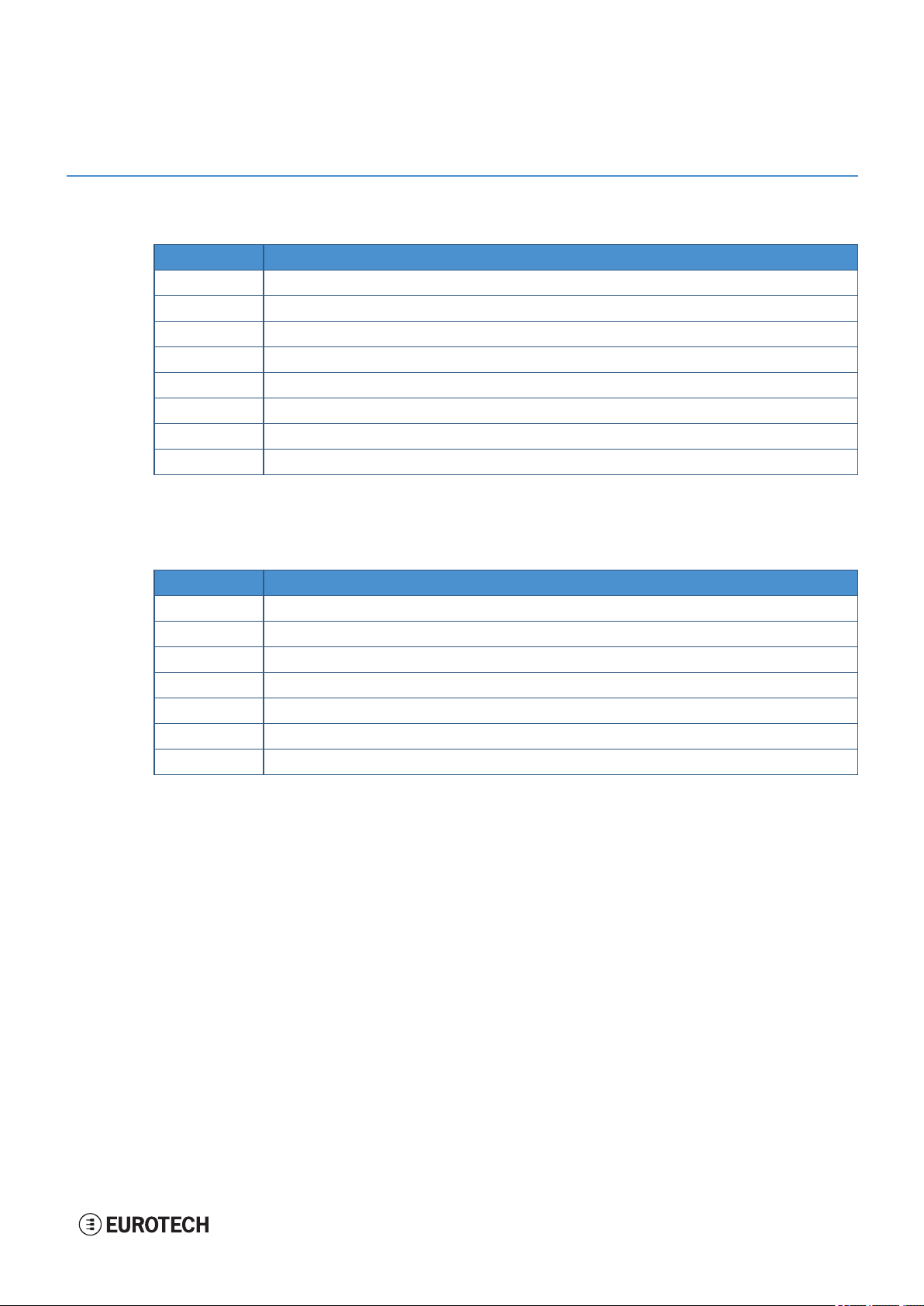
3.1 Conventions for signal names
Con vention Description
GND Ground
# Active low signal
+ Positive signal; Positive signal in differential pair
- Negative signal; Negative signalin differential pair
3.3 3.3 V signallevel
5 5 V signallevel
NC No Connection
Reserved Use is reserved to Eurotech
3.2 Conventions for signal types
Con vention Description
I Signal isan input to the system
O Signal is an output from the system
IO Signal may be input or output
P Power and Ground
A Analog signal
NC No Connection
Reserved Use is reserved to Eurotech
13 / 98

(This page has been intentionally left blank)

ReliaGATE 10-12 User manual Rev. 0-14 4 Getting started
4 GETTING STARTED
To get started with the ReliaGATE 10-12, follow these steps:
1. Know the ReliaGATE 10-12 interfaces.
The ReliaGATE 10-12 provides connectivity to several wired and wireless interfaces.
For further information, see:
l "Product overview" on page17
l "Technical specifications" on page19
l "Interfaces overview" on page29
l "Interfaces in detail" on page35
2. Supply power to the ReliaGATE 10-12.
Supply power to the ReliaGATE 10-12 correctly, respecting all the safety instructions.
For further information, see "How to supply power to the product" on page57
3. Log into the Administration console.
The ReliaGATE 10-12 runs a Linux distribution based on a Yocto framework and supports login via
a variety of methods.
For further information, see:
l "The Software" on page61
l "How to log in the Administration Console" on page79
l "How to access interfaces under Linux" on page63
4. Start developing your applications.
The ReliaGATE 10-12 supports ESF, which is an inclusive software framework that puts a
middleware layer between the operating system and the OEM application.
For detailed instructions, and sample applications for developing device applications using ESF on
Eurotech platforms, see: http://esf.eurotech.com/docs.
5. Install the ReliaGATE 10-12.
The ReliaGATE 10-12 is lightweight, compact, and easy to install.
For further information, see:
l "Mechanical specifications" on page87
l "How to install the product" on page89
6. Maintain the ReliaGATE 10-12.
Periodic maintenance of the ReliaGATE 10-12 ensures greater integrity and reliable operation.
For further information, see:
l "How to maintain the product" on page95
15 / 98

(This page has been intentionally left blank)
ReliaGATE 10-12 User manual Rev. 0-14 5 Product overview
5 PRODUCT OVERVIEW
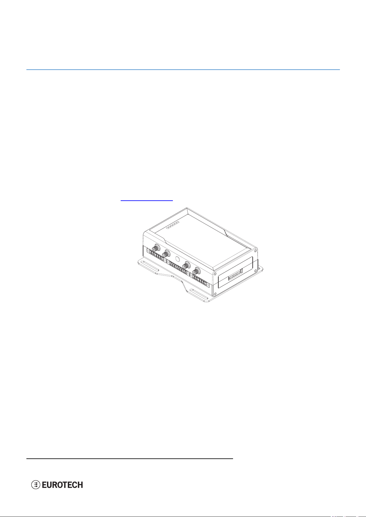
5.1 Product description
The ReliaGATE 10-12 is a family of IoT Edge Gateways designed to deliver LTE connectivity with 3G
fallback to industrial and lightly rugged applications.
The ReliaGATE 10-12 is based on the TI AM335x Cortex-A8 (Sitara) processor family, with 1GB of RAM,
4GB of eMMC and user-accessible MicroSD and dual Micro-SIM slots.
The ReliaGATE 10-12 features a wide range of connectivity capabilities1: it can integrate an internal LTE
Cat 1 modem with dual Micro-SIM support, Wi-Fi, Bluetooth Low Energy, and two Fast Ethernet ports; an
optional internal GNSS provides precise geolocation capabilities.
Expansion options include the ReliaCELL 10-20 family, consisting of external, rugged modules for global
mobile connectivity use that are certified by leading carriers. An expansion connector allows adding extra
features with side modules, such as the ReliaLORA 10-12, a LoRa Gateway unit, or the ReliaIO 10-12,
which provides analog input and more DI/O ports.
For further details visit www.eurotech.com.
Figure 5.1 - Example of ReliaGATE 10-12, front side
1
The features availability depends on the product versions
17 / 98

5 Product overview ReliaGATE 10-12 User manual Rev. 0-14
5.2 Intended use and not allowed uses of the product
NOTICE
Install this product in a secured location, only accessible to authorized personnel (for example
in a cabinet / technical compartment).
This product is intended for professional use and must only be installed by qualified personnel.
5.2.1 Intended use
The ReliaGATE 10-12 is a family of IoT Edge Gateways designed to deliver LTE connectivity with 3G
fallback to industrial and lightly rugged applications.
The ReliaGATE 10-12 must:
l Be installed in a secured location, only accessible to authorized personnel (for example in a cabinet
/ technical compartment), and not exposed to atmospheric agents
l Be used indoors only
l Be used with appropriate interconnecting and power cables
l Be used with an external DC power supply source that:
o
Must meet the requirements stated on the identification label of the product
o
Must deliver a maximum current of 2 A
l Include an external 2 A fuse on the line coming from the negative terminal of the DC power source.
5.2.2 Not allowed uses
Do not use the ReliaGATE 10-12:
l In automotive applications
l In railway applications
l In defence applications
l Outdoors
l In safety-critical applications
l In environments with potentially explosive atmospheres
l If not installed according to the instructions and warnings contained in this document.
18 / 98
ReliaGATE 10-12 User manual Rev. 0-14 5 Product overview
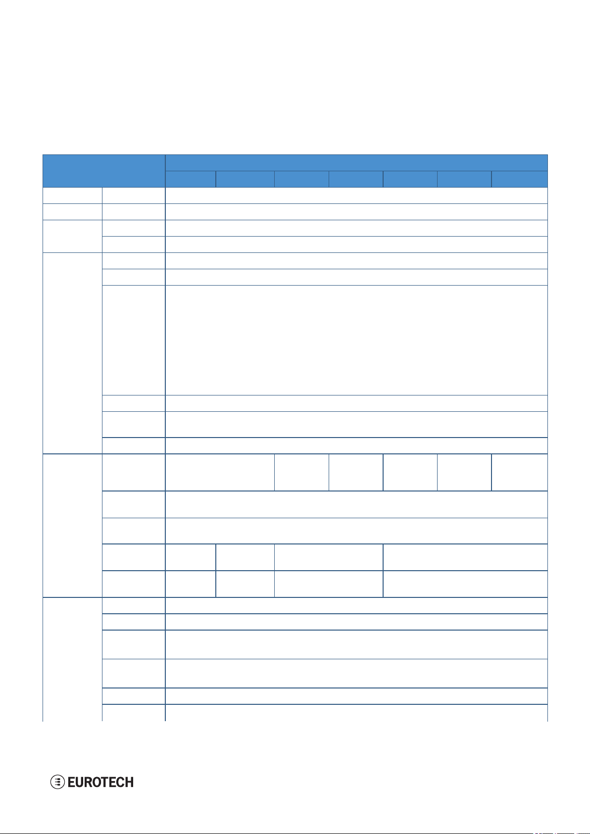
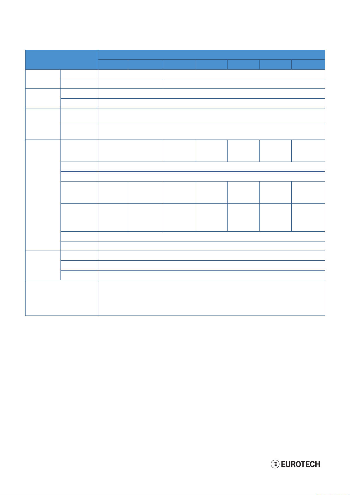
5.3 Technical specifications
The ReliaGATE 10-12 is available in several versions: from ReliaGATE 10-12-X1 to ReliaGATE 10-12-X7;
for example ReliaGATE 10-12-53.
They have the following specifications, according to the respective versions:
Specifications Description according to ReliaGATE 10-12-XY version s
-X1 -X2 -X3 -X4 -X5 -X6 -X7
Processor CPU TI AM3352, 1 GHz, 1 Cor e
Memory RAM 1 GB, DDR3
Storage Embedded 4 GB eMMC
Other 1x MicroSD slot (user accessible)
I/O
interfaces
Ethernet 2x F ast Ethernet on RJ45 connectors
USB 3x Host 2.0 (noise and surge protected) on Type A connectors
Serial
X ≤ 3 → 2x RS-232/485: COM 0/1; Surge pr otected, RS-485 termination and fail-safe resistors
(Default: RS-232)
1x T TL Serial Console
X ≥ 4 → 1x RS-422/485: COM 0; Surge protected, Insulated, Full / Half Duplex
(Default: RS-422 Full Duplex*)
1x RS-232/485: COM 1; Surge protected, RS-485 termination and fail-safe resistors
(Default: RS-232)
1x T TL Serial Console
*Factory Option: RS-485 Half Duplex set as default (RS-422 mode no longer available)
CAN 2.0B 2x CAN bus with 5V (100mA) Power Out
Digit al I/O 2xDigital Input: 36 V, 1 kV Optoinsulated
Expansion Yes, for Side Expansion Modules
Radio
interfaces
Other RTC Yes (user accessible backup battery)
Internal
Mobile
External
Mobile
GNSS Factory Option: Internal (72 channelsGPS, Galileo, GLONASS, BeiDou)
Wi-Fi/BT No 802.11a,b,g,n/
Antenn as
(external)
Watchdog Yes (system level)
TPM
No 2xRP-SMA
2x DigitalOutput: 40 V AC/DC, 1 kV Optoinsulated, 500 mA, 1 kHz Max Switching
No LTE Cat 1
(NA)
3G F allback
Optional Accessory: ReliaCELL 10-20 (3G/4G)
Optional Accessory: External ReliaCELL 10-20 3G
BLE 4.2
2x SMA Mobile Conn. 2x SMA Mobile Conn., 2x RP-SMA Wi-Fi/BT
Wi-Fi/BT
LTE Cat 1
(EU)
2G F allback
No 802.11a,b,g,n/
X ≤ 3 → Factory Option
X ≥ 4 → TPM 2.0
LTE Cat 1
(NA)
3G F allback
LTE Cat 1
(EU)
2G F allback
BLE 4.2
LTE Cat 1
(JP)
Accel/Gyro
Sensors Temperature (inside the product)
LEDs 1x Power, 1x Mobile Connectivity, 4x Programmable
X ≤ 3 → Accelerometer
X ≥ 4 → Accelerometer and Gyroscope
19 / 98
5 Product overview ReliaGATE 10-12 User manual Rev. 0-14
Specifications Description according to ReliaGATE 10-12-XY version s
-X1 -X2 -X3 - X4 -X5 -X6 -X7
Buttons 1x Reset, 1x Programmable
SIM slot No 2x Micro-SIM (user accessible)
Power Input Nominal: 12 or 24 VDC; Range: 9 to 36 VDC with transient protection and Ignition Sense
Con sumption 2 W typical; 15 W maximum
Environ ment Operating
-30 to +70 °C
Temp.
Storage
-40 to +85 °C
Temp.
Certificatio ns Regulatory FCC,
ISED,
FCC,
ISED
CE FCC,
ISED
CE JATE,
TELEC
CE
Safety EN 62368-1:2014+A11:2017
Environ mental RoHS2; REACH
Wi-Fi/BT
Radio
No FCC,
ISED,
FCC,
ISED
CE FCC,
ISED
CE JATE,
TELEC
CE
Mobile
Radio
No No FCC, ISED,
PTCRB
(AT&T,
Verizon)
CE FCC, ISED,
PTCRB
(AT&T,
Verizon)
CE JATE,
TELEC,
(NTT
DoCoMo)
Ingress IP20
MTBF > 375.000 h (prediction method: IEC 62380 @ 25°C GF)
Mechan ical Enclosure Material: ABS- Color: Aluminium
Dimensions 139 (L) x 115 (W) x 46 (H); mm - Antennas Connectors and Mounting Bracket included
Weight 210 g (without mounting kit/bracket)
Operating System
X = 0 or 4 → No Operating system
X = 1 or 5 → Yocto Linux*
X = 3 or 6 → Yocto Linux* + ESF
20 / 98
* Factory Option: Secure Boot - Yocto Linux
ReliaGATE 10-12 User manual Rev. 0-14 5 Product overview
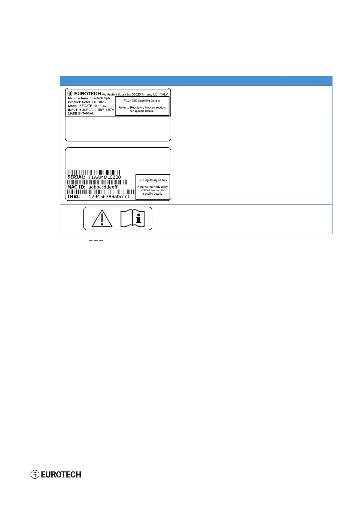
5.4 Product labels
The following labels are placed on the product:
Label example Label type and content Label positio n
Part Number Label
l Eurotech logo
l Manufacturer name
l Manufacturer address (EU versions only)
l Product number
l Model number (xx = product version)
l Power supply specifications*
l FCC information (NA versions only)
l ISED information (NA versions only)
On the underside of
the product
* the symbol stands for direct current
Serial Number Label
l Serial number
l MACID number
l IMEI number
l CE mark (EU versionsonly)
l WEEE symbol (EU versions only)
Batt ery Lab el
l War ning:
To avid battery hazards, refer to the section
"The RTC backup batter y" on page55
On the underside of
the product
On the internal side
of the Service Panel
cover
21 / 98

(This page has been intentionally left blank)
ReliaGATE 10-12 User manual Rev. 0-14 6 Norms and certifications
6 NORMS AND CERTIFICATIONS
6.1 CE marking
Some versions of the product described in this document are CE marked; for further
information see "Technical specifications" on page19.
Eurotech is not responsible for the use of this product together with equipment (for example:
power supplies, personal computers, etc.) that are not CE marked and not compliant with
the requirements specified in this document.
6.2 Directive 2014/30/EU (only for version: -X1)
This product meets the requirements of the Directive 2014/30/EU of the European Parliament and of the
Council of 26 February 2014 on the harmonization of the laws of the Member States relating to
electromagnetic compatibility.
6.2.1 Modification statement
Eurotech has not approved any changes or modifications to this product by the user. Any changes or
modifications could void the user’s authority to operate the product.
6.3 Directive RED 2014/53/EU (only for versions: -X2, -X4, -X6)
This product meets the requirements of the Directive 2014/53/EU of the European Parliament and of the
Council of 16 April 2014 on the harmonization of the laws of the Member States relating to the making
available on the market of radio equipment.
6.3.1 Modification statement
Eurotech has not approved any changes or modifications to this product by the user. Any changes or
modifications could void the user’s authority to operate the product.
6.4 FCC marking
Some versions of the product described in this document are FCC marked; for further
information see "Technical specifications" on page19.
Eurotech is not responsible for the use of this product together with equipment (for example:
power supplies, personal computers, etc.) that are not FCC marked and not compliant with
the requirements specified in this document.
6.5 FCC/ISEDregulatory notices
6.5.1 Modification statement
Eurotech has not approved any changes or modifications to this product by the user. Any changes or
modifications could void the user’s authority to operate the product.
Eurotech n’approuve aucune modification apportée à l’appareil par l’utilisateur, quelle qu’en soit la nature.
Tout changement ou modification peuvent annuler le droit d’utilisation de l’appareil par l’utilisateur.
23 / 98
6 Norms and certifications ReliaGATE 10-12 User manual Rev. 0-14
6.5.2 ISED Canada Regulatory Notices
This device contains licence-exempt transmitter(s)/receiver(s) that comply with Innovation, Science and
Economic Development Canada’s licence-exempt RSS(s). Operation is subject to the following two
conditions:
1. This device may not cause interference.
2. This device must accept any interference, including interference that may cause undesired
operation of the device.
L’émetteur/récepteur exempt de licence contenu dans le présent appareil est conforme aux CNR
d’Innovation, Sciences et Développement économique Canada applicables aux appareils radio exempts
de licence. L’exploitation est autorisée aux deux conditions suivantes:
1. L’appareil ne doit pas produire de brouillage;
2. L’appareil doit accepter tout brouillage radioélectrique subi, même si le brouillage est susceptible
d’en compromettre le fonctionnement.
This radio transmitter 21442-MRG1012 has been approved by Innovation, Science and Economic
Development Canada to operate with the antenna types listed below, with the maximum permissible gain
indicated. Antenna types not included in this list that have a gain greater than the maximum gain indicated
for any type listed are strictly prohibited for use with this device.
Le présent émetteur radio 21442-MRG1012 a été approuvé par Innovation, Sciences et Développement
économique Canada pour fonctionner avec les types d'antenne énumérés ci dessous et ayant un gain
admissible maximal. Les types d'antenne non inclus dans cette liste, et dont le gain est supérieur au gain
maximal indiqué pour tout type figurant sur la liste, sont strictement interdits pour l'exploitation de
l'émetteur.
Antenn a Types
Types d’an ten ne
Cellular
50Ω Dipole
Wi-Fi / Bluet oo th
50Ω Dipole
Frequency Band
Band e de fréqu ences
700 MHz
850 MHz
1700 MHz
1900 MHz
2.5 GHz Wi-F i 802.11a,b,g,n / BLE 4.2 BLE Bluetooth
5 GHz Wi-Fi 802.11a,b,g,n
The ReliaGATE 10-12 has been certified with the following antennas:
Le ReliaGATE 10-12 a été certifié avec les antennes suivantes:
Antenn a Types
Types d’an ten ne
Cellular
50Ω Dipole
Wi-Fi / Bluet oo th
50Ω Dipole
Frequency Band
Band e de fréqu ences
l T aoglas GSA.8827.A101111
l T aoglas MA.950.W.A.LBICG.005
l Linx Technologies ANT-DB1-RAF-RPS
l T aoglas MA.950.W.A.LBICG.005
Antenn a Gain
Gain de l' antenne
Taoglas MA.950:
Certified operation:
l 2.4GHz/5.8GHz MIMO_1 antenna is interfaced to
2.4GHz WiFi/Bluetooth RP-SMA
l 2.4GHz/5.8GHz MIMO_2 antenna is interfaced to
5GHz WiFi RP-SMA
Antenn a Gain
Gain de l' antenne
6.63 dBi
6.63 dBi
6.00 dBi
8.51 dBi
5.47 dBi
7.07 dBi
24 / 98
Opération certifiée:
l L’antenne 2.4GHz/5.8GHz MIMO_1 est connectée
au RP-SMA WiFi / Bluetooth à 2,4 GHz
l L’antenne 2.4GHz/5.8GHz MIMO_2 est connectée
au RP-SMA WiFi 5 GHz

ReliaGATE 10-12 User manual Rev. 0-14 6 Norms and certifications
6.5.3 RF radiation exposure statement
This product complies with FCC and ISED radiation exposure limits set forth for an uncontrolled
environment. The antenna should be installed and operated with minimum distance of 20 cm between the
radiator and your body.
Cet appareil est conforme aux limites d'exposition aux rayonnements de l’ISED pour un environnement
non contrôlé. L'antenne doit être installé de façon à garder une distance minimale de 20 centimètres entre
la source de rayonnements et votre corps.
This device and its antenna(s) must not be co-located or operating in conjunction with any other antenna or
transmitter except in accordance with FCC multi-transmitter product procedures.
Cet appareil et son (ses) antenne(s) ne doivent pas être co-localisés ou utilisés en conjonction avec une
autre antenne ou un autre émetteur, sauf en conformité avec les procédures du produit multi-émetteur de la
FCC.
6.5.4 FCC Class B digital device notice
This device complies with part 15 of the FCC Rules. Operation is subject to the following two conditions:
1. This device may not cause harmful interference, and
2. This device must accept any interference received, including interference that may cause undesired
operation.
Note: This equipment has been tested and found to comply with the limits for a Class B digital device,
pursuant to part 15 of the FCC Rules. These limits are designed to provide reasonable protection
against harmful interference in a residential installation. This product generates, uses and can radiate
radio frequency energy and, if not installed and used in accordance with the instructions, may cause
harmful interference to radio communications. However, there is no guarantee that interference will not
occur in a particular installation. If this product does cause harmful interference to radio or television
reception, which can be determined by turning the product OFF and ON, the user is encouraged to try
to correct the interference by one or more of the following measures:
l Reorient or relocate the receiving antenna
l Increase the separation between the product and the receiver
l Connect the product into an outlet on a circuit different from that to which the receiver is connected
l Consult the dealer or an experienced radio/TV technician for help
6.5.5 ISED Class B digital device notice
ICES-003 Class B Notice - Avis NMB-003, Classe B.
This Class B digital apparatus complies with Canadian ICES-003.
Cet appareil numérique de la classe B est conforme à la norme NMB-003 du Canada.
6.5.6 Labeling information
The following information is stated on the product labels:
l Contains FCC ID: RI7LE910NAV2
l Contains FCC ID: UKMMRG1012
l Contains IC ID: 5131A-LE910NAV2
l Contains IC ID: 21442-MRG1012
l CAN ICES-3 (B)/NMB-3(B)
25 / 98

6 Norms and certifications ReliaGATE 10-12 User manual Rev. 0-14
6.6 Restrictions on 5 GHz Wi-Fi usage
Chan nel Number Frequency (MHz) Europe (ETSI) North America (FCC)
36 5180 Indoor Usage Only Indoor Usage Only
40 5200 Indoor Usage Only Indoor Usage Only
44 5220 Indoor Usage Only Indoor Usage Only
48 5240 Indoor Usage Only Indoor Usage Only
52 5260 Not Supported Not Supported
56 5280 Not Supported Not Supported
60 5300 Not Supported Not Supported
64 5320 Not Supported Not Supported
100 5500 Not Supported Not Supported
104 5520 Not Supported Not Supported
108 5540 Not Supported Not Supported
112 5560 Not Supported Not Supported
116 5580 Not Supported Not Supported
120 5600 Not Supported Not Supported
124 5620 Not Supported Not Supported
128 5640 Not Supported Not Supported
132 5660 Not Supported Not Supported
136 5680 Not Supported Not Supported
140 5700 Not Supported Not Supported
149 5745 Not Supported Supported
153 5765 Not Supported Supported
157 5785 Not Supported Supported
161 5805 Not Supported Supported
165 5825 Not Supported Supported
6.6.1 EU Restrictions on 5 GHz Wi-Fi Usage
Due to EU restrictions on 5 GHz Wi-Fi bands the ReliaGATE 10-12 is limited to indoor operation and
should only be operated in the frequency band 5150 MHz – 5250 MHz (U-NII-1) covering 20 MHz channels
(36,40,44,48) and 40 MHz channels(38,46).
Dynamic Frequency selection (DFS) as master or slave is not supported by the ReliaGATE 10-12.
6.6.2 FCC Restrictions on 5 GHz Wi-Fi Usage
Due to FCC restrictions on 5 GHz Wi-Fi bands the ReliaGATE 10-12 is limited to indoor operation within
the frequency band 5150 MHz – 5250 MHz (U-NII-1) covering 20 MHz channels (36,40,44,48) and 40 MHz
channels(38,46).
Dynamic Frequency selection (DFS) as master or slave is not supported by the ReliaGATE 10-12.
26 / 98
ReliaGATE 10-12 User manual Rev. 0-14 6 Norms and certifications
6.7 Antennas list
The ReliaGATE 10-12 has been certified with the following antennas:
Antenn a Types ReliaGATE 10-12-XY Versio ns Manufacturer and Part Number
Wi-Fi / Bluet oo th -X2, -X5, -X6 l Linx TechnologiesANT-DB1-RAF-RPS
Mobile con nectivity -X3, -X5, -X5, -X6 l Taoglas GSA.8827.A101111
NOTICE
Within the EU, antennas have to be used in compliance with the RED requirements.
Within the US/Canada, antennas have to be used in compliance with the FCC/ISED
requirements.
l T aoglas MA.950.W.A.LBICG.005
l T aoglas MA.950.W.A.LBICG.005
6.8 RoHS 3 compliance
This product, including all its components and its sub-assemblies, have been manufactured in compliance
with the Directive 2011/65/EU of the European Parliament and of the Council of 8 June 2011 on the
restriction of the use of certain hazardous substances in electrical and electronic equipment.
6.9 WEEE compliance
In compliance with the Directive 2012/19/EU of the European Parliament and of the Council
of 4 July 2012 on waste electrical and electronic equipment (WEEE), the symbol on the right,
shown on the product or within its literature, indicates separate collection for electrical and
electronic equipment (EEE) that has been placed on the market after 2005.
The product described in this document, at the end of its life cycle, must be collected
separately and managed in accordance with the provisions of the current Directive on waste
of electrical and electronic equipment.
Because of the substances present in the product, improper disposal can cause damage to
human health and to the environment.
To avoid any possible legal implications, contact your local waste collection body for full
collect and recycling information.
27 / 98

(This page has been intentionally left blank)
ReliaGATE 10-12 User manual Rev. 0-14 7 Interfaces overview
7
8
6
3
4
1
2
5
7 INTERFACES OVERVIEW
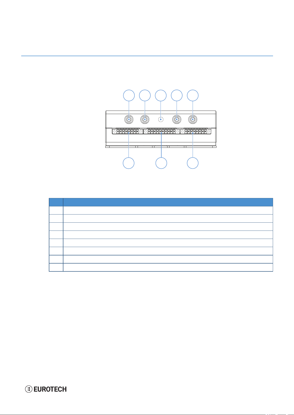
7.1 Front side overview
The front side layout is the following:
Figure 7.1 - Front panel interfaces layout
Ref# Description
1 2.4 GHz Wi-Fi / Bluetooth antenna connector (only for versions: -X2, -X5, -X6, -X7)
2 Internal Main Mobile antenna connector (only for versions: -X3, -X4, -X5, -X6, -X7)
3 Reserved for factory optional GlobalNavigation Satellite System (GNSS)
4 Internal DiversityMobile antenna connector (only for versions: -X3, -X4, -X5, -X6, -X7)
5 5 GHz Wi-Fi antenna connector ( only for versions: -X2, -X5, -X6, -X7)
6 CAN 0/1 connector
7 COM 0/1 connector
8 DigitalI/Os connector
Table 7.1 - Rear panel interfaces descript ion
29 / 98
7 Interfaces overview ReliaGATE 10-12 User manual Rev. 0-14
1
2
3
4
6
5
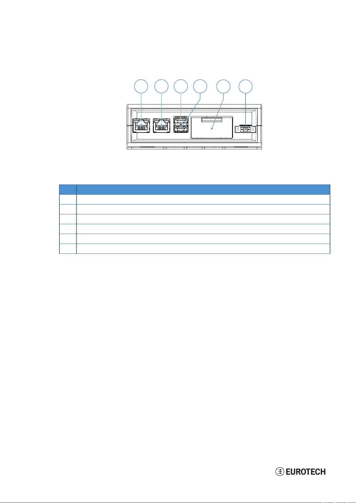
7.2 Rear side overview
The rear side layout is the following:
Figure 7.2 - Rear panel interfaces layout
Ref# Description
1 Ethernet ETH 1 connector
2 Ethernet ETH 0 connector
3 USB 0 connector
4 USB 1 connector
5 Service Panel
6 Power IN connector
Table 7.2 - Rear panel interfaces descript ion
30 / 98

ReliaGATE 10-12 User manual Rev. 0-14 7 Interfaces overview
2
689 7
1
4
5
3
7.2.1 Service Panel interfaces
The interfaces available in the Service Panel are the following:
Figure 7.3 - Service Panel interfaces layo ut
Ref# Description
1 Combo MicroSD + MicroSIM cards receptacle; pull-lever
2 RTC battery connection jumper
3 Boot selection jumper
4 DIP-switch for serial por ts configuration
5 Programmable pushbutton
6 TTL Serial console
7 Hardwar e reset pushbutton
8 RTC user accessible backup battery
9 MicroSIM card receptacle; push-pull
Table 7.3 - Service Panel interfaces d escription
31 / 98

7 Interfaces overview ReliaGATE 10-12 User manual Rev. 0-14
1
7.3 Right side overview
The right side layout is the following:
Figure 7.4 - Expansion connector
Ref# Description
1 Expansion Connector
Table 7.4 - Expansio n connector description
For further details see: "Expansion connector" on page52
32 / 98

ReliaGATE 10-12 User manual Rev. 0-14 7 Interfaces overview
1
7.4 Left side overview
The left side layout is the following:
Figure 7.5 - Expansion USB co nnector layout
Ref# Description
1 2.0 Host USB connector (ready to interface optional USB accessories, e.g.: ReliaCELL 10-20)
Table 7.5 - Expansio n USB con nector d escription
33 / 98

7 Interfaces overview ReliaGATE 10-12 User manual Rev. 0-14
6
1
7.5 LED indicators overview
The LED indicators are placed on the bottom side of the product. They are the following:
Figure 7.6 - LED indicators layout
Ref# Use Colo r
1 USER1 (General purpose) Green
2 USER2 (General purpose) Green
3 USER3 (General purpose) Amber
4 USER4 (General purpose) Amber
5 CELLULAR (Mobile modem activity; only for versions: -X3, -X4, -X5, -X6, -X7) :
6 POWER:
l LED ON: Modem ON
l LED blinking: Modem connected to cellular network
l LED ON: Product powered by the external source
l LED OFF: Product not powered by the external source
Table 7.6 - LED indicators description
Green
Blue
34 / 98

ReliaGATE 10-12 User manual Rev. 0-14 8 Interfaces in detail
8 INTERFACES IN DETAIL
8.1 Wi-Fi and Bluetooth (only for versions: -X2, -X5, -X6, -X7)
The ReliaGATE 10-12 provides the following Wi-Fi / Bluetooth functionality:
l 2.5 GHz Wi-Fi 802.11a,b,g,n / BLE 4.2 BLE Bluetooth
l 5 GHz Wi-Fi 802.11a,b,g,n
The internal circuitry allows for 2.5 GHz Wi-Fi and Bluetooth coexistence.
The Wi-Fi and Bluetooth antennas connectors are placed on the front side.
8.1.1 Wi-Fi specifications
l Integrated 2.4 & 5G GHz Power Amplifier (PA) for WLAN solution
l WLAN Baseband Processor and RF transceiver Supporting IEEE Std 802.11a/b/g/n
l WLAN 2.4/5 GHz SISO (20/40 MHz channels)
l Baseband Processor
o
IEEE Std 802.11a/b/g/n data rates and IEEE Std 802.11n data rates with 20 or 40 MHz
SISO
l Fully calibrated system. Production calibration not required
l Medium Access Controller (MAC)
o
Embedded ARM™ Central Processing Unit (CPU)
o
Hardware‐Based Encryption/Decryption using 64‐, 128‐, and 256‐Bit WEP, TKIP or AES
Keys
o
Supports requirements for Wi‐Fi Protected Access (WPA and WPA2.0) and IEEE Std
802.11i (includes hardware‐accelerated Advanced Encryption Standard (AES))
o
Designed to work with IEEE Std 802.1x
l IEEE Std 802.11d,e,h,i,k,r PICS compliant
l New advanced co‐existence scheme with BT/BLE
l 2.4/5 GHz Radio
o
Internal LNA and PA
o
Supports: IEEE Std 802.11a, 802.11b, 802.11g and 802.11n
l Supports 4 bit SDIO host interface, including high speed (HS) and V3 modes.
8.1.1.1 2.4 GHZ TX output power
Maximum RMS output power measured at 1dB from IEEE spectral mask or EVM.
Parameter Value
Operation frequency range 2412 to 2484 MHz
Output Power 17 dBm @ condition: 1 Mbps DSSS
8.1.1.2 5 GHZ TX output power
Maximum RMS output power measured at 1dB from IEEE spectral mask or EVM.
Parameter Value
Operation frequency range 4910 to 5825MHz
Output Power 16.8 dBm @ condition: 6 Mbps OFDM
35 / 98

8 Interfaces in detail ReliaGATE 10- 12 User manual Rev. 0- 14
1
2
8.1.2 Bluetooth specifications
l Supports Bluetooth 4.2
l Includes concurrent operation and built -in coexisting and prioritization handling of Bluetooth, BLE,
audio processing and WLAN
l Dedicated Audio processor supporting on chip SBC encoding + A2DP:
o
Assisted A2DP (A3DP) support - SBC encoding implemented internally
o
Assisted WB-Speech (AWBS) support - modified SBC codec implemented internally
8.1.3 BLE specifications
l Fully compliant with BT and BLE dual mode standard
l Support for all roles and role-combinations, mandatory as well as optional
l Supports up to 10 BLE connections
l Independent buffering for LE allows having large number of multiple connections without affecting
BR/EDR performance
8.1.4 Wi-Fi and Bluetooth antennas connectors specifications
Specifications are the same for both the following antennas connectors:
l 2.4 GHz Wi-Fi / Bluetooth
l 5 GHz Wi-Fi
Con nector Layout:
Con nector Specifications:
l RP-SMAconnector
l Gender: Female
Mating Connector Specifications:
l RP-SMAconnector
l Gender: Male
Con nector Pinout:
Pin # Description
1 Male inner pin contact
2 Female connector body (outer thread)
36 / 98

ReliaGATE 10-12 User manual Rev. 0-14 8 Interfaces in detail
8.2 Internal mobile connectivity (only for versions: -X3, -X4, X5, -X6, -X7)
The ReliaGATE 10-12 supports the following TELIT LE910 V2 modem variants, according to product
versions based on the geographic area of usage:
ReliaGATE 10-12-XY Versio n TELIT LE910 V2 variant Technology
-X3, -X5 LE910-NA1 - North America LTE Cat 1 3G Fallback
-X4, -X6 LE910-EU1 - Europe LTE Cat 1 2G Fallback
-X7 LE910-JP1 - Japan LTE Cat 1
The antennas connectors are placed on the front side.
8.2.1 Internal modem specifications (according to product versions)
8.2.1.1 Product features
l Rx Diversity and MIMO DL 2x2
l LTE FDD Cat.1, 3GPP release 9 compliant
l Serial port multiplexer 3GPP TS27.010
l Built in UDP/TCP/FTP/SMTP stack
l IP stack with TCP and UDP protocol
8.2.1.2 LTE data
l Uplink up to 5 Mbps
l Downlink up to 10 Mbps
8.2.1.3 Supported bands
Technology 4G b ands 3G bands 2G band s
LTE Cat 1 (NA) 3G Fallb ack FDD B2, B4, B5, B12, B13 B2, B5 -
LTE Cat 1 (EU) 2G Fallback FDD B1, B3, B7, B8, B20 - GSM 900, DCS 1800
LTE Cat 1 (JP) FDD B1, B19, B21 - -
8.2.1.4 TX output power
Band Power Class
LTE All Bands Class3 (0.2W)
WCDMA All Bands Class 3 (0.25W)
GSM 900 Class 4 (2W)
DCS 1800 Class 1 (1W)
37 / 98

8 Interfaces in detail ReliaGATE 10- 12 User manual Rev. 0- 14
8.2.1.5 Main antenna requirements
NA version
Feature Value
Frequency range Depending by the frequency band(s) provided by the network operator
Band width 140 MHz in LTE/WCDMA Band 2
Impedance 50 Ohm
Input power > 24dBm Average power
VSWR absolute max ≤ 10:1 (limit to avoid permanent damage)
VSWR recommended ≤ 2:1 (limit to fulfill all regulatory requirements)
445 MHz in LTE Band 4
70 MHz in LTE/WCDMA Band 5
47 MHz in LTE Band 12
41 MHz in LTE Band 13
EU version
Feature Value
Frequency range Depending by the frequency band(s) provided by the network operator
Band width 250 MHz in LTE/WCDMA Band 1
Impedance 50 Ohm
Input power > 24dBm Average power
VSWR absolute max ≤ 10:1 (limit to avoid permanent damage)
VSWR recommended ≤ 2:1 (limit to fulfill all regulatory requirements)
170 MHz in LTE/WCDMA Band 3 / DCS1800
190 MHz in LTE Band 7
80 MHz in LTE/WCDMA Band 8 / GSM900
71 MHz in LTE Band 20
JP version
Feature Value
Frequency range Depending by the frequency band(s) provided by the network operator
Band width 250 MHz in LTE Band 1
Impedance 50 Ohm
Input power > 24dBm Average power
VSWR absolute max ≤ 10:1 (limit to avoid permanent damage)
VSWR recommended ≤ 2:1 (limit to fulfill all regulatory requirements)
60 MHz in LTE Band 19
63 MHz in LTE Band 21
38 / 98

ReliaGATE 10-12 User manual Rev. 0-14 8 Interfaces in detail
8.2.1.6 Second antenna requirements (for antenna diversity)
NA version
Feature Value
Frequency range Depending by the frequency band(s) provided by the network operator
Band width 60 MHz in LTE/WCDMA Band 2
Impedance 50 Ohm
VSWR recommended ≤ 2:1 (limit to obtain the maximum sensitivity)
45 MHz in LTE Band 4
25 MHz in LTE/WCDMA Band 5
15 MHz in LTE Band 12
10 MHz in LTE Band 13
EU version
Feature Value
Frequency range Depending by the frequency band(s) provided by the network operator
Band width 60 MHz in LTE/WCDMA Band 1
Impedance 50 Ohm
VSWR recommended ≤ 2:1 (limit to obtain the maximum sensitivity)
75 MHz in LTE/WCDMA Band 3 / DCS1800
70 MHz in LTE Band 7
35 MHz in LTE/WCDMA Band 8 / GSM900
30 MHz in LTE Band 20
JP version
Feature Value
Frequency range Depending by the frequency band(s) provided by the network operator
Band width 60 MHz in LTE Band 1
Impedance 50 Ohm
VSWR recommended ≤ 2:1 (limit to obtain the maximum sensitivity)
15 MHz in LTE Band 19
15 MHz in LTE Band 21
39 / 98

8 Interfaces in detail ReliaGATE 10- 12 User manual Rev. 0- 14
1
2
8.2.2 Internal mobile antennas connectors specifications
Specifications are the same for both the following:
l Main Antenna Connector
l Diversity Antenna Connector
Con nector Layout:
Con nector Specifications:
l SMAconnector
l Gender: Female
Mating Connector Specifications:
l SMAconnector
l Gender: Male
Con nector Pinout:
Pin # Description
1 Female inner pin contact
2 Female connector body (outer thread)
40 / 98

ReliaGATE 10-12 User manual Rev. 0-14 8 Interfaces in detail
8.3 The MicroSIM card receptacles
The ReliaGATE 10-12 includes the following MicroSIM card receptacles in the Service Panel:
1st MicroSIM card receptacle: Integrated in a Combo MicroSD + MicroSIM cards receptacle (pull-
lever) on the top side of the circuit board
2nd MicroSIM card receptacle: On the bottom side of the circuit board (push-pull)
NOTICE
TURN THE SIM PIN OFF BEFORE INSERTING THE SIM CARD IN THE RECEPTACLE.
THE MOBILE CONNECTION WILL NOT WORK IF THE SIM PIN IS ON.
8.3.1 How to insert / remove the MicroSIM card
8.3.1.1 If you are using the receptacle on the top side of the circuit board
To insert the MicroSIM card, push it in the holder with the contacts facing down, and the cut corner facing
inwards:
To remove the MicroSIM card, pull the eject lever towards yourself: use a pen tip to simplify the operation:
41 / 98

8 Interfaces in detail ReliaGATE 10- 12 User manual Rev. 0- 14
8.3.1.2 If you are using the receptacle on the bottom side of the circuit board
To insert the MicroSIM card, push it in the holder with the contacts facing up, and the cut corner facing
inwards.
To remove the MicroSIM card, pull it out from the holder: use a pair of tweezers to simplify the operation.
42 / 98

ReliaGATE 10-12 User manual Rev. 0-14 8 Interfaces in detail
Digital Input
Cathode
Digital Input
Anode
VCC3
GPIN
8.4 Digital I/Os
The ReliaGATE 10-12 provides the following Digital I/Os:
l 2x Digital Input: 36 V, 1 kV Optoinsulated
l 2x Digital Output: 40 V AC/DC, 1 kV Optoinsulated, 500 mA, 1 kHz Max Switching
The Digital I/Os connector is available on the front side.
8.4.1 Insulated Digital Inputs
8.4.1.1 Electrical specifications
The table below shows the electrical specifications of the digital inputs:
Charact eristic Value
Logic Zero 0 V ≤ VIN_low ≤ 1 V
Logic One 2 V ≤ VIN_high ≤ 36 V
Input Current < 3.5 mA
8.4.1.2 Electrical schematics
The figure below shows the electrical schematics of one digital input:
43 / 98

8 Interfaces in detail ReliaGATE 10- 12 User manual Rev. 0- 14
VCC3
GPOUT
Digital Output
Normally Open
Digital Output
Common
8
1
8.4.2 Insulated Digital Outputs
8.4.2.1 Electrical specifications
The table below shows the electrical specifications of the digital outputs:
Charact eristic Value
Maximum Voltage 40 V
Maximum Current 500 mA
Output ON Resistance Typical: 0.83 Ohm
>Maximum switch ing freq uency 1 kHz
8.4.2.2 Electrical schematics
The illustration below shows the electrical schematics of one digital output:
Maximum: 2.50 Ohm
8.4.3 Digital I/Os connector specifications
Con nector Layout:
Con nector Specifications:
l Base strip, Header
l Gender: Female
l T ype: 8-pin, 3.5 mm pitch
Mating Connector Specifications:
l Pluggable screw terminal block;
l Gender: Male
l T ype: 8-pin, 3.5 mm pitch
l Example:
Manufacturer: Phoenix Contact
Part Number: MC 1,5/ 8-STF-3,5 - 1847181
(or equivalent)
Con nector Pinout:
Pin # Signal Type Descript ion
1 DigitalOUT: 1COM O Digital Output 1
Common
2 DigitalOUT: 1NO O DigitalOutput 1
NormallyOpen
3 DigitalOUT: 2COM O Digital Output 2
Common
4 DigitalOUT: 2NO O DigitalOutput 2
NormallyOpen
5 DigitalIN: 1A I Digital Input 1 Anode
6 DigitalIN: 1C I Digital Input 1 Cathode
7 DigitalIN: 2A I Digital Input 2 Anode
8 DigitalIN: 2C I Digital Input 2 Cathode
44 / 98

ReliaGATE 10-12 User manual Rev. 0-14 8 Interfaces in detail
8.5 COM ports 0 and 1 for ReliaGATE 10-12-XY with X ≤ 3
The ReliaGATE 10-12 provides the following COM ports:
l 2x RS-232/485: COM 0/1; Surge protected, RS-485 termination and fail-safe resistors
(Default: RS-232)
COM ports specifications:
l The COM ports are surge protected
l Each port has 2 pairs of pins (each signal is doubled)
l Both COM ports are disabled when the ReliaGATE is initially powered ON
l To set the RS-232/485 modes see "How to set the RS-232/485 modes" on page68
l Maximum supported baud rates are:
o
For RS-232 mode: up to 450 kbps
o
For RS-485 mode: up to 1.75 Mbps
The COM 0/1 connectors are available on the front side.
8.5.1 Note for termination resistors (only for RS-485 mode)
Each port has 2 pairs of pins (each signal is doubled):
l If the ReliaGATE 10-12 is located at the beginning, or at the end, of a RS-485 chain, spare pair of
pins can be used to connect permanently standard axial resistor 120 Ohm, if the application requires
that
l If the ReliaGATE 10-12 is not at the beginning or at end of the RS-485 chain, two options are
available:
o
Option 1: one pair of pins can remain not connected
o
Option 2: one pair of pins can be used to connect the previous device of the chain,
and the other pair can be used to connect the following device of the chain
8.5.2 Note for fail safe resistors (only for RS-485 mode)
To insert the RS-485 fail-safe resistors, use the DIP switch available in the Service Panel.
8.5.2.1 Switches meaning
Default DIP switch configuration is OFF; this means no resistors inserted.
SW# Signal Description
1 RS232_RX/485_D+ Line ON: 4.7 kΩ pull-up resistor inserted on COM 0
2 RS232_TX/485_D- Line ON: 4.7 kΩ pull-down resistor inserted on COM 0
3 RS232_RX/485_D+ Line ON: 4.7 kΩ pull-up resistor inserted on COM 1
4 RS232_TX/485_D- Line ON: 4.7 kΩ pull-down resistor inserted on COM 1
45 / 98

8 Interfaces in detail ReliaGATE 10- 12 User manual Rev. 0- 14
1 10
8.5.3 COM connector specifications
Con nector Layout:
Con nector Specifications:
l Base strip, Header
l Gender: Male
l T ype: 10-pin, 3.5 mm pitch
Mating Connector Specifications:
l Pluggable screw terminal block;
l Gender: Female
l T ype: 10-pin, 3.5 mm pitch
l Example:
Manufacturer: Shenzhen Connection ElectronicsCo., Ltd.
Part Number: MC 1,5/10-STF-3,5 - 1847204
(or equivalent)
Con nector Pinout:
Pin # Signal Type Description
1 COM 0: T X/D- O COM port 0:
l RS-232: Transmit Data
l RS-485: B (D- Line)
2 COM 0: RX/D+ I COMport 0:
l RS-232: ReceiveData
l RS-485: A (D+ Line)
3 COM 0: GND P Ground (not isolated)
4 COM 0: RX/D+ I COMport 0:
l RS-232: ReceiveData
l RS-485: A (D+ Line)
5 COM 0: T X/D- O COM port 0:
l RS-232: Transmit Data
l RS-485: B (D- Line)
6 COM 1: T X/D- O COM port 1:
l RS-232: Transmit Data
l RS-485: B (D- Line)
7 COM 1: RX/D+ I COMport 1:
l RS-232: ReceiveData
l RS-485: A (D+ Line)
8 COM 1: GND P Ground (not isolated)
9 COM 1: RX/D+ I COMport 1:
l RS-232: ReceiveData
l RS-485: A (D+ Line)
10 COM 1: TX/D- O COM port 1:
l RS-232: Transmit Data
l RS-485: B (D- Line)
46 / 98

ReliaGATE 10-12 User manual Rev. 0-14 8 Interfaces in detail
8.6 COM ports 0 and 1 for ReliaGATE 10-12-XY with X ≥ 4
The ReliaGATE 10-12 provides the following COM ports:
l 1x RS-422/485: COM 0; Surge protected, Insulated, Full Duplex / Half Duplex
(Default: RS-422 Full Duplex)
l 1x RS-232/485: COM 1; Surge protected, RS-485 termination and fail-safe resistors
(Default: RS-232)
COMports specifications:
l The COM ports are surge protected
l Both COM ports are disabled when the ReliaGATE is initially powered ON
l To set the RS-232/485 modes see "How to set the RS-232/485 modes" on page68
l Maximum supported baud rates are:
o
For RS-232 mode: up to 450 kbps
o
For RS-485 mode: up to 1.75 Mbps
The COM 0/1 connectors are available on the front side.
For further information, see: "COM ports 0 and 1, Console port " on page68
8.6.1 Note for termination resistors (only for COM 1 in RS-485 mode)
COM 1 has 2 pairs of pins (each signal is doubled):
l If the ReliaGATE 10-12 is located at the beginning, or at the end, of a RS-485 chain, spare pair of
pins can be used to connect permanently standard axial resistor 120 Ohm, if the application requires
that
l If the ReliaGATE 10-12 is not at the beginning or at end of the RS-485 chain, two options are
available:
o
Option 1: one pair of pins can remain not connected
o
Option 2: one pair of pins can be used to connect the previous device of the chain,
and the other pair can be used to connect the following device of the chain
8.6.2 Note for fail safe resistors (only for COM 1 for RS-485 mode)
To insert the RS-485 fail-safe resistors, use the DIP switch available in the Service Panel.
8.6.2.1 Switches meaning
Default DIP switch configuration is OFF; this means no resistors inserted.
SW # Signal Description
1 RS232_RX/485_D+ Line ON: 4.7 kΩ pull-up resistor inserted on COM 1
2 RS232_TX/485_D- Line ON: 4.7 kΩ pull-down resistor inserted on COM 1
47 / 98

8 Interfaces in detail ReliaGATE 10- 12 User manual Rev. 0- 14
1 10
8.6.3 COM connector specifications
Con nector Layout:
Con nector Specifications:
l Base strip, Header
l Gender: Male
l T ype: 10-pin, 3.5 mm pitch
Mating Connector Specifications:
l Pluggable screw terminal block;
l Gender: Female
l T ype: 10-pin, 3.5 mm pitch
l Example:
Manufacturer: Shenzhen Connection ElectronicsCo., Ltd.
Part Number: MC 1,5/10-STF-3,5 - 1847204
(or equivalent)
Con nector Pinout:
Pin # Signal Type Description
1 COM 0: Y/D+ O COM port 0:
l RS-422: Y (+OUT)
l RS-485: A (D+ Line)
2 COM 0: Z /D- I COM port 0:
l RS-422: Z (-OUT)
l RS-485: B (D- Line)
3 COM 0: ISO GND P Ground (isolated)
4 COM 0: A/D+ I COM port 0:
l RS-422: A(+IN)
l RS-485: A (D+ Line)
5 COM 0: B/D- O COM port 0:
l RS-422: B(-IN)
l RS-485: B (D- Line)
6 COM 1: T X/D- O COM port 1:
l RS-232: Transmit Data
l RS-485: B (D- Line)
7 COM 1: RX/D+ I COM port 1:
l RS-232: ReceiveData
l RS-485: A (D+ Line)
8 COM 1: GND P Ground (not isolated)
9 COM 1: RX/D+ I COM port 1:
l RS-232: ReceiveData
l RS-485: A (D+ Line)
10 COM 1: TX/D- O COM port 1:
l RS-232: Transmit Data
l RS-485: B (D- Line)
8.6.4 Note for RS-485 Half Duplex (only for COM 0 in RS-485 mode)
To set an RS-485 connection in Half Duplex, add the following external loop-back:
connect pin 1 to pin 4, and pin 2 to pin 5.
Then: pins 1 and 4 are: D+ Line (A/Y); pins 2 and 5 are: D- Line (B/Z).
As factory option, the RS-485 Half Duplex mode can be set as default configuration. With this setup, the
RS-422 mode is no longer available.
48 / 98

ReliaGATE 10-12 User manual Rev. 0-14 8 Interfaces in detail
8
1
8.7 CAN ports 0 and 1
The ReliaGATE 10-12 provides 2x CAN (Controller Area Network) ports compliant with the CAN
Specification 2.0, Parts A and B:
l CAN 0
l CAN 1
The CAN 0/1 connectors are available on the front side.
Notes about CANpower supply:
l The ReliaGATE 10-12 can supply power to the 2 CAN ports: 100 mA @ 5V (each port)
l CAN power can be enabled / disabled by software
l The interfaces are surge protected.
8.7.1 CAN 0/1 connector specifications
Con nector Layout:
Con nector Specifications:
l Base strip, Header
l Gender: Male
l T ype: 8-pin, 3.5 mm pitch
Mating Connector Specifications:
l Pluggable screw terminal block;
l Gender: Female
l T ype: 8-pin, 3.5 mm pitch
l Example:
Manufacturer: Phoenix Contact
Part Number: MC 1,5/ 8-STF-3,5 - 1847181
(or equivalent)
Con nector Pinout:
Pin # Signal Type Descript ion
1 CAN 0: H IO CAN port 0 Positive Data
2 CAN 0: L IO CAN por t 0 Negative Data
3 CAN 0: 5V 5 CAN node 0
5 V Output power supply
4 CAN 0: GND P Ground
5 CAN 1: H IO CAN port 1 Positive Data
6 CAN 1: L IO CAN por t 1 Negative Data
7 CAN 1: 5V 5 CAN node 1
5 V Output power supply
8 CAN 1: GND P Ground
49 / 98

8 Interfaces in detail ReliaGATE 10- 12 User manual Rev. 0- 14
1
8.8 Ethernet ETH 0 and 1
The ReliaGATE 10-12 provides 2x 10/100 Mbps Ethernet ports for wired network connectivity:
l ETH 0
l ETH 1
The ETH 0/1 connectors are available on the rear side.
8.8.1 Ethernet specifications
Feature Description
Network Stand ard IEEE 802.3u 10/100-BaseTX.
Speeds 10/100-BaseTX interfaces with MAC
Notes The interfaces are noise and surge protected.
8.8.2 ETH 0/1 connectors specifications
IEEE 802.3x full-duplex flow control.
The RJ-45 connector has integrated magnetics.
Con nector Layout:
Con nector Specifications:
l RJ-45 socket
l Gender: Female
Mating Connector Specifications:
l RJ-45 plug
l Gender: Male
Con nector Pinout (pins not listed are not connected):
Pin # Signal Typ e Description
1 TX+ O Tr ansmit Data +
2 TX- O Transmit Data -
3 RX+ I Receive Data +
6 RX- I Receive Data -
50 / 98

ReliaGATE 10-12 User manual Rev. 0-14 8 Interfaces in detail
1
8.9 Host USB ports
The ReliaGATE 10-12 provides 3x Host 2.0 USB ports (Noise and Surge Protected) for general purpose
applications:
l USB 0 on the front side; max load: 500 mA
l USB 1 on the front side; max load: 500 mA
l USB 2 on the left side; max load: 1 A (ready to interface optional USB accessories, e.g.: ReliaCELL
10-20)
8.9.1 USB 0/1/2 connectors specifications
Con nector Pinout:
Con nector Specifications:
l USB Type-A socket
l Gender: Female
Mating Connector Specifications:
l USB Type-A plug
l Gender: Male
Con nector Pinout (pins not listed are not connected):
Pin # Signal Typ e Description
1 VBUS 5 +5V
2 D- IO Negative data
3 D+ IO Positive data
4 DGND P Ground
51 / 98

8 Interfaces in detail ReliaGATE 10- 12 User manual Rev. 0- 14
1
2
23
24
8.10 Expansion connector
The ReliaGATE 10-12 provides an expansion connector for the following:
l Additional USB OTG interface
2
l I
S Audio interface
l GPIO expansion interface
2
l I
C interface
l SPI interface
The expansion connector is available on the right side.
8.10.1 Expansion connector specifications
Con nector Layout:
Con nector Specifications:
l SQT Socket
l Gender: Female
l T ype: 12*2-pin; 2.0 mm pitch
Mating Connector Specifications:
l Samtec MT MM Housing
l Gender: Male
l T ype: 12*2-pin; 2.0 mm pitch
l Example:
Manufacturer: Samtec
Part Number: MTMM-112-07-L-D-3
(or equivalent)
Con nector Pinout:
Pin # Signal Type Descriptio n
1 3V3 P 3.3V/100mA max power
supply
2 GND P Ground
3 5V P 5V/1A max power supply
4 USB: EXP+ IO USB data positive
5 USB: EXP- IO USB data negative
6 GND P Ground
7 MCASP0: F SX IO I2S audio or GPIO
8 MCASP0: AXR0 IO I2S audio or GPIO
9 MCASP0: ACLKX IO I2S audio or GPIO
10 MCASP0: AXR1 IO I2S audio or GPIO
11 GND P Ground
12 Reserved - Reserved
13 Reserved - Reserved
14 USB: OTG I OTG detect or GPIO
15 GPIO: EXP_2 O 3.3V OUT enable (status)
16 GPIO: EXP_1 O 5V OUT enable (status)
17 GND P Ground
18 SPI: D1 I SPI Data IN or GPIO
19 SPI: CS0 O SPI Chip select or GPIO
20 SPI: D0 O SPI Data OUT or GPIO
21 SPI: SCLK O SPI Clock or GPIO
22 GND P Ground
23 I2C: SDA IO I2C Data
24 I2C: SCL O I2C Clock
52 / 98

ReliaGATE 10-12 User manual Rev. 0-14 8 Interfaces in detail
1
8.11 TTL Serial console
The ReliaGATE 10-12 provides a 3.3 V TTL compatible Serial console port in the Service Panel.
The voltage levels are the following:
l Log 1 (Hi): 2.0 to 3.3 V
l Log 0 (Low): 0 to 0.8 V
8.11.1 TTL Serial console connector specifications
Con nector Layout:
Con nector Specifications:
l Shrouded header
l Gender: Male
l T ype: Pitch 1.25 mm; 3-pin
Mating Connector Specifications:
l Receptacle Housing
l Gender: Female
l T ype: 3-pin, 1.25 mm pitch
l Example:
Manufacturer: Molex
Part Number: 51021- 0300
(or equivalent)
Con nector Pinout:
Pin # Signal Type Descript ion
1 GND P Ground
2 TX O Transmit Data
3 RX I ReceiveData
53 / 98

8 Interfaces in detail ReliaGATE 10- 12 User manual Rev. 0- 14
8.12 The MicroSD card receptacle
The ReliaGATE 10-12 includes a MicroSD card receptacle in the Service Panel.
It is integrated in a Combo MicroSD + MicroSIM cards receptacle (pull-lever) on the top side of the circuit
board.
8.12.1 How to insert / remove the MicroSD card in the receptacle
To insert the MicroSD card, push it in the holder with the contacts facing down.
To remove the Micro SD card, pull it out from the holder. Use your little finger or a pair of tweezers to
simplify the operation.
54 / 98

ReliaGATE 10-12 User manual Rev. 0-14 8 Interfaces in detail
8.13 RTC (Real Time Clock)
The ReliaGATE 10-12 includes the following two RTC (Real Time Clocks) devices:
RTC device Description Use
/dev/rtc0 l Internal (in the CPU SoC) Reserved
/dev/rtc1 l External (I2C-based RT C device)
l Default RTC used by Linux
l Accuracy: 25 minutes per year (at 25 °C)
8.13.1 The RTC device "/dev/rtc1"
The RTC device "/dev/rtc1" offers three timestamp registers.
8.13.2 The RTC backup battery
The ReliaGATE 10-12 includes a BR1225 lithium coin cell RTC battery in the Service Panel.
8.13.2.1 Battery Install / Replacement Instructions
Wake up the ReliaGATE 10-12 from a deep low power
state
CAUTION
RISK OF EXPLOSION IF BATTERY IS REPLACED BY AN INCORRECT TYPE.
REPLACE THE BATTERY WITH THE SAME TYPE.
DISPOSE OF USED BATTERIES ACCORDING TO MANUFACTURER'S INSTRUCTIONS.
To install (or replace) a battery, complete the following steps:
1. Disconnect the power cable from the product
2. Remove the old battery: use a pair of plastic tweezers to pull out the battery. Dispose of old battery
properly
3. Insert a new battery with the minus “-” pole facing up.
55 / 98

8 Interfaces in detail ReliaGATE 10- 12 User manual Rev. 0- 14
8.13.2.2 How to enable / disable the RTC battery
The ReliaGATE 10-12 includes an RTC battery jumper in the Service Panel.
You can use the RTC battery jumper to enable / disable the RTC battery (this can be useful for example
when the ReliaGATE 10-12 is stored in the warehouse to save RTC battery charge):
l Jumper inserted = Battery connected
l Jumper removed = Battery not connected
8.14 Watchdog
The ReliaGATE 10-12 includes a watchdog / supervisor IC, external to the CPU.
8.15 Accelerometer
Your ReliaGATE 10-12 includes a 3-axis +/- 8g accelerometer with 12 bit resolution and a programmable
output signal which can trigger an interrupt to the CPU (movement detection).
8.16 The Programmable pushbutton
A programmable pushbutton is available in the Service Panel.
The pushbutton is sensed by a Linux daemon which executes a shell script every time the button is either
pushed or released.
8.17 TPM
The ReliaGATE 10-12 includes a TPM 2.0 hw module (Infineon SLB9670).
56 / 98

ReliaGATE 10-12 User manual Rev. 0-14 9 How to supply power to the produ ct
1 3
9 HOW TO SUPPLY POWER TO THE PRODUCT
NOTICE
This product is not provided with any ON/OFF switch.
The Power IN connector is the disconnecting means from the power supply network.
9.1 Power supply specifications
Power supply Nominal: 12 or 24 VDC; Range: 9 to 36 VDC with transient protection and Ignition Sense
Power consumption 2W typical; 15 W maximum
Peak demand <15 W
9.1.1 Power IN connector and mating connector specifications
The power input is protected against: surge, noise, reverse polarity, over-voltage.
NOTICE
The Power IN connector is NOT protected against short circuit.
Always include an external fuse to protect the product!
The ReliaGATE 10-12 provides the Power IN connector on the rear panel.
Con nector Layout:
Con nector Specifications:
l Base strip, Header
l Gender: Male
l T ype: 3-pin, 3.5 mm pitch
Mating Connector Specifications:
l Pluggable screw terminal block
l Gender: Female
l T ype: 3-pin, 3.5 mm pitch
l Example:
Manufacturer: Phoenix Contact
Part Number: MC 1,5/ 3-STF-3,5 - 1847068
(or equivalent)
Con nector Pinout:
Pin # Signal Type Descript ion
1 Power IN + P Positive power supply input
2 Power IN - P Negative power supply input
3 KEY P Ignition Sense
57 / 98

9 How to supply power to the product ReliaGATE 10-12 User manual Rev. 0-14
1 3
Power IN + Power IN -
9.2 How to supply power and turn ON the product
WARNING
ELECTRIC SHOCK HAZARD
Failure to supply power correctly, or failure to follow all operating instructions correctly, may
create an electric shock hazard, which could result in personal injury or loss of life, and / or
damage to equipment or other property.
To avoid injuries:
l Do not perform any connections with wet hands
l Check any power cords for damage before using them
l Use certified power cables. The power cables must meet the power requirements of the
devices
l Position cables with care. Avoid positioning cables in places where they may be
trampled or compressed by objects placed on them
l Take particular care of plugs, power-points and outlets. Avoid overcharging them
l Before applying power, thoroughly review all installation, operation, and safety
instructions
l Before operating any equipment, carefully read any supplied instructions
l Always disconnect power and discharge the circuits before touching them
l Only start the product with a power supply that meets the requirements stated on the
voltage label. In case of uncertainties about the required power supply, contact the
Eurotech Technical Support Team (see the back cover for full contact details) or the
electricity authority.
To supply power to the ReliaGATE 10-12, complete the following steps:
1. Set up a DC power source that:
o
Meets the ReliaGATE 10-12 power requirements
o
Deliver a maximum current of 2 A
Check the input voltage as close as possible to the Power IN connector. This is to compensate for
any cable losses, caused by cable length and other cable characteristics
2. Make sure that the DC power source is turned OFF
3. Connect the DC power source terminals to Pins 1 and 2 of the Power IN connector.
4. Turn ON the DC power source. The ReliaGATE 10-12 automatically turns ON and the LED 6
(POWER) turns ON.
Note about the Ignition Sense
The Ignition Sense is a digital input that can be used to monitor the ignition status.
The ReliaGATE 10-12 turns ON independently of the status of the Ignition Sense (for further information
see "Ignition Sense" on page72).
58 / 98

ReliaGATE 10-12 User manual Rev. 0-14 9 How to supply power to the produ ct
9.3 How to turn OFF the product
To turn the ReliaGATE 10-12 OFF follow these steps:
1. Login the Administration console and run the shutdown command. The system turns itself OFF
2. Disconnect the DC power source terminals to the Power IN connector.
9.4 How to reduce the power consumption of the product
To reduce the power consumption of the ReliaGATE 10-12, turn OFF the radio interfaces and disable
unnecessary services that contribute to overall system power consumption.
9.5 How to perform a hardware reset of the product
To trigger a hardware reset of the ReliaGATE 10-12 push the reset pushbutton available in the Service
Panel.
59 / 98

(This page has been intentionally left blank)

ReliaGATE 10-12 User manual Rev. 0-14 10 The Software
10 THE SOFTWARE
10.1 The Linux OS distribution
Eurotech can provide a Linux operating systems based on Yocto framework (www.yoctoproject.org) as
well as an SDK for application development.
All the documentation for the developer is available from:www.yoctoproject.org/documentation.
10.2 The bootloader procedure
The bootloader procedure is the following:
1. The MLO file is loaded from either the external MicroSD card or the on-board eMMC memory, and
saved in the on-chip memory to configure the RAM memory for use
2. The uboot.img file is loaded (from the same device where MLO was loaded from), saved in the RAM
memory, and executed
3. The bootloader searches for a valid operating system. The search order is:
a. MicroSD card
b. eMMC
4. The bootloader fetches a FIT image which includes the kernel and device tree. The FIT image
includes image signatures which are verified before boot
10.2.1 How to select the MLO source
The MLO file can be loaded from either the external MicroSD card or the on-board eMMC memory,
according to the setting of the Boot selection jumper (JP2):
l JP2 inserted = Boot from Micro-SD
l JP2 removed = Boot from eMMC
10.2.2 How to set up a correct MicroSD card / eMMC card partition
For a valid boot, the MicroSD card and the eMMC memory must be configured with at least these 2
partitions:
l 1st partition:
o
Type: FAT16
o
Flags: lba, boot
o
Contains the files: MLO and uboot.img
l 2nd partition:
o
Type: ext4
o
Contains the operating system, including the Linux kernel FIT image
61 / 98

(This page has been intentionally left blank)

ReliaGATE 10-12 User manual Rev. 0-14 11 How to access in terfaces under Linux
11 HOW TO ACCESS INTERFACES UNDER LINUX
Interfaces availability depends on the product version.
NOTICE
If Everyware Software Framework (ESF) is installed, it will manage the network interfaces,
mobile modem, Bluetooth adapter and GPIOs.
Any changes you make to the Linux configuration files may be overwritten if the related service
is managed by ESF.
Refer to the ESF documentation for further details.
11.1 How to drive the GPIOs: the GPIO utility
Several ReliaGATE 10-12 interfaces are controlled by their GPIO. To manage these interfaces, you will
need to control the relevant GPIO pin.
To drive a GPIO, use the GPIO utility: gpio_utility.
gpio_utility allows you to:
l Read / Write a GPIO status
l Set a GPIOas input or output
l Unexport a GPIO.
The GPIOs are exported by default at startup.
To read the GPIO status (for example: the status of LED 1), enter the following command:
gpio_utility gpio117
The output is the following:
l If LED 1 is ON, then gpio117 = 1
l If LED 1 is OFF, then gpio117 = 0
To set the GPIO status (for example: the status of LED 1), enter the following commands:
#turn led on
gpio_utility gpio117 1
#turn led off
gpio_utility gpio117 0
63 / 98

11 How to access in terfaces under Linux ReliaGAT E 10-12 User manual Rev. 0-14
11.2 How to determine the Operating System version installed
To determine the Operating System version installed, enter the following command:
eurotech_versions
Example output:
eth_name_bsp: xxx
eth_vers_bsp: Operating System version
eth_partno_bsp: unknown
eth_serial_number: xxx
eth_model: xxx
eth_partno_epr: unknown
11.3 Memory and storage devices
The ReliaGATE 10-12 exposes the memory and the storage devices as follows:
l Internal flash memory:
l MicroSD card memory:
/dev/mmcblk0
/dev/mmcblk1
11.4 Wi-Fi and Bluetooth
The ReliaGATE 10-12 exposes the Wi-Fi and Bluetooth interfaces as follows:
l Wi-Fi interface:
l Bluetooth interface:
wlan0
hci0
The ReliaGATE 10-12 exposes the power supply of the Bluetooth as follows:
l
/sys/class/gpio/gpio22/value
To manage this GPIO, see "How to drive the GPIOs: the GPIO utility" on the previous page.
NOTES:
l Turning the Bluetooth OFF and ON, does not automatically restart the daemon
l Wi-Fi power control is handled by the driver and is not user accessible.
11.5 ReliaCELL (optional)
The ReliaGATE 10-12 exposes the power supply for the ReliaCELL as follows:
l
/sys/class/gpio/gpio73/value
To manage this GPIO, see "How to drive the GPIOs: the GPIO utility" on the previous page.
64 / 98

ReliaGATE 10-12 User manual Rev. 0-14 11 How to access in terfaces under Linux
11.6 Cellular modem
The ReliaGATE 10-12 supports the following TELIT LE910 V2 modem variants, according to product
versions based on the geographic area of usage:
ReliaGATE 10-12-XY Versio n TELIT LE910 V2 variant Technology
-X3, -X5 LE910-NA1 - North America LTE Cat 1 3G Fallback
-X4, -X6 LE910-EU1 - Europe LTE Cat 1 2G Fallback
-X7 LE910-JP1 - Japan LTE Cat 1
NOTICE
Before using the cellular modem select the MicroSIM slot to use.
Refer to the TELIT LE910 V2 series AT command reference guide for a full list of cellular modem AT
commands and example usage.
11.6.1 How to select the MicroSIM slot to use
To select the top SIM slot, use the following command:
telit-he910 chat 'AT#GPIO=2,1,1'
To select the bottom SIM slot, use the following command:
telit-he910 chat 'AT#GPIO=2,0,1'
11.6.2 Note for LE910-NA1 cellular modem: AT&T / Verizon firmware support
The LE910-NA1 cellular modem supports both AT&T and Verizon firmware.
The firmware used by the modem needs to be set the first time the modem is used. Once the modem
firmware has been set, the same firmware will load on each modem reset.
A firmware switch between the two modem firmware versions can be performed during operation.
With dual SIM usage on the ReliaGATE 10-12 it is possible to load both an AT&T and a Verizon SIM into
the MicroSIM holders, and then switch between Verizon and AT&T firmware and their respective SIMs to
provided coverage on either network. Due to the firmware switch, simultaneous operation is not possible.
AT&T / Verizon firmware selection is performed using an AT command. This loads the respective AT&T /
Verizon firmware, resets the modem, and then re-enumerates the device on the bus.
NOTE: Allow 20 seconds from the execution of the command before sending further AT commands to
allow the device to be re-enumerates on the USB bus.
11.6.2.1 How to select the AT&T firmware
To select the AT&T firmware, use the following command:
telit-he910 chat ‘AT#FWSWITCH=0,1’
65 / 98

11 How to access in terfaces under Linux ReliaGAT E 10-12 User manual Rev. 0-14
11.6.2.2 How to select the Verizon firmware
To select the Verizon firmware, use the following command:
telit-he910 chat ‘AT#FWSWITCH=1,1’
66 / 98

ReliaGATE 10-12 User manual Rev. 0-14 11 How to access in terfaces under Linux
11.7 CAN ports
The ReliaGATE 10-12 exposes the CAN ports as follows:
l CAN 0 port:
l CAN 1 port:
CAN ports are added through the SocketCAN kernel extension.
For further information on SocketCAN refer to the Linux kernel documentation:
www.kernel.org/doc/Documentation/networking/can.txt
11.7.1 How to enable the CAN bus 5V
To enable can0 5V, enter the following command:
gpio_utility gpio8 1
To enable can1 5V, enter the following command:
gpio_utility gpio9 1
can0
can1
11.7.2 How to setup a CAN port
To setup a CANport, enter the following commands:
#Set CAN0 to work at 125 kbps
ip link set can0 type can bitrate 125000
#Open the connection
ip link set up can0
11.7.3 How to send/receive a message via a CAN port
Example: Sending/receiving a message via a CANport (once the CAN port has been setup)
#Send a byte via CAN0
cansend can0 255
#Example of received message on can0
root@productname...:~# candump can0
interface = can0, family = 29, type = 3, proto = 1
<0x001> [1] 01
<0x001> [1] 02
<0x001> [1] 05
<0x001> [1] 00
<0x001> [1] ff
67 / 98

11 How to access in terfaces under Linux ReliaGAT E 10-12 User manual Rev. 0-14
11.8 COM ports 0 and 1, Console port
The ReliaGATE 10-12 exposes the COM ports as follows:
l COM port 0: /dev/ttyS4 (available on the front panel)
l COM port 1: /dev/ttyS3 (available on the front panel)
l Console port /dev/ttyS0 (available in the Service Panel)
You need to configure the serial ports mode before they will work.
11.8.1 How to set the RS-232/485 modes
You can configure the serial port mode in the following ways, A or B:
A. Using the ethsetserial utility
B. Implementing the ioctl in the source code
11.8.1.1 How to use the ethsetserial utility to configure the COM ports
To set COM port 1 to RS-232 mode, enter the following command:
ethsetserial –p ttyO3 –m232
To set COM port 1 to RS-485 mode, enter the following command:
ethsetserial –p ttyO3 –m485
To see all the available options, enter the following command:
ethsetserial –h
68 / 98

ReliaGATE 10-12 User manual Rev. 0-14 11 How to access in terfaces under Linux
11.8.1.2 How to implement the ioctl in the source code to configure the COM ports
To implement the ioctl in the source code, enter the following commands:
/*Ioctl to read */
#define TIOCGRS485 0x542E
/*Ioctl to write */
#define TIOCSRS485 0x542F
Definition of the flags bit
/*FLAGS */
//#define SER_RS485_ENABLED (1 << 0)
/* Logical level for RTS pin when sending */
//#define SER_RS485_RTS_ON_SEND (1 << 1)
/* Logical level for RTS pin after sent*/
//#define SER_RS485_RTS_AFTER_SEND (1 << 2)
//#define SER_RS485_RX_DURING_TX (1 << 4)
/* Inverted logic level for RS485 gpio */
#define SER_RS485_INVERT (1 << 5)
/* if enabled serial line drivers must be configured in HiZ*/
#define SER_HIZ_ENABLED (1 << 31)
Linux kernel data structure
struct serial_rs485 {
__u32 flags; /* RS485 feature flags */
__u32 delay_rts_before_send; /* Delay before send (milliseconds) */
__u32 delay_rts_after_send; /* Delay after send (milliseconds) */
__u32 padding[5]; /* Memory is cheap, new structs
};
69 / 98

11 How to access in terfaces under Linux ReliaGAT E 10-12 User manual Rev. 0-14
Example: Configuring a serial port in RS-232 mode
ser_port_name can be either /dev/ttyO3 or /dev/ttyO4.
struct serial_rs485 rs485conf;
unsigned int rs_mode_mask=(SER_HIZ_ENABLED|SER_RS485_ENABLED|SER_RS485_
INVERT|SER_RS485_RTS_ON_SEND|SER_RS485_RTS_AFTER_SEND);
unsigned int set_flags=0;
unsigned int set_flags_mask=rs_mode_mask;
int fd;
fd=open(ser_port_name,O_RDWR);
if (fd==-1)
{
/* process the error */
…
}
/* get serial port configuration */
if (ioctl (fd, TIOCGRS485, & rs485conf) < 0)
{
/* process the error */
…
}
rs485conf.flags&=~ set_flags_mask;
set_flags&=set_flags_mask;
rs485conf.flags|= set_flags;
/*set delay but not used in rs232 mode */
rs485conf.delay_rts_after_send=<delay after send in ms>;
rs485conf.delay_rts_before_send=<delay before send in ms>;
/* apply changes */
if (ioctl (fd, TIOCSRS485, & rs485conf) < 0)
{
/* process the error */
…
}
close(fd);
70 / 98

ReliaGATE 10-12 User manual Rev. 0-14 11 How to access in terfaces under Linux
Example: Configuring a serial port in RS-485 mode
ser_port_name can be either /dev/ttyO3 or /dev/ttyO4.
struct serial_rs485 rs485conf;
unsigned int rs_mode_mask=(SER_HIZ_ENABLED|SER_RS485_ENABLED|SER_RS485_
INVERT|SER_RS485_RTS_ON_SEND|SER_RS485_RTS_AFTER_SEND);
unsigned int set_flags=(SER_RS485_INVERT|SER_RS485_ENABLED|SER_RS485_RTS_ON_
SEND);
unsigned int set_flags_mask=rs_mode_mask;
int fd;
fd=open(ser_port_name,O_RDWR);
if (fd==-1)
{
/* process the error */
…
}
/* get serial port configuration */
if (ioctl (fd, TIOCGRS485, & rs485conf) < 0)
{
/* process the error */
…
}
rs485conf.flags&=~ set_flags_mask;
set_flags&=set_flags_mask;
rs485conf.flags|= set_flags;
/*set delays */
rs485conf.delay_rts_after_send=<delay after send in ms>;
rs485conf.delay_rts_before_send=<delay before send in ms>;
/* apply changes */
if (ioctl (fd, TIOCSRS485, & rs485conf) < 0)
{
/* process the error */
…
}
close(fd);
11.8.2 How to test a serial port
To test the serial port, use the microcom utility:
#connect ttyO3 with a baud rate of 9600
microcom /dev/ttyO3 –s 9600
The microcom utility:
l Allows you to transmit / receive data to / from the serial port
l Does not include a local echo (you cannot see the data sent).
71 / 98

11 How to access in terfaces under Linux ReliaGAT E 10-12 User manual Rev. 0-14
11.9 Digital I/Os
The ReliaGATE 10-12 exposes the Digital I/Os (GPIOs) as follows:
l Digital Input 1:
l Digital Input 2:
l Digital Output 1:
l Digital Output 2:
/sys/class/gpio/gpio26/value
/sys/class/gpio/gpio27/value
/sys/class/gpio/gpio87/value
/sys/class/gpio/gpio89/value
To manage these GPIOs, see "How to drive the GPIOs: the GPIO utility" on page63.
11.10 LED indicators
The ReliaGATE 10-12 exposes the LED indicators as follows:
l LED 1 (green):
l LED 2 (green):
l LED 3 (amber):
l LED 4 (amber):
l LED 5 (green): Reserved
l LED 6 (blue): Reserved
/sys/class/gpio/gpio117/value
/sys/class/gpio/gpio114/value
/sys/class/gpio/gpio115/value
/sys/class/gpio/gpio116/value
To manage these GPIOs, see "How to drive the GPIOs: the GPIO utility" on page63.
11.11 Ignition Sense
The ReliaGATE 10-12 is provided with a Ignition Sense on the Power supply connector (Pin# 3: KEY).
The Ignition Sense is a digital input that can be used to monitor the ignition status
To read the Ignition Sense status, enter the following command:
gpio_utility gpio30
The output is the following:
l If Pin# 3 is not connected, or connected to GND, then value = 1
l If Pin# 3 is connected to Power IN+, then value = 0.
11.12 Ethernet ports
The ReliaGATE 10-12 exposes Ethernet ports as follows:
l Ethernet 0 port: eth0
l Ethernet 1 port: eth1
72 / 98

ReliaGATE 10-12 User manual Rev. 0-14 11 How to access in terfaces under Linux
11.13 How to enable the 3.3V and 5V power supply on expansion connector
3.3V and 5V are OFF by default and are controlled driving specific GPIO’s.
To control the 3.3V, enter the following commands:
#turn on 3.3V
gpio_utility gpio71 1
#turn off 3.3V
gpio_utility gpio71 0
To control the 5V, enter the following commands:
#turn on 5V
gpio_utility gpio70 1
#turn off 5V
gpio_utility gpio70 0
NOTICE
While the default kernel DTB allows access to these power control pins, depending on the
device tree used, control of these power supplies is handled by the kernel and therefore it may
not be possible to control them from user space.
73 / 98

11 How to access in terfaces under Linux ReliaGAT E 10-12 User manual Rev. 0-14
11.14 RTC
The ReliaGATE 10-12 exposes the RTC as follows:
l RTC:
/dev/rtc1 offers three read-only timestamp registers:
Timestamp register What it co nt ains
sys/class/rtc/rtc1/device/timestamp1 Reserved data
sys/class/rtc/rtc1/device/timestamp2 The timestamp that the system last lostpower (only if a successful
sys/class/rtc/rtc1/device/timestamp3 The timestamp that the system last has been powered
To read a timestamp (for example: timestamp2), enter the following command:
cat /sys/class/rtc/rtc1/device/timestamp2
/dev/rtc1
initialization has been achieved)
(only if a successful initialization has been achieved)
74 / 98

ReliaGATE 10-12 User manual Rev. 0-14 11 How to access in terfaces under Linux
11.15 Watchdog
The ReliaGATE 10-12 exposes the watchdog as follows:
l Watchdog:
11.15.1 How to manage the watchdog using the C programming language
To manage the watchdog using the C programming language enter the following commands:
Int interval;
Int bootstatus;
Long value;
/* display current watchdog value */
If (ioctl(fd,WDIOC_GETTIMEOUT,&interval)==0)
{
// interval contains current timeout in seconds
}
/* Check if lasdt boot is caused by watchdog */
If (ioctl(fd,WDIOC_GETBOOTSTATUS,&bootstatus)==0)
{
//bootstatus <> 0 Watchdog
//bootstatus = 0 Power-on reset
}
/dev/watchdog1
/* set the watchdog value (for example: 30 seconds) */
value=30;
If (ioctl(fd,WDIOC_SETTIMEOUT,&value)==0)
{
//Watchdog has been set to value content
}
/* stop the watchdog */
write(fd,”V”,1);
/* feed the watchdog */
ioctl(fd,WDIOC_KEEPALIVE,0);
11.15.2 How to manage the watchdog from the command line
To set the watchdog value (for example: 30 seconds), enter the following command:
wdt_setup –d /dev/watchdog1 –t 30
To start and feed the watchdog, enter the following command:
echo 1 > /dev/watchdog1
To stop the watchdog, enter the following command:
echo V > /dev/watchdog1
75 / 98

11 How to access in terfaces under Linux ReliaGAT E 10-12 User manual Rev. 0-14
11.15.3 For further information
For further information on Linux support for watchdog, see:
www.kernel.org/doc/Documentation/watchdog/watchdog-api.txt
11.16 Accelerometer
The ReliaGATE 10-12 is provided with an accelerometer sensor.
To print the information from the accelerometer, including an update every time movement is
detected, use the following command:
evtest /dev/input/event0
Example output:
Input driver version is 1.0.1
Input device ID: bus 0x18 vendor 0x0 product 0x159 version 0x0
Input device name: "ADXL34x accelerometer"
Supported events:
Event type 0 (Sync)
Event type 1 (Key)
Event code 330 (Touch)
Event type 3 (Absolute)
Event code 0 (X)
Value 0
Min -4096
Max 4096
Fuzz 3
Flat 3
Event code 1 (Y)
Value -8
Min -4096
Max 4096
Fuzz 3
Flat 3
Event code 2 (Z)
Value -262
Min -4096
Max 4096
Fuzz 3
Flat 3
Testing ... (interrupt to exit)
Event: time 1325419699.822493, type 3 (Absolute), code 2 (Z), value -254
Event: time 1325419699.822493, -------------- Report Sync -----------Event: time 1325419699.863461, type 3 (Absolute), code 2 (Z), value -263
Event: time 1325419699.863461, -------------- Report Sync -----------Event: time 1325419699.904445, type 3 (Absolute), code 2 (Z), value -265
Event: time 1325419699.904445, -------------- Report Sync -----------Event: time 1325419699.945433, type 3 (Absolute), code 2 (Z), value -263
Event: time 1325419699.945433, -------------- Report Sync -----------Event: time 1325419700.109388, type 3 (Absolute), code 2 (Z), value -264
Event: time 1325419700.109388, -------------- Report Sync -----------Event: time 1325419700.232362, type 3 (Absolute), code 2 (Z), value -263
Event: time 1325419700.232362, -------------- Report Sync ------------
76 / 98

ReliaGATE 10-12 User manual Rev. 0-14 11 How to access in terfaces under Linux
11.17 Internal temperature sensor
The ReliaGATE 10-12 is provided with a sensor that measures the temperature inside the product.
To read the internal temperature, enter the following command:
cat /sys/class/hwmon/hwmon0/temp1_input
11.18 The Programmable pushbutton
The programmable pushbutton is sensed by a Linux daemon which executes a shell script every time the
button is either pushed or released. This script is located at /usr/bin/switch_script.sh and can be
customized according to the needs of the user.
To see the pushbutton status, enter the following command:
gpio_utility gpio74
The output is the following:
l If the button is being pushed, then value = 0
l If the button is not being pushed, then value = 1.
11.19 TPM
The ReliaGATE 10-12 includes a TPM 2.0 hw module (Infineon SLB9670).
77 / 98

(This page has been intentionally left blank)

ReliaGATE 10-12 User manual Rev. 0-14 12 How to lo g in the Ad ministration Conso le
12 HOW TO LOG IN THE ADMINISTRATION CONSOLE
This section describes how to enter the Administration Console to access the ReliaGATE 10-12 Linux
Operating System.
To login the Administration Console, use one of the following methods:
l Direct login via Console Port
l Remote login via Secure Shell (SSH)
12.1 The default credentials
The default credentials are the following (case sensitive):
l Username: root
l Password: eurotech
12.2 How to login using the Console port
To log in using the Console port, complete the following steps:
1. Connect the USB-to-Serial cable adapter1between your development PC and the Console
connector of the ReliaGATE 10-12
2. Start a terminal emulator program on your development PC (for example TeraTerm on Windows,
Minicom on Linux). Configure the serial port connection for: 115200, 8 bits, 1 stop bit, no parity, and
no flow control
3. At the Linux prompt, enter your credentials (see "The default credentials" above).
You will obtain a video output like the following:
root
Password:
root@productname...:~#
12.3 How to login via Secure Shell (SSH)
The default (out-of-the-box) network configuration of your ReliaGATE 10-12 is as follows:
l eth0
o
Status: Enabled for LAN
o
Configure: Manually (Static IP)
o
IP Address: 172.16.0.1
o
Subnet Mask: 255.255.255.0
o
DHCP Server Enabled
l eth1
o
Status: Enabled for WAN
o
Configure: DHCP (DHCP client)
l wlan0
o
Status: Disabled
12.3.1 How to login via the eth0 port
ReliaGATE 10-12 eth0 port is configured with the static IP address: 172.16.0.1/24.
To log in using eth0, complete the following steps:
1
This cable adapter has an end provided with a Male USB connector type A, and the other end provided with a 3-pin,
1.25 pitch, female receptacle housing. Contact Eurotech for further information.
79 / 98

12 How to log in the Administration Console ReliaGATE 10-12 User manual Rev. 0-14
1. Enter the command ssh root@172.16.0.1
2. At the prompt, enter the password (see "The default credentials" on the previous page).
12.3.2 How to login via the eth1 port
ReliaGATE 10-12 eth1 port is configured in DHCP client mode.
You have to know its IP address before you can log in, or you have to use a zeroconf implementation.
NOTICE
By default the ReliaGATE 10-12 runs a zeroconf implementation.
You can detect the IP address of the unit remotely by running the command: avahi-discover.
Example:
1. Run the command: avahi-discover. A dialog box pops-up reporting all the devices on
your network that support this mechanism
2. Under "eth0 IPv4" > "local" > "Workstation", you should see your product's hostname
(example: productname_serialnumber). Select it to see its IP address
3. Log in your Reliagate using: ssh root@productname_serialnumber.local
4. At the prompt, enter the password: (see "The default credentials" on the previous page).
12.4 How to change your security settings
For security reasons, Eurotech recommends you to change the Linux 'root' password after your initial
setup.
To change your Linux password, complete the following steps:
1. Login using the console port
2. Run the passwd command and enter a new ‘root’ account password
80 / 98

ReliaGATE 10-12 User manual Rev. 0-14 13 How t o co mpile custom software
13 HOW TO COMPILE CUSTOM SOFTWARE
13.1 How to set up the toolchain
1. Make sure you're using the correct toolchain version corresponding to the Yocto image installed on
your gateway.
The latest toolchain and Yocto image for your ReliaGATE 10-12 are available here:
https://eurotech.github.io/linux-releases/
2. Download the binary file (x86_64 version tested) on a Virtual/physical machine running Ubuntu
(14.04 tested), execute it and select appropriate installation options
3. Once the installation is complete, switch to superuser (sudo su)
4. To setup the correct environment variables, run:
source /opt/poky/2.3.2/environment-setup-cortexa8hf-neon-poky-linux-gnueabi
cd /opt/poky/2.3.2/sysroots/cortexa8hf-neon-poky-linux-gnueabi/usr/kernel
make scripts
5. Exit superuser mode
13.2 How to use the toolchain to compile custom software
1. Setup the environment variables using:
source /opt/poky/2.3.2/environment-setup-cortexa8hf-neon-poky-linux-gnueabi
2. To directly compile a user-space C source file hello_world.c, use
$CC hello_world.c
3. To compile a kernel module kernel_module.c, configure your Makefile to point to the kernel
directory and include the .config file in the kernel directory. Here's an example of Makefile:
KBLD := /opt/poky/2.3.2/sysroots/cortexa8hf-neon-poky-linux-gnueabi/usr/kernel include $(KBLD/.config)
obj-m :=kernel_module.o
all : modules
modules clean :
$(MAKE) -C $(KBLD) M=$(PWD) $@
81 / 98

(This page has been intentionally left blank)

ReliaGATE 10-12 User manual Rev. 0-14 14 Eurot ech Everyware IoT
14 EUROTECH EVERYWARE IOT
Eurotech Everyware IoT is a combination of hardware, firmware, operating systems, programming
frameworks, and cloud platforms. It enables you to layer you added-value components on a reliable readyto-use infrastructure, dramatically accelerating the time to market of your IoT projects.
14.1 Everyware Software Framework (ESF)
Everyware Software Framework (ESF) Edge Computing Platform is a high-level, multi-platform and
flexible application development environment.
ESF is a smart application container that enables remote management of IoT gateways and provides a
wide range of APIs allowing you to write and deploy your own IoT application.
ESF allows the connection and communication with field devices (close to data sources), thanks to
already tested libraries for field protocol communication, the visual IoT Edge Computing applications
development and the connection with leading IoT Cloud Services such as Everyware Cloud (Eurotech IoT
Integration Platform) , Eclipse Kapua, AWS IoT and Microsoft Azure IoT.
ESF runs on top of the Java Virtual Machine (JVM) and leverages OSGi (a dynamic component system for
Java) to simplify the process of writing reusable software building blocks.
ESF APIs offer:
l easy access to the underlying hardware including: serial ports, positioning, watchdog, USB,
GPIOs, I2C, etc.
l OSGi bundles to simplify the management of network configurations, the communication with IoT
servers, and the remote management of the gateway.
ESF is based on Kura, the popular Eclipse open source project that was originally contributed to the
Eclipse community by Eurotech.
83 / 98

14 Eurot ech Everyware IoT ReliaGATE 10-12 User manual Rev. 0-14
14.2 The ESF Web UI
ESF provides a web-based user interface: ESF Web UI.
The ESF Web UI provides several functionalities such as:
l Monitor the gateway status
l Manage the network configuration
l Oversee the installed application(s) and services.
The ESF Web UI is available on port 80 of the gateway IP.
The default user is: admin
The default password is: admin.
The following picture shows an example of the ESF Web UI:
84 / 98

ReliaGATE 10-12 User manual Rev. 0-14 14 Eurot ech Everyware IoT
14.3 The ESF Wires Application
ESF provides also a dataflow programming model: Wires.
Wires simplifies the development of Edge Computing Applications leveraging reusable configurable
components.
In the dataflow programming model, the application logic is expressed as a directed graph (flow) where
each node can have inputs, outputs and independent processing units.
The processing unit of a node executes independently and does not affect the execution of other nodes.
Thus, the nodes are highly reusable and portable.
85 / 98

14 Eurot ech Everyware IoT ReliaGATE 10-12 User manual Rev. 0-14
14.4 Everyware Cloud (EC)
Eurotech’s Everyware™ Cloud (EC) is an IoT Integration Platform that simplifies system and data
management by connecting distributed devices over secure and reliable cloud services.
Everyware Cloud allows you to connect, configure and manage devices through all the lifecycle, from
deployment through maintenance to retirement.
With EC you can:
l Connect any sensor, device or asset to the platform to quickly create new IoT scenarios
l Dynamically and remotely create and add new services and functions to your field devices
l Configure the platform to analyze data in real-time and trigger immediate alerts
l Leverage a device-specific message-oriented infrastructure for fast and easy creation of reliable,
device-independent IoT applications
l Integrate MVNO Connectivity Platforms to have a single point of management of Connected
Devices and associated SIM cards
l Enable IoT Analytics through built-in connectors to on-line Dashboards and Analytical Reports
l Enable IoT Business Application Integrations through native REST APIs
14.5 For further information
For further information and tutorials about ESF and EC, refer to the following links:
Information Available at
ESF Websit e esf.eurotech.com
ESF Download www.eurotech.com/download/en/pb.aspx?pg=ESF
EC Integration Platform www.eurotech.com/en/products/software+services/everyware+cloud+m2m+platform
EC Developer’s Guide everywarecloud.eurotech.com/doc/ECDevGuide/
Kura Website eclipse.org/kura/
(click the Developer Environment tab)
86 / 98

ReliaGATE 10-12 User manual Rev. 0-14 15 Mechanical specifications
5
297 2968
139
90
98
108
115
2
46
15 MECHANICAL SPECIFICATIONS
15.1 Product mechanical dimensions
The product electronics are housed in an ABS enclosure having the following dimensions: 139 (L) x 115
(W) x 46 (H); mm - Antennas Connectors and Mounting Bracket included.
All dimensions are in millimeters.
87 / 98

15 Mechanical specifications ReliaGATE 10-12 User manual Rev. 0-14
2
115
139
29 29
= 55 55 =
M5
68
103
55
30
A
8.2
90°
DETAIL B
SECTION A-A
B
A
4.2
15.2 Mounting Bracket mechanical dimensions
The following figure shows the dimensions of the Mounting Bracket installed on the bottom side of the
ReliaGATE 10-12. All dimensions are in millimeters.
88 / 98

ReliaGATE 10-12 User manual Rev. 0-14 16 How to install the product
16 HOW TO INSTALL THE PRODUCT
NOTICE
This product must only be in stalled by qualified personn el.
Install this product in a secured location, only accessible t o au th orized personnel (for example in a cab inet /
technical co mpartment ).
16.1 Comply with safety instructions, norms and certifications
Always comply with the information and instructions contained in the following sections:
l "Safety instructions" on page7
l "Norms and certifications" on page23
16.2 How to install the product using the Mounting Bracket
To install the product in place, add all the necessary mounting hardware to safely secure the product in
place according to your installation requirements (for example use 4x M5 screws).
Material and length of the screws, and the maximum torque applicable, depend on your installation
requirements.
The Mounting Bracket is made of 2 mm aluminum alloy 6061 T6.
To simplify the installation, the ReliaGATE 10-12 is already provided with a Mounting Bracket. For further
information see "Mechanical specifications" on page87
89 / 98

16 How to install the product ReliaGATE 10-12 User manual Rev. 0-14
16.3 How to replace the Mounting Bracket with the DIN Rail Mounting Kit
To replace the Mounting Bracket with the DIN Rail Mounting Kit on the product, complete the following
steps:
1. Remove the 3 screws that hold the Mounting Bracket in place
2. Remove the Mounting Bracket and the 3 spacers (H = 4mm; Ext. diam. = 14mm; Int. diam. = 7mm)
3. Place the DIN Rail Mounting Kit
4. Fasten the 3 screws removed at Step 1 to hold the DIN Rail Mounting Kit in place
90 / 98

ReliaGATE 10-12 User manual Rev. 0-14 16 How to install the product
16.4 How to replace the DIN Rail Mounting Kit with the Mounting Bracket
To replace the DIN Rail Mounting Kit with the Mounting Bracket on the product, complete the following
steps:
1. Remove the 3 screws that hold the DIN Rail Mounting Kit in place
2. Remove the DIN Rail Mounting Kit
3. Place the 3 spacers (H = 4mm; Ext. diam. = 14mm; Int. diam. = 7mm) and the Mounting Bracket
4. Fasten the 3 screws removed at Step 1 to hold the Mounting Bracket in place
91 / 98

16 How to install the product ReliaGATE 10-12 User manual Rev. 0-14
16.5 How to install the product on a DIN rail
Prerequisite: Replace the Mounting Bracket with the DIN Rail Mounting Kit
To install the product on a horizontal DIN rail, complete the following steps:
1. Hook the upper mobile latches of the DIN Rail Mounting Kit on the upper edge of the din rail
2. Push the product against the DIN rail. The lower latches of the DIN Rail Mounting Kitr are locked on
the din rail.
16.6 How to remove the product from a DIN rail
To remove the product from a horizontal DIN rail, complete the following steps:
1. Push downwards the upper mobile latches of the DIN Rail Mounting Kit. The lower latches are
released from the DIN rail
2. Pull the product out
92 / 98

ReliaGATE 10-12 User manual Rev. 0-14 16 How to install the product
16.7 Which screws are used with the Mounting Bracket or the DIN Mounting Kit
The 3 screws that hold in place the Mounting Bracket or the DIN mounting kit have the following features:
l Phillips type H cross flat countersunk head screw KA35x12
l Fully threaded
l Stainless steel
l Example of Manufacturer and Part Number: Bossard BN 13580 2000997
Referen ce Value (mm)
ΦDK 7.3
T 1.3
L 12
ΦD 3.5
93 / 98

(This page has been intentionally left blank)

ReliaGATE 10-12 User manual Rev. 0-14 17 How to maintain the product
17 HOW TO MAINTAIN THE PRODUCT
Periodically inspect the product to verify its integrity and to ensure proper operation.
To maintain the product, complete the following steps:
1. Carefully read and understand the instructions contained in the section "Safety instructions" on
page7
2. Prevent electrostatic discharge
3. Remove the power supply
4. Verify the installation of the product
5. Clean the product
17.1 How to prevent electrostatic discharge
NOTICE
HOW TO PREVENT DAMAGING ELECTROSTATIC-SENSITIVE DEVICES
The symbol on the left is applied on electrostatic-sensitive devices.
To prevent damaging electrostatic-sensitive devices:
l Handle the electrostatic-sensitive devices in an ESD Protected Area (EPA)
l Observe the appropriate antistatic precautions. For example: use a wrist
strap kept in constant contact with bare skin and attached to ground.
17.2 How to safely remove the power supply
To safely remove the power supply from the product, complete the following steps:
1. ALWAYS make sure your hands are dry before performing any cables disconnection
2. ALWAYS remove all the power supply sources
3. ALWAYS disconnect all the cables
4. ALWAYS make sure that all the circuits are discharged
Failure to follow the steps above, may create an electric shock hazard, which could result in
personal injury or loss of life, and / or damage to equipment or other property
17.3 How to verify the installation of the product
To verify the installation of the product, complete the following steps:
1. Verify that the product is clean and not damaged
2. Verify that the LED indicators are visible and not damaged
3. Verify that all the screws, bolts, nuts are correctly fastened
4. Verify that the product is installed correctly.
17.4 How to clean the product
To clean the product, complete the following steps:
1. Never use detergents, aerosol sprays, solvents or abrasive sponges
2. To remove dust from the case of the product, use a dry, lint-free, cloth
3. To remove the dirt, use water-based, non-flammable, cleaner products.
95 / 98

(This page has been intentionally left blank)

ReliaGATE 10-12 User manual Rev. 0-14 Notes
NOTES
97 / 98

EUROTECH.COM
HEADQUARTERS
Via Fratelli Solari, 3/a
33020Amaro (UD) - Italy
Tel: +39 0433.485.411
Fax: +39 0433.485.499
Email: welcome@eurotech. com
Web: www.eurotech.com
For your Eurotech local contact refer to:
For the Eurotech Global Support Centre refer t o:
For the Eurotech Download Area refer to:
eurotech.com/contacts
support.eur otech.com
eurotech.com/download
All t rademarks, registered trademarks, logos, t rade names and products names contained in this document are the property of their respective owners.
 Loading...