

Page 1
LE9ERG(N)/LE10ERGLO(N)/FE55ERG/FE66ERGLO
ASSEMBLY INSTRUCTIONS
OPERATING INSTRUCTIONS
WARRANTY
CUSTOMER SERVICE 1-800-637-0005
WWW.EUROTECHSEATING.COM
Page 2
ASSEMBLY
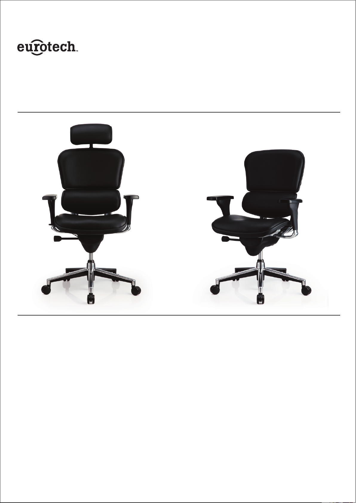
CHAIR NAME AND SKU OR MODEL
LE9ERG(N)/LE10ERGLO(N) /FE55ERG/FE66ERGLO
Remove
all items from the carton. Verify all components before assembly.
INSTRUCTIONS
NUMBER
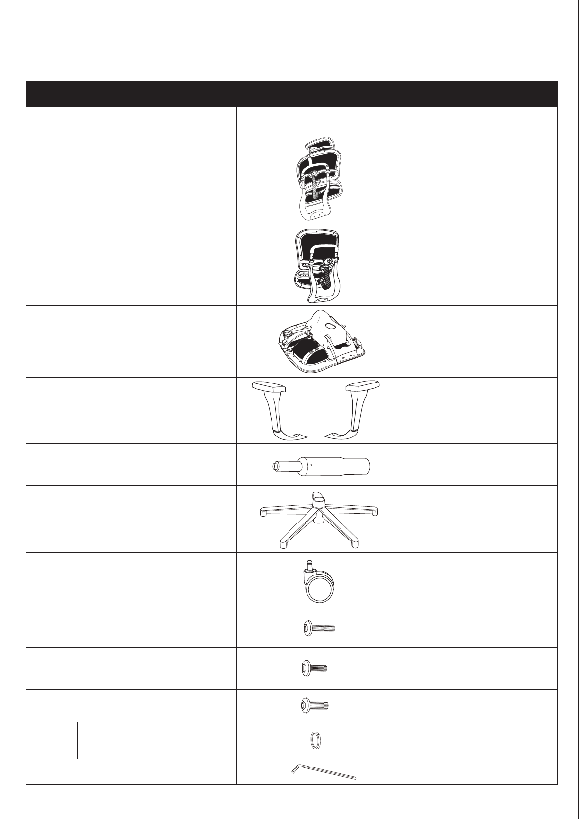
Part List
Key
1
A
B
C
D
Description
LE9ERG Backrest
LE10ERGLO Backrest
Seat
Armrests
(1 left & 1 right armrest)
Part
Qty.
1
1
1
2
Spare
E
F
G
H
I
J
K
Seat Post(Cylinder)
Star Base
Caster
Type A Arm Bolts
(1/4" x 1")
Type B Arm Bolts
(1/4" x 5/8")
Back Bolts
(M8 X 17mm)
Washers for Arm Bolts
( Ø6.5*10.5*1.5mm)
1
1
r
5
2
2
2
1
11
1
4 2
L
• Please tighten your chairs hardware every six months. • Please tighten your chairs hardware every six months. • Please tighten your chairs hardware every six months.
Allen Wrench
1
Page 3

ASSEMBLY INSTRUCTIONS
TYPE B
TYPE C
CHAIR NAME AND SKU OR MODEL NUMBER
LE9ERG(N)/LE10ERGLO(N)/FE55ERG/FE66ERGLO
Remove all items from the carton. Verify all components before assembly.
STEP 1
E
F
r
G
Press the Casters (G) into the holes at the end of each
leg of the Base (F).
Insert Seat Post (E) into the center hole of the base (F).
STEP 3
r
J
STEP 2
STEP 2
C
TYPE A
TYPE B
TYPE B
TYPE A
L
D
STEP 2
D
The Type B Arm Bolt is shorter and will be inserted into the
hole CLOSER to the mechanism. The Type A Arm Bolt is longer
and will be inserted into the hole FARTHER away from the
mechanism.
For easy assembly, place the Seat Cushion (C) face down on a
flat surface. Attach Armrest (D) to the Seat Cushion (C) as
shown using 1 Type A Arm Bolt (H) with 1 washer (K) and 1 Type
B Arm Bolt (I) with 1 washer (K) on each arm.
Tighten the bolts securely with the enclosed Allen Wrench (L).
STEP 4
C
TYPE B
J
L
J
Seat must slide into the slot on back.
A
Please be careful to use the correct Back Bolts (J).
Assemble the Backrest (A) to the Seat Cushion (C)
using 2 Back Bolts (J) .
Tighten the bolts securely with the enclosed Allen
Wrench (L).
PREVENTIVE MAINTENANCE AND WARNING!
• USE THIS PRODUCT ONLY FOR SEATING ONE PERSON AT A TIME.
• DO NOT USE THIS CHAIR AS A STEP STOOL / LADDER.
• DO NOT SIT ON ANY PART OF THE CHAIR EXCEPT THE SEAT.
• DO NOT USE CHAIR ON UNEVEN FLOOR SURFACES.
• DO NOT USE CHAIR UNLESS ALL BOLTS, SCREWS AND KNOBS ARE TIGHTENED.
• EVERY SIX MONTHS, PLEASE MAKE SURE ALL BOLTS, SCREWS AND KNOBS ARE
FULLY TIGHTENED TO ENSURE STABILITY.
r
r
Now turn the assembled seat upright and locate the
center hole of the Mechanism over the Seat Post.
Push down firmly until the connection is secure.
• IF ANY PARTS ARE MISSING, BROKEN, DAMAGED OR WORN, STOP USE OF THE
PRODUCT UNTIL REPAIRS ARE MADE USING FACTORY AUTHORIZED PARTS.
• DISPOSE OF PACKAGING PROPERLY. PLASTIC BAG IS NOT A TOY. DO NOT USE
PLASTIC BAG AS HEAD COVERING – IT MAY CAUSE SUFFOCATION.
• FAILURE TO FOLLOW THESE WARNINGS COULD RESULT IN SERIOUS INJURY.
• NOTE: SOME SCREWS MAY BE PREASSEMBLED. IF PREASSEMBLED, IGNORE
ASSEMBLY INSTRUCTIONS.
Page 4

OPERATING INSTRUCTIONS
CHAIR NAME AND SKU OR MODEL NUMBER
LE9ERG(N)/LE10ERGLO(N)/FE55ERG/FE66ERGLO
A1 HEADREST HEIGHT ADJUSTMENT
B1 B ACK REST TILT A NGLE ADJU STMEN T B2 B ACK REST TENSION A DJUST MENT
A2 HEADREST ANGLE ADJUSTMENT
A1 HEADREST HEIGHT ADJUSTMENT
While seated, hold headrest frame
and move up or down to adjust
height. There are 6 positions with
a 1.6” range of adjustment.
For LE9ERG only.
A2 H EA DREST ANGLE A DJ USTMENT
While seated, hold the headrest
cushion and turn to adjust the
angle. The Headrest has a 30º angle
adjustment.
For LE9ERG only.
B1 B ACKREST TILT ANGLE ADJUSTM EN T
While seated, pull the single rod control
lever completely backward and lean
against the back. When your desired
angle is achieved, return the lever to the
original middle position to lock your tilt
angle into place. There are 3 positions
that provide 25º of range.
B3 B ACK REST HEIGHT AD JUSTM ENT
B4 L UMBAR SUPP ORT HEI GHT ADJ UST MENT
B2 B ACKREST TENSION ADJUSTMENT
While seated, turn the Backrest Tilt
Tension Adjustment handle clockwise or
counterclockwise to adjust the tilt tension
to your preferred level of resistance.
B3 B ACKREST HEIGHT ADJUSTMENT
While seated, hold the sides of the
backrest handle and move up or down.
There is a 1.57” range of adjustment.
B4 L UMBAR SUPPO RT HEIGHT ADJ USTMENT
A. The height of the lumbar support can be
adjusted by lifting or lowering the backrest
height.
B. Suitable height of the lumbar support
provides optimum comfort.
Page 5

OPERATING INSTRUCTIONS
CHAIR NAME AND SKU OR MODEL NUMBER
LE9ERG(N)/LE10ERGLO(N)/FE55ERG/FE66ERGLO
C1 ARMREST HEIGHT ADJUSTMENT
C3 A RM PAD FORWARD A ND BACK WARD ADJUSTMENT
C2 A RM PAD ANGLE ADJU STMENT
C1 ARMREST HEIGHT ADJUSTMENT
While seated, grasp each armrest and
raise to your desired height. In order to
lower the arm, lift the armrest to its highest
position and it will go back down to the
lowest height. Then repeat to get to your
desired height. The arm height adjustment
range is 3.3”.
C2 ARM PAD ANGLE ADJUSTMENT
While seated, a 15º range of movement
can be achieved by swiveling the arm pads
inward or out ward.
C3 A RM P AD FORWARD AND BACKWARD
AD JU STMENT
While seated, push the arm pads
forward or backward to a desired position.
The range of movement is approximately 2”.
D1 S EAT HEIGHT A DJ USTME NT
D2 S EAT DEPTH AD JUSTM EN T
D1 S EAT HEIGHT ADJUSTMENT
While seated, pull the single rod control lever
upward and hold it while raising or lowering
the seat to reach your desired seat height.
When the lever is released to its original
position, the seat height is locked.
The seat height adjustment range is
approximately 3.6”.
D2 S EAT DEPTH ADJUSTMENT
While seated, push the single rod control
lever forward to adjust the seat depth.
The range of movement for the seat is
approximately 1.97". When your desired
seat position is achieved, return the lever
to the original middle position to lock your
seat position into place.
Page 6

OUR PROMISE.
They say with age comes wisdom. And while we’ve learned a lot since we sold
our first office chair in 1979, even then we knew that superior craftsmanship and
design are essential ingredients in delivering real value for our customers. All
these years later, those three simple pillars still stand behind our promise of
exceptional seating with every chair we sell.
DESIGN CRAFTSMANSHIP VALUE
Eurotech. Sit Smarter.
THE EUROTECH
• For all products except for 24/7 chairs (see below), Eurotech warrants to the original
purchaser all components for the life of the product with the exception of upholstery
and foam, which will be warranted for five years.
• For 24/7 chairs, Eurotech warrants to the original purchaser of all 24/7 chairs all components
for 10 years with the exception of upholstery and foam which will be warranted for 2 years.
• Eurotech warrants to the original purchaser that all parts will be free from material defects.
Eurotech will repair or replace, at its option, any unaltered components.
• Eurotech does not warrant any aftermarket hardware that is installed on the product.
• Eurotech’s warranty is limited to the normal use of the product in a forty hour work week
and a 250lb. weight limit unless otherwise noted.
• Eurotech shall NOT be liable for consequential or incidental damage arising from any
product defect.
WARRANTY
• Eurotech’s warranty is limited to replacement or repair and does not cover cost of
transportation and labor. There are no other warranties expressed or implied other than
those specifically described.
• Eurotech does not warrant customer’s own material.
This warranty is made as of 9/15/16. Please see http://www.eurotechseating.com/warranty-
information for any updates and/or revisions to this warranty.
 Loading...