

EuroLite LED Pixel Mesh User Manual
©
Copyright
Reproduction prohibited!
Keep this manual for future needs!
USER MANUAL
LED Pixel
Mesh

1
2
2
3
4
4
5
5
5
5
6
7
7
8
9
10
10
11
11
12
14
15
16
17
18
18
20
22
25
25
26
Warning.................................................................................…...……………..…………………………….………..….
Safety-instructions…………………………………………………………………………………………………………
Operating Determinations.……………………………………………………………………………………………..
Description...............................................................................…...………………………………………….………..…
Features and Overview ………………………………...….……………….………….……….……….………………
Overall Requirements……….…………………….……………………….……………………….……………………..…
Computer System Requirements……….……………………….……………………….………………………….……..
Set Up and Operation.....................................................................……..………………………………………………
LED Pixel Mesh Limitations ……………………………………………………………………….……...……….……..
Included with the Software Bundle………………………………………………………………………..…………..
Communication Wire Facture………………………………………………………………………………………….
Making an additional Net-cable………………………………………………………………………………………
How to connect the Pixel Mesh………………………………………………………………………………………..
IEC and Data Output Connections……………………………………………………………………………………
Screen Control System Instruction……………………………………………………………………………………..
PC Host Computer………………………………………………………………………………………………………..
System Connection Mode………………………………………………………………………………………………
System Connection Chart……………………………………………………………………………………………….
Mounting System to LED Screen Connection……………………………………………………………………….
Sender card………………………………………………………………………………………………………………..
Backside View……………………………………………………………………………………………………………..
Sender card Installation……………………………………………………………………………..…………………..
LED Vision Studio MX Control System Installation……………………………………………………………………
Display Card Settings…………………………………………………………………………………………………….
ATI Display Card Settings………………………………………………………………………………………………..
GEFORCE Display Card Settings……………………………………………………………………………………….
Receiver Card Configuration…………………………………………………………………………………………..
Maintenance...................................................................................………..………….…….……………………….…
Troubleshooting............................................................................………………….………………….………………...
Product Specifications.................................................................……………….…….………………………………..
2
WARNING
FOR YOUR OWN SAFETY, PLEASE READ THIS USER MANUAL CAREFULLY
BEFORE YOUR INITIAL START-UP!
SAFETY INSTRUCTIONS
Every person involved with the installation, operation and maintenance of this dev ice has to:
- be qualified
- follow the instructions of this manual
Before your initial start-up, please make sure that there is no damage caused by transportation. Should
there be any, consult your dealer and do not use the device.
To maintain perfect condition and to ensure a safe operation, it is absolutely necessary for the user to
follow the safety instructions and warning notes written in this manual.
Please consider that damages caused by manual modifications to the device are not subject to
warranty.
This device contains no user-serviceable parts. Refer servicing to qualified technicians only.
IMPORTANT:
The manufacturer will not accept liability for any resulting damages caused by the nonobservance of this manual or any unauthorized modification to the device.
Never let the power-cord come into contact with other cables! Handle the power-cord and all
connections with the mains with particular caution!
Never remove warning or informative labels from the unit.
Do not open the device and do not modify the device.
Do not connect this device to a dimmerpack.
Do not shake the device. Avoid brute force when installing or operating the device.
Do not switch the device on and off in short intervals.
Never use the device during thunderstorms, unplug the device immediately.
Only use device indoor, avoid contact with water or other liquids.
Avoid flames and do not put close to flammable liquids or gases.
Only operate the device after having familiarized with its functions.
Always disconnect power from the mains, when device is not used or before cleaning! Only
handle the power-cord by the plug. Never pull out the plug by tugging the power-cord.
Make sure that the device is not exposed to extreme heat, moisture or dust.
Make sure that the available voltage is not higher than stated on the rear panel.
Make sure that the power-cord is never crimped or damaged. Check the device and the power-
cord from time to time.
If the external cable is damaged, it has to be replaced by a qualified technician.
If device is dropped or struck, disconnect mains power supply immediately. Have a qualified
engineer inspect for safety before operating.
If the device has been exposed to drastic temperature fluctuation (e.g. after transportation), do
not switch it on immediately. The arising condensation water might damage your device. Leave
the device switched off until it has reached room temperature.
If your dev ic e f ail s to w ork properl y, d isc ontinue use immediatel y. Pac k the unit sec urel y
(pref erabl y in the orig inal pac k ing m aterial ), and return it to your dealer f or serv ic e.
CAUTION! Be careful with your operations.
With a dangerous voltage you can suffer
a dangerous electric shock when touching the wires!
3
The user is responsible for correct positioning and operating of the LED Pixel Mesh. The
manufacturer will not accept liability for damages caused by the misuse or incorrect installation
of this device.
This device falls under protection class I. Therefore it is essential to connect the yellow/green
conductor to earth.
Repairs, servicing and electric connection must be carried out by a qualified technician.
For repl acement use f uses of same type and rat ing onl y.
OPERATING DETERMINATIONS
This device is not designed for permanent operation. Consistent operation breaks will ensure that the
device will serve you for a long time without defects.
The maximum ambient temperature ta = 45°C must never be exceeded.
The relative humidity must not exceed 50 % with an ambient temperature of 45° C.
If this device is operated in any other way, than the one described in this manual, the product may suffer
damages and the warranty becomes void.
Any other operation may lead to dangers like short-circuit, burns, electric shock, lamp explosion, crash
etc.
You endanger your own safety and the safety of others!
Improper installation can cause serious damage to people and property !
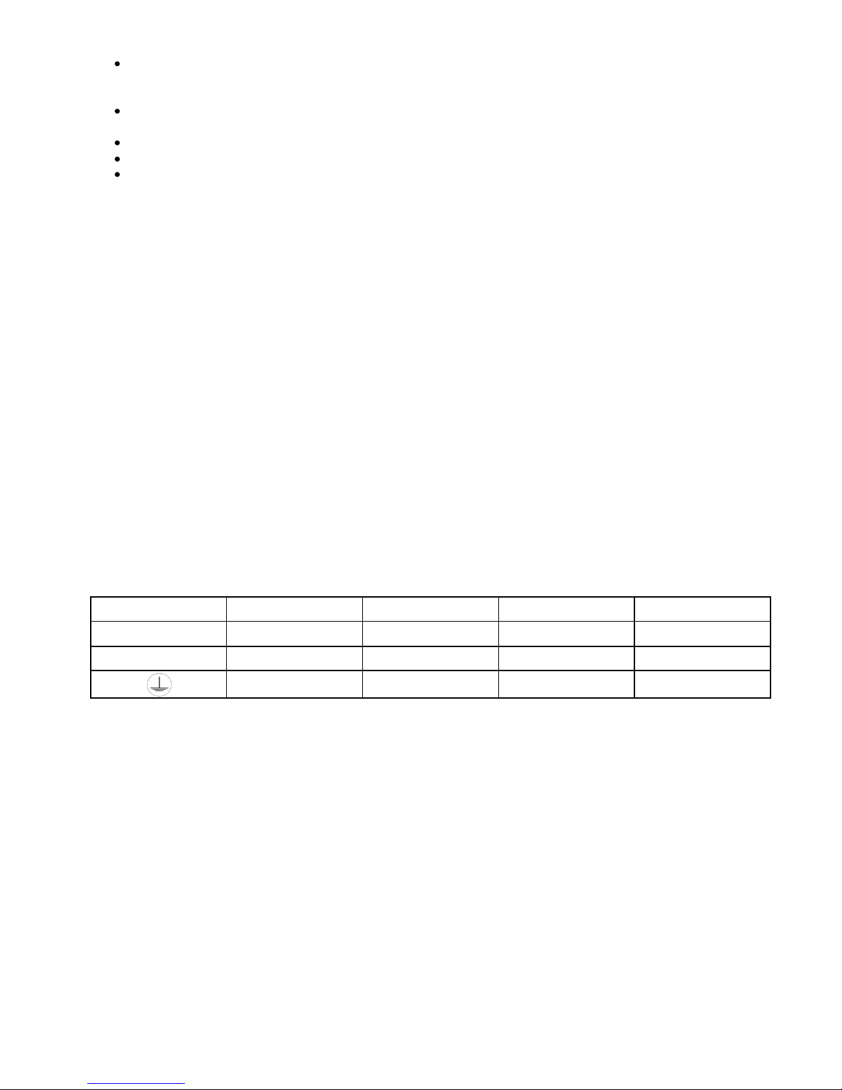
Connection with the mains
Connect the device to the mains with the power-plug.
Always pay attention, that the right color cable is connected to the right place.
International
EU Cable
UK Cable
US Cable
Pin
L
BROWN
RED
YELLOW/COPPER
FASE
N
BLUE
BLACK
SILVER
NUL
YELLOW/GREEN
GREEN
GREEN
EARTH
Make sure that the device is always connected properly to the earth!
Improper installation can cause serious damage to people and property !
4
Description of the device
Features
The LED Pixel Mesh is a f abul ous LED Lightef fec t
• Average Lifespan: 50,000~100,000hrs
• Mounting system has rigging points and flexible configurations
• Rated Power: 75W
• Cooling: Direct air convection
• LED/Pixel: 2xRED/1XGREEN/1XBLUE
• Module size: 640mm×640mm×65mm
• Pixel/Unit:16*16
• Pixel Pitch:40mm
• Pixel Density(dot/ m2):625
• Pixel composition:2R1G1B 4Φ5 oval LED
• Brightness(cd/ m2):1300
• Optimal viewing distance(m):60
• Module peak value power(≤W):75
• Module average power(≤W):40
• Module weight(kg):10
• Scanning mode:Static scan
• Viewing angle:120°(60°horizontally and vertically)
• Driven voltage(V):4.5~5.5
• Gray scale:256 levels respectively
• Frame change speed:≥60(frame/second)
• Control mode:In step with the computer monitor
• Blind spot rate:≤0.0002
• Operating voltage:AC220V±15% 47~64HZ
• Control distance(m):<130
• Temperature environment:-10℃~50℃
• Humidity environment:10%~90%RH
• Indoor use only
Control
• Software: LEDstudio 8
• System: Windows XP with video card (NOT included)
• Appl ications: Fixed installations, small or large, interior / advertising /stage
• Works with other manufacturer’s software: Arkaos or Sweetlight Timeline
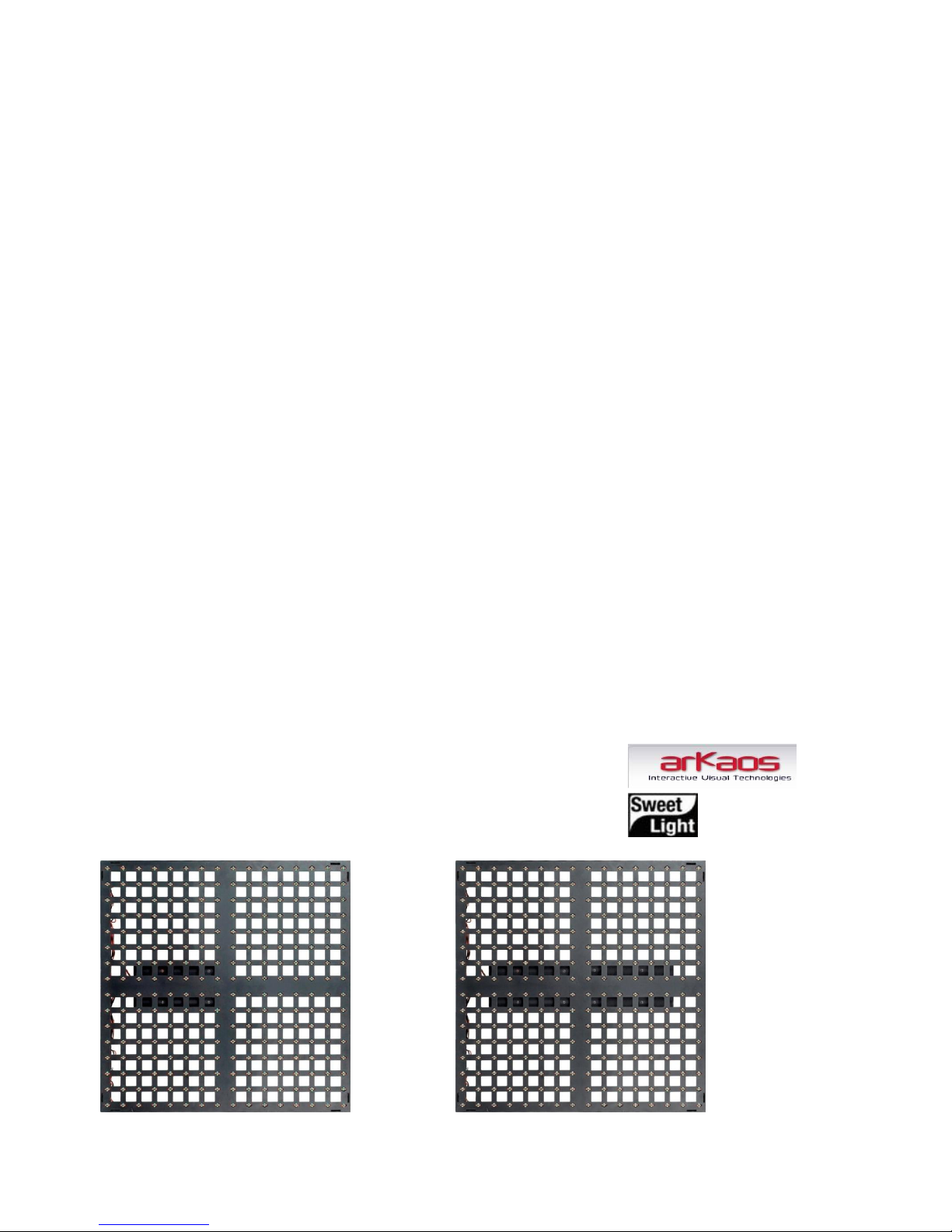
Overview
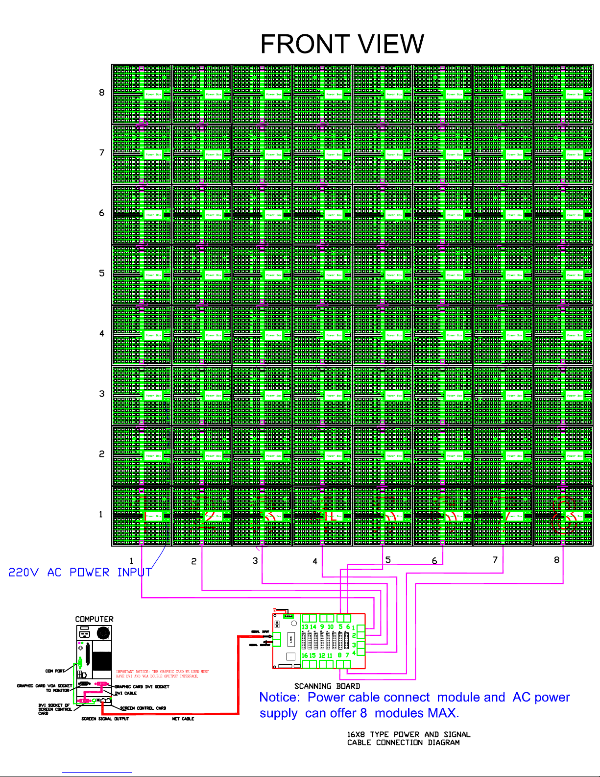
Fig. 1
Pixel Mesh (101150) Pixel Mesh Controller (101151)
5
Overall Requirements
• Windows XP computer with an available PCI slot
• Graphics card with 2x DVI or 1x VGA + 1x DVI
• LED Pixel Mesh Controll er; 1 controll er f or every 16 panel s w ide and 8 panel s high
Computer System Requirements
Minimum
Operating system: Windows XP SP2 (Service Pack 2)
Processor: Pentium 200 MHz with at least one free PCI slot
Harddisk: 20 GB 5400 RPM
Memory: 128 MB
Graphic Card: Graphics Card with dual display Mode and DVI output
Note: Only tested with ATI Graphic Card
Recommended
Operating system: Windows XP SP2 (Service Pack 2)
Processor: Pentium 1 GHz or better with at least one free PCI slot
Harddisk: 40 GB 7200 RPM or more
Memory: 512 MB or higher
Graphic Card: Graphics Card with dual display Mode and DVI output
Set Up and Operation
Before plugging the unit in, always make sure that the power supply matches the product specification
voltage. Do not attempt to operate a 120V specification product on 230V power, or vice versa.
Always disconnect from electric mains power supply before cleaning or servicing.
Damages caused by non-observance are not subject to warranty.
The LED Pixel Mesh can only be used indoors. The LED Pixel Mesh can be viewed during night-time as well
as day-time. Due to the clever mounting system it is easy to setup. The LED Pixel Mesh excellent design
allows you to vary the setup in many shapes and sizes.
LED Pixel Mesh Limitations
N ote: 1 LED Pixel Mesh Controll er for every 16 panel s w ide and 8 panel s high
Horizontal Panels (Left/Right)
Vertical Panels (UP/Down)
Resolution
1 Panel is 16 by 16 pixels on your PC screen.
So 8 x 6 panels (5,12 x 3,84 meters) = a resolution of 128 x 96 pixels in Windows XP.
Minimum 1 Panel
16 columns of LED clusters or 16 horizontal pixels/lines
Maximum with 8 panels (1 Controller)
128 columns of LED clusters or 128 horizontal pixels/lines
Minimum 1 Panel
16 rows of LED clusters or 16 vertical pixels/lines
Maximum with 16 panels (1 Controller)
256 rows of LED clusters or 256 vertical pixels/lines
Minimum 1 Panel
16 X 16 Pixels
Maximum With (1 Controller)
256 X 128 Pixels
6
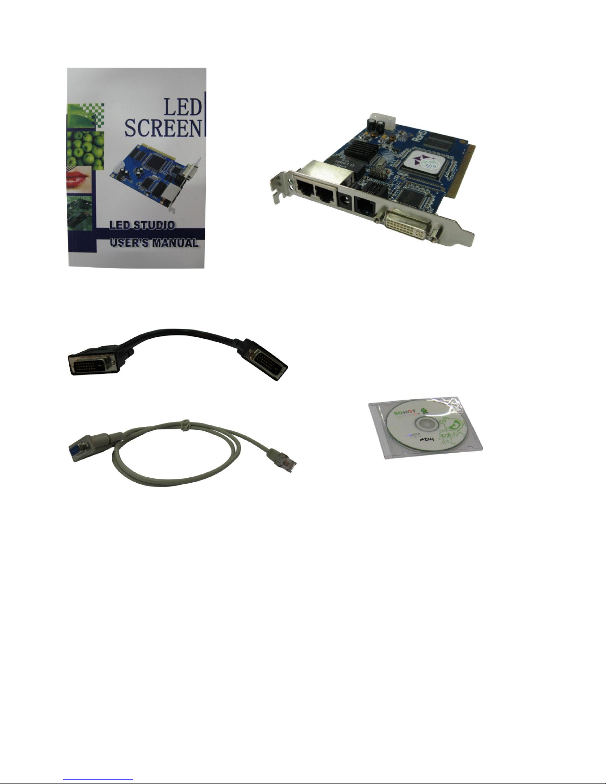
Included with the Software Bundle
User manual PC Sender Card
DVI cable (DVI to DVI)
Fig. 2
RS232 to RJ-11 cable CD with LED Studio 8
7
Communication Wire Facture
Cable from Computer to Scan Board 20m
1 2 3 4 5 6 7
8
INPUT
White/Orange
Orange
White/Green
Blue
White/Blue
Green
White/Brown
Brown
OUTPUT
White/Orange
Orange
White/Green
Blue
White/Blue
Green
White/Brown
Brown
Cable from Scan Board to Mesh Panel 3,5m
1 2 3 4 5 6 7
8
INPUT
White/Orange
Orange
White/Green
Blue
White/Blue
Green
White/Brown
Brown
OUTPUT
Brown
White/Brown
Green
White/Blue
Blue
White/Green
Orange
White/Orange
Cable between Mesh Panels
1 2 3 4 5 6 7
8
INPUT
White/Orange
Orange
White/Green
Blue
White/Blue
Green
White/Brown
Brown
OUTPUT
Blue
White/Brown
White/Blue
White/Orange
White/Green
Brown
Orange
Green
C-Side 1 8
A-Side B-Side B-Side
Fig. 3
D-Side
Making an additional cable from the computer to the Scan Board
A Standard NET CABLE cannot be used to replace the NET CABLE required to transmit the information for
the LED Pixel Mesh.
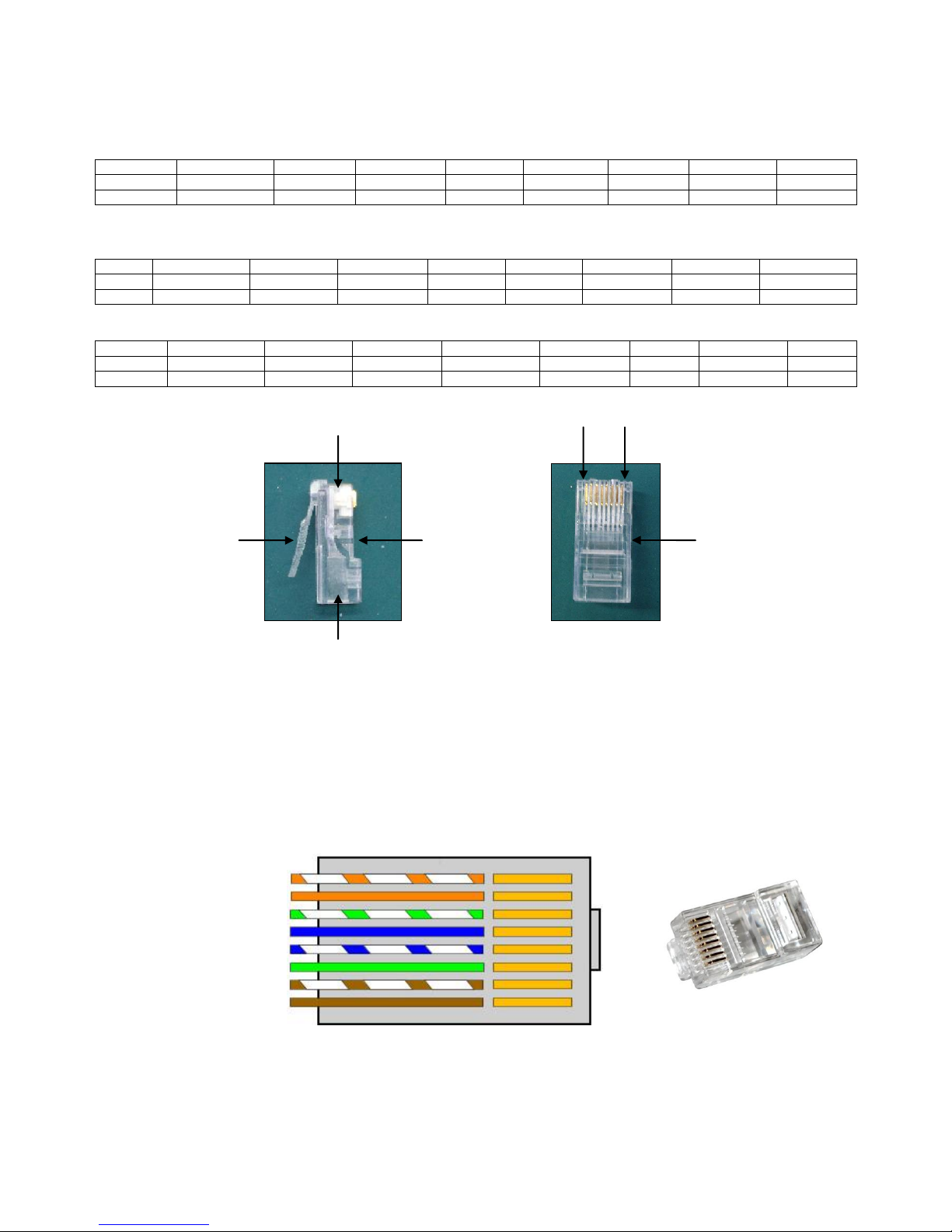
Please follow the following instructions in order to create extra NET CABLE.
Take a standard net cable (Cat5/ 5E /6) and connect it to the RJ-45 connector just like displayed on the
picture. The wires should now be colored as following:
1- white & orange
2- orange
3- white & green
4- blue
5- white & blue
6- green
7- white & brown
8- brown RJ-45 Connector
Insert each wire into an RJ-45 connector with the white & orange wire connected to PIN 1, the orange
wire connected to the second PIN, etc.
Both ends of the NET WIRE are connected in this way.
 Loading...