

Page 1

Page 2

2
• DE
INHALT
EINFÜHRUNG ..................................................... 3
Produktmerkmale ................................................... 3
Lieferumfang ........................................................... 3
WICHTIGE SICHERHEITSHINWEISE ................. 4
BEDIENELEMENTE UND ANSCHLÜSSE ........... 5
INBETRIEBNAHME ............................................. 6
Installation ............................................................... 6
DMX512-Anschluss ................................................. 6
Stromversorgung herstellen ................................... 6
Betriebsart wählen .................................................. 6
DMX-Ausfallmodus wählen ..................................... 7
REINIGUNG UND WARTUNG ............................. 7
TECHNISCHE DATEN ......................................... 7
Zubehör .................................................................. 7
D00119375, Version 1.0, Stand 27/09/2018
Produkt-Updates, Dokumentation, Software und Support
erhalten Sie unter www.eurolite.de. Die neueste Version
der Bedienungsanleitung finden Sie im Downloadbereich
des Produkts.
© 2018 Eurolite. Alle Rechte vorbehalten.
Dieses Dokument darf ohne schriftliche Genehmigung des
Copyrightinhabers weder ganz noch teilweise reproduziert
werden. Der Inhalt dieses Dokuments kann ohne vorherige
Ankündigung modifiziert werden, wenn Änderungen in
Methodik, Design oder Herstellung dies erforderlich
machen.
Alle in diesem Dokument erwähnten Marken gehören den
jeweiligen Eigentümern.
Page 3
3
• DE
Willkommen bei Eurolite! Schön, dass Sie sich für eines unserer Produkte
EINFÜHRUNG
Erleben Sie Eurolite.
Videos zum Produkt,
passendes Zubehör,
Dokumentation,
Firmware- und SoftwareUpdates, Support und
News zur Marke. Sie
finden all das und vieles
mehr auf unserer
Website. Besuchen Sie
uns auch auf unserem
YouTube-Kanal und
Facebook.
www.eurolite.de
www.youtube.com/
eurolitevideo
www.facebook.com/
Eurolitefans
entschieden haben. Eurolite bietet Ihnen Zugang zur Welt der Showtechnik mit
einer weltweit einzigartigen Vielfalt an Produkten sowohl für professionelle
Anwender als auch für Einsteiger.
Wenn Sie nachfolgende Hinweise beachten, sind wir sicher, dass Sie über viele
Jahre Freude an Ihrem Kauf haben werden. Diese Bedienungsanleitung zeigt
Ihnen, wie Sie Ihr neues Produkt von Eurolite installieren, in Betrieb nehmen
und nutzen.
Damit Sie sich und andere keinen Gefahren aussetzen, beachten Sie bitte
unbedingt alle Sicherheitshinweise und verwenden das Produkt nur wie in
dieser Anleitung beschrieben. Bitte bewahren Sie diese Bedienungsanleitung
für weiteren Gebrauch auf und geben Sie sie ggf. an nachfolgende Besitzer
weiter.
Produktmerkmale
• DMX-Verteiler für die Aufteilung eines DMX-Eingangssignals auf 4 DMX-
Ausgänge
• Anschlüsse: 2 x DMX-Eingang (parallel), 2 x DMX-Durchschleifausgang
(parallel), 4 x DMX-Ausgang
• Eingang und Durchschleifausgang sind auf Vorder- und Rückseite doppelt
ausgeführt und parallel geschaltet
• Unterstützt RDM für die bidirektionale Kommunikation über die DMX-Leitung
• Schaltbarer Filtermodus zum Herausfiltern der RDM-Daten verhindert
Probleme bei Betrieb mit Geräten ohne RDM-Unterstützung
• Bypass-Funktion für die problemlose Verarbeitung von nonkonformen DMX-
Signalen
• Ausgangsfrequenz im Filtermodus wählbar: 22/44 Hz
• DMX-Ausfallmodus wählbar: Hold, Blackout, Null
• Zuschaltbarer Abschlusswiderstand
• Eingang und Ausgänge XLR 3-polig (Neutrik)
• Ausgänge galvanisch getrennt
• Jeder DMX-Ausgang mit unabhängigem Treiber und Statusanzeige
• Jeder DMX-Ausgang kann wieder mit bis zu 32 DMX-Geräten verbunden
werden
• Spannungsversorgung über mitgeliefertes Steckernetzteil
• Rackmontage über separat erhältliche Blende (Artikel 70064872)
Lieferumfang
• DMX-Splitter
• Netzteil
• diese Bedienungsanleitung
Page 4
4
• DE
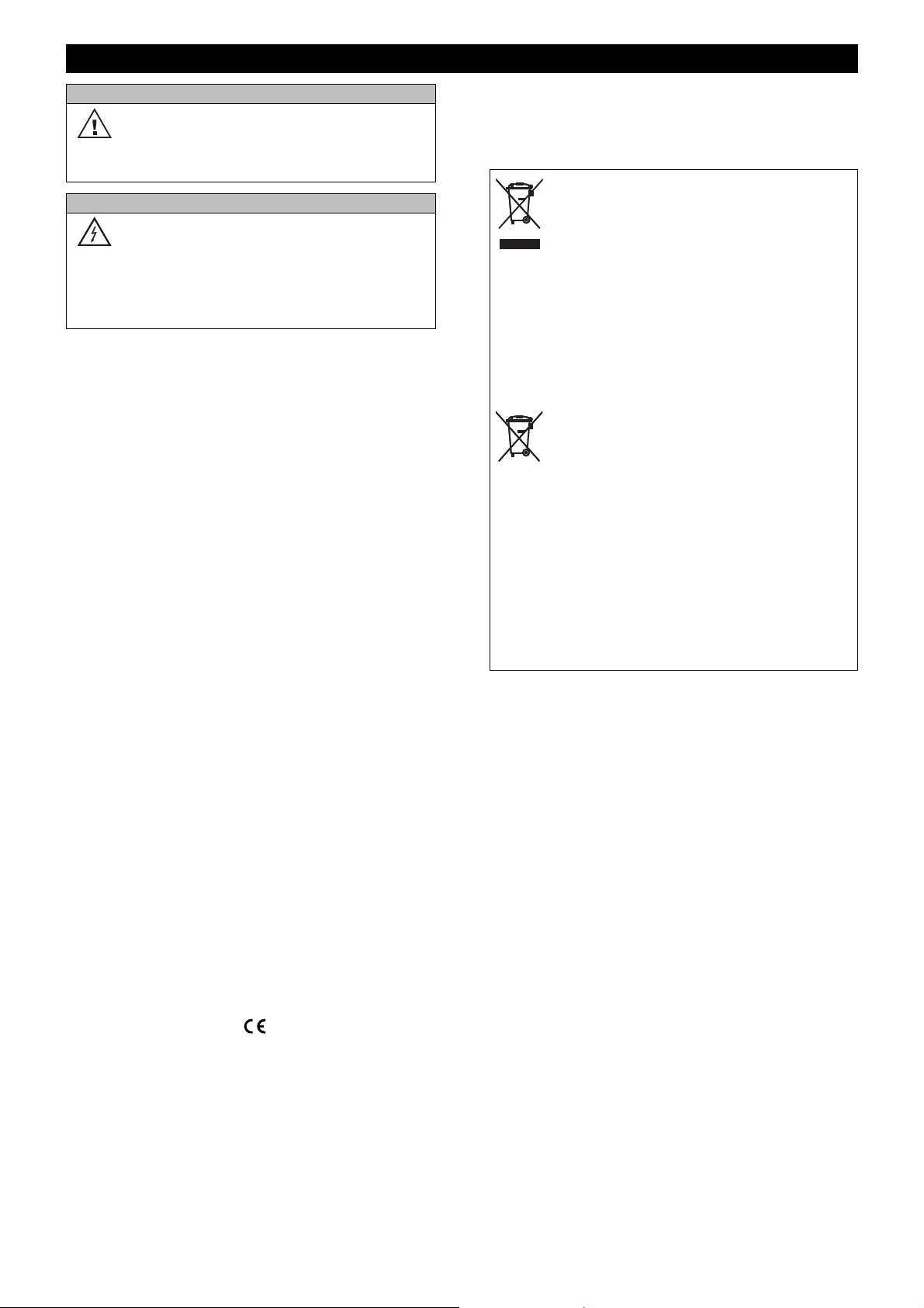
ACHTUNG
!
GEFAHR
!
WICHTIGE SICHERHEITSHINWEISE
Betriebsbedingungen
Das Gerät ist für die Benutzung in
Innenräumen ausgelegt. Schützen Sie es
• Bitte lesen Sie vor der Verwendung des Produkts
diese Bedienungsanleitung. Sie enthält wichtige
Hinweise für den korrekten Betrieb. Bewahren Sie
diese Anleitung für weiteren Gebrauch auf.
• Verwenden Sie das Produkt ausschließlich gemäß
den hier gegebenen Vorgaben. Bei Schäden, die
durch Nichtbeachten dieser Bedienungsanleitung
verursacht werden, erlischt der Garantieanspruch.
Für Folgeschäden wird keine Haftung
übernommen.
• Bei Sach- oder Personenschäden, die durch
unsachgemäße Handhabung oder Nichtbeachten
der Sicherheitshinweise verursacht werden,
übernehmen wir keine Haftung und es erlischt
jeder Garantieanspruch.
• Aus Sicherheitsgründen ist das eigenmächtige
Umbauen oder Verändern des Produkts ist nicht
gestattet und hat den Verfall der Garantieleistung
zur Folge.
Niemals irgendeinen Teil des Produkts öffnen, um
Stromschläge zu vermeiden.
• WICHTIG: Dieses Produkt ist nicht für die
Benutzung im Freien geeignet! Nur für den
Innenbereich! Nicht in der Nähe von Wasser
verwenden! Der ideale Temperaturbereich liegt bei
-5 bis +45 °C.
• Vor der Reinigung den Netzstecker aus der
Steckdose ziehen. Zur Reinigung nur ein weiches
Tuch und niemals Lösungsmittel verwenden.
• Niemals das Netzkabel und den -stecker mit
nassen Händen berühren, da die Gefahr eines
Stromschlags besteht.
• Das Produkt ist kein Spielzeug. Halten Sie es vor
Kindern und Haustieren fern. Lassen Sie
Verpackungsmaterial nicht achtlos liegen.
• Das Gerät erfüllt allen erforderlichen Richtlinien der
EU und ist deshalb mit gekennzeichnet.
Bestimmungsgemäße Verwendung
Der Splitter dient zur Verteilung bzw.
Signalverstärkung von DMX512-Steuersignalen in
Lichtanlagen. Das Gerät verfügt über einen DMXEingang und vier DMX-Ausgänge sowie einen DMXDurchschleifausgang für den Anschluss eines
weiteren Splitters. Alle Ein- und Ausgänge sind als 3polige XLR-Anschlüsse ausgeführt. Der Splitter
vor Feuchtigkeit und Nässe.
Elektrischer Schlag durch Kurzschluss
Seien Sie besonders vorsichtig beim
Umgang mit gefährlicher Netzspannung.
Bei dieser Spannung können Sie einen
lebensgefährlichen elektrischen Schlag
erhalten.
unterstützt RDM für die bidirektionale
Kommunikation über die DMX-Leitung.
Informationen zur Entsorgung
Bitte übergeben Sie das Gerät bzw. die
Geräte am Ende der Nutzungsdauer zur
umweltgerechten Entsorgung einem
örtlichen Recyclingbetrieb. Geräte, die mit
diesem Symbol gekennzeichnet sind,
dürfen nicht im Hausmüll entsorgt
werden. Für weitere Informationen
wenden Sie sich bitte an Ihren Händler
oder die zuständige örtliche Behörde.
Entnehmen Sie evtl. eingelegte Batterien
und entsorgen Sie diese getrennt vom
Produkt.
Als Endverbraucher sind Sie durch die
Batterieverordnung gesetzlich zur
Rückgabe aller gebrauchten Batterien
und Akkus verpflichtet. Die Entsorgung
über den Hausmüll ist verboten.
Verbrauchte Batterien können Sie
unentgeltlich bei den Sammelstellen Ihrer
Gemeinde und überall, wo Batterien
verkauft werden, abgeben. Mit der
Verwertung von Altgeräten und der
ordnungsgemäßen Entsorgung von
Batterien und Akkus leisten Sie einen
wichtigen Beitrag zum Schutz unserer
Umwelt.
Page 5
5
• DE
BEDIENELEMENTE UND ANSCHLÜSSE
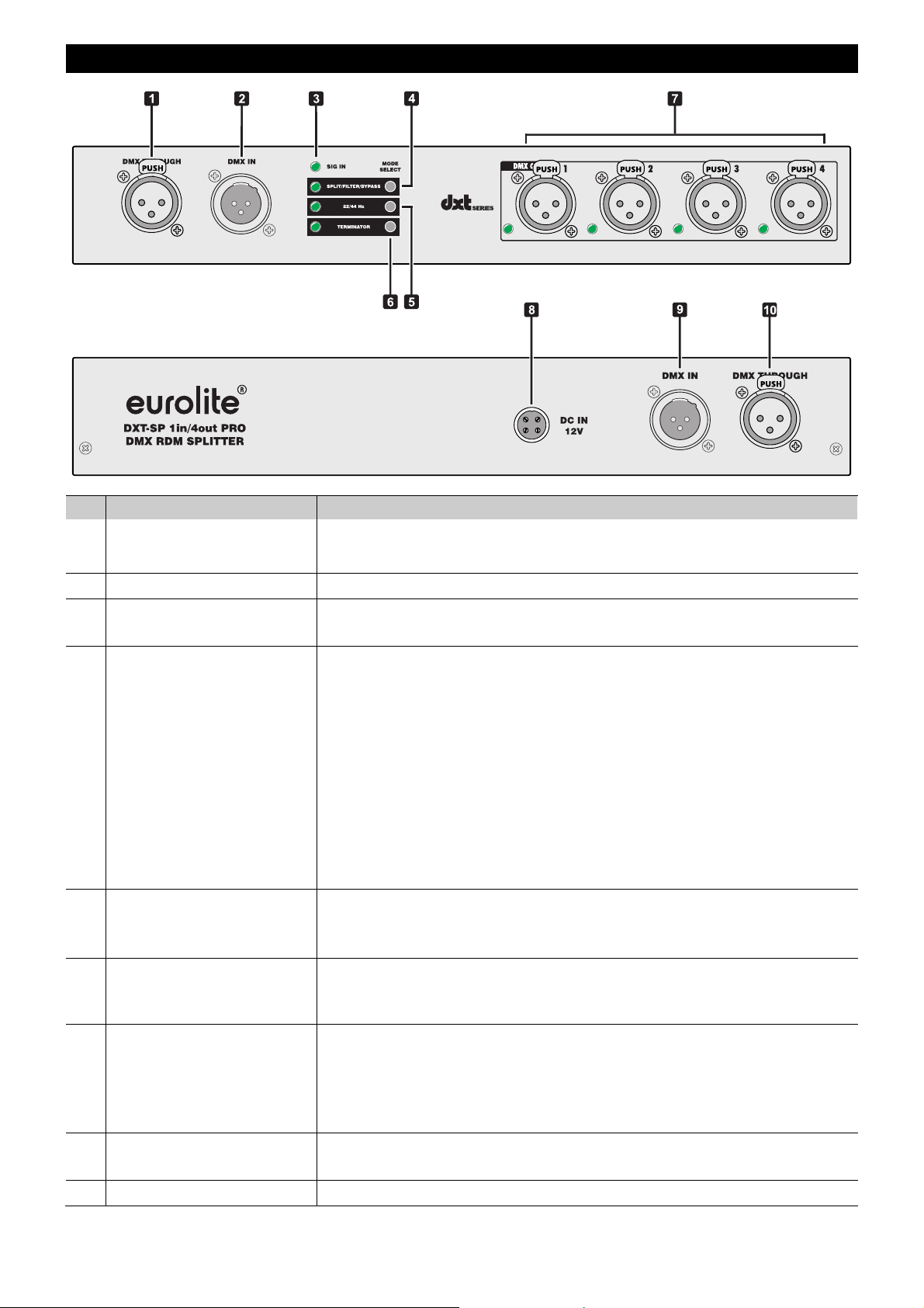
Nr. Element Funktion
1 DMX512-
Durchschleifausgang
Direkter DMX-Ausgang zum Anschluss weiterer DMX-Geräte oder DMXSplitter in derselben DMX-Kette wie der DMX-Eingang.
2 DMX512-Eingang 3-poliger XLR-Stecker zum Anschluss des DMX-Steuersignals.
3 Signalanzeige SIG IN
4 Umschalter SPLIT/FILTER/
BYPASS mit LED
• Blinkt grün: DMX-Signal vorhanden
• Leuchtet rot: kein DMX-Signal vorhanden oder Signal fehlerhaft
Zum Einstellen der Betriebsart kurz drücken.
• LED leuchtet grün: Splitterbetrieb mit RDM-Funktion ohne DMXSignalaufbereitung
• LED leuchtet gelb: Filterbetrieb mit DMX-Signalaufbereitung
• LED leuchtet rot: Bypassbetrieb ohne Signalbearbeitung
Zum Einstellen und Bestätigen des DMX-Ausfallmodus 3 Sekunden
drücken. Mit dem Umschalter 22/44 Hz den Modus wählen.
• LED leuchtet grün: der letzte gültige DMX-Wert wird gehalten und auf
allen Ausgängen ausgegeben
• LED leuchtet rot: keine DMX-Ausgabe
• LED leuchtet orange: auf allen DMX-Kanälen wird der Wert 0 ausgegeben
5 Umschalter 22/44 Hz mit
LED
Zum Einstellen der DMX-Ausgabefrequenz im Filterbetrieb.
• LED leuchtet rot: 22 Hz
• LED leuchtet grün: 44 Hz
6 Umschalter TERMINATOR
mit LED
7 DMX512-Ausgänge 1 - 4
mit LED
• LED leuchtet grün: Die DMX-Leitung des DMX-Eingangs wird mit einem
Widerstand abgeschlossen
• LED leuchtet nicht: Der Abschlusswiderstand ist nicht aktiv.
3-polige XLR-Buchse zum Anschluss weiterer DMX-Ketten.
• LED leuchtet grün: Ausgabe eines DMX-Signals
• Einzelne LED leuchtet rot: Kurzschluss in angesteckter Leitung oder
Ausgabemodul defekt
• Alle LEDs leuchten rot: keine Signalausgabe
8 Netzanschluss
Stecken Sie hier die Anschlussleitung des Netzteils ein und fixieren Sie sie
mit der Überwurfmutter.
9 DMX512-Eingang Rückseitiger Anschluss alternativ zur Frontplatte (2).
Page 6
6
• DE
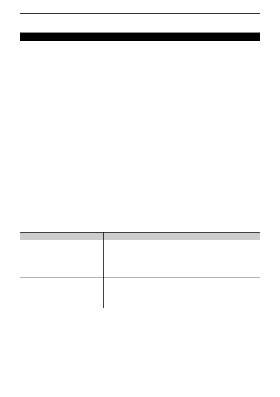
10 DMX512-
Durchschleifausgang
Rückseitiger Anschluss alternativ zur Frontplatte (1).
INBETRIEBNAHME
Installation
Stellen Sie das Gerät auf eine ebene Fläche oder bauen Sie es mit der als Zubehör erhältlichen Blende in ein 19"Rack ein. Verschrauben Sie dazu die Blende unten und oben am Gehäuse. Bei Racks sollten sich sowohl die
Vorder- als auch die Rückseite öffnen lassen. Das Rackgehäuse sollte mit einem Lüfter versehen sein. Achten Sie
bei der Standortwahl des Gerätes darauf, dass die warme Luft aus dem Rack entweichen kann und genügend
Abstand zu anderen Geräten vorhanden ist. Dauerhafte Überhitzung kann zu Schäden an dem Gerät führen. Sie
können das Gerät mit vier Schrauben M6 im Rack befestigen.
DMX512-Anschluss
Zum Anschluss sollten spezielle DMX-Kabel für hohen Datenfluss verwendet werden.
1 Geben Sie das DMX-Steuersignal auf einen der XLR-Eingänge DMX IN. Die XLR-Eingänge auf der Vor- und
Rückseite sind parallel geschaltet. Um Fehlfunktionen zu vermeiden, verwenden Sie bitte ausschließlich
entweder den DMX-Eingang auf der Vorderseite oder den DMX-Eingang auf der Rückseite.
2 An die DMX-Ausgänge DMX OUT kann jeweils eine DMX-Kette geschlossen werden, die wiederum aus jeweils
maximal 32 DMX-Geräten bestehen kann. Am letzten Gerät jeder DMX-Kette muss die DMX-Leitung durch
einen Abschlusswiderstand (120 Ω) abgeschlossen werden.
3 Soll der Splitter selbst eine DMX-Kette abschließen, drücken Sie den Umschalter TERMINATOR. Es wird dann
ein Abschlusswiderstand zugeschaltet.
4 Am DMX-Durchschleifausgang DMX THROUGH können Sie einen weiteren DMX-Splitter oder eine weitere
DMX-Kette aus maximal 32 DMX-Geräten anschließen. Die Durchschleifausgänge auf der Vor- und Rückseite
sind parallel geschaltet. Um Fehlfunktionen zu vermeiden, verwenden Sie bitte ausschließlich entweder die
Buchse auf der Vorderseite oder die Buchse auf der Rückseite.
Stromversorgung herstellen
Schließen Sie das beiliegende Netzteil an die Anschlussbuchse am Gerät an und stecken Sie es in eine
Steckdose. Das Gerät ist damit eingeschaltet. Zum Ausschalten und nach dem Gebrauch den Netzstecker wieder
trennen, um unnötigen Stromverbrauch zu vermeiden.
Betriebsart wählen
Drücken Sie kurz die Taste SPLIT/FILTER/BYPASS zum Einstellen der Betriebsart. Die LED daneben zeigt die
aktuelle Einstellung an.
Betriebsart LED Bedeutung
Splitter Grün
Filter Orange
Bypass Rot
Der DMX-Splitter überträgt RDM-Daten zwischen den angeschlossenen
Geräten in beide Richtungen.
Die RDM-Daten werden aus der DMX-Leitung herausgefiltert. Wählen
Sie diese Betriebsart für Geräte ohne RDM-Unterstützung, da diese
sonst unter Umständen flickern oder andere unterwünschte Reaktionen
zeigen.
Der interne Prozessor ist deaktiviert und das Eingangssignal gelangt
unverändert auf die Ausgänge. Falls RDM-Daten am Eingang vorhanden
sind, werden diese mit ausgegeben. Da jedoch der Prozessor nicht
aktiv ist, werden keine RDM-Daten von den angeschlossenen Geräten
zurück übertragen.
Page 7
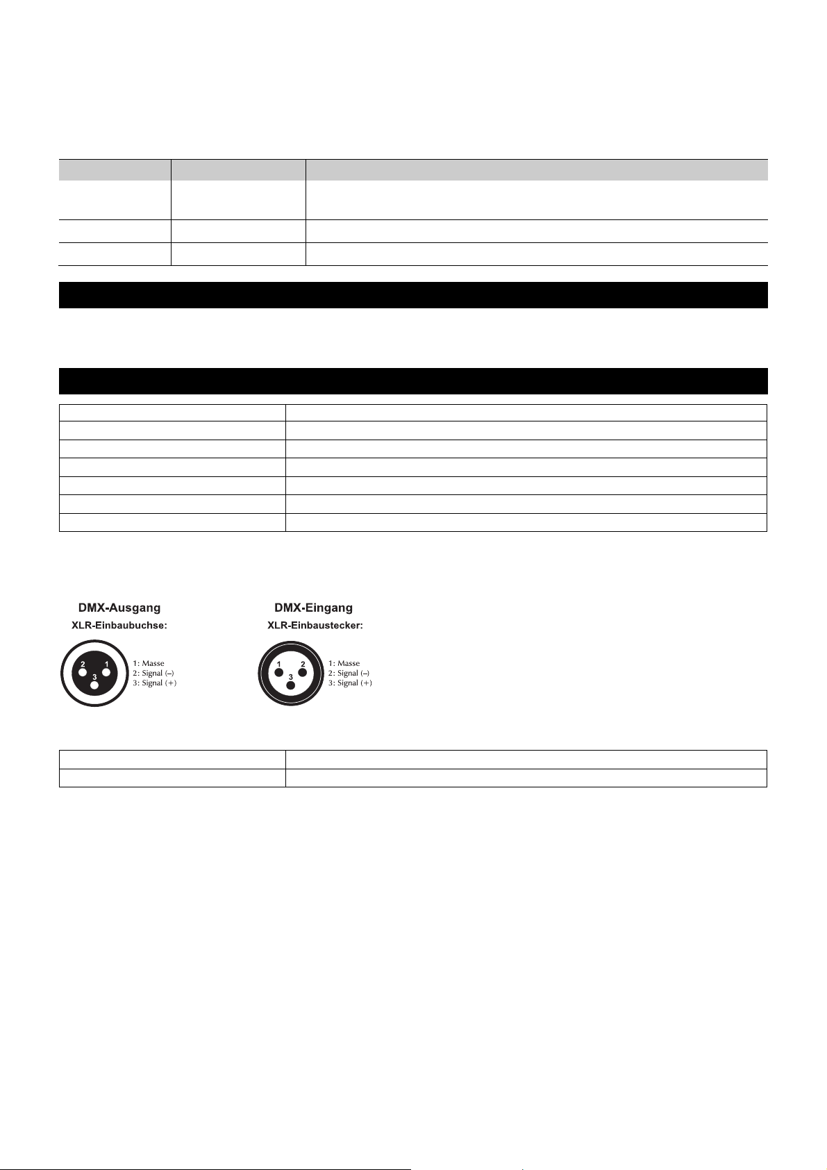
7
• DE
Spannungsversorgung:
100-240 V AC, 50/60 Hz
über mitgeliefertes Netzteil (
12 V/1 A)
Gesamtanschlusswert:
3,6 W
DMX512
-
Eingang:
2
x 3-pol XLR
-
Einbaustecker (Neutrik)
DMX
-
Durchschleifausgang:
2
x 3-pol XLR
-
Einbau
buchse
(Neutrik)
DMX512
-
Ausgang:
4
x 3-pol XLR
-
Einbaubuchse
(Neutrik)
Maße (L x B x
H): 275 x 100 x 41 mm
Gewicht:
1,1 kg
Best.
-
Nr. 70064872
EUROLITE Montagerahmen für DXT Serie
Best.
-
Nr. 70064873
EUROLITE Blindplatte für DXT Montagerahmen
DMX-Ausfallmodus wählen
Um festzulegen, wie sich das Gerät verhält, wenn kein DMX-Eingangssignal anliegt, halten Sie die Taste
SPLIT/FILTER/BYPASS 3 Sekunden gedrückt. Der Einstellmodus wird aktiviert und die zugehörige LED blinkt
abwechselnd grün und rot. Wählen Sie nun den gewünschten Modus mit der Taste 22/44 Hz. Die LED daneben
zeigt die aktuelle Einstellung an. Drücken Sie nach Ihrer Einstellung kurz die Taste SPLIT/FILTER/BYPASS, um
den Einstellmodus zu verlassen.
Modus LED Bedeutung
Hold Grün
Der letzte gültige DMX-Wert wird gehalten und auf allen Ausgängen
ausgegeben.
Null Rot Keine DMX-Ausgabe, solange kein DMX-Eingangssignal anliegt.
Blackout Orange
Auf allen DMX-Kanälen wird der Wert 0 ausgegeben.
Das Produkt ist bis auf eine gelegentliche Reinigung für Sie wartungsfrei. Zur Reinigung können Sie ein
fusselfreies, angefeuchtetes Tuch verwenden. Überlassen Sie Reparaturen einem Fachmann.
TECHNISCHE DATEN
Technische Daten können im Zuge der Weiterentwicklung des Produkts ohne vorherige Ankündigung geändert werden.
Steckerbelegung:
REINIGUNG UND WARTUNG
Zubehör
Page 8

8
• EN
CONTENTS
INTRODUCTION .................................................. 9
Product features ..................................................... 9
What is included ..................................................... 9
IMPORTANT SAFETY INSTRUCTIONS .............. 10
OPERATING ELEMENTS AND CONNECTIONS . 11
SETUP ................................................................. 12
Installation ............................................................... 12
DMX512 connection ............................................... 12
Connection to the power supply ............................ 12
CLEANING AND MAINTENANCE ....................... 13
TECHNICAL SPECIFICATIONS .......................... 13
Accessories............................................................. 13
D00119375, version 1.0, publ. 27/09/2018
For product updates, documentation, software and
support please visit www.eurolite.de. You can find the
latest version of this user manual in the product’s
download section.
© 2018 Eurolite. All rights reserved.
No part of this document may be reproduced in any form
without the written permission of the copyright
owner. The contents of this document are subject to
revision without notice due to continued progress in
methodology, design, and manufacturing. Eurolite shall
have no liability for any error or damage of any
kind resulting from the use of this document.
All trademarks mentioned herein are the property of their
respective owners.
Page 9
9
• EN
W
elcome to Eurolite! Thank you for choosing one of our products.
Eurolite is
INTRODUCTION
Experience Eurolite.
Product videos, suitable
accessories, firmware
and software updates,
documentation and the
latest news about the
brand. You will find this
and much more on our
website. You are also
welcome to visit our
YouTube channel and
find us on Facebook.
www.eurolite.de
www.youtube.com/
eurolitevideo
www.facebook.com/
Eurolitefans
your connection to the world of show with an unparalleled variety of products,
both for professionals and beginners.
If you follow the instructions given in this manual, we are sure that you will
enjoy this product for a long period of time. This user manual will show you
how to install, set up and operate your new Eurolite product.
Users of this product are recommended to carefully read all warnings in order
to protect yourself and others from damage. Please keep this manual for future
needs and pass it on to further owners.
Product features
• DMX splitter for splitting one DMX input signal to 4 DMX outputs
• Connections: 2 x DMX input (parallel), 2 x DMX feed-through output
(parallel), 4 x DMX output
• Input and feed-through output are duplicated on the front and rear panel
and connected in parallel
• Supports RDM for bidirectional communication over the DMX line
• Switchable filter mode allows all RDM data to be filtered out in order to
prevent problems when using fixtures intolerant of RDM
• Bypass function to process non-DMX signals
• Output frequency in filter mode adjustable: 22/44 Hz
• DMX fail mode selectable: hold, blackout, null
• Switchable termination resistor
• Input and outputs XLR 3-pin (Neutrik)
• Input and outputs galvanically isolated
• Each DMX output with independent driver and status indicator
• Each DMX output can be connected to 32 DMX devices
• Powered via included PSU
• Rack installation via optional rack mounting kit (item 70064872)
What is included
• DMX splitter
• Power adapter
• This user manual
Page 10
10
• EN
CAUTION
!
DANGER
!
IMPORTANT SAFETY INSTRUCTIONS
Operating conditions
This device has been designed for indoor
use only. Keep this device away from rain
• Please read these operating instructions carefully
before using the product. They contain important
information for the correct use of your product.
Please keep them for future reference.
• Only use the product according to the instructions
given herein. Damages due to failure to follow
these operating instructions will void the warranty!
We do not assume any liability for any resulting
damage.
• We do not assume any liability for material and
personal damage caused by improper use or noncompliance with the safety instructions. In such
cases, the warranty/guarantee will be null and void.
• Unauthorized rebuilds or modifications of the
product are not permitted for reasons of safety and
render the warranty invalid.
• Never open any part of the product to prevent a
possible electric shock.
• IMPORTANT: This product is not an outdoor
product! Only for indoor use! Do not use this
device near water. The recommended temperature
range is -5 to +45 °C.
• To clean the unit, disconnect it from the power
source.
• Only use a soft cloth, never use any solvent.
• Do not touch the power cord and connectors with
wet hands as it may cause electric shock.
• This product is not a toy. Keep it out of the reach of
children and pets. Do not leave packaging material
lying around carelessly.
• This unit corresponds to all required directives of
the EU and is therefore marked with .
Intended use
The DXT-SP 1in/4out PRO DMX RDM Splitter is
designed for splitting or amplifying DMX512 control
signals in lighting installations. The unit features one
DMX input and four DMX outputs as well as two
input feed-through terminals for connection to an
additional splitter. All inputs and outputs are
designed as 3-pin XLR connectors. The splitter
supports RDM for bidirectional communication over
the DMX line.
and moisture.
Electric shock caused by short-circuit
Be careful with your operations. With a
dangerous voltage you can suffer a
dangerous electric shock when touching
the wires!
Disposal of old equipment
When to be definitively put out of
operation, take the product to a local
recycling plant for a disposal which is not
harmful to the environment. Devices
marked with this symbol must not be
disposed of as household waste. Contact
your retailer or local authorities for more
information. Remove any inserted
batteries and dispose of them separately
from the product.
You as the end user are required by law
(Battery Ordinance) to return all used
batteries/rechargeable batteries. Disposing
of them in the household waste is
prohibited. You may return your used
batteries free of charge to collection
points in your municipality and anywhere
where batteries/rechargeable batteries
are sold. By disposing of used devices
and batteries correctly, you contribute to
the protection of the environment.
Page 11
11
• EN
OPERATING ELEMENTS AND CONNECTIONS
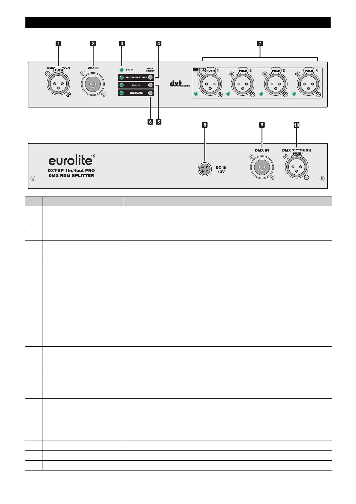
No. Element Function
1 DMX512 feed-through
output
Direct DMX output for connecting additional DMX devices or DMX splitters
within the same DMX chain as the DMX input.
2 DMX512 input 3-pin XLR plug to connect the DMX control signal.
3 SIG IN indicator • Flashes green: Incoming DMX input signal
• Lights red: No incoming DMX input signal or faulty DMX signal
4 SPLIT/FILTER/
BYPASS switch with LED
Shortly press this button to adjust the operating mode.
• LED lights green: Splitter mode with RDM function without DMX refresh
• LED lights yellow: Filter mode with DMX refresh
• LED lights red: Bypass mode without DMX refresh
Keep this button pressed for 3 seconds to adjust and confirm the DMX
failure mode. Select the mode with the switch 22/44 Hz.
• LED lights green: The most recent valid DMX value is held and output
through all DMX outputs
• LED lights red: No DMX output when there is no DMX input signal
• LED lights orange: The value 0 is output on all DMX channels
5 22/44 Hz switch with LED To adjust the DMX output frequency in filter mode.
• LED lights red: DMX output at 22 Hz
• LED lights green: DMX output at 44 Hz
6 TERMINATOR selector
switch with LED
• LED lights green: The DMX line of the DMX input is terminated by a
resistor.
• LED off: The terminating resistor is not active.
7 DMX512 outputs 1 – 4
with LED
3-pin XLR jack to connect DMX chains.
• LED lights green: DMX output active
• Single LED lights red: Short circuit in connected line or output module
defective
• All LEDs light red: No signal output
8 Power input To plug in the power plug of the supplied PSU. Fasten it with the swivel nut.
9 DMX512 input Rear connection as an alterative to the front panel (2).
10
DMX512 feed-through output Rear connection as an alterative to the front panel (1).
Page 12
12
• EN
SETUP
Installation
Set up the unit on a plane surface or mount it in a 19" rack with the optional mounting blade. Use four screws to
fasten the mounting blade to the top and bottom of the housing. The rack should be provided with doors on the
front and rear panel and a cooling fan. When mounting the device into the rack, please make sure that there is
enough space around the device so that the heated air can be passed on. Steady overheating will damage your
device. You can fix the device with four screws M6 in the rack.
DMX512 connection
For connection, use special DMX cables for high data flow.
1 Feed the DMX control signal to the XLR input DMX IN. The XLR inputs on the front and rear panel are
connected in parallel. To avoid malfunctions, use exclusively either the DMX input on the front, or the DMX
input on the rear panel.
2 Each of the unit's DMX outputs allows connection of one DMX chain, which in turn may consist of a maximum
of 32 DMX devices. At the last fixture in the DMX chain, the DMX line has to be terminated by a resistor (120
Ω).
3 If the DMX splitter should terminate a DMX chain, press the TERMINATOR selector switch. Then a termination
resistor is connected.
4 You can connect an additional DMX splitter or DMX chain with up to 32 DMX devices to the DMX feed-through
output DMX THROUGH. The feed-through outputs on the front and rear panel are connected in parallel. To
avoid malfunctions, use exclusively either the connector on the front, or the connector on the rear panel.
Connection to the power supply
Connect the power adapter provided to the corresponding input on the splitter and to a mains socket. Thus the
device is powered on. To switch off the device and after the operation, disconnect the mains plug of the power
adapter from the socket, to prevent unnecessary power consumption.
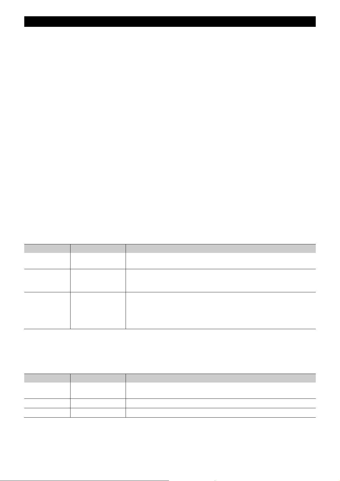
Select operating mode
Shortly press the button SPLIT/FILTER/BYPASS to adjust the operating mode. The respective LED indicates the
current selection.
Mode LED Description
Splitter Green
Filter Orange
Bypass Red
Select DMX failure mode
Keep the button SPLIT/FILTER/BYPASS pressed for 3 seconds to determine how the splitter behaves in case of
no incoming DMX input signal. Configuration mode is now activated and the respective LED flashes green and
red. You can now select the desired mode using the button 22/44 Hz. The LED next to the button indicates the
current setting. Shortly press the button SPLIT/FILTER/BYPASS to exit configuration mode.
Mode LED Description
Hold Green
Null Red No DMX output when there is no DMX input signal.
Blackout Orange
The DMX splitter transmits RDM data between the connected devices in
both directions.
RDM data is filtered from the DMX line. Select this mode when operating
devices which do not support RDM to avoid flickering or other undesired
effects.
The internal processor is deactivated and the incoming signal is
transmitted to the output sockets unchanged. If RDM data is received at
the DMX input socket, this data will be output too. As the processor is
inactive, however, no RDM data is transmitted back from the devices
connected to the output sockets of the splitter.
The most recent valid DMX value is held and output through all DMX
outputs.
The value 0 is output on all DMX channels.
Page 13
13
• EN
Power supply:
100-240 V AC, 50/60 Hz
via included power
adapter (
12 V/1 A)
Power consumption:
3.6 W
DMX512 input:
2
x 3-pin XLR plug (Neutrik)
DMX feed
-
through output:
2
x 3-pin XLR connector (Neutrik)
DMX512 output:
4
x 3-pin XLR connector (Neutrik)
Dimensions (L x W x H):
275 x 100 x 41 mm
Weight:
1.1 kg
No. 70064872
EUROLITE Mounting frame for DXT serie
s
No. 70064873
EUROLITE Blind plate for DXT mounting plate
CLEANING AND MAINTENANCE
The product is maintenance-free, except for occasional cleaning. You can use a lint-free, slightly dampened cloth
for cleaning. Refer all servicing to qualified personnel.
TECHNICAL SPECIFICATIONS
Specifications are subject to change without notice due to product improvements.
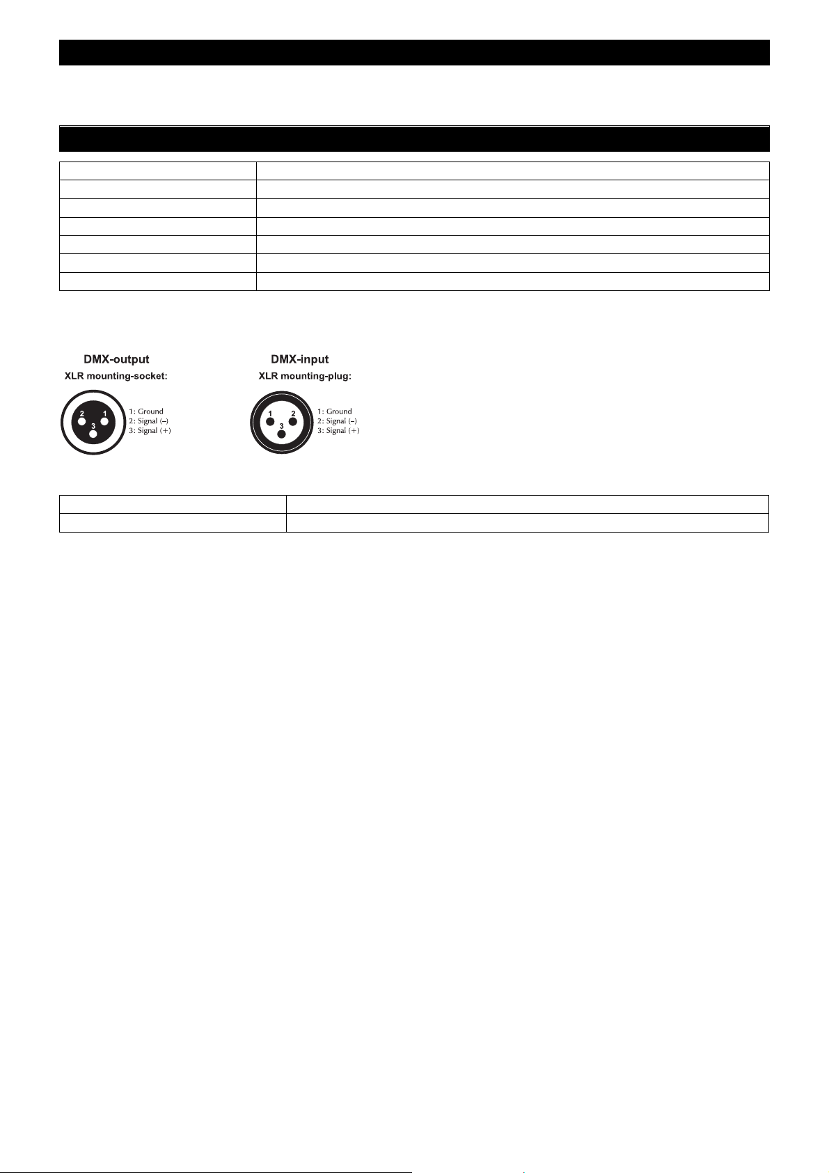
Pin connection:
Accessories
Page 14

14
• EN
Page 15

15
• EN
Page 16
Eurolite is a brand of Steinigke Showtechnic GmbH Andreas
-
Bauer
-
Str. 5 97297 Waldbüttelbrunn Germany
D00119375 Version 1.0 Publ. 27/09/2018
 Loading...