

Euro Appliances Milan EIF90ANT Instruction Manual
INSTRUCTION MANUAL

Thank you for choosing our product. From now on, cooking will always be pleasantly
creative with your new cooker.
We recommend carefully reading all the instructions in this manual, which includes
detailed information about the most suitable conditions for using the cooker correctly
and safely. These instructions also help you to become familiar with each component.
Useful advice is given for using recipients, utensils, positions of guides and control
settings.
The correct cleaning operations contained in this manual allow you to maintain the
cooker's performance unchanged over time.
The individual sections are set out in order to allow you to become familiar with all the
functions in the cooker. The text is easy to comprehend and is accompanied with
detailed images and simple pictograms.
Reading this manual thoroughly will provide you with the answer to any question that
may arise regarding the correct use of your new cooker.
INSTRUCTIONS FOR THE INSTALLER: for the qualified technician who is in
charge of adequately checking the gas system, installing, commissioning and testing
the appliance.
INSTRUCTIONS FOR THE USER: include suggestions, the description of the
controls and the correct cleaning and maintenance operations for the appliance.

Contents
3
1. General information ______________________________________ 5
1.1 Technical service __________________________________________________________ 5
2. Warnings for safety and use ________________________________ 6
3. Installation______________________________________________ 8
3.1 General warnings__________________________________________________________ 9
3.2 Replacing the adjustable feet ________________________________________________ 9
3.3 Fitting the front moulding ___________________________________________________ 10
3.4 Fitting the backguard (only available on certain models) __________________________ 10
3.5 Electric connection________________________________________________________ 11
3.6 Ventilation in rooms with gas appliances ______________________________________ 14
3.7 Gas connection __________________________________________________________ 15
3.8 Gas adjustments _________________________________________________________ 18
3.9 Connecting to LPG _______________________________________________________ 18
4. Final operations ________________________________________ 20
4.1 Levelling the cooker to the floor______________________________________________ 20
5. Description of controls ___________________________________ 21
5.1 The front panel___________________________________________________________ 21
6. Using the cooking hob ___________________________________ 27
6.1 Switching on the burners ___________________________________________________ 27
6.2 Switching off the burners ___________________________________________________ 27
6.3 Abnormal Operation ______________________________________________________ 27
7. Using the induction hob __________________________________ 28
7.1 General warnings_________________________________________________________ 28
7.2 Automatic radiant power distribution __________________________________________ 29
7.3 Energy regulator table _____________________________________________________ 30
7.4 Switching on the induction hob for the first time _________________________________ 30
7.5 Pan recognition __________________________________________________________ 31
7.6 Switching on a radiant element ______________________________________________ 32
7.7 Automatic switch-off ______________________________________________________ 34
7.8 Switching off manually _____________________________________________________ 34
7.9 Child safety _____________________________________________________________ 34
7.10 In the event of faults and failures_____________________________________________ 35
8. Using the ovens ________________________________________ 36
8.1 General warnings_________________________________________________________ 36
8.2 Storage drawer (only available on certain models) _______________________________ 36
8.3 Risk of condensation ______________________________________________________ 36
8.4 Using the electric multifunction oven __________________________________________ 37
8.5 Using the auxiliary oven with natural convection_________________________________ 39
9. Cooking suggestions ____________________________________ 40
9.1 Suggestions for using the hob burners correctly _________________________________ 40
9.2 Suggestions for using the induction hob correctly________________________________ 40
9.3 Suggestions for using the oven correctly ______________________________________ 40
Contents
4
10. Cleaning and maintenance _______________________________ 43
10.1 Cleaning stainless steel surfaces ____________________________________________ 43
10.2 Cleaning enamelled surfaces _______________________________________________ 43
10.3 Cleaning the polished surfaces ______________________________________________ 43
10.4 Cleaning the knobs and the control panel ______________________________________ 43
10.5 Cleaning the grids and burners ______________________________________________ 43
10.6 Cleaning the igniter plugs and thermocouples __________________________________ 44
10.7 Cleaning the induction hob _________________________________________________ 44
10.8 Cleaning the oven ________________________________________________________ 45
10.9 Replacing the oven light bulb _______________________________________________ 45
11. Special maintenance____________________________________ 46
11.1 Removing the oven door ___________________________________________________ 46
11.2 Removing the side rack-holder frames ________________________________________ 47
11.3 Removing and cleaning the inside oven fan ____________________________________ 48
Warnings
5
This user’s manual is an integral part of the product purchased. The user must conserve the manual
correctly so that it is always available for consultation during the use and maintenance of the
product. Keep this user’s manual for future reference. If the product is resold, the manual must be
transferred to any subsequent owner or user of the product.
The manufacturer is not liable for any inaccuracies in this booklet resulting from printing or
transcription errors. The manufacturer reserves the right to modify its products as it considers
necessary or in the interests of the user, without compromising their essential safety and operating
characteristics.
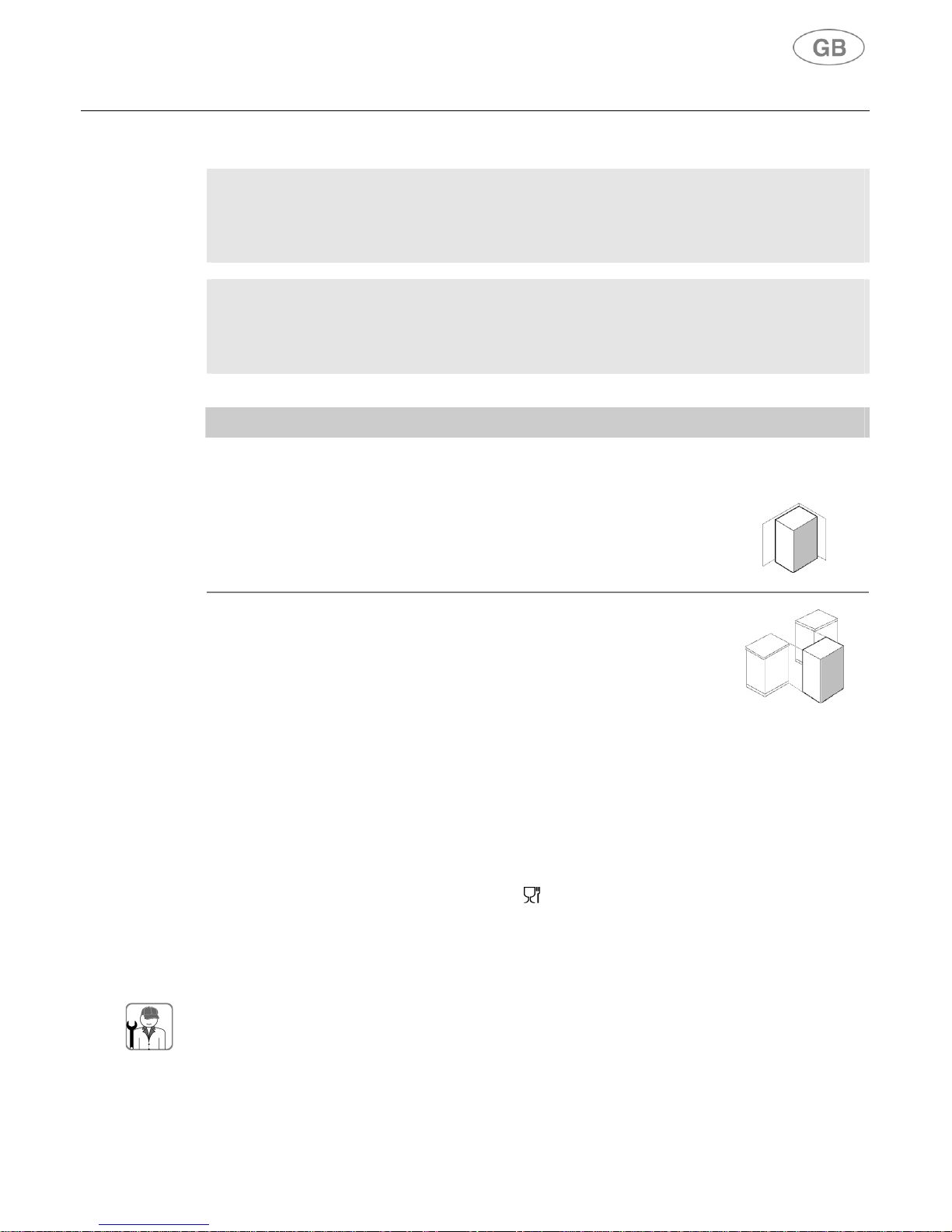
CLASSES OF APPLIANCES
The cooking appliances described in this operating manual belong to the following installation
classes:
• Class 1: non-flush-mounted cooking appliance;
• Class 2 – subclass 1: cooking appliance flush-mounted between two
units, made up of a single unit, but which can also be installed so that the
side walls are accessible.
1. General information
This product was manufactured in compliance with the following directives:
• 2006/95/EC relating to electrical equipment designed for use within certain voltage limits.
• 2004/108/EC relating to electromagnetic compatibility. In compliance with the provisions
relating to electromagnetic compatibility, the electromagnetic induction hob belongs to group 2
and to class b (EN 55011).
• 2009/142/EC for "Gas Appliances".
• EC Regulation no. 1935 of 27/10/2004 on materials and articles intended to come into
contact with food.
• 2011/65/EC (RoHS) on restricting the use of hazardous substances in manufacturing materials.
1.1 Technical service
Before leaving the factory, this appliance has been tested and set up by qualified, specialist
personnel, so as to guarantee the best operating results. Each repair or adjustment that may
subsequently be necessary must be carried out with the utmost care and attention. We therefore
recommend always contacting the Dealer where the appliance was purchased or your nearest
Service Centre, specifying the type of problem and the appliance model.
Warnings
6
2. Warnings for safety and use
THIS MANUAL IS AN INTEGRAL PART OF THE APPLIANCE. IT SHOULD BE KEPT IN GOOD CONDITION AND CLOSE
TO THE APPLIANCE FOR THE WHOLE LIFECYCLE OF THE COOKER. WE RECOMMEND READING THIS MANUAL
VERY CAREFULLY BEFORE USING THE COOKER. IN CASE AN ADDITIONAL JETS KIT IS GIVEN AS ACCESSORY
TO THE COOKER, WE RECOMMEND KEEPING AND PRESERVING IT. THE INSTALLATION MUST BE CARRIED OUT
BY QUALIFIED PERSONNEL AND IN COMPLIANCE WITH CURRENT STANDARDS. THIS APPLIANCE IS FOR
DOMESTIC USE AND CONFORMS TO THE EEC DIRECTIVES CURRENTLY IN FORCE. USE IN A PROFESSIONAL
SETTING AND INSTALLATION WITHIN A BUSINESS SUCH AS RESTAURANT, BAR, COMPANY CANTEEN OR ANY
OTHER USE OTHER THAN THAT SPECIFIED HERE WILL IMMEDIATELY VOID THE WARRANTY. THE APPLIANCE IS
BUILT FOR CARRYING OUT THE FOLLOWING FUNCTION: COOKING AND HEATING FOOD; ANY OTHER USE IS TO
BE CONSIDERED IMPROPER. THE MANUFACTURER DECLINES ANY RESPONSIBILITY SHOULD THE APPLIANCE
BE USED FOR PURPOSES OTHER THAN THOSE INDICATED.
THIS MANUAL IS AN INTEGRAL PART OF THE APPLIANCE. IT SHOULD BE KEPT IN GOOD CONDITION AND CLOSE
TO THE APPLIANCE FOR THE WHOLE LIFECYCLE OF THE COOKER. WE RECOMMEND READING THIS MANUAL
AND ALL THE INDICATIONS IT INCLUDES VERY CAREFULLY BEFORE USING THE COOKER. IN CASE AN
ADDITIONAL JETS KIT IS GIVEN AS ACCESSORY TO THE COOKER, WE RECOMMEND KEEPING AND
PRESERVING IT. THE INSTALLATION MUST BE CARRIED OUT BY AUTHORISED PERSON AND IN COMPLIANCE
WITH CURRENT REGULATIONS IN FORCE. THIS APPLIANCE IS ENVISAGED FOR DOMESTIC USE AND
CONFORMS TO THE AUSTRALIAN STANDARDS CURRENTLY IN FORCE. USE IN A PROFESSIONAL SETTING AND
INSTALLATION WITHIN A BUSINESS SUCH AS RESTAURANT, BAR, COMPANY CANTEEN OR ANY OTHER USE
OTHER THAN THAT SPECIFIED HERE WILL IMMEDIATELY VOID THE WARRANTY. THE APPLIANCE IS BUILT FOR
CARRYING OUT THE FOLLOWING FUNCTION: COOKING AND HEATING FOOD; ANY OTHER USE IS TO BE
CONSIDERED IMPROPER. THE MANUFACTURER DECLINES ANY RESPONSIBILITY SHOULD THE APPLIANCE BE
USED FOR PURPOSES OTHER THAN THOSE INDICATED.
AT THE MOMENT OF PURCHASE, THE USER ASSUMES DIRECT RESPONSIBILITY FOR THE PRODUCT AND MUST
THEREFORE MAKE SURE THAT, WITH NORMAL USE, NO INSTABILITY, DEFORMATION, BREAKAGE OR WEAR
OCCURS OVER TIME THAT WOULD REDUCE PRODUCT SAFETY.
THIS PRODUCT IS DESIGNED AND MANUFACTURED TO OPERATE SAFELY AND DOES NOT POSE ANY DANGERS
TO PEOPLE, ANIMALS, AND OBJECTS.
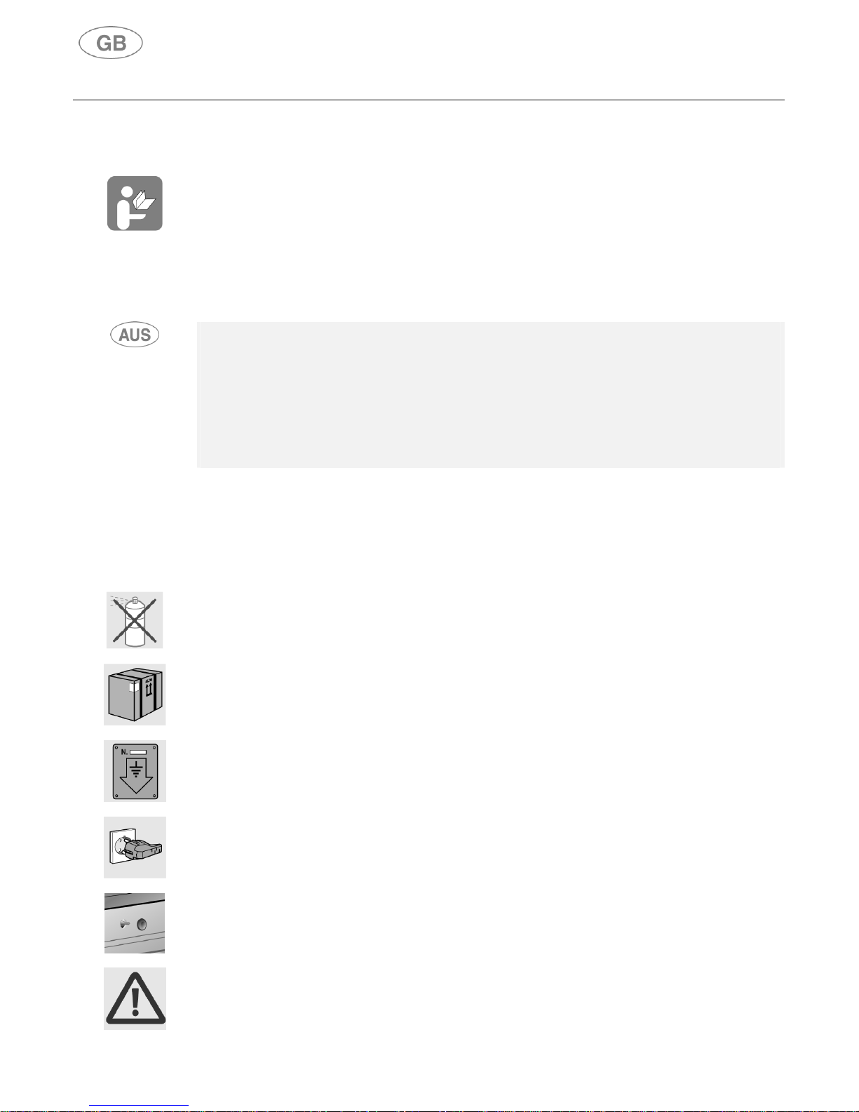
DO NOT MODIFY THIS APPLIANCE.
DO NOT SPRAY AEROSOLS IN THE VICINITY OF THIS APPLIANCE WHILE IT IS IN OPERATION.
WHERE THIS APPLIANCE IS INSTALLED IN MARINE CRAFT OR IN CARAVANS, IT SHALL NOT BE USED AS A
SPACE HEATER.
DO NOT LEAVE ANY PIECES OF THE PACKING UNATTENDED IN THE HOME. SEPARATE THE VARIOUS PACKING
MATERIALS AND DELIVER THEM TO THE NEAREST RECYCLING CENTRE.
THE EARTH CONNECTION IS OBLIGATORY CONFORMING TO THE MODALITIES ENVISAGED BY THE SAFETY
STANDARDS OF THE ELECTRICAL WIRING SYSTEM.
THE PLUG TO BE CONNECTED TO THE POWER SUPPLY CABLE AND THE RELATIVE SOCKET MUST BE THE
SAME TYPE AND MUST COMPLY WITH CURRENT STANDARDS. AFTER INSTALLING THE APPLIANCE MAKE SURE
THAT THE PLUG IS ACCESSIBLE TO ALLOW THE PERIODICAL CHECK-UP.
DO NOT PULL OUT THE PLUG BY PULLING THE CABLE.
SHOULD THE GAS TAPS BE DIFFICULT TO ROTATE, LUBRICATE THEM USING A SPECIFIC PRODUCT FOR HIGH
TEMPERATURES. CONTACT THE TECHNICAL SERVICE FOR THIS OPERATION.
IMMEDIATELY AFTER INSTALLATION, TEST THE APPLIANCE BRIEFLY BY FOLLOWING THE INSTRUCTIONS
SHOWN BELOW. IN THE EVENT OF A MALFUNCTION, DISCONNECT THE APPLIANCE FROM THE MAINS AND
CONTACT YOUR NEAREST TECHNICAL SERVICE CENTRE.
DO NOT ATTEMPT TO REPAIR THE APPLIANCE.
Warnings
7
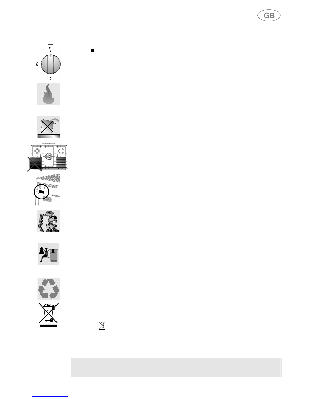
EACH TIME YOU FINISH USING THE COOKING HOB, ALWAYS CHECK THAT THE CONTROL KNOBS ARE IN "ZERO"
POSITION (OFF).
NEVER PUT INFLAMMABLE OBJECTS INTO THE OVEN: SHOULD IT BE ACCIDENTALLY SWITCHED ON, A FIRE
MAY BREAK OUT. IN THE EVENT OF A FIRE: CLOSE THE MAIN GAS SUPPLY AND CUT OFF THE ELECTRIC
CURRENT. DO NOT THROW WATER ON BURNING OR FRYING OIL. DO NOT STORE INFLAMMABLE OBJECTS OR
AEROSOL CANS NEAR THE APPLIANCE AND DO NOT SPRAY NEAR THE BURNERS WHEN SWITCHED ON. DO
NOT WEAR BAGGY CLOTHES OR ACCESSORIES THAT ARE NOT CLOSE TO THE BODY WHEN THE BURNERS
ARE SWITCHED ON: SERIOUS INJURIES CAN BE CAUSED BY BURNING FABRIC. DO NOT USE OR STORE
FLAMMABLE MATERIALS IN THE APPLIANCE STORAGE DRAWER OR NEAR THIS APPLIANCE.
DO NOT REST SAUCEPANS THAT DO NOT HAVE A PERFECTLY SMOOTH, EVEN BASE ON THE COOKING HOB.
DO NOT USE RECIPIENTS OR STEAK GRILLS THAT EXCEED THE OUTER PERIMETER OF THE COOKING HOB.
THE IDENTIFICATION PLATE WITH THE TECHNICAL DATA, SERIAL NUMBER AND THE MARK IS CLEARLY VISIBLE
ON THE BACK OF THE APPLIANCE.
A SECOND PLATE, INCLUDING DETAILED INFORMATION ABOUT THE MODEL AND SERIAL NUMBER, IS PLACED
INSIDE THE EQUIPMENT ON THE LEFT SIDE AND IS VISIBLE ON OPENING THE OVEN DOOR.
THESE PLATES MUST NEVER BE REMOVED.
THE APPLIANCE SHOULD ONLY BE USED BY ADULTS. DO NOT ALLOW CHILDREN TO APPROACH OR PLAY
WITH THE APPLIANCE. NEVER STORE ITEMS THAT CHILDREN MAY ATTEMPT TO REACH ABOVE THE
APPLIANCE. THE HEATING UP OF SOME PARTS OF THE APPLIANCE AND OF THE USED PANS MAY BE A
DANGER, SO DURING FUNCTIONING AND DURING ALL THE TIME NECESSARY FOR THE COOOLING DOWN, TAKE
CARE TO POSITION THE HOT PANS IN A WAY TO PREVENT BURNS OR OVERTURNING. AVOID LEAVING THE
OVEN DOOR OPEN DURING FUNCTIONING OR IMMEDIATELY SOON AFTER THE SWITCHING OFF. AVOID
TOUCHING THE HEATING ELEMENTS INSIDE THE OVEN AND GRILLS AS WELL.
RESTING OR SITTING ON THE OPEN OVEN DOOR, DRAWERS OR STORAGE COMPARTMENT CAN OVERTURN
THE APPLIANCE, AND CONSEQUENTLY CAUSE HARM. THE DRAWERS HAVE A DYNAMIC CAPACITY OF 25 KG.
IF THE COOKER IS SET ON A PEDESTAL, APPROPRIATE MEASURES MUST BE TAKEN TO PREVENT IT FROM
SLIDING OFF THE PEDESTAL.
WHEN THE APPLIANCE IS DECOMMISSIONED, IT MUST BE DISPOSED OF IN A SUITABLE RECYCLING CENTRE.
CUT OFF THE MAINS POWER CORD AFTER UNPLUGGING IT FROM THE WALL OUTLET, AND MAKE SAFE ANY
COMPONENTS WHICH MIGHT BE DANGEROUS FOR CHILDREN (DOORS, ETC.).
THIS APPLIANCE IS MARKED ACCORDING TO THE EUROPEAN DIRECTIVE 2002/96/EC ON WASTE ELECTRICAL
AND ELECTRONIC EQUIPMENT (WEEE). BY ENSURING THIS PRODUCT IS DISPOSED OF CORRECTLY, YOU WILL
HELP PREVENT POTENTIAL NEGATIVE CONSEQUENCES FOR THE ENVIRONMENT AND HUMAN HEALTH, WHICH
COULD OTHERWISE BE CAUSED BY INAPPROPRIATE WASTE HANDLING OF THIS PRODUCT.
THE SYMBOL ON THE PRODUCT, OR ON THE DOCUMENTS ACCOMPANYING THE PRODUCT, INDICATES
THAT THIS APPLIANCE MAY NOT BE TREATED AS HOUSEHOLD WASTE. INSTEAD IT SHALL BE HANDED OVER TO
THE APPLICABLE COLLECTION POINT FOR THE RECYCLING OF ELECTRICAL AND ELECTRONIC EQUIPMENT.
DISPOSAL MUST BE CARRIED OUT IN ACCORDANCE WITH LOCAL ENVIRONMENTAL REGULATIONS FOR WASTE
DISPOSAL. FOR MORE DETAILED INFORMATION ABOUT TREATMENT, RECOVERY AND RECYCLING OF THIS
PRODUCT, PLEASE CONTACT YOUR LOCAL CITY OFFICE, YOUR HOUSEHOLD WASTE DISPOSAL SERVICE OR
THE SHOP WHERE YOU PURCHASED THE PRODUCT.
The manufacturer declines any responsibility for damage incurred by persons or objects
that is caused by not following the above guidelines or by tampering with any part of the
appliance or by using non-original spare parts.
Instructions for the installer
8
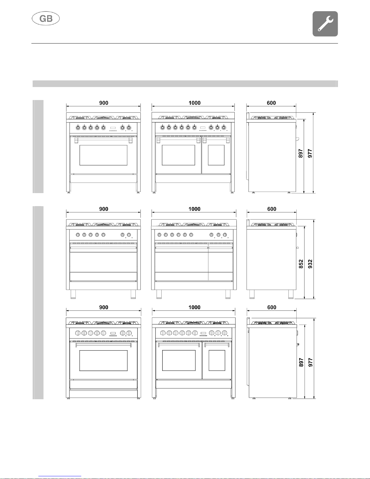
3. Installation
DIMENSIONS (mm)
DERBY
PARTY
Instructions for the installer
9
3.1 General warnings
The following operations must be carried out by a qualified installing technician. The
installing technician is responsible for correctly installing the appliance according to
current safety standards. Before using the appliance, remove the protective plastic on the control
panel, stainless steel parts, etc...
This appliance shall be installed only by authorised personnel and in accordance with the
manufacturer’s installation instructions, local gas fitting regulations, municipal building
codes, water supply regulations, electrical wiring regulations, AS 5601/AG 601 - Gas
Installations and any other statutory regulations. Before using the appliance, remove the
protective plastic on the control panel, stainless steel parts, etc...
The manufacturer declines any responsibility for damage incurred by persons, animals or
objects that is caused by not following the above guidelines (cfr. chapter “2. Warnings for
safety and use”).
The technical data is indicated on the plate located on the back of the appliance. The adjustment
conditions are shown on a label applied to the packing and the appliance.
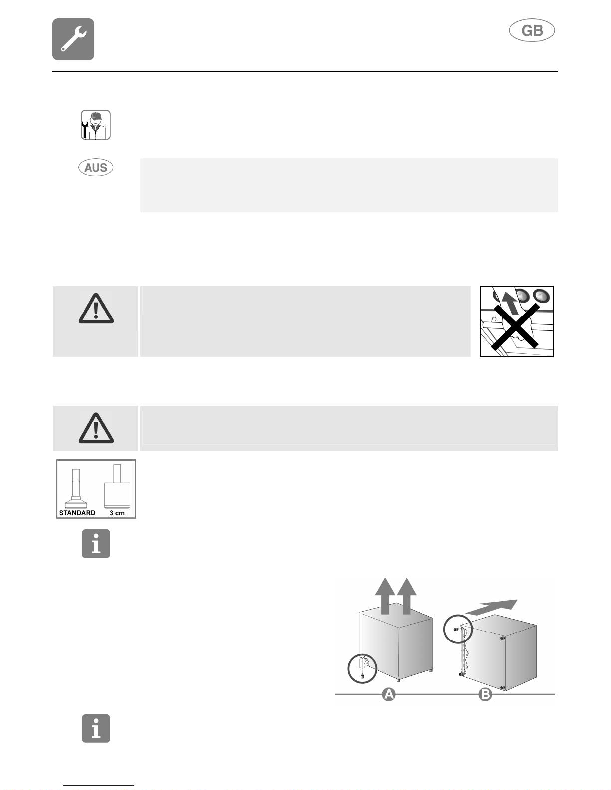
Do not use the oven door handle
for lifting or handling, including while
unpacking the appliance.
3.2 Replacing the adjustable feet
The cooker comes with standard feet, already installed.
The standard feet allow you to adjust the height so that you can level the cooker to the floor; the
cooker becomes unstable if you unscrew them too much.
To raise the cooker, you should replace the standard feet with higher ones (supplied with some
models or ordered from your retailer) for an extra 3 cm.
Before turning the cooker over, we recommend removing all the parts that are not stably attached
to it, in particular the cooking hob grids and burners. To lighten the weight of the cooker, the
accessories inside the oven may also be removed, thereby preventing accidental damage during
the overturning operation.
Proceed in either of the following ways to
replace the feet:
A Lifting the cooker off the floor.
B Laying the cooker on its back.
Remove the feet from the packing and
screw them to the bottom of the cooker.
Make the final adjustment
of the feet, to
level the cooker to the floor,
after
completing the gas and electrical
connections.
Should you need to drag the equipment, tighten the feet all the way and then adjust them after
placing it where expected.
Instructions for the installer
10
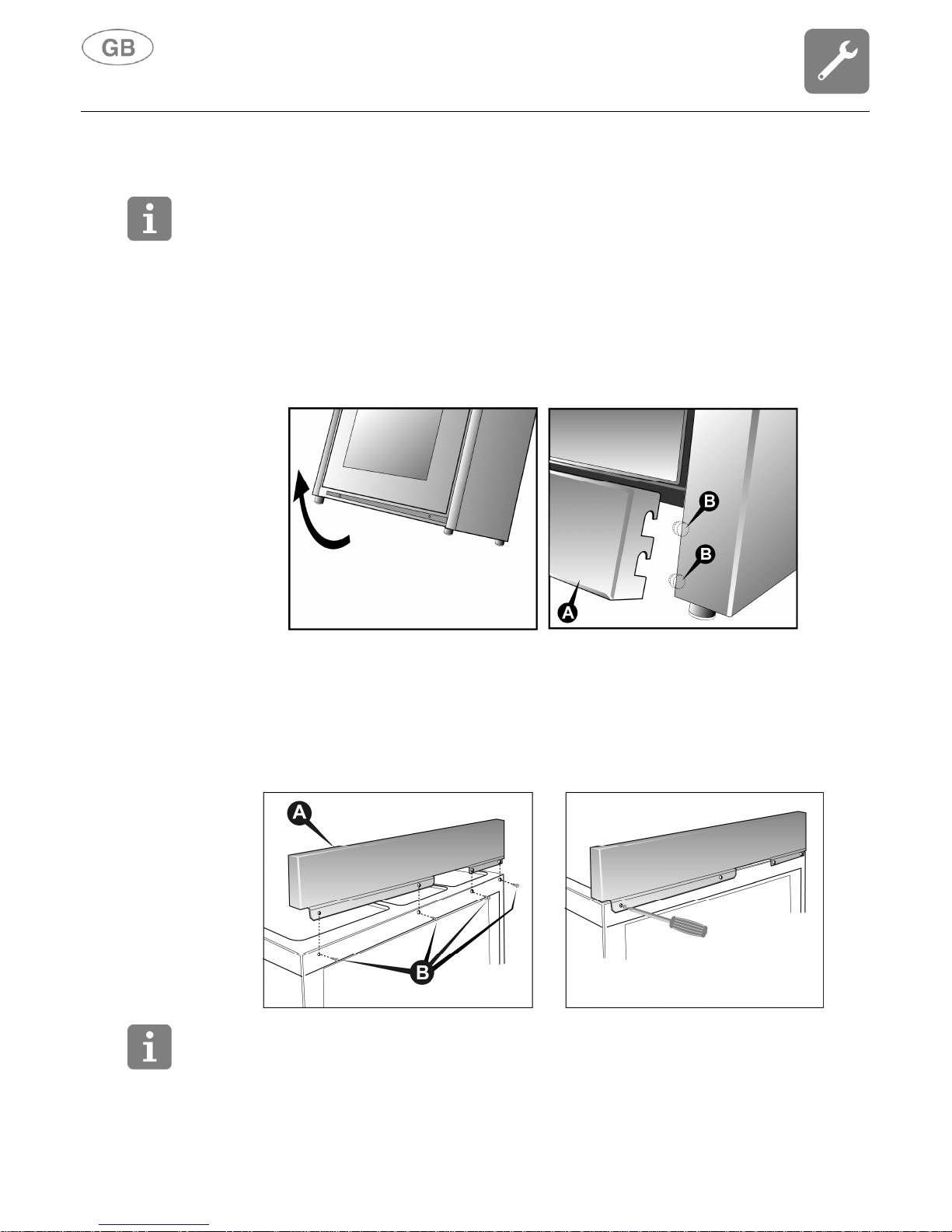
3.3 Fitting the front moulding
For some cooker models, a front moulding is available to complement its aesthetics.
Before turning the cooker over, we recommend removing all the parts that are not stably attached
to it, in particular the cooking hob grids and burners. To lighten the weight of the cooker, the
accessories inside the oven may also be removed, thereby preventing accidental damage during
the overturning operation.
To assemble, proceed as follows:
• tilt the cooker backwards;
• align the moulding A with the mounting position as shown in the illustration;
• apply the moulding until it fits into the mounting position;
• pull the moulding downward so that it hooks onto the 4 pins B (two on each side) present on
the cooker.
3.4 Fitting the backguard (only available on certain models)
Proceed as follows to install:
• rest the backguard A on the back of the surface, making sure the holes are aligned.
• tighten the 4 screws B using a Phillips screwdriver.
Any yellowing of the steel over time, which is completely natural, in no way alters its original
characteristics. It can be removed using specific steel cleaning products.
Instructions for the installer
11
3.5 Electric connection
Make sure that the voltage and the size of the mains corresponds to the specifications shown on
the plate located on the back of the appliance.
A second plate, including detailed information about the model and serial number, is placed inside
the equipment on the left side and is visible on opening the oven door.
These plates must never be removed.
The plug at the end of the power supply cable and the wall socket must be the same type and must
comply with current electric standards. Check that the mains is adequately earthed. Once the
appliance has been installed make sure that the plug is accessible to allow the periodical check-up.
Prepare an omni-polar cutoff device on the power supply line of the appliance with a contact
opening distance equal to or more than 3 mm, located in a convenient position near the appliance.
Do not use reducers, adapters or shunts.
Before making the electric connection, make sure of the efficiency of the earthing.
Make sure that the relief valve and the home wiring system are able to withstand the appliance
load.
The yellow/green earth cable must not be subject to cutoffs.
The electric cable must not come into contact with parts whose temperature is more than 50°C
higher than room temperature.
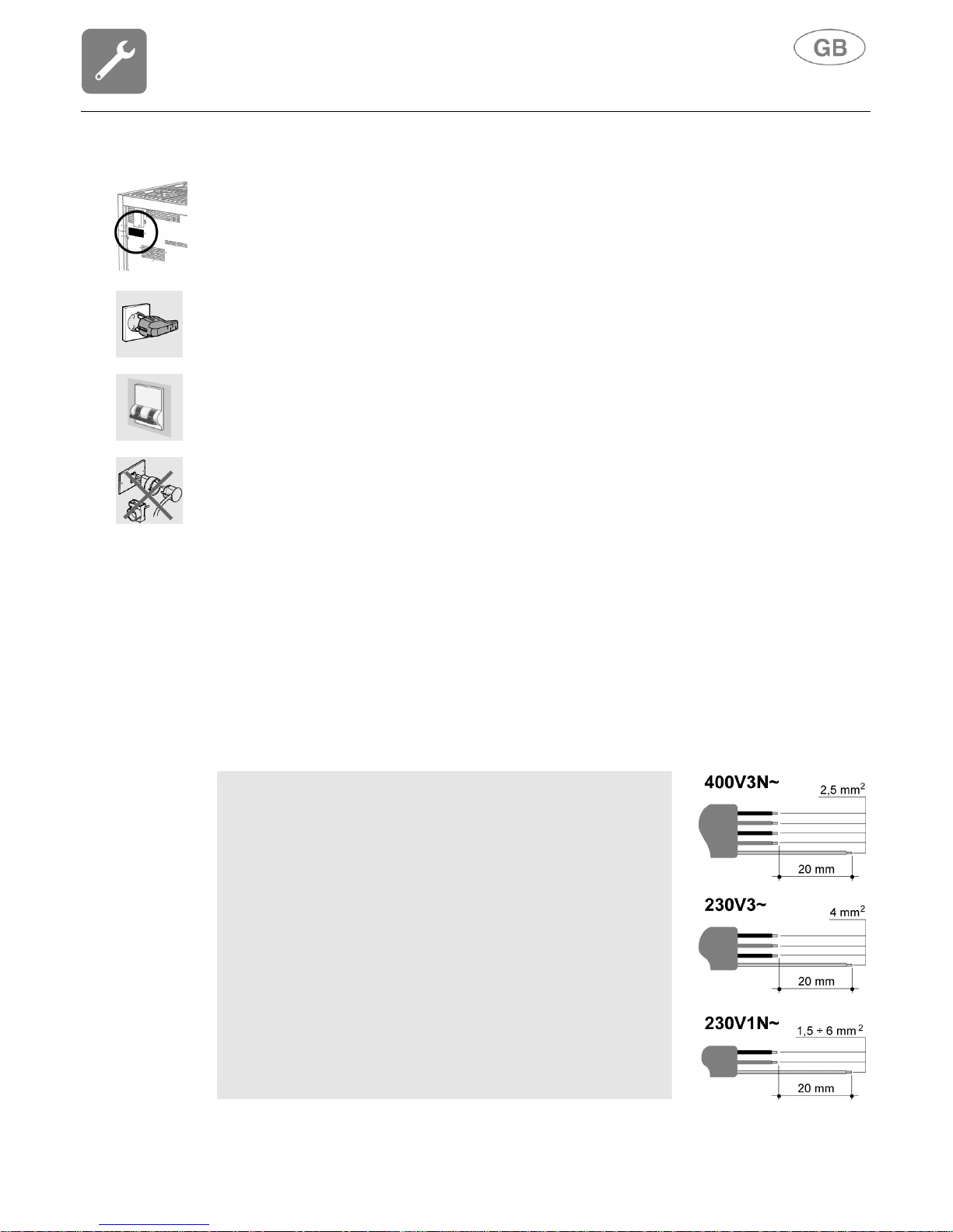
3.5.1 Electric power cable section
According to the type of power supply, use a cable that conforms to the following table.
Running at 400V3N~ (models connected according to DIAGRAM
"A"): use a pentapolar cable type H05RR-
F (cable measuring 5 x
2.5 mm2).
Running at 230V3~ (models connected according to DIAGRAM
"C" but commutated by the
installer according to DIAGRAM
"B"): use a tetrapolar cable type H05RR-
F (cable measuring 4 x 4
mm2).
Running at 230V1N~ (models connected according to DIAGRAM
"C"): up to 2.9 kW use a tripolar cable type H05RR-
F (cable
measuring 3 x 1.5 mm2); between 2.9 kW and 5.4 kW
use a tripolar
cable type H05RR-F (cable measuring 3 x 2.5 mm2); between 5.
4
kW and 7 kW use a tripolar cable type H05RR-
F (cable measuring
3 x 4 mm2); over 7 kW use a tripolar cable type H05RR-
F (cable
measuring 3 x 6 mm2).
The end to be
connected to the appliance must have the earth wire
(yellow-green) at least 20 mm longer.
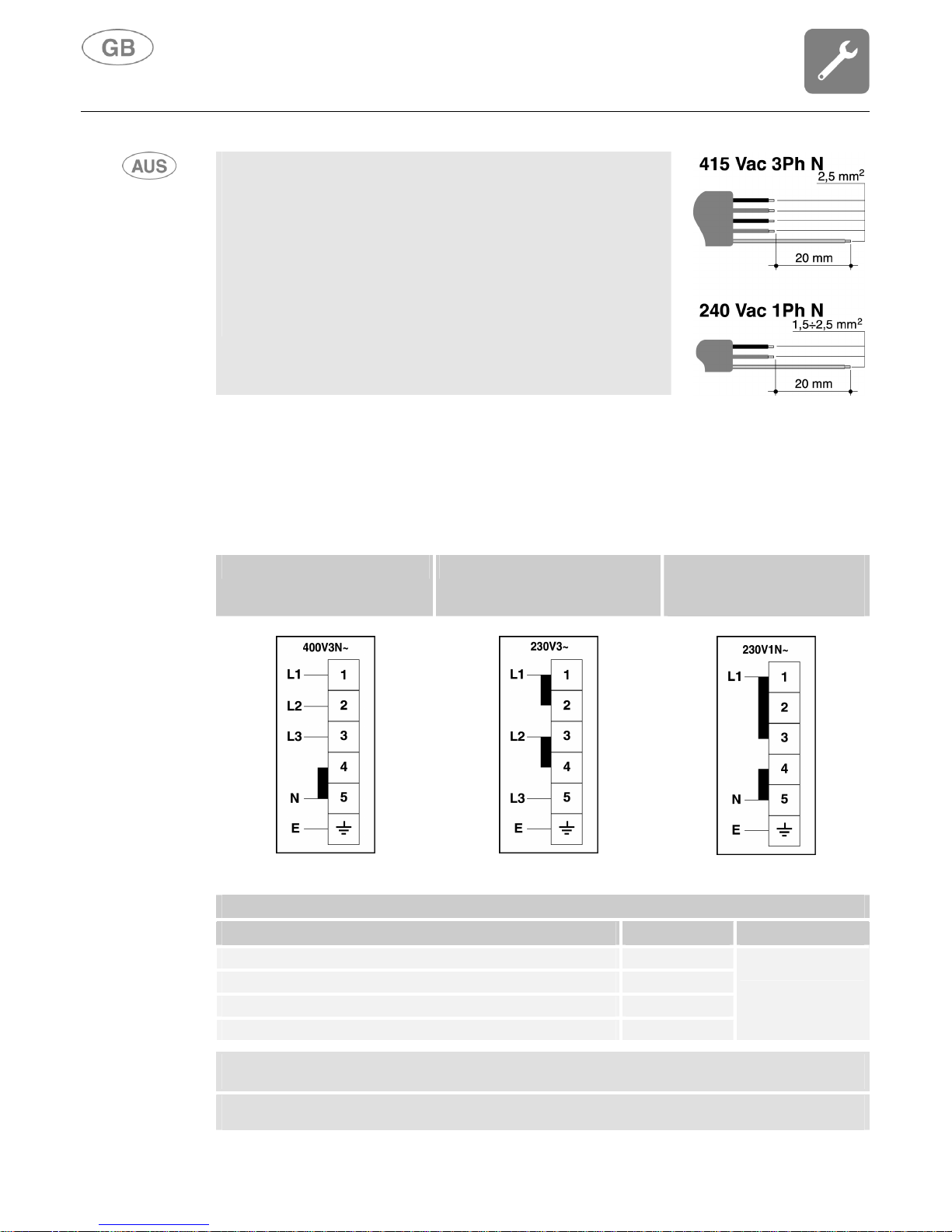
Instructions for the installer
12
Running at 415 Vac
3Ph N (models connected according to
DIAGRAM "A"): use a pentapolar cable type H05RR-
F (cable
measuring 5 x 2.5 mm2).
Running at 240 Vac 1Ph N (models connected according to
DIAGRAM "B"): up to 10.44 MJ use a tripolar cable type H05RR-
F
(cable measuring 3 x 1.5 mm2); between 10.44 MJ and 19.44 MJ
use a tripolar cable type H05RR-F (cable measuring 3 x 2.5 mm2).
The end to be connected to the appliance must have the earth wire
(yellow-green) at least 20 mm longer.
3.5.2 Type of power supply
It is possible to obtain different connections according to the voltage, simply by moving the
unconnected cable ends on the terminal board as shown in the following diagrams.
According to the model, consult the table "C
ONNECTION TO THE TERMINAL BOARD
".
DIAGRAM “A” DIAGRAM “B” DIAGRAM “C”
ORIGINAL CONNECTION
SET BY MANUFACTURER
.
CONNECTION TO THE TERMINAL BOARD
MODEL POWER kW POWER SUPPLY
COOKER 5 BURNERS (1 OVEN) 2.9
COOKER INDUCTION HOB (1 OVEN) (6 ELEMENTS) 10.1
COOKER 6 BURNERS (2 OVENS) 3.9
COOKER INDUCTION HOB (2 OVENS) (6 ELEMENTS) 11.1
DIAGRAM “C”
M
ODELS CONNECTED ACCORDING TO DIAGRAM
"A"
CAN BE COMMUTATED BY THE INSTALLER ACCORDING TO DIAGRAM
"B".
M
ODELS CONNECTED ACCORDING TO DIAGRAM
"C"
CAN BE COMMUTATED BY THE INSTALLER ACCORDING TO DIAGRAM
"A".
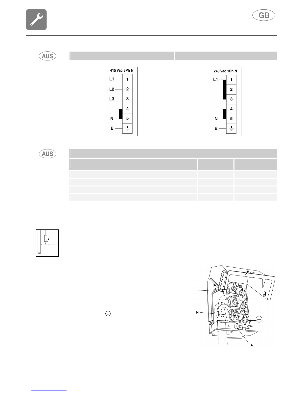
Instructions for the installer
13
DIAGRAM “A” DIAGRAM “B”
CONNECTION TO THE TERMINAL BOARD
MODEL
POWER
kW
CURRENT
DRAW (amps)
COOKER 5 BURNERS (1 OVEN) 2.9 12
COOKER INDUCTION HOB (1 OVEN) (6 ELEMENTS) 10.1 42
COOKER 6 BURNERS (2 OVENS) 3.9 16
COOKER INDUCTION HOB (2 OVENS) (6 ELEMENTS) 11.1 42
3.5.3 Replacing the electric cable
To replace the electric cable, it is necessary to access the terminal board. It is located on the back
of the appliance as shown in the figure.
To replace the cable, proceed as follows:
• open the terminal board box;
• unscrew the screw A that locks the cable;
• loosen the screw contacts and replace the cable
with one of the same length that corresponds to the
specifications in the table in section “3.5.1 Electric
power cable section”;
• the "yellow-green" earth wire must be connected to
the terminal and must be approximately 20 mm
longer than the line cables;
• the neutral "blue" wire must be connected to the
terminal marked with the letter N;
• the line wire must be connected to the terminal
marked with the letter L.
Instructions for the installer
14
3.6 Ventilation in rooms with gas appliances
This appliance is not connected to an exhaust device for products of combustion. It must therefore
be installed and connected in compliance with current installation standards. Pay particular
attention to standards applied to room aeration.
This appliance is not connected to an exhaust device for products of combustion. Ventilation must
be in accordance with AS5601/AG 601 - Gas Installations. In general, the appliance should have
adequate ventilation for complete combustion of gas, proper flueing and to maintain temperature of
immediate surroundings within safe limits. Pay particular attention to standards applied to room
aeration.
This appliance can only be installed in ventilated rooms, according to current standards, so as to
allow, with openings onto external walls or appropriate ducts, for correct natural or forced
ventilation that permanently and sufficiently ensures both the air intake necessary for correct
combustion and the expelling of vitiated air. It is recommended that the appliance have a
rangehood fitted directly above or ceiling fan in close proximity to the appliance.
Using a gas cooking appliance produces heat and humidity in the room where it is installed. Ensure
good room ventilation: keep natural ventilation grilles open or install a mechanical ventilation device
(ducted extraction hood).
Intensive and prolonged appliance use may require supplementary ventilation, for example, opening
a window, more effective ventilation, or increasing the extraction hood power, if installed.
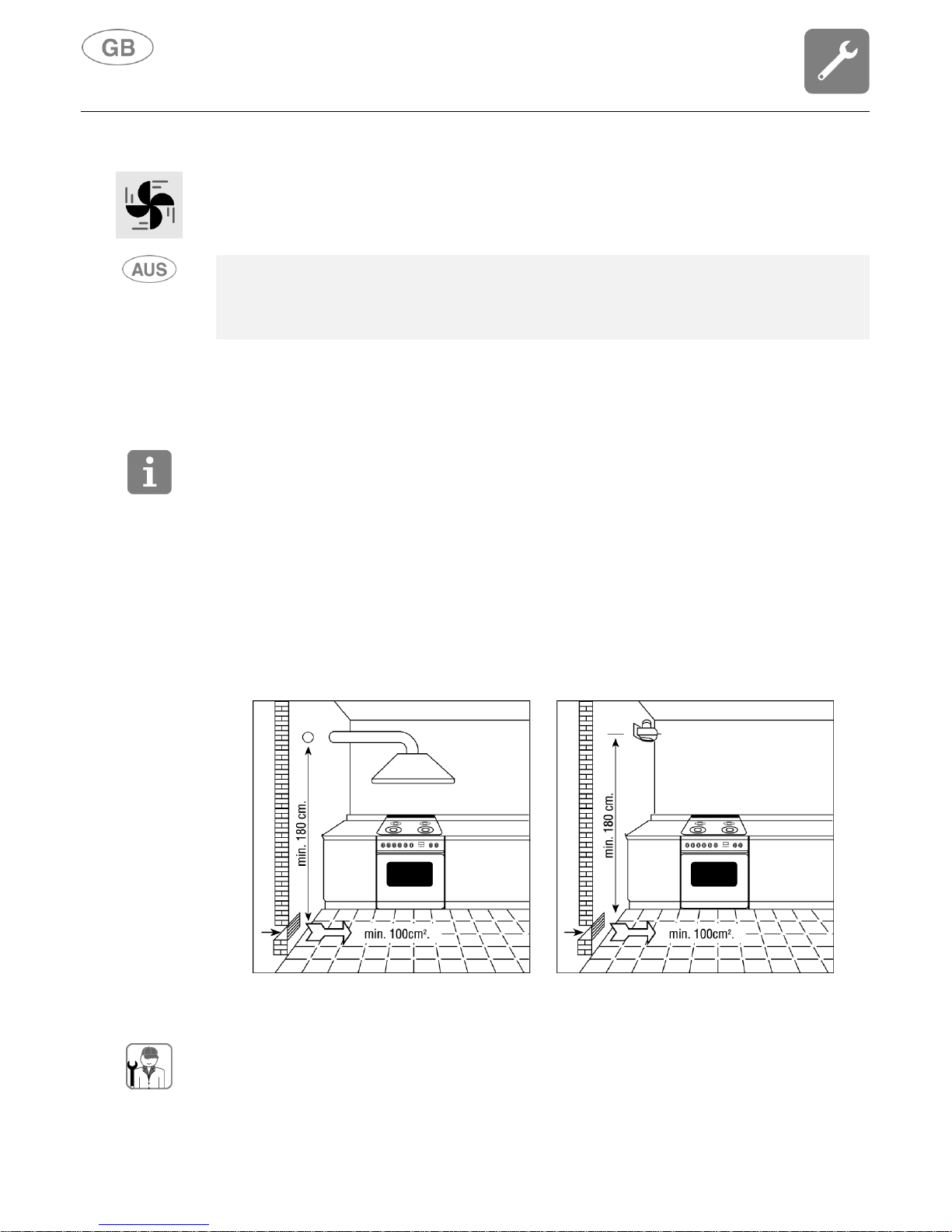
If this is the only gas appliance in the room, it is necessary to install a hood so as to expel vitiated
air naturally and directly, with a rectilinear vertical duct at least twice as long as its diameter and
having a minimum section of at least 100 cm2.
For the essential air intake into the room, it is necessary to prepare a similar opening of at least
100 cm
2
that communicates directly outside, situated close to floor level so as not to be obstructed
from either inside or outside and so as not to disturb the combustion of the burners and the correct
expelling of vitiated air and with a height difference from the exit opening of at least 180 cm.
Remember that the quantity of air necessary for combustion must not be lower than 2 m3/h per kW
of power (see total power in kW shown on the appliance plate).
In all other cases, i.e. when other gas appliances are present in the same room, or, if it is not
possible to have natural direct ventilation, it is necessary to create natural, indirect ventilation or
forced ventilation: for this type of operation, it is necessary to contact a qualified technician
for installing and creating the ventilation system in strict compliance with the guidelines set
out in current standards.
The openings should be positioned so as not to allow the formation of any unpleasant air current
for the occupants. Furthermore, it is forbidden to use flues already used by other appliances to
expel products of combustion.
electric fan
Instructions for the installer
15
3.7 Gas connection
Gas-powered devices for home use, which are not connected to a conduit for the evacuation of
combustion products, must not cause a concentration of carbon monoxide that could pose a health
risk to the persons exposed in relation to the time of exposure.
We recommend checking that the appliance is properly set up for the type of
gas distributed. The connection to the gas pipes must be made in a
workmanlike manner, in compliance with current standards that prescribe the
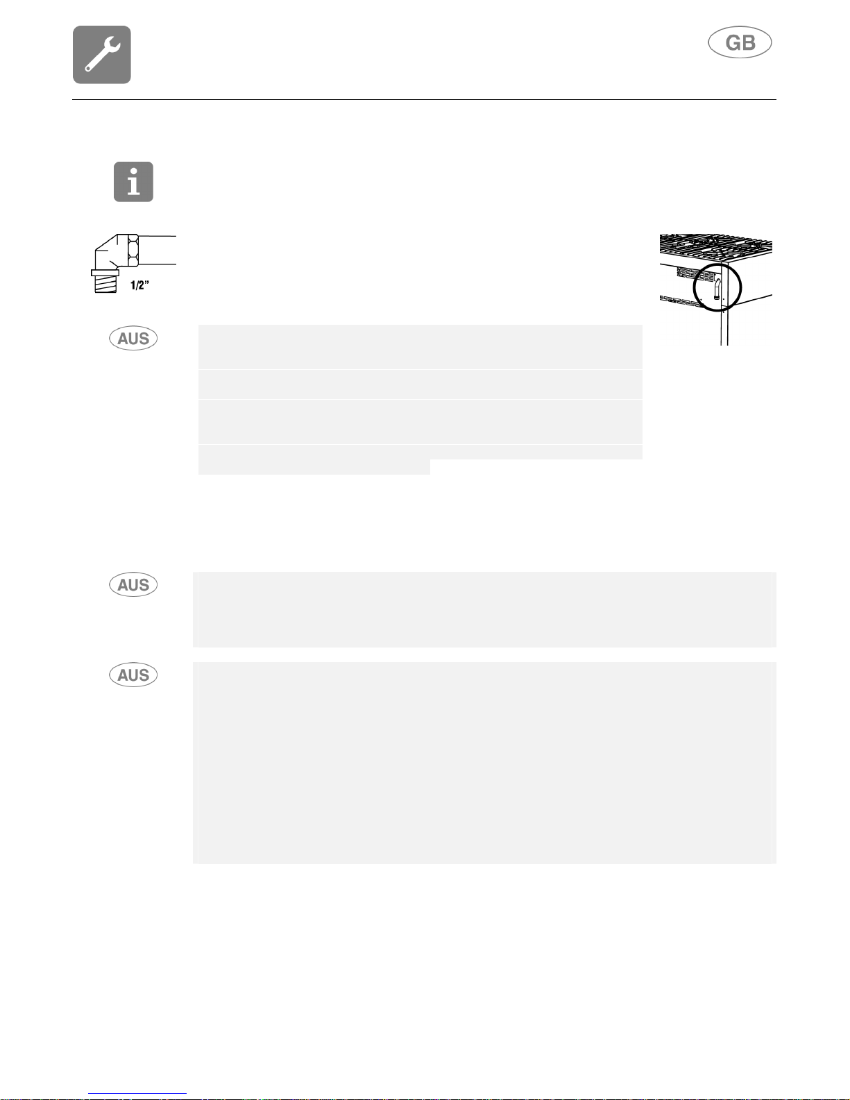
installation of a safety tap at the end of the pipe. The threaded ½" gas
connection pipe is located at the rear on the right hand side of the appliance.
We recommend checking that the appliance is properly set up for the type of
gas distributed. The connection to the gas pipes must be made in a
workmanlike manner, in compliance with current standards that prescribe the
installation of a safety tap at the end of the pipe. The Gas Connection is
male ½" BSP and is situated at the left hand, top rear of the appliance,
74mm from the side and 700mm from the floor (cookers) or 25mm from the
underside (cooktops). The appliance is factory set for Natural gas. The test
point pressure should be adjusted to 1.00kPa with the Wok and Semi-Rapid
burners operating at maximum on 120cm models and the Wok burner
operating at maximum on 90cm models.
For butane and propane, a pressure reducer conforming to standards regulations in force should
be prepared. The seals must conform to standards regulations in force.
Once the gas has been connected, check the seal of the unions with a soap and water solution.
For propane a pressure regulator set to provide a supply pressure of 2.75kPa conforming to
standards regulations in force should be fitted. The seals must conform to standards regulations in
force. Fit the test point assembly supplied with the appliance to the gas connection when installing
for use with Propane Gas. Once the gas has been connected, check the seal of the unions with a
soap and water solution.
It is possible to connect the gas in the following ways:
• using iron or copper rigid pipe as specified in AS5601 table 3.1;
• using a Plumbezy flexible hose, AGA approval number 6196, 10mm ID, class D and between
1-1.2m long in accordance with AG601 for a "high level connection". For cookers supplied with
a flexible hose the restraining chain fitted to the rear of the cooker must be fixed to the wall as
follows.
1. Supply fixing points on either side of the cooker (vertically in line with the chains attached)
at approxiametely 100mm above floor level.
2. Firmly secure the chains at these points.
3. Supply similar fixing points at approxiametely 700mm above floor level using open hooks.
4. Loop the chains over these hooks to prevent the cooker from accidentally tilting.
5. Removing the chains from the hooks enables the cooker to be pulled out for service. Ensure
that the chains prevent stress on the hose assembly while the cooker is in this position.
Instructions for the installer
16
AT
●
BE
●
CH
●
DE
●
DK
●
ES
●
●
FI
●
●
FR
●
GB
●
IE
●
IT
●
●
LU
NL
●
NO
●
●
PT
●
●
SE
●
●
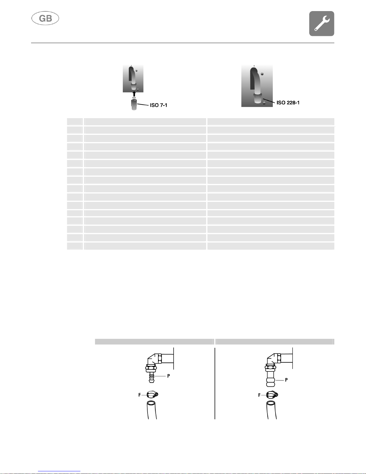
It is possible to connect the gas in the following ways:
• using iron or copper rigid pipe;
• using uninterrupted stainless steel flexible pipe with a mechanical fitting conforming to
standards regulations in force (maximum length of extended pipe 2000 mm). The pipe should
be connected straight to the elbow of the ramp;
• by inserting a flexible rubber pipe conforming to standards regulations in force. This pipe
should be coupled straight to the rubber-holder P corresponding to the gas used, and locked
with a clamp F conforming to standards regulations in force. In the latter case, check the expiry
date printed on the pipe and replace it before that date.
LPG NATURAL GAS
 Loading...