

Page 1

ITZV6
Flex-ATX Intel 810
Socket 370 Motherboard
USER’S MANUAL
Model : ITZV6
Manual Version : English, version 1.1
Release Date : May 18th, 2000
Page 2

Contents
Chapter 1 Overview
General Description................................................................1-1
Check Your Items............................................................. ......1-1
ITZV6 Specifications..............................................................1-2
Motherboard Layout................................................................1-3
Chapter 2 Hardware Installation
Set Jumpers................................................................................2-2
Clear CMOS...............................................................................2-3
Install CPU.................................................................................2-4
CPU Setting................................................................................2-5
CPU Type Selection.........................................................2-5
CPU Clock Frequency......................................................2-6
Connectors................................................................................. 2-7
Panel Connector...............................................................2-7
Power Connector.............................................................2-7
Fan Connector................................................................. 2-8
PS/2 Mouse & Keyboard Connectors...............................2-9
USB device Connector......................................................2-9
Serial Device com1, VGA & Printer Connectors.............2-10
Floppy drive Connector....................................................2-10
IrDA Connector................................................................2-11
IDE Hard Disk Connector................................................2-11
LAN Connector ..............................................................2-12
Game/Audio & CD_IN Connectors.................................2-12
System Memory Installation...................................................... 2-13
Install DIMM...................................................................2-14
Removing a Memory Module.........................................2-14
Page 3

Contents
Chapter 3 CMOS Setup Utility
CMOS Setup Main........................................................... 3-1
Standard CMOS Setup......................................................3-3
Advanced BIOS Features..................................................3-6
Advanced Chipset Features...............................................3-9
Integrated Peripherals........................................................3-11
Power Management Setup.................................................3-15
Load Fail-Safe Defaults.....................................................3-17
Load Optimized Defaults...................................................3-18
Set Supervisor / User Password.........................................3-19
Save & Exit Setup..............................................................3-20
Exit Without Saving...........................................................3-20
Chapter 4 Software Utility
Installing Interface................................................................4-1
Installing Driver Location.................................................... 4-2
Installing ADOBE Acrobat Read Driver.............................. 4-2
Page 4

Copyright
Copyright 2000 by this company. All rights reserved.
No part of this publication may be reproduced, transmitted, transcribed,
stored in a retrieval system or translated into any language in any form or by
any means, electronic, mechanical, magnetic, optical, manual or otherwise,
without the prior written consent of the copyright holders.
Notice
The contents of this publication are subject to change. This company
reserves the right to alter the contents of this publication at any time and
without notice.The contents of this publication may contain inaccuracies or
typographical errors and is supplied for informational use only.
Intel and Pentium are registered trademarks of Intel Corporation.
OS/2 and IBM are registered trademarks of Intemational Business Machines.
Windows and MS-DOS are registered trademarks of Microsoft Corporation.
AWARD is a registered trademark of Award Software Inc.
Other brand, corporate, and product names may or may not be registered
trademarks or copyright of their respective companies.
Page 5

FCC & DOC Compliance
Federal communications Commission Statement
This device complies with FCC Rules Part 15. Operation is subject to the following two
conditions:
! This device may not cause harmful interference.
! This device must accept any interference received, including interference
that may cause undesired operation.
This equipment has been tested and found to comply with the limits for a Class B
digital device, pursuant to Part 15 of the FCC Rules. These limits are designed to
provide reasonable protection against harmful interference in a residential installation.
This equipment generatesm uses and can radiate radio frequency energy and, if not
installed and used in accordance with the manufacturer’s instructions, may cause harmful
interference to radio communication. However, there is no guarantee that interference will
not occur in a particular installation. If this equipment does cause harmful interference to
radio or television reception, whichcan be determined by turning the equipment off and on,
the user is encouraged to try to correct the interference by one or more of the following
measures:
! Re-orient or relocate the receiving antenna.
! Increase the separation between the equipment and the receiver.
! Connect the equipment to an outlet on a circuit different from that to which
the receiver is connected.
! Consult the dealer or an experienced radio/TV technician for help.
Warning
The use of shielded cables for the connection of the monitor to the graphics card is required
to assure compliance with FCC regulations changes or modifications to this authority to
operate this equipment.
Page 6

Chapter 1 Overview
General DescriptionGeneral Description
General Description
General DescriptionGeneral Description
Thanks for purchasing EUPA ITZV6 Socket 370 motherboard. ITZV6 is based on
Intel 810 chipset -- 82810(GMCH) & 82801AA(ICH) which was for Celeron
(PPGA) and Copperminer (FC-PGA) Socket 370 processors. The product integrates
2D/3D graphics accelerator. It design 1 DIMM supporting 256MB system memory
with PC 100. Also it employs AC 97 system, Ultra DMA 33/66 function, dual USB
connectors and PCI IDE controller. This user s manual contains all the information
and features that show you how to control ITZV6 motherboard. Please take a moment
to familiarize yourself with the design and organization of this manual.
TM
Check Your Items
This ITZV6 motherboard package contains the following items. Please inspect the
package contents and confirm that everything is there. If anything is missing or
damaged, call your vendor for instructions before operating.
The Package includes:
"
" One Floppy Interface Cable
" One IDE Interface Cable
" One Motherboard Resource CD
" One User’s Manual
1-1
One ITZV6 motherboard
Page 7
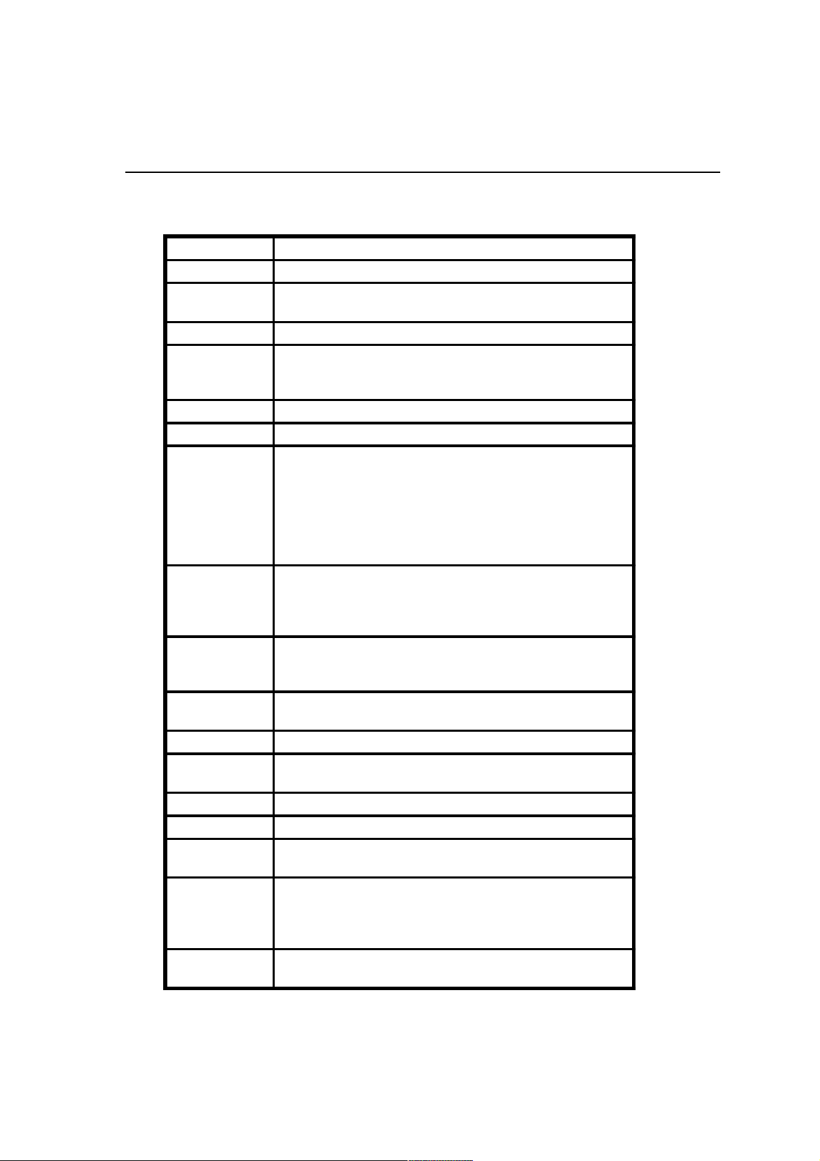
ITZV6 Specifications:ITZV6 Specifications:
ITZV6 Specifications:
ITZV6 Specifications:ITZV6 Specifications:
Form Factor FLEX-ATX
Board Size 17.0cm x 17.0cm
CPU
System Memory DIM M 168-pin x 1, SDRAM maximum 256MB with PC100 SDRAM
Chipset
Sound Function ON board AC'97 system, Crystal4299 Audio Codec
Graphic 2D/3D graphic accele rator i752 Bu ilt in 82810 GMCH
I/O Interface
Parallel Port
Floppy Interface
IDE Interface
Fuse Support Recoverable fuse for USB,KB & MOUSE
RTC and Battery
Power Connector ATX
Power On Function Keyboard / Mouse power on
Other Key Feature
BIOS
LED Indicator
Supports Socket 370 Celeron(PPGA), Cu(FC-PG A) and further CPUs
Supports FSB 66/100MHz
Intel 82810 GMCH
Intel 82801AA ICH
Intel 82802AB
2 USB Ports
1 Audio Port (MIDI / game port, Line-in, Line-out, Mic-in)
1 LAN Port (10M / 100M auto detect)
1 PS/2 Mouse, 1 PS/2 Keyboard
1 VGA port
1 IrDA pinheader
1 serial port
One parallel port supports:
-SPP-standard parallel port
-EPP-enhanced parallel port
-ECP-extended capabilities port
Support drivers inches/format with:
-3.5 inches-720KB/1.44MB/2.88M B
-5.25 inches-360KB/1.2MB
One IDE Interface support 2 x IDE HD D or CDR OM
Support PIO Mode 2, ULTRA DMA/33 & U LTRA D MA/66
Built in ICH
Lithium(CR-2032) battery
Monitor voltage and system environment temperature
Wake on Modem
Aw ard BIO S
ITE Hardware Monitor
Supports virus warning
Supports Flash / Upgrade BIOS functions
System Power LED
HDD activity L ED
Overview
1-2
Page 8
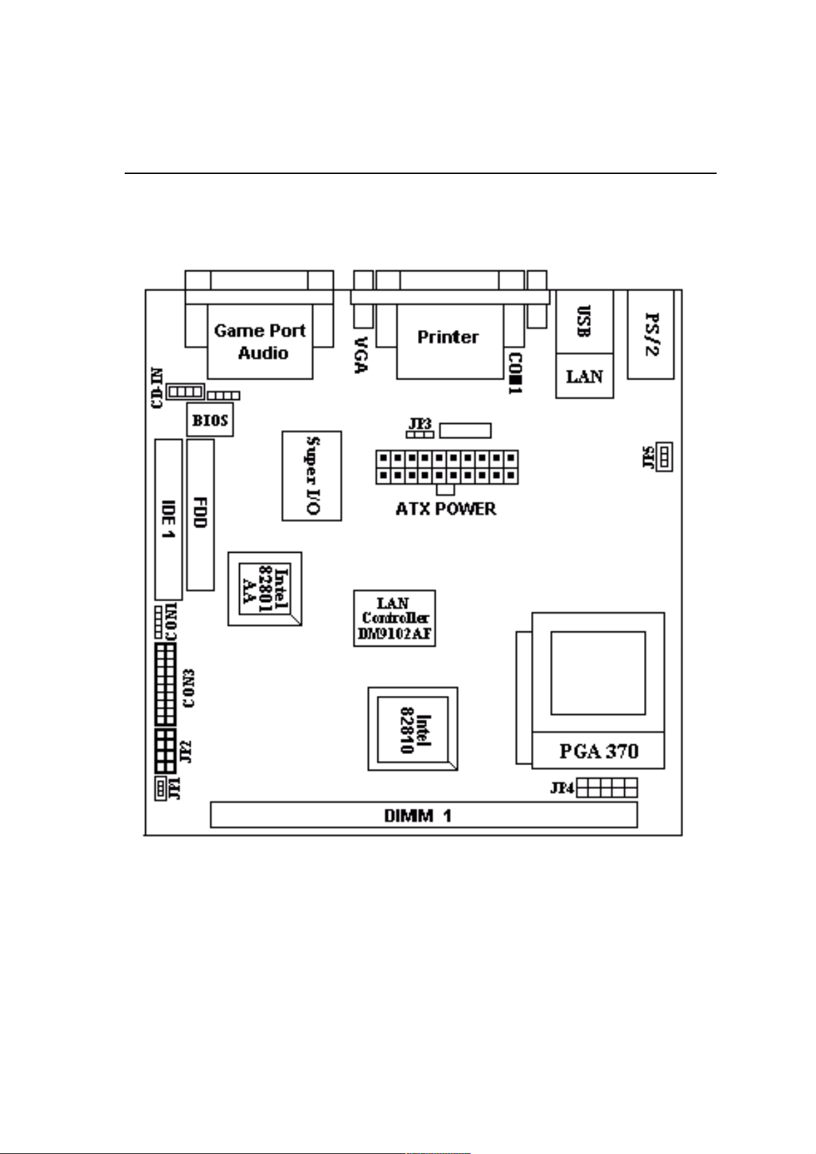
Overview
Motherboard Layout:Motherboard Layout:
Motherboard Layout:
Motherboard Layout:Motherboard Layout:
1-3
Page 9

Jumpers
1. JP3 Clear CMOS
2. JP2 Select CPU clock frequency
3. JP4 Select CPU type
Expansion Slots
1. DIMM Support 168-pin DIMM Memory
Connectors
1. PS/2 KB PS/2 Keyboard Connector
2. PS/2 Mouse PS/2 Mouse Connector
3. LAN LAN Connector
4. USB Universal Serial Bus Port1 and Port2
5. Printer Printer (Parallel) Port Connector
6. ATX Power ATX Power Connector
7. JP1 System Fan Connector
8. JP 5 CPU Fan Connector
9. Floppy Floppy Drive Connector
10. IDE 1 Primary IDE Connector
11. CON 1 IrDA Connector
12. CON 2 Audio CD-IN Connector
13. Panel(CON3)
- PWR LED ATX Power LED (3pins)
- SPEAKER Chassis Speaker (4pins)
- HDD LED HDD LED (2pins)
- RESET Reset Switch (2pins)
- PWR ON ATX Power Switch (2pins)
Overview
1-4
Page 10

Chapter 2 Hardware Installation
This chapter gives you a step-by-step procedure on how to install your system and set
jumper. The motherboard has several user-adjustable jumpers on the board that allow
you to configure your system to suit your requirements.
Cautions: Protecting Against Electrostatic Discharge
Static electricity can harm delicate components inside your system. To prevent
static electricity damage, discharge static electricity from your body before you
touch any of your motherboard electronic components, such as the microproces-
sor. Observe the following precautions:
- Do not removes the motherboard from its anti-static packaging until you are
ready to install it into a computer case.
- Before you handle the motherboard in any way, touch a grounded, antistatic
surface, such as an unpainted portion of the system chassis, for a few seconds
to discharge any built-up static electricity.
- Handle add-in cards and modules by the edges or mounting bracket.
2-1
Page 11
Hardware Installation
Set Jumpers:Set Jumpers:
Set Jumpers:
Set Jumpers:Set Jumpers:
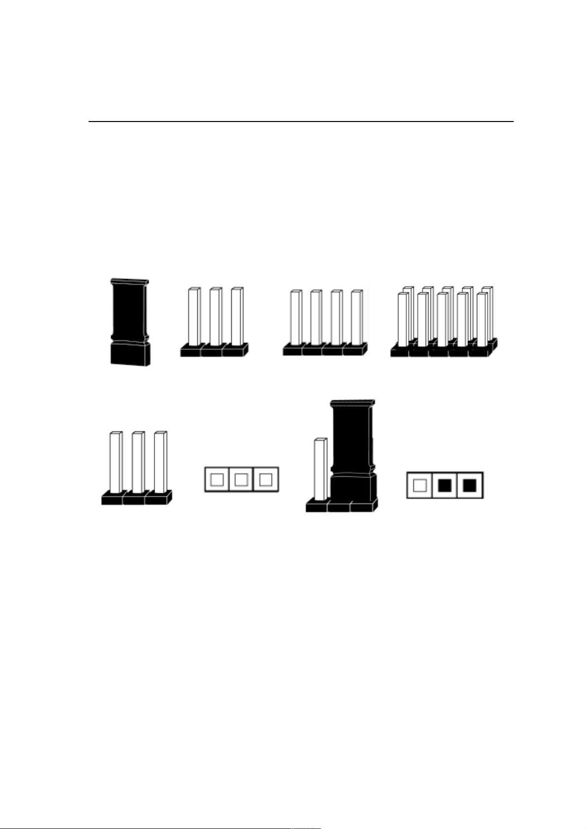
Jumpers are used to select the operation modes for your system. Each jumper on the
board has several metal pins with each pin representing a different function. A 1 is
written besides pin 1 on jumpers with several pins. To set a jumper, a plastic cap con-
taining metal contactor is placed over the jumper pins according to the required configu-
ration. A jumper is said to be shorted when the plastic cap has been placed on two pins
of it.The types of jumpers used in this manual are shown below:
1
3-pin Jumper
Open
4-pin Jumper
3
2
Jumper Block
Short
1
Jumper Cap
2
3
Note:
Users are not encouraged to change the jumper settings not listed in this manual. Chang-
ing the jumper settings improperly may adversely affect system performance.
2-2
Page 12
Hardware Installation
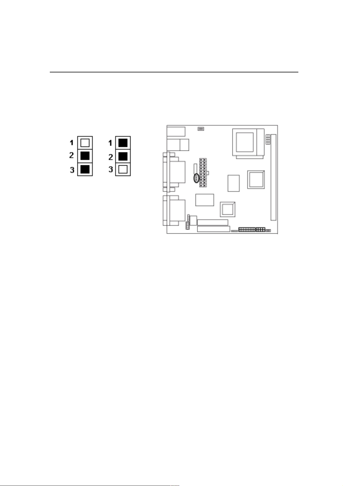
Clear CMOS: Clear CMOS:
Clear CMOS: JP3
Clear CMOS: Clear CMOS:
JP3 Clear CMOS
Clear CMOS
Normal
(Default)
To Clear CMOS, please follow the steps below:
1. Power off the system and unplug the chassis AC power cord.
2. Short JP3 at pin 2-3 for few seconds.
3. Set JP3 back to its Normal position at pin1-2
4. Plug the AC power cord to the chassis.
5. Power on the system and load the BIOS set up default.
2-3
Page 13
Hardware Installation
Install CPUInstall CPU
Install CPU
Install CPUInstall CPU
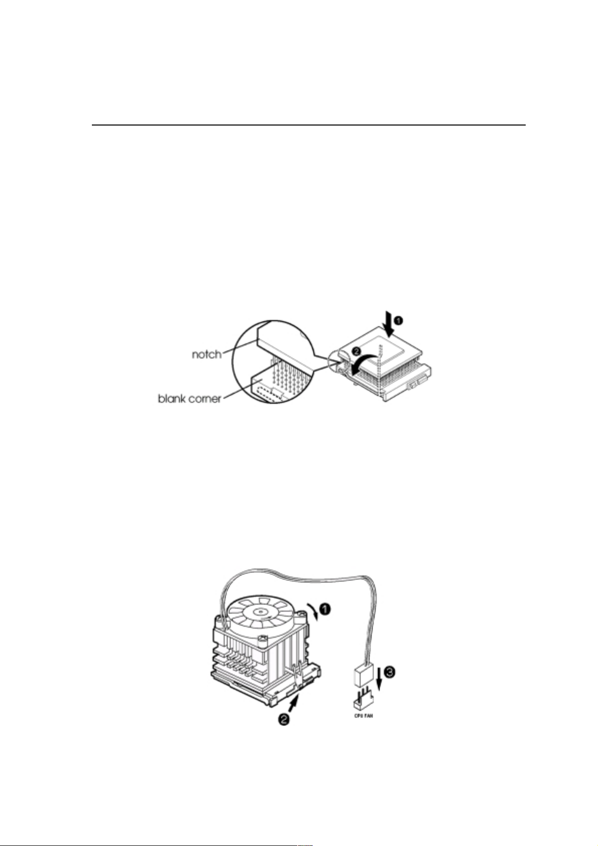
The CPU module resides in the socket 370 on the motherboard. Please following the
steps introduced below to complete the CPU installation.
1) Locate the new processor you are installing over the socket so that the notched
corner on the processor (pin 1) can be aligned with the blank corner on the socket.
Then gently push the processor straight into the socket until its pins are completely
inserted into the holes of the socket.
Caution:
If you install the processor chip in the wrong orientation, you may burn the chip
and void your warranty. So you should install it careful deeply.
2) Press the ZIF handle back to close it.
3) Attach the heat sink to the processor socket and then connect a fan connector
cable from the CPU fan to the CPU FAN connector.
2-4
Page 14
Hardware Installation
CPU SettingCPU Setting
CPU Setting
CPU SettingCPU Setting
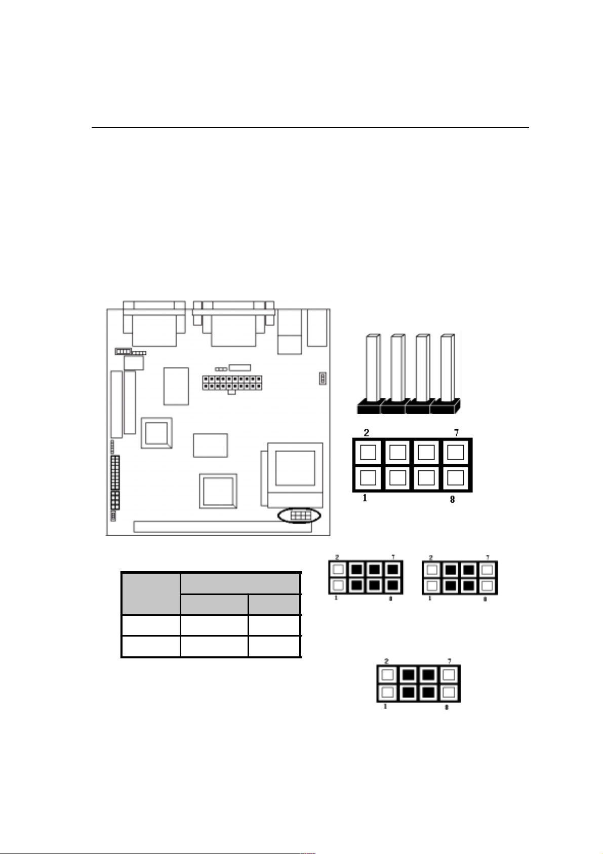
After installing the CPU, you must set the clock selection jumpers to match the fre-
quency of the CPU. Find the jumper labeled
JP2, set it (from pin 1 to 8, we call them
as FS0, FS1, FS2, FS3) according to the figure below and table for CPU clock fre-
quency.
JP4 is used for CPU Type Selection.
1 CPU Type Selection: JP4
JP4
CPU Type Selection
2-5
JP4 PIN
CPU TYPE
66MHz 10 0MHz
Celeron 3-4 5-6 7-8 3-4 5-6
Coppermine 3-4 5-6
66MHz
Celeron
100MHz
Coppermine
100MHz
Page 15
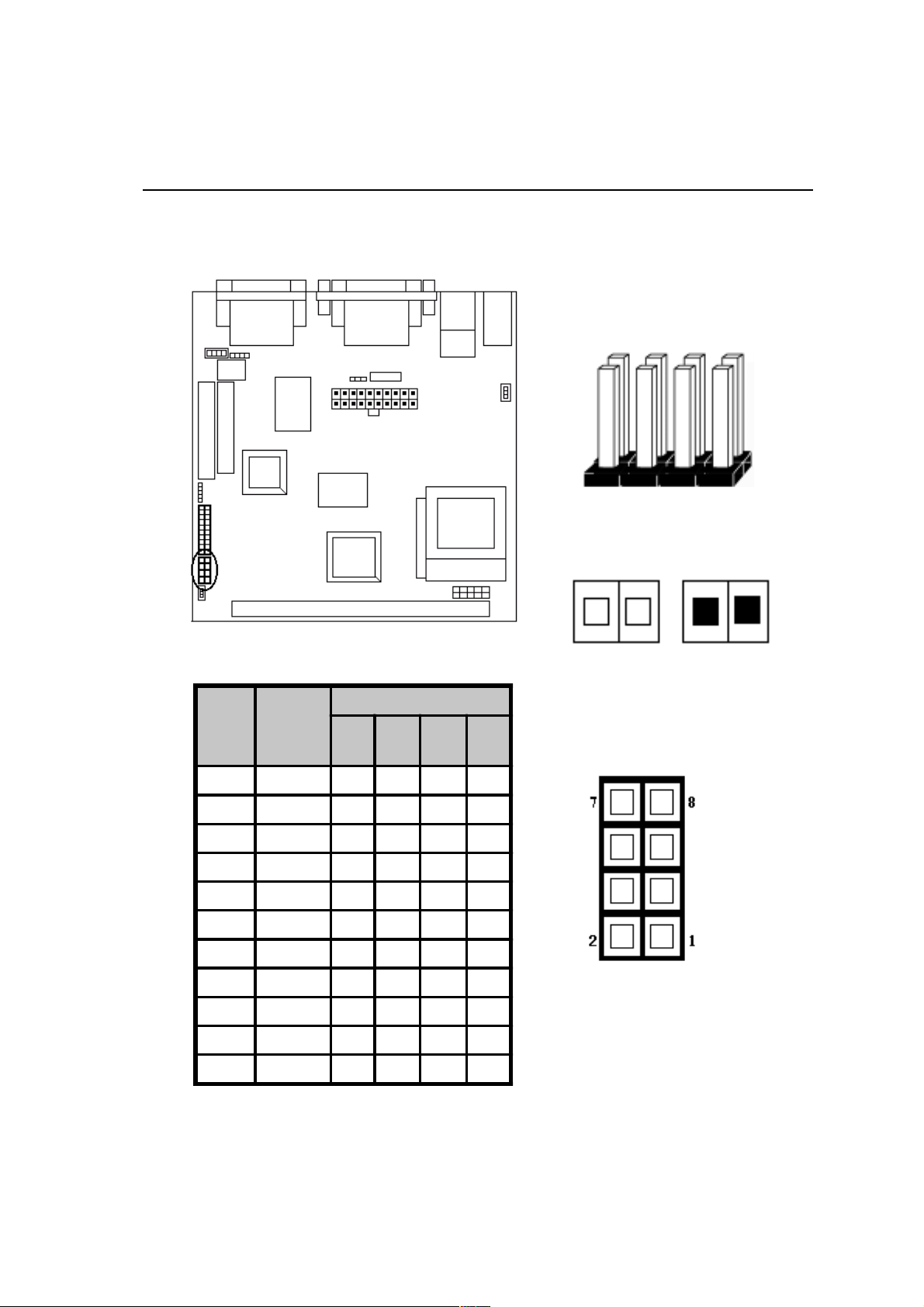
2 CPU Clock Frequency: JP2
Hardware Installation
JP2
OPEN (O) SHORT (S)
CPU
(MHz)
66.80 33.40 S S S S
68.00 34.00 O S S S
72.50 36.25 O O O O
100.30 33.43 S O S S
103.00 34.33 O O S S
118.00 39.33 S O S O
124.00 41.33 O O S O
133.70 44.57 S S O O
137.00 45.67 O S O O
140.00 46.67 O S S O
150.00 50.00 S O O O
PCICLK
(MHz)
FS0
(1-2)
JP2 PIN
FS1
(3-4)
FS2
(7-8)
FS3
(5-6)
JP2
.5
.5!
.5
.5
2-6
Page 16
Hardware Installation
Connectors:Connectors:
Connectors:
Connectors:Connectors:
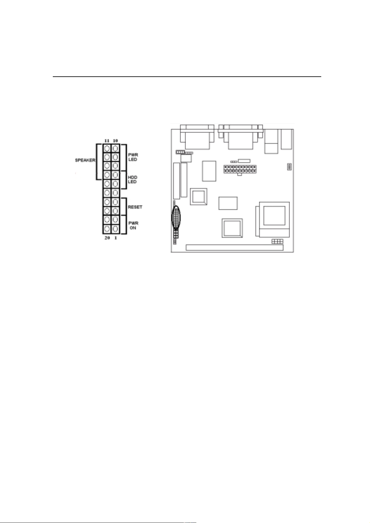
1. Panel Connector:
-POWER LED ATX Power LED (3-pins)
-SPEAKER Chassis Speaker (4-pins)
-HDD LED HDD LED (2-pins)
-RESET Reset Switch (2pins)
-PWR ON ATX Power Switch (2pins)
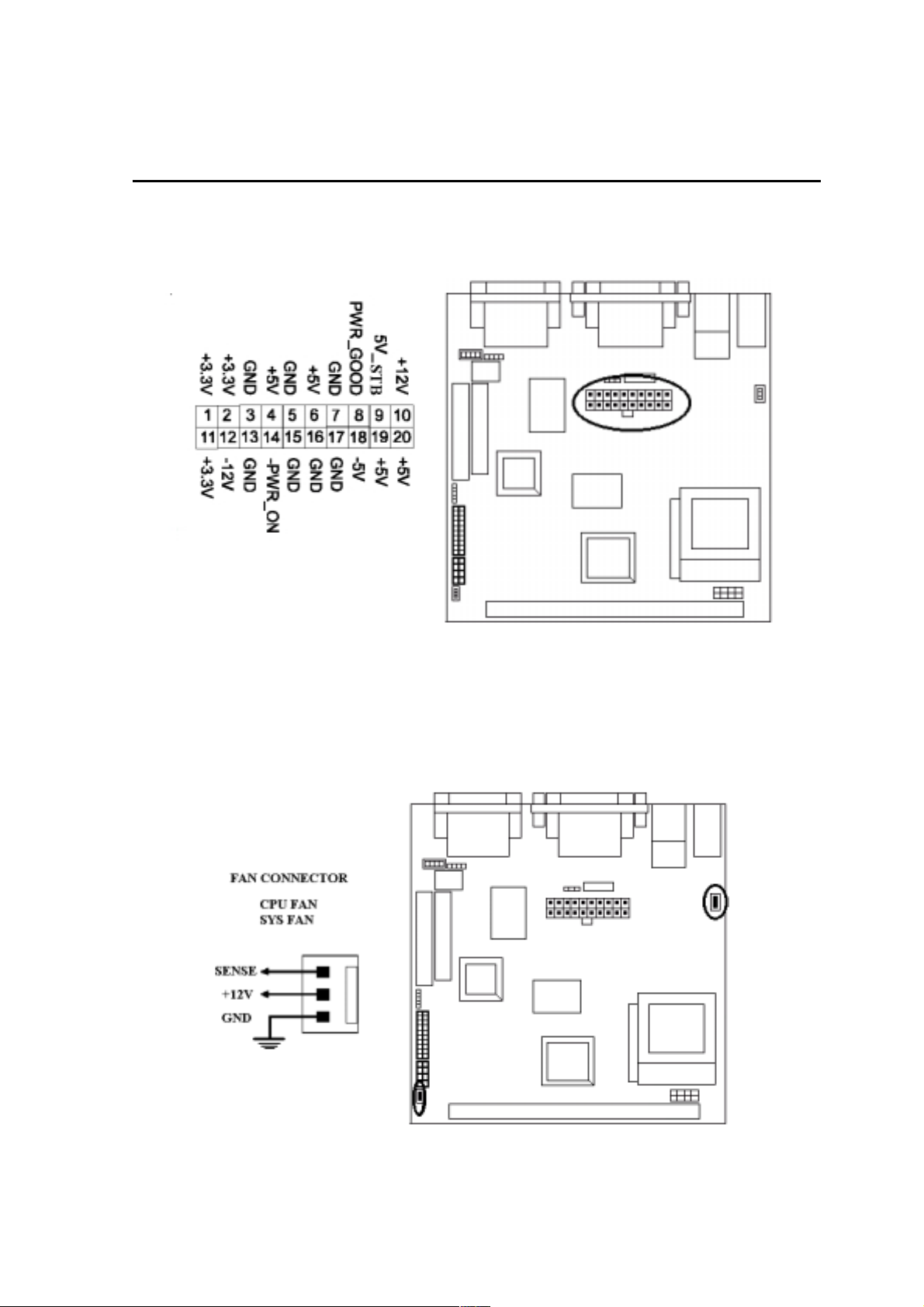
2. Power Connector
Connect the 20-pin ATX power supply cable to this power connector. Make sure
the right plug-in direction and the power supply is off before connecting or
disconnecting the power cable.
Remark: We suggest that users use 5 V STB and power source current
should be over 0.7A, otherwise it will affect system boot up.
2-7
Page 17
Hardware Installation
Remark: We suggest that users use 5 V STB and power source current
should be over 0.7A, otherwise it will affect system boot up.
ATX Power Connector
3. Fan Connector
Connect the CPU and System fan cables to the fan connectors shown below.
The fan connectors are marked as:
SYS FAN & CPU FAN on the motherboad.
2-8
Page 18
Hardware Installation
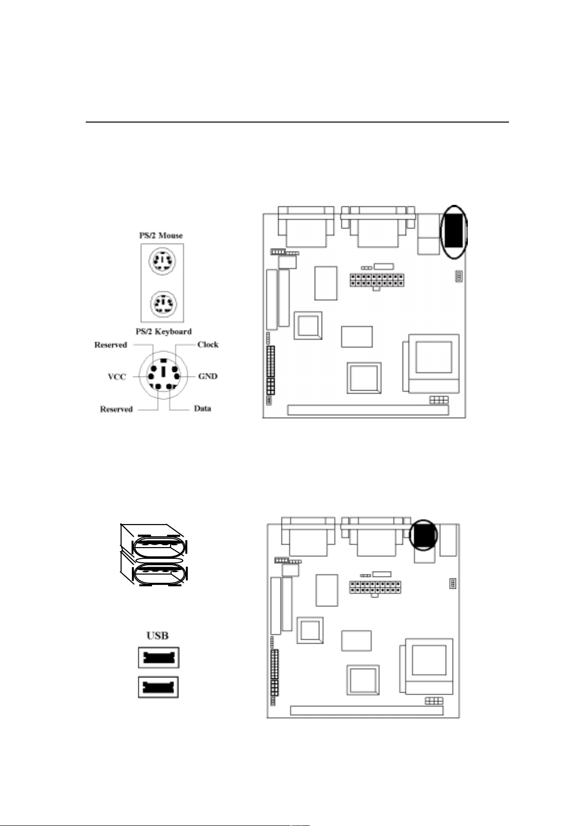
4. PS/2 Mouse and Keyboard Connector
Connect the PS/2 Mouse and Keyboard to the onboard 6-pin Mini-Din connector
shown as below.
5. USB Device Connector
Connect your USB device(s) to the onboard USB connector shown as below.
Top: USB1
Bottom: USB2
2-9
Page 19
Hardware Installation
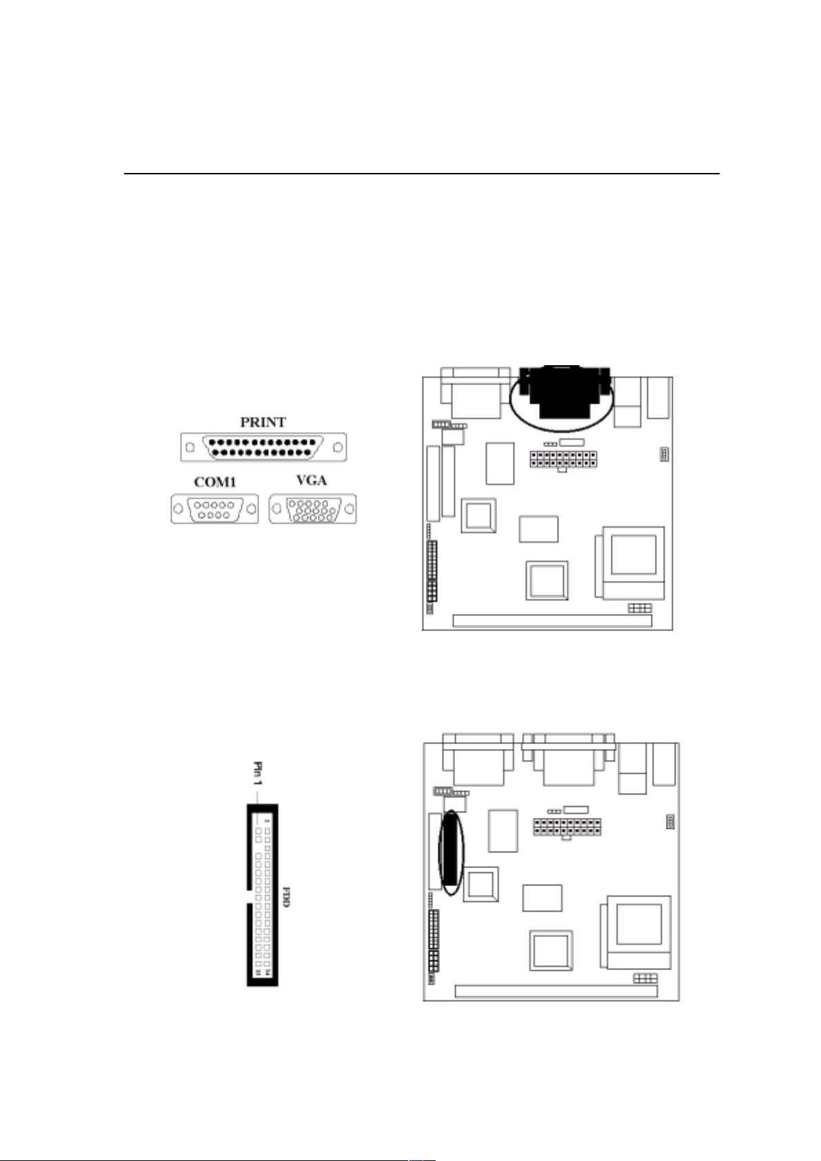
6. Serial Device COM1, VGA and Printer Connectors
Connector your serial device(s) to the onboard serial connectors marked as COM1.
Connect the 15-pins VGA Monitor Output marked as
or other VGA compatible devices. Connect your local
printer connector marked shown as below.
7. Floppy Drive Connector
VGA to your system monitor
Printer to the onboard 25-pin
Connect the floppy drive cable to the onboard 34-pin floppy drive connector
marked as
FDD.
2-10
Page 20
Hardware Installation
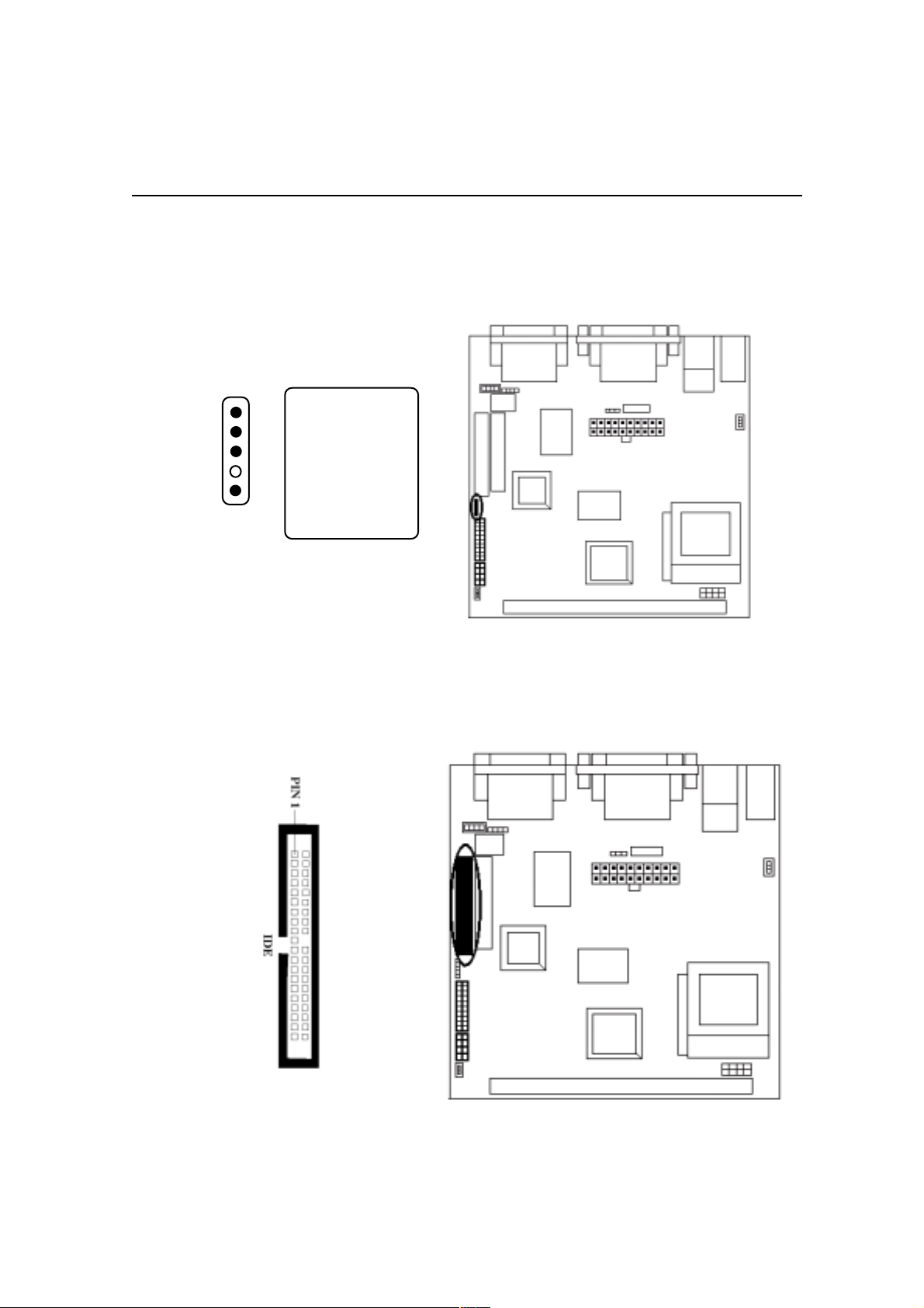
8. IrDA Connector
Connect your IR devices to the onboard IrDA connectors shown as below.
5
4
3
2
1
IrDA
Pin Description
5IRTX
4 GND
3 IRRX
2NC
1 +5V
9. IDE Hard Disk Connector
Connect your IDE devices to the onboard 40-pin IDE connectors marked as IDE1 .
2-11
Page 21
Hardware Installation
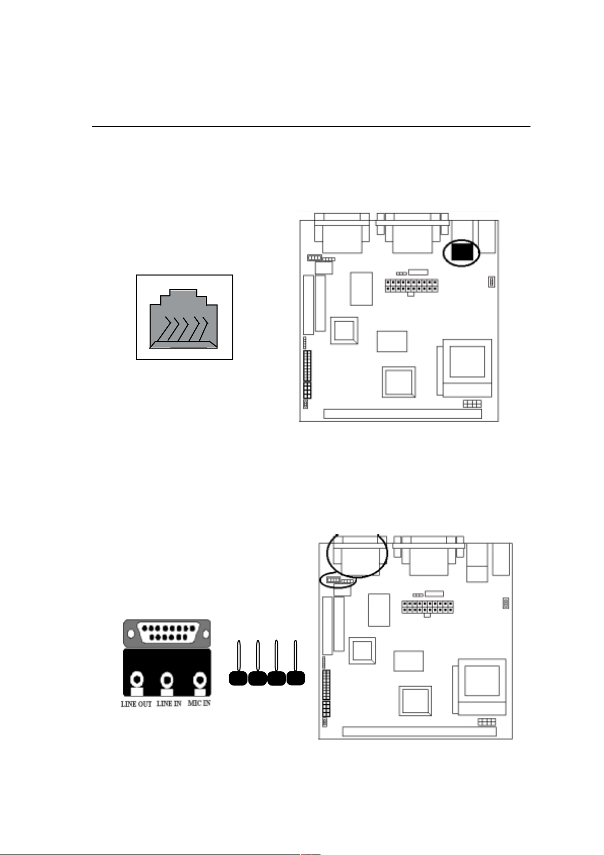
10. LAN Connector
Connect your LAN port to the onboard LAN connector shown as below.
LAN Connector
11. Game / Audio Connector and CD_IN Connectors
The 15-pin female Game/Audio connector allows you to connect game joystick or
game pads for playing games. Connect MIDI devices for playing or editing audio.
The CD connector onboard marked as
JOYSTICK
CD-IN
CON 2
CD-IN is for CD-ROM connection.
2-12
Page 22
Hardware Installation
System Memory InstallationSystem Memory Installation
System Memory Installation
System Memory InstallationSystem Memory Installation
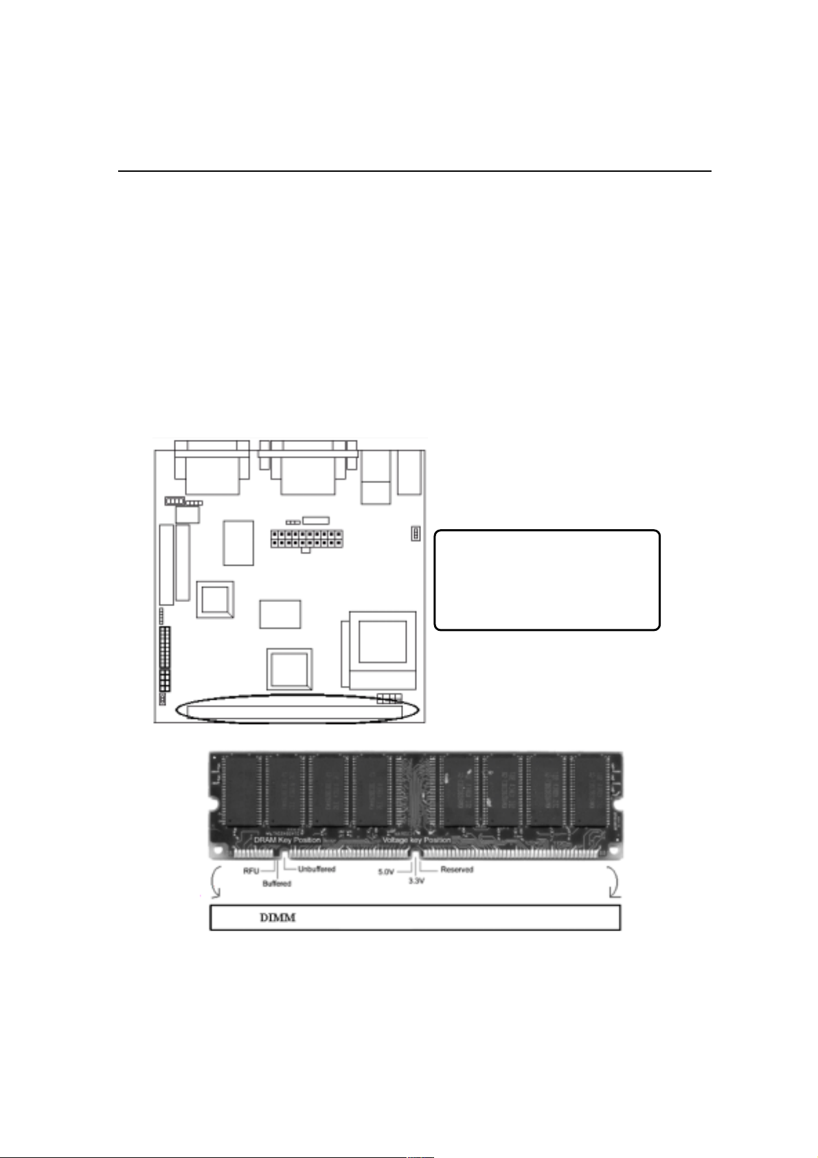
There is 1 piece 168-pin DIMM (Dual Inline Memory Module) socket on the
motherboard which support SDRAM and EDO DRAM memory.
♦ To ensure reliability, it is recommended to use PC 100 SDRAM for your high
clock SDRAM performance requirement.
♦ DIMM Sizes supported: 8MB, 16MB, 32MB, 64MB, 128MB, 256MB.
There are 1x168-pin DIMM slot
that allow you to install the system
memory max up to 256MB
SDRAM.
2-13
Page 23
Hardware Installation
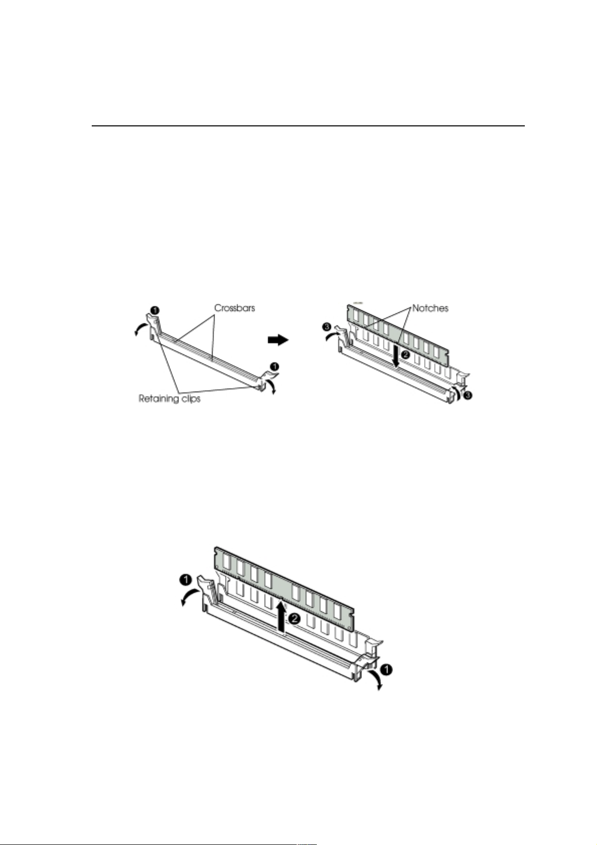
1 Install DIMM
1) Locate the DIMM socket on the motherboard.
2) Orient a DIMM to the socket so that the two notches in the DIMM connector are
aligned with the crossbars in the socket.
3) Press the DIMM straight into the socket until the retaining clips snap into place
around the ends of the DIMM.
2 Removing a Memory Module
To remove memory module, press the retaining clips outward simultaneously
until the DIMM disengages from the socket and then carefully remove the
DIMM from the socket.
2-14
Page 24
Chapter 3 CMOS Setup Utility
The rest of this manual is intended to guide you through the process of configuring
your system using Setup. While the BIOS is in control, the Setup program can be
activated by pressing the <Del>key during the POST (Power On Self-Test).If the
message disappears before you respond and you still wish to enter Setup, restart the
system to try again by turning it OFF then ON or pressing the RESET button on
the system case. You may also restart by simultaneously pressing <Ctrl>, <Alt>, and
<Delete> keys.
CMOS Setup Main MenuCMOS Setup Main Menu
CMOS Setup Main Menu
CMOS Setup Main MenuCMOS Setup Main Menu
Once you enter the BIOS setup utility, the Main Menu will appear on the screen. The
Main Menu allows you to select from several setup functions . the arrow keys to select
among the items and press <Enter> to accept and enter the submenu.
3-1
CMOS Setup Utility - Copyright (C) 1984-2000 Award Software
#$$Standard CMOS Features $ Load Fail-Safe Defaults
#$$Advanced BIOS Features Load Optimized Defaults
#$$Advanced Chipset Features Set Supervisor Password
#$$Integrated Peripherals Set User Password
$
$Power Management Setup
#
Esc : Quit
F10 : Save & Exit Setup
Abandon all datas
Save & Exit Setup
Exit Without Saving
: Select Item
!"# $
Page 25
CMOS Setup Utility
The main menu includes the following main setup categories, which defines basic
information about your system. Below are the keyboard function keys you can use under
the menu.
Menu function keys:
↑↑
↓↓
↑
↓
↑↑
↓↓
F1
F10
ENTER
ESC
←←
←
←←
: To Move around the screen. An item is highlighted if it is selected.
→→
→
→→
: Help.
: Save CMOS Changes & Exit.
: To select or enter a submenu.
: To quit the BIOS Setup Utility.
3-2
Page 26
CMOS Setup Utility
Standard CMOS SetupStandard CMOS Setup
Standard CMOS Setup
Standard CMOS SetupStandard CMOS Setup
The items in Standard CMOS Setup Menu are divided in 10 catagories. Each
catalogue includes one or more than one setup items. Use the keys to highlight
the item and then use the / <PgUp> / <PgDn> keys to select the value you
↑ ↓ ← →
want in each item.
CMOS Setup Utility - Copyright (C) 1984-2000 Award Software
Standard CMOS Features
Date (mm:dd:yy):
Time (hh:mm:ss):
!
IDE Primary Master
!
IDE Primary Slave
Drive A
Drive B
Video
Halt On
Base Memory
Extended Memor y
Tota l Mem ory
: Mo ve Enter: Select F5 : Previous Values +/-/PU/PD: Value F10: Save
!"#$
F6: Fail-safe de faults Esc:Exit F1: Gen eral Help F7 : Optimized Defaults
Fri, May 19 2000
16:19:20 Item H elp
Press Enter 3249MB
Press Enter None
1.44M. 3.5in
None
EGA / VGA
All, But Keyboa rd
640K
63488K
64512K
Menu Lev el
Change the da y, month, yea r
and century
!
Date & Time
To set the date and time, highlight the date area.Press /<PgUp>/ <PgDn> to set
↑ ↓ ← →
the current date. The date format is month: Jan. ~ Dec; date: 1 ~ 31; year: 1994 ~ 2079;
hour: 00 ~ 23; and second: 00 ~ 59.
# Hard Disks → IDE Primary Master
# Hard Disks
→ IDE Primary Slave
3-3
Page 27
CMOS Setup Utility
Press <Enter> to enter the submenu of detailed options, the following table shows the
IDE primary master submenu.
CMOS Setup Utility - Copyright (C) 1984-2000 Award Software
IDE Primary Master
IDE HDD Auto-Detection Press Enter Item Help
IDE Primary Master
Ac cess Mode
Capacity 3249M B
Cylinder
Head
Precomp
Landing Zone
Sector
: M ove Enter: Select
!"#$
F5 : Previous Values
Auto
Auto
6296
16
65535
6295
63
+/-/PU/PD: Value F10: Save
F6 : Fail-safe defaults
Menu Level
Change the day, month, year
and century
Esc:Exit F1 : Gener al H elp
F7 : Optimized Defaults
!
IDE HDD Auto-detection
Press Enter to auto - detect the HDD on the channel. If detection is successful, it fills
the remaining feilds on the menu.
IDE Primary Master
Selecting manual lets you set the remaining fields on the screen. Selects the type of
fixed disk. User Type will let you select the number of cylinders, heads, etc.
Note: Note:
Note: PRECOMP=65535 means NONE!
Note: Note:
The optional are: None, Auto (Default), Manual
The following options are selectable on ly
item is s e t t o ' Ma nua l':
Cylinder
Head
Precomp
Landing zone
Sect or
Min = 0
Max = 65535
Min = 0
Max = 255
Min = 0
Max = 65535
Min = 0
Max = 65535
Min = 0
Max = 255
if the 'IDE Primary Master'
Set the number of cylinders for this
hard di sk.
Set the number of read/write heads
Warni ng: Setting a value of 65535
means no hard disk
Number of sectors per track
3-4
Page 28

CMOS Setup Utility
Access Mode
Choose the access mode for this hard disk.
The optional are: Normal, LBA, Large, Auto (Default).
Capacity
Disk drive capacity (approximated). Note that this size is usually slightly greater than
the size of the formatted disk given by a disk checking program.
The optional are: Auto display your drive size.
Drive A / Drive B
Select the floppy drive type installed in your system. The available options for Drive A
and Drive B.
The optional are: 360K 5.25 in, 1.2M 5.25 in, 720K 3.5 in, 1.44M 3.5 in(Drive A
default), 2.88M 3.5 in and NONE (Drive B default).
Video
Select the video display card type installed in your system.
The optional are: EGA/VGA (Default), CGA 40, CGA 80 and Mono.
Halt On
This item defines the operation of the system POST (Power On Self-Test). You can use
this item to select which kind of errors will cause the system to halt during POST.
The optional are: All Errors, No Errors, All But Keyboard (Default), All But Diskette
and All But Disk / Key
3-5
Page 29

Advanced BIOS FeaturesAdvanced BIOS Features
Advanced BIOS Features
Advanced BIOS FeaturesAdvanced BIOS Features
CMOS Setup Utility - Copyright (C) 1984-2000 Award Software
Advanced BIOS Features
CMOS Setup Utility
Virus Warn ing
CPU Internal Cache
External C ach e
CPU L2 Cache ECC Checking
Quick Power On Self Test
First Boot Device
Seco nd Boot Device
Third Boot device
Boot other device
Swap Floppy Drive
Boot Up Floppy S eek
Boot Up Numlock Status
Gate A 20 Optio n
Typ ema tic Rate S ett in g
x Typemati c Ra te (C h ar s/Se c)
x Typ em a tic De la y (M s ec )
Se curi ty O ptio n
OS Select For DRAM > 64MB
Report No FDD For WIN 95
: Move Enter: Select F5 : Previous Values +/-/PU/PD: Value F10: Save
!"#$
F6 : F ail-safe defaults Esc:Exit F1: General Help F7 : Optimized Defaults
Disabled
Enabled
Enabled
Enabled
Disabled
Floppy
HDD-0
LS120
Enabled
Disabled
Enabled
On
Fast
Disabled
6
250
Setup
Non-O S2
No
Item Help
Menu Level
Allows you to choose the
VIRUS warning feature for
IDE Hard D isk bo ot sector
protection. If this function is
enab led and someon e
attempt to write data into
this area, BIOS will show a
warning message on scree n
and alarm beep.
!
Virus Warning
If this function enabled and someone attempt to write data into this area, BIOS will auto-
matically show a warming message on screen and alarm beep.
The optional are: Enabled, Disabled (Default)
CPU Internal / External cache
These two items controls Enable / Disable the CPU internal / external cache.
The optional are: Enabled (Default), Disabled
CPU L2 Cache ECC Checking
This item allows you to enable / disable CPU L2 Cache ECC Checking.
The optional are: Enabled (Default), Disabled
3-6
Page 30

CMOS Setup Utility
Quick Power On Self Test
This item speeds up Power On Self Test (POST) after you power up the computer. If it
is set to Enable, BIOS will shorten or skip some check items during POST.
The optional are: Enabled, Disabled (Default)
First / Second / Third Boot Device
The BIOS attempts to load the operating system from the devices in the sequence
selected in these items.
The optional are: Floppy (First Default), HDD-0(Second Default), LS 120 (Third
Default), HDD-1/2/3, ZIP 100, SCSI, CDROM, LAN.
Boot Other Device
The BIOS attempts to load the operating system from the other device in the sequence
selected in these items.
The optional are: Enabled (Default), Disabled
Swap Floppy Drive
If the system has two floppy drives, choose enable to assign physical drive B to logical
drive A and vice-versa.
The optional are: Enabled, Disabled (Default)
Boot Up Floppy Seek
Seeks disk drives during boot up.
The optional are: Enabled (Default), Disabled
Boot Up NumLock Status
Selects power on state for NumLock.
The optional are: Off, On (Default)
Gate A20 Option
Normal-a pin in the keyboard controller controls Gate A20. Fast lets chipset control
Gate A20.
The optional are: Normal, Fast (Default)
3-7
Page 31

CMOS Setup Utility
Typematic Rate Setting
Keystrokes repeat at a rate determined by the keyboard controller, when enabled, the
typematic rate and typematic delay can be selected.
The optional are: Enabled, Disabled(Default)
Typematic Rate (Chars/Sec)
Sets the number of times a second to repeat a key stroke when you hold the key down.
The optional are: 6 (Default), 8, 10, 12, 15, 20, 24, 30
Typematic Delay (Msec)
Select the delay time after the key is held down before it begins to repeat the key
strokes.
The optional are: 250 (Default), 750, 1000
Security option
Select whether the password is required every time when you enter setup.
Setup -- The system will boot up.
System -- The system will not boot and access to setup will be denied if the correct
password is not entered at the prompt.
The optional are: Setup (Default), System
OS Select for DRAM > 64MB
Select OS2 only if you are running OS/2 operating system with greater than 64MB of
RAM on the system.
The optional are: Non-OS/2 (Default), OS/2
Report No FDD for WIN 95
Whether report no FDD for WIN 95 or not.
The optional are: Yes, No (Default)
3-8
Page 32

CMOS Setup Utility
Advanced Chipset FeaturesAdvanced Chipset Features
Advanced Chipset Features
Advanced Chipset FeaturesAdvanced Chipset Features
This item allows you to configure the system based on the specific features of
the chipset. This chipset manages bus speed and access to system memory
recources, and external cache. It must be stated that these items should never
need to be altered.The default settings have been chosen because they provide
you the best operating conditions for your system. The only time you might
consider making any changes if you discovered that the datas were being lost
while control your system.
CMOS Setup Utility - Copyright (C) 1984-2000 Award Software
Advanced Chipset Features
SDRAM CAS Latency Time
SDRAM Cycle Time Tras/Trc
SDRAM RAS-to-CAS Delay
SDRAM RAS Precharge Time
System BIOS Cacheable
Video BIOS Cacheable
Memory Hol e At 15M-16M
CPU Latency Timer
Dela yed Transaction
On-Chip Video Window Size
Use VGA BI OS in VBU Bloc k
!"#$
: Move Enter: Select F5 : Previous Values +/-/PU/PD: Value F10: Save
F6 : Fail-sa fe defaults Esc:Exit F1: General Help F7 : Opt imized Defaults
3
6/8
3
3
Disabled
Disabled
Disabled
Disabled
Enabled
64MB
Enabled
Item H elp
Menu Level
!
SDRAM CAS Latency Time
When synchronous DRAM is installed, the number of clock cycles of CAS latency
depends on the DRAM timing.
The optional are: 3(Default), 2
SDRAM Cycle Time Tras/Trc
Select the number of SCLKs for an access.
The optional are: 6/8 (Default), 5/7
3-9
Page 33

CMOS Setup Utility
SDRAM RAS-to-CAS Delay
When synchronous DRAM is installed in the system, this field lets you insert a timing
delay between the as CAS and RAS strobe signals, used DRAM is written to, read
from,or refreshed.
The optional are: 3(Default), 2
SDRAM RAS Precharge Time
If an insufficient number of cycles is alllowed for the RAS to accumulate its charge
before DRAM refresh, the refresh may be incomplete and the DRAM may fail to
retain data.
The optional are: 3(Default), 2
System BIOS Cacheable
Selecting Enabled allows caching of the system BIOS ROM at F0000h-FFFFFh, resulting
in better system performance.
The optional are: Enabled, Disabled(Default)
Video BIOS Cacheable
Select Enabled allows caching of the video BIOS, resulting in better system perfor-
mance.
The optional are: Enabled, Disabled(Default)
Memory Hole At 15M - 16M
When this area is reserved, it cannot be cached. The user information of peripheral that
need to use this area of system memory usually discusses their memory requirements.
The optional are: Enabled, Disabled(Default)
CPU Latency Timer
This option allows you to Enabled/Disabled CPU latency Timer.
The optional are: Enabled, Disabled(Default)
Delayed Transaction
Select Enabled to support compliance with PCI specification version 2.1.
The optional are: Enabled(Default), Disabled
3-10
Page 34

CMOS Setup Utility
Delayed Transaction
Select Enabled to support compliance with PCI specification version 2.1.
The optional are: Enabled(Default), Disabled
On-chip Video Window Size
Select the on-chip video window size for VGA drive use.
The optional are: Enabled, 32MB, 64MB(Default)
Use VGA BIOS in VBU Block
Let you determine whether use VGA BIOS in VBU Block or not.
The optional are: Enabled (Default), Disabled
Integrated PeripheralsIntegrated Peripherals
Integrated Peripherals
Integrated PeripheralsIntegrated Peripherals
CMOS Setup Utility - Copyright (C) 1984-2000 Award Software
Integrated Peripherals
On-Chip IDE
IDE Master PIO
IDE S lave P IO
IDE Master UDMA
IDE S lave U DMA
USB Controller
USB Keyboard Support
AC97 Audio
IDE HDD Block Mode
KBC input clock
Power On function
KB Power ON P assw ord
Hot Key Power On
Onboard FDC Controller
Onboard Serial Port1
UART Mode Select
UR2 Duplex mode
Onboard P arallel Port
Parallel Port M ode
ECP Mode Use DMA
Game Port Address
Midi Port Address
Midi Port IRQ
: Move E nter: Selec t F5 : Previous Values +/-/PU /PD: Value F10: Save
!"# $
F6 : Fail-safe defaults Esc:Exit F1: General Help F7 : Optimized Defaults
Enabled
Auto
Auto
Auto
Auto
Enabled
Disabled
Auto
Enabled
8MHz
Enter
Ctrl-F1
Enabled
3F8/IR Q4
Half
3
201
330
10
Item He lp
Menu Level
!
3-11
Page 35

CMOS Setup Utility
On-Chip IDE
The integrated peripheral controller contains an IDE interface with support IDE
channel. Select Enabled to activate the channel.
The optional are: Enabled (Default), Disabled
IDE Master / Slave PIO
The two IDE PIO fields let you set a PIO mode for each of the two IDE devices that
IDE face support onboard. Mode 0 through 4 provide successively increased
performance. In Auto mode, the system automatically determines the best mode for
each device.
The optional are: Auto (Default), Mode 0, Mode 1, Mode 2, Mode3, Mode 4
IDE Master / Slave UDMA
If your hard drive and system software both support Ultra DMA 33, select Auto to
enable BIOS support.
The optional are: Auto(Default), Disabled
USB Controller
Select Enabled if your system contains a Universal Seria Bus (USB) controller and
you have a USB peripheral.
The optional are: Enabled (Default), Disabled
USB Keyboard Support
Select Enabled if your system contains a universal Serial Bus (USB) controller and
you have a USB keyboard.
The optional are: Enabled, Disabled(Default)
AC 97 Audio
This item allows you to decide to enable/ disable the 810 chipset family to support
AC 97 audio.
The optional are: Auto (Default), Disabled
3-12
Page 36

CMOS Setup Utility
IDE HDD Block Mode
If your IDE hard drive supports block mode (most new drives do), select Enabled
for automatic detection of the optimal number of block read / write per sector the drive
can support.
The optional are: Enabled(Default), Disabled
KBC input clock
Set the KBC input clock.
The optional are: 8MHz (Default), 12MHz
POWER ON Function
Set the power on function mode for power on.
The optional are: Password, Hot Key, Mouse Move / Click, Any Key(Default),
BUTTON ONLY, Keyboard 98
KB Power ON Password
If Power On Function is set Password, this option let you set KB Power On Password.
Press <Enter> and enter your password.
Hot Key Power ON
This option let you choose Power ON Key from <Ctrl-F1> to <Ctrl-F12>.
The optional are: Ctrl-F1(Default), Ctrl-F12
Onboard FDC Controller
Select Enabled if your system has a floppy disk controller (FDC) installed on the
system board and you wish to use it. If you install an add-in FDC or the system has no
floppy drive, select Disabled in this field.
The optional are: Enabled(Default), Disabled
3-13
Page 37

CMOS Setup Utility
Onboard Serial Port
Select a logical COM port name and matching address for the serial port. Select an
address and corresponding interrut for serial port.
The optional are: Auto, Disabled, 3F8 / IRQ4(Port 1 Default), 2F8 / IRQ3(Port 2
Default), 3E8 / IRQ4, 2E8 / IRQ3
UART Mode Select
Let you choose UART Mode.
The optional are: Normal(Default), IrDA, ASKIR, SCR
Onboard Parallel Port
Select a logical LPT port address and corresponding interrupt for the physical
parallel port.
The optional are: 378/IRQ7(Default), 278/IRQ5, 3BC/IRQ7, Disabled
Parallel Port Mode
Select an operating mode for the on board parallel (printer) port.
The optional are: SPP(Default), EPP, ECP, ECP+EPP
Game Port Address
Select an address for game port.
The optional are: Disabled, 201(Default), 209
Midi Port Address
Select an address for Midi Port.
The optional are: Disabled, 330 (Default), 300
Midi Port IRQ
Select a corresponding interrupt for Midi Port.
The optional are: 5, 10(Default)
3-14
Page 38

CMOS Setup Utility
Power Management SetupPower Management Setup
Power Management Setup
Power Management SetupPower Management Setup
The Power Management Setup allows you to configure your system effectively
save energy while operating in a manner consistent with your own style of com-
puter use.
CMOS Setup Utility - Copyright (C) 1984-2000 Award Software
Power Management Setup
Powe r Manage ment
Video Off Metho d
Video Off In Suspend
Susp end Type
Susp end Mode
HDD Power Down
Soft-Off by PWR-BTTN
Wake On by Ring
** Reload Global Timer Events **
Prima ry IDE 0
Prima ry IDE 1
FDD, COM, LPT Port
PCI PIRQ [A-D]#
!"#$: Move Enter: Select F5 : Previous Values +/-/PU/PD: Value F10: Save
F6 : Fail-safe defaults Esc:Exit F1: General Help F7 : Optimized Defaults
User Define
DPMS
Ye s
Stop Grant
Disabled
Disabled
Instant-Off
Enabled
Disabled
Disabled
Disabled
Disabled
Item Help
Menu Level
!
Power Management
This category allows you to select the type(or degree) of power directly related to the
following modes: HDD Power Down; Doze Mode; Suspend Mode. User Define allows
you to set each mode individually. When not disabled, each of the ranges are from 1min.
to 1hr. except for HDD Power Down which ranges from 1min. to 15min. and disable.
The optional are: User Define(Default), Min Saving, Max Saving
Video Off Method
Determines the manner in which the monitor is blanded. System turns off vertical and
horizontal synchronization ports and writes blanks to the video buffer. Select this option
if your monitor supports.System only writes blanks to the video buffer.
The optional are: V/H SYNC+Blank, DPMS (Default), Blank Screen
3-15
Page 39

CMOS Setup Utility
Video Off In Suspend
Setup whether video off in suspend or not.
The optional are: Yes (Default), No
Suspend Type
This item lets you select a method of global system suspend.
The optional are: Stop Grant(Default), PwrOn Suspend
Suspend Mode
After the selected period of system inactivity, all devices except the CPU shut off.
The optional are: 1/2/4/8/12/20/30/40Min, 1 Hour, Disabled (Default)
HDD Power Down
After the selected period of drive inactivity, the hard disk drive powers down while
all other devices remain active.
The optional are: 1/2/3/4/5/6/7/8/9/10/11/12/13/14/15 Min, Disabled(Default)
Soft-Off by PWR-BTTN
When Enabled, turning the system off with the on/off button places the system in a
very low-power-usage state, with only enough circuitry receiving power to detect
power button activity or Resume by Ring activity.
The optional are: Instant-Off (Default), Delay 4 Sec.
Wake On by Ring
Setup whether Wake on by ring or not.
The optional are: Enabled(Default), Disabled
Primary IDE 0 / IDE 1
This option allows you determine whether enable Primary IDE 0/IDE 1 or not.
The optional are: Enabled, Disabled(Default)
3-16
Page 40
CMOS Setup Utility
FDD,COM,LPT Port
This option allows you set whether enable FDD, COM, LPT Port or not.
The optional are: Enabled, Disabled(Default)
PCI PIRQ[A-D]#
This option lets you set PCI PIRQ [A-D]#.
The optional are: Enabled, Disabled(Default)
Load Fail-Safe DefaultsLoad Fail-Safe Defaults
Load Fail-Safe Defaults
Load Fail-Safe DefaultsLoad Fail-Safe Defaults
This option allows you load Fail-Safe Defaults settings. To load setup default, press
<Y> key to confirm the operation when you see the below display.
CMOS Setup Utility - Copyright (C) 1984-2000 Award Software
#$$Stan dard C MOS Feature s #$$Freq uency / Voltage Contr ol
#$$Adv anced BIOS Feature s L oad F ail-Safe Defau lts
#$$Adv anced Chipset Featu res Load O ptimiz ed Def aults
#$$Inte grated Peripherals Set Sup ervisor Passord
#$$Pow er Ma nagement Se tup Set Use r Passo word
#$$PnP / PCI Configuration S ave & Exit S etup
#$$PC Health Status Exit Withou t Savin g
Esc : Quit
F10 : S ave & Exit Setup
Load Fail - Safe Defaults (Y / N)? N
: Select I tem
!"#$
Abandon a ll datas
3-17
Page 41
CMOS Setup Utility
Load Optimized DefaultsLoad Optimized Defaults
Load Optimized Defaults
Load Optimized DefaultsLoad Optimized Defaults
This option allows you load Optimized Defaults settings to optimize your system.
To load optimized default, press <Y> key to confirm the operation when you see
the below display.
CMOS Setup Utility - Copyright (C) 1984-2000 Award Software
#$$Standard CMOS Features #$$Frequency / Voltage Control
#$$Advanced BIOS Features Load Fail-Safe Defaults
#$$Advanced Chipset Features Load Optimized Defaults
#$$Integrated Peripherals Set Supervisor Passord
#$$Power Management Setup Set User Passoword
#$$PnP / PCI Configuration Save & Exit Setup
Load Optimized Defaults (Y / N)?
#$$PC Health Status Exit Without Saving
: Select Item
Esc : Quit
F10 : Save & Exit Setup
Abandon all datas
!"#$
3-18
Page 42

CMOS Setup Utility
Set Supervisor / User PasswordSet Supervisor / User Password
Set Supervisor / User Password
Set Supervisor / User PasswordSet Supervisor / User Password
Password prevents unauthorized use of your computer. If you set a password, the
system prompts for the correct password before boot or access to setup. The main
difference between Supervisor Password and User Password is the privilege. Be-
cause Supervisor Password allows you to modify all CMOS setup but User pass-
word only some of them.
Their steps all as follows:
1. Highlight the item Set Supervisor Password / Set User Password on the main
menu and press ENTER.
2. The password dialog box will appear.
3. If you are installing a new password, carefully type in the password. Press
ENTER after you have typed in the password. If you are deleting a password
that is already installed just press ENTER when the password dialog box appears.
4. The system will ask you to confirm the new password by asking you to type it in
a second time. Carefully type the password again and press ENTER, or just press
ENTER if you are deleting a password that is already installed.
5. If you typed the password correctly, the password will be installed.
[NOTE]
If you forget your password, or you want to cancel your password, you can do the stepsIf you forget your password, or you want to cancel your password, you can do the steps
If you forget your password, or you want to cancel your password, you can do the steps
If you forget your password, or you want to cancel your password, you can do the stepsIf you forget your password, or you want to cancel your password, you can do the steps
as the following:as the following:
as the following:
as the following:as the following:
(1) Password forgotten:
i. Turn off the system.
ii. Short JP3 at Pin 2-3 for a few seconds to clear CMOS.
iii. Set the JP3 back to Pin 1-2.
iv. Power on the system.
(2) Clear Password:
Clear your password by key in the password you installed
3-19
before, then go to password setting to press ENTER twice.
Page 43

CMOS Setup Utility
Save & Exit SetupSave & Exit Setup
Save & Exit Setup
Save & Exit SetupSave & Exit Setup
Highlight this item and press ENTER to save the changes that you have made
in the setup utility and exit the setup program. When the Save and Exit dialog
box appears, press <Y> to save and exit, or press <N> to return to the setup
main menu.
Exit WExit W
Exit W
Exit WExit W
Use this option to exit setup utility without saving the CMOS value changes.
ithout Savingithout Saving
ithout Saving
ithout Savingithout Saving
3-20
Page 44
Chapter 4 Software Utility
The support software for this motherboard is supplied in a CD. All the support programs
are stored in separate folders, so you can find the program you need easily enough. We
recomend you to choose the program which you need most, it will assist your computer
system to high performance.
Installing InterfaceInstalling Interface
Installing Interface
Installing InterfaceInstalling Interface
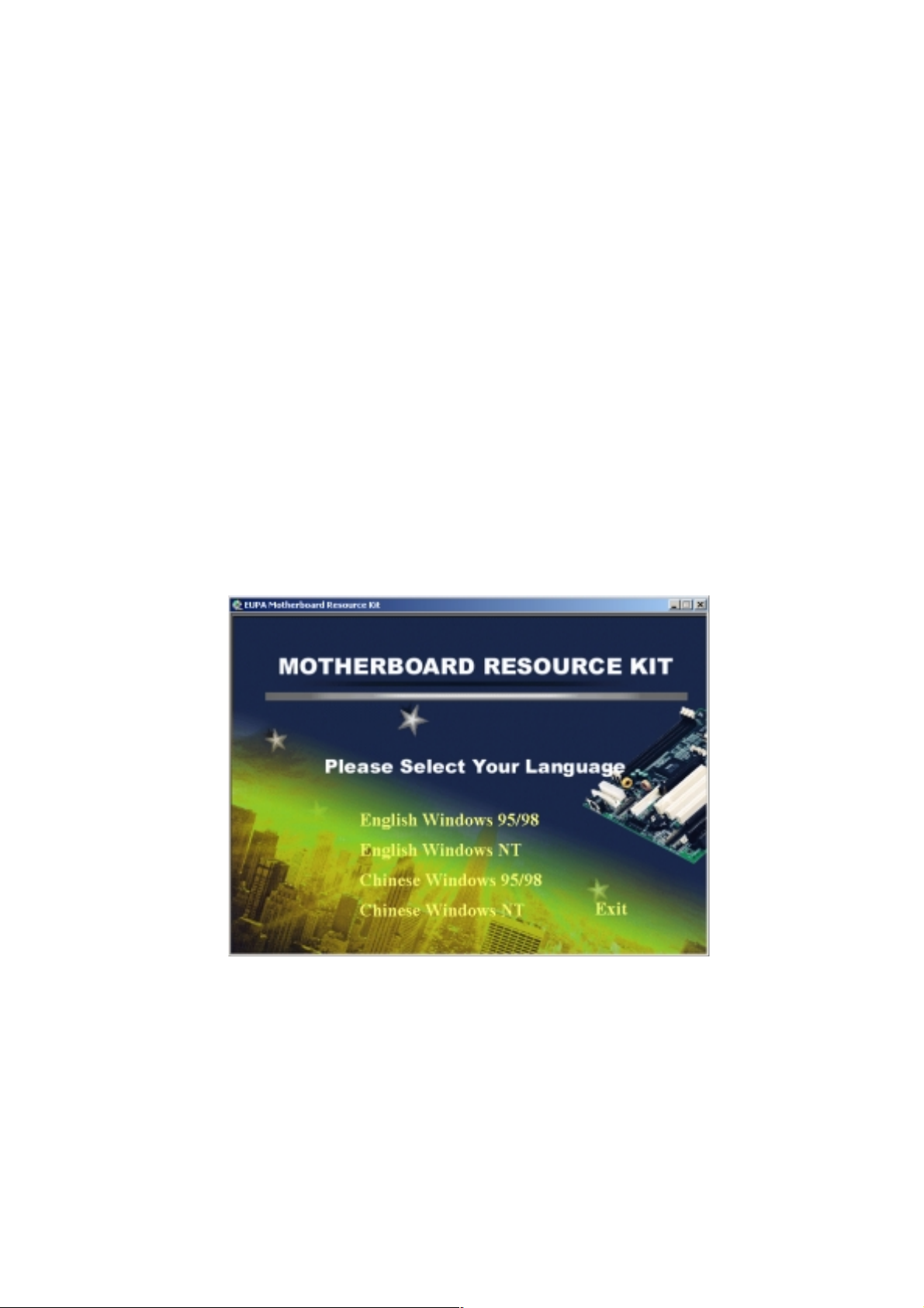
After you insert CD driver, it runs automaticly and appear the interface as below:
Choose the language and interface you need.
4-1
Page 45
Software Utility
Installing Driver Location:
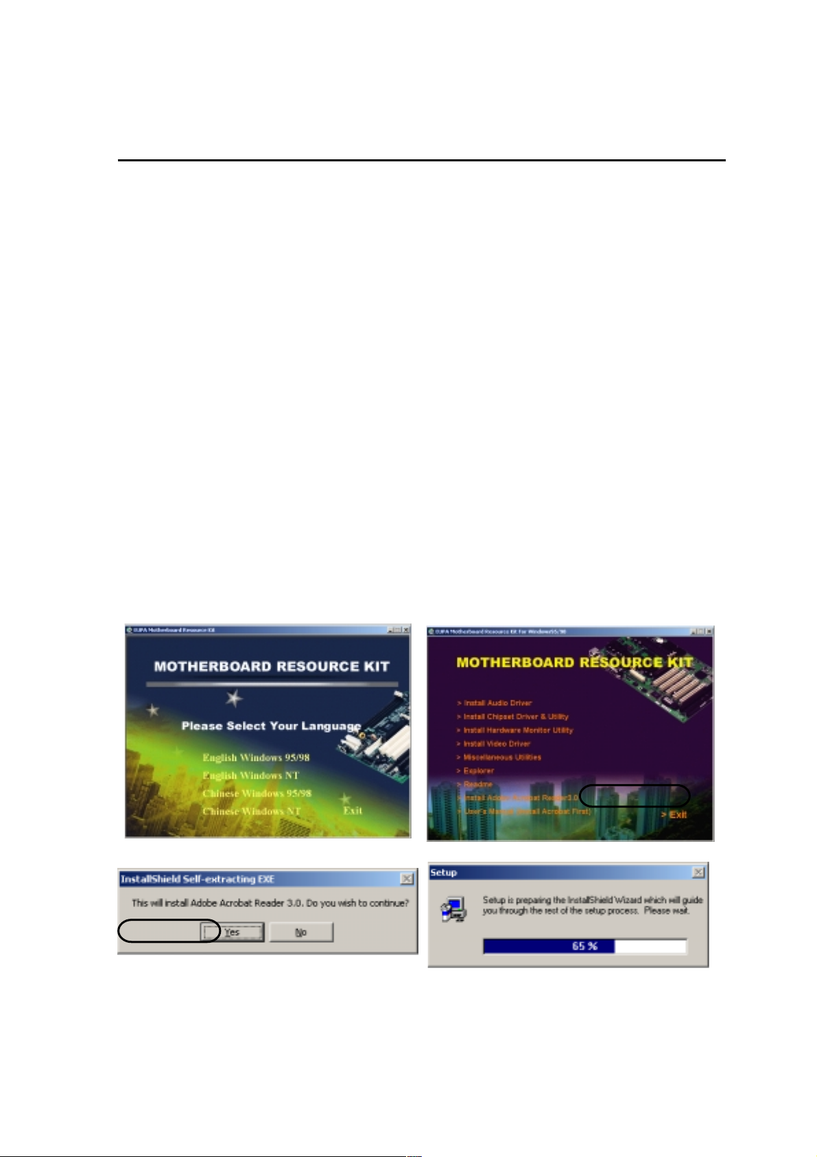
Insert CD Driver to the CD-ROM, driver runs by itself, and appear the following
interface, please refer to the procedure, then finish installing.
following Installing Driver
:
ITZV6 provides you the
Intel Video Driver Location : /VGA DRIVER
Intel 810 Chipset Driver Location: /CHIPSET
IDE DMA66 Driver Location: /IDE
Audio Driver Location: /AUDIO
LAN Driver Location: /LAN
Installing ADOBE Acrobat Read Driver
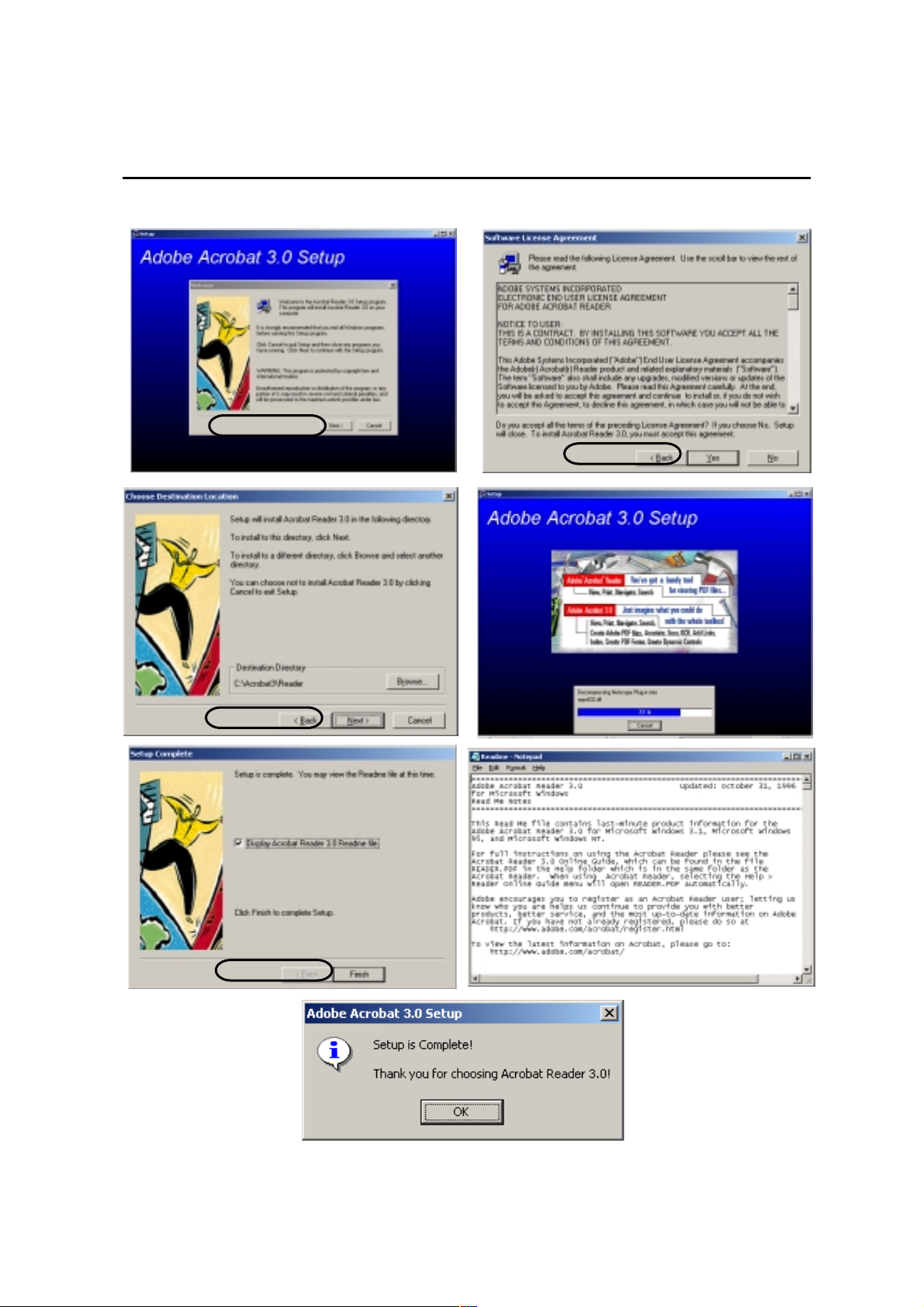
Insert CD Driver to the CD-ROM, driver runs by itself, and appear the following interface, please refer to the procedure, then finish installing.
(2)Click here
""
"
""
!(1) Click here
4-2
Page 46
Software Utility
(3)Click here
(5)Click here
""
"
""
""
"
""
(4)Click here
""
"
""
4-3
(7)Click here
""
"
""
Page 47

This Page Is Left For Note
 Loading...