

Page 1

QUICK
START GUIDE
Video Doorbell 2K (Battery-Powered) Set
Anker Innovations Limited. All rights reserved.
Security Logo
United States and other countries. All other trademarks are the property of
their respective owners.
51005002012 V01
are trademarks of Anker Innovations Limited, registered in the
eufy Security and eufy
Page 2

TABLE OF
English 01
Deutsch 30
Español 56
Français 82
Italiano 108
Nederlands 134
ةيِبَرَعل
160
CONTENTS
What’s Included
Product Overview
How The System Works
Connecting The Homebase
Setting Up The System
Determining The Power Option
Finding A Mounting Spot
02
04
06
07
08
09
11
Mounting The Bracket
13
Mounting The Doorbell
16
Detaching The Doorbell
17
Recharging The Doorbell
18
Powering The Doorbell With Existing
Doorbell Wires
19
Notice
27
Customer Service
30
English
01
Page 3
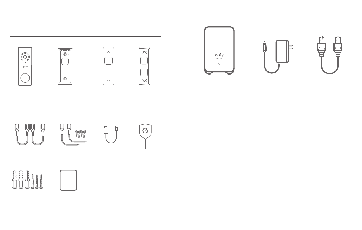
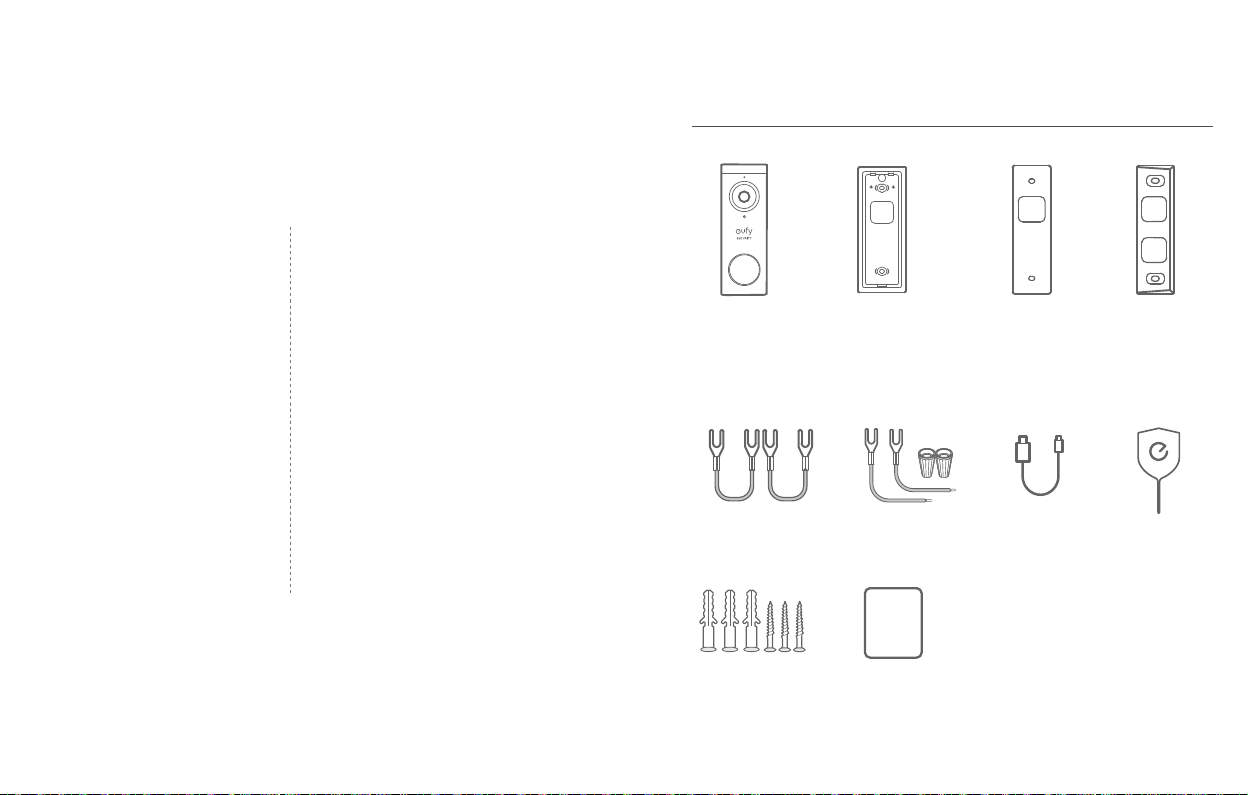
WHAT’S INCLUDED
QSG
For Video Doorbell Installation
For HomeBase 2 Installation
Model: HomeBase 2 Power Adapter for
Video Doorbell 2K
(Battery-Powered)
Model: T8210
FCC ID: 2AOKB-T8210
IC: 23451-T8210
Jumper for Original
Chime (Optional)
Screw Packs (Spare
screws and anchors are
included)
English English
02
Mounting Bracket
Extension Wires and
Wire Nuts (Optional)
Quick Start Guide
Screw Hole Positioning
Card
USB Charging
Cable
15° Mounting Wedge
(Optional)
Doorbell Detaching
Pin
FCC ID: 2AOKB-T8010
IC: 23451-T8010
Power plug may vary in different regions.
Note:
HomeBase 2
Ethernet Cable for
HomeBase 2
03
Page 4
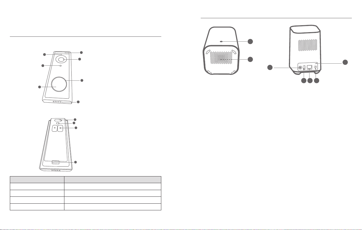
PRODUCT OVERVIEW
Video Doorbell (Battery Powered)
Front view:
2
4
6
Rear View:
Operation How-to
Power on Press and release the SYNC button
Add doorbell to HomeBase Press and hold the SYNC button until you hear a beep
Power off the doorbell Quick-press the SYNC button 5 times in 3 seconds.
Reset the doorbell Press and hold the SYNC button for 10 seconds.
1
3
1. Motion Sensor
2. Microphone
3. Camera Lens
4. Ambient Light Sensor
5. LED Ring
5
6. Doorbell Button
7. Speaker
7
1
2
3
1. Micro USB Charging Port
2. SYNC/RESET Button
3. Power Terminals for Existing
Doorbell Wire (Optional)
4. Detaching Mechanism
4
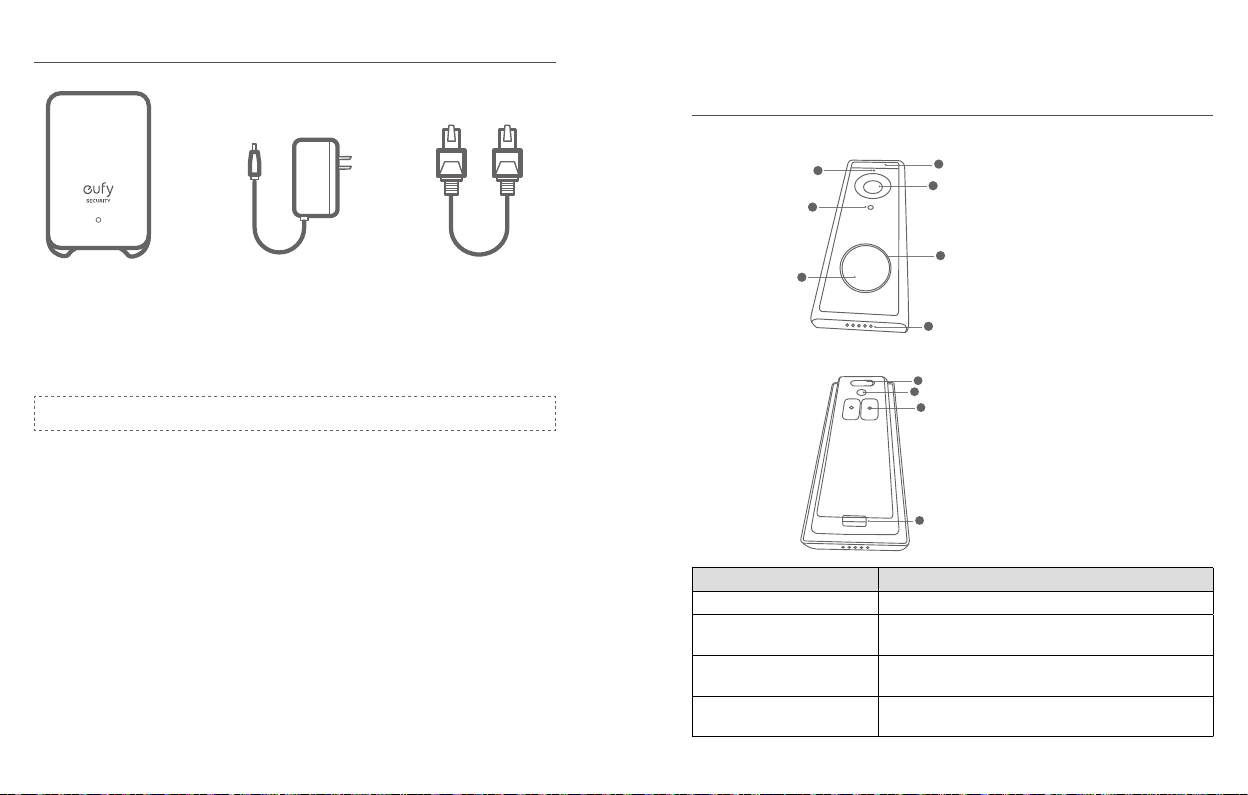
Video Doorbell (Battery Powered)
1
2
3
1. Status LED
2. Speaker
3. Power port
4. USB port
5. Ethernet port
6. SYNC/ALARM OFF button
7. Reset button
7
4 5 6
English English
04
05
Page 5
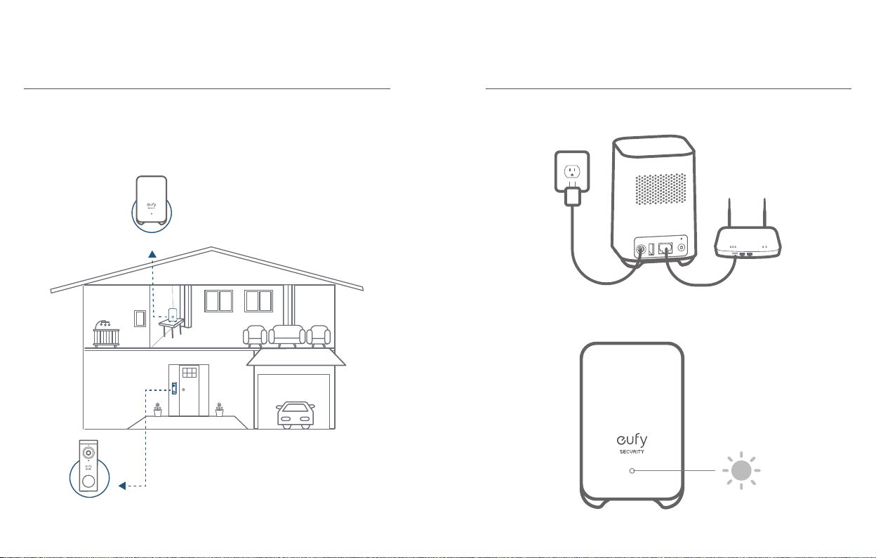
HOW THE SYSTEM WORKS
STEP 1 CONNECTING THE HOMEBASE
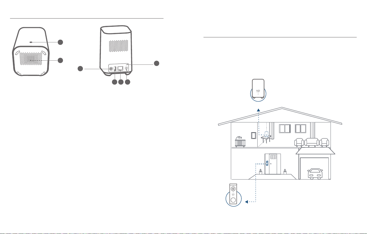
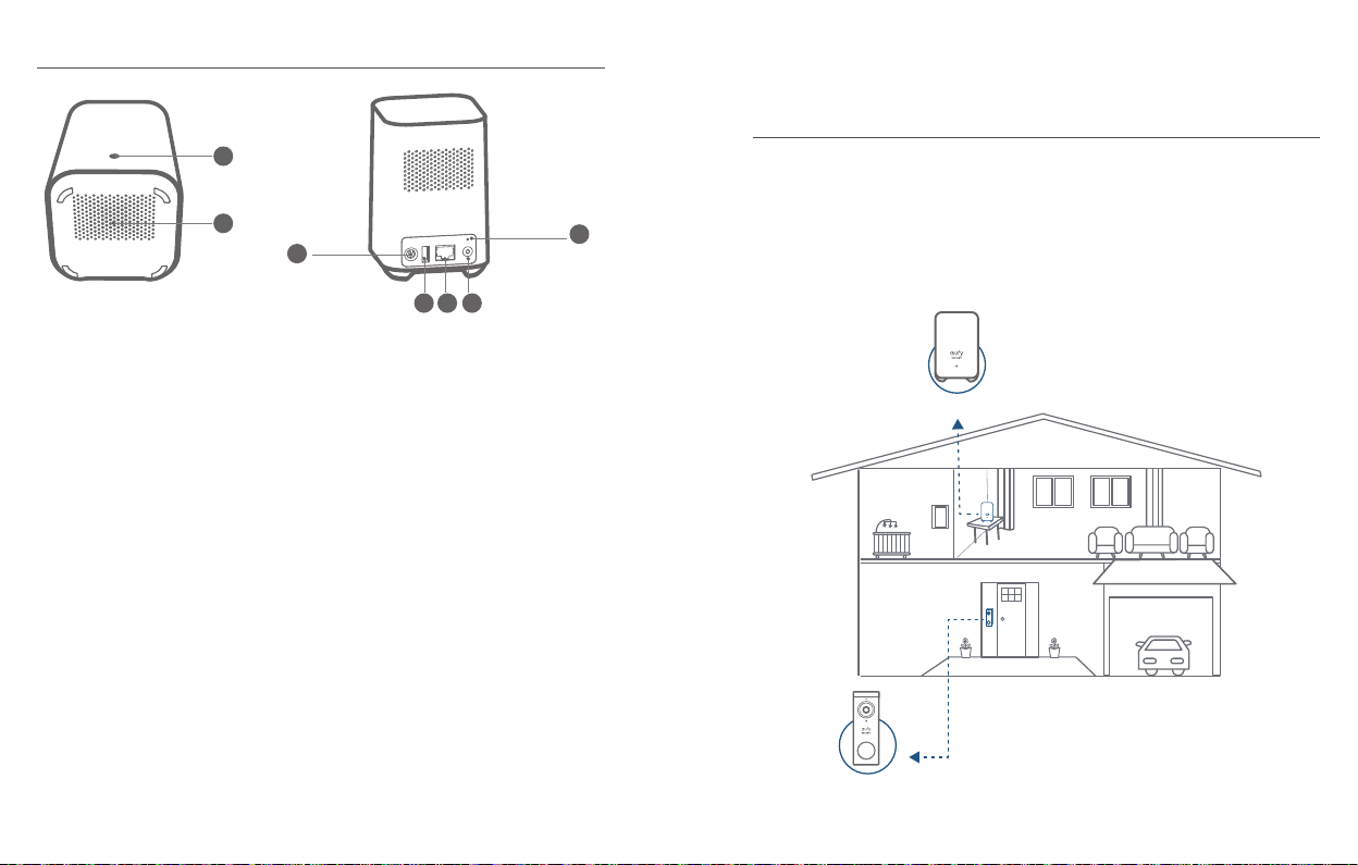
How the System Works
The video doorbell system includes 2 parts. One is the video doorbell at your door.
The other is the HomeBase in your house.
The video doorbell detects motion at your porch and allows you to answer the door
anytime and anywhere. The HomeBase stores video clips on its built-in storage.
When someone rings the doorbell, people in the house will be notied.
Doorbell Chime
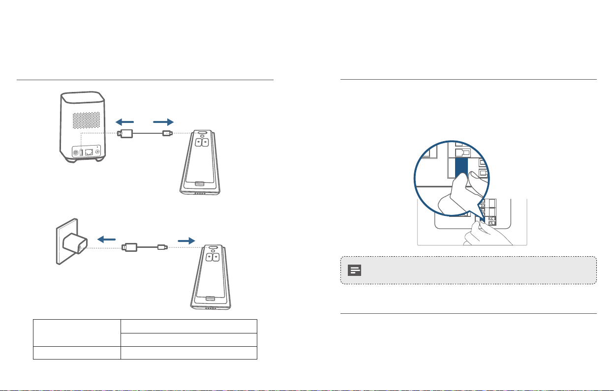
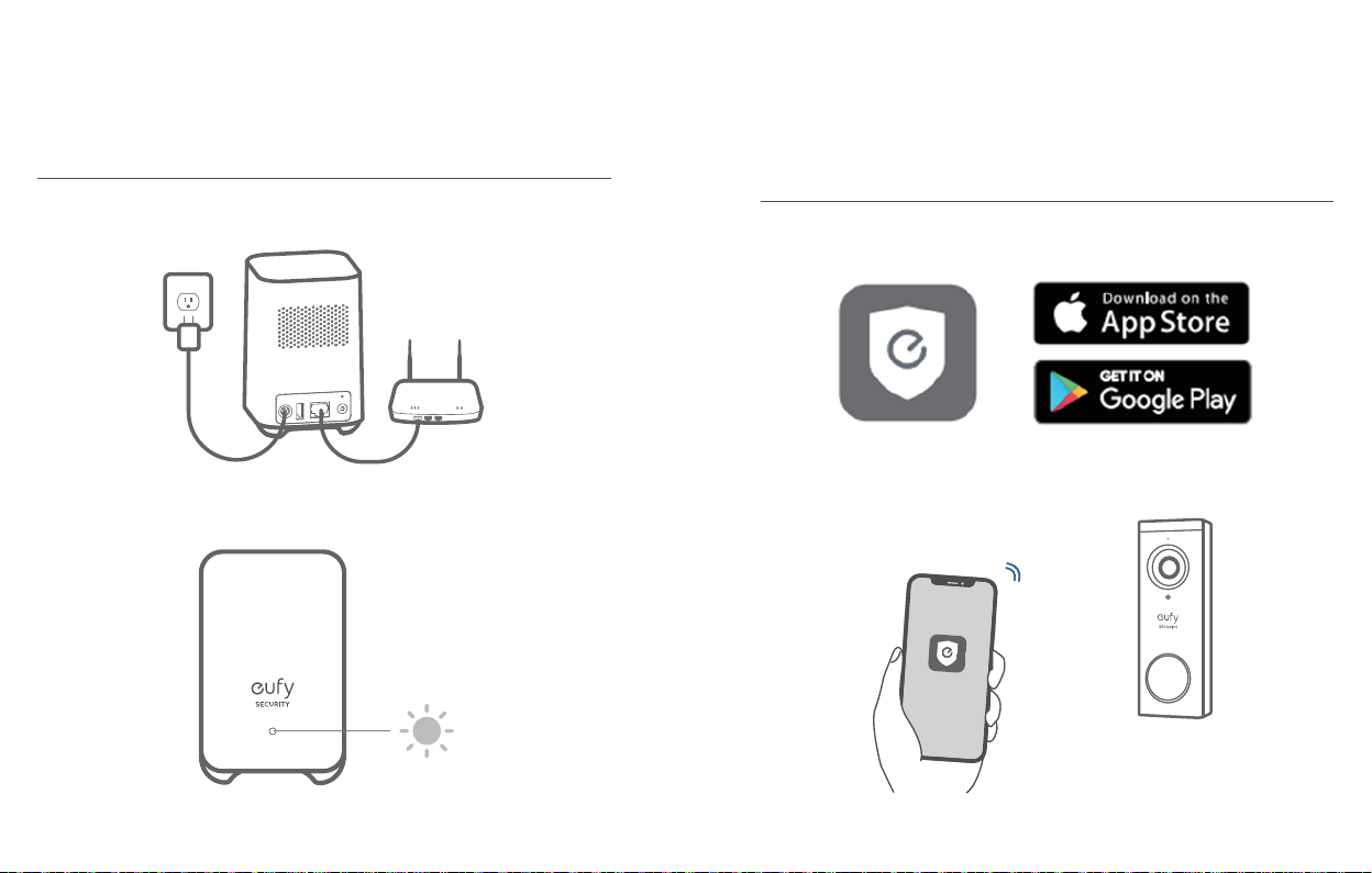
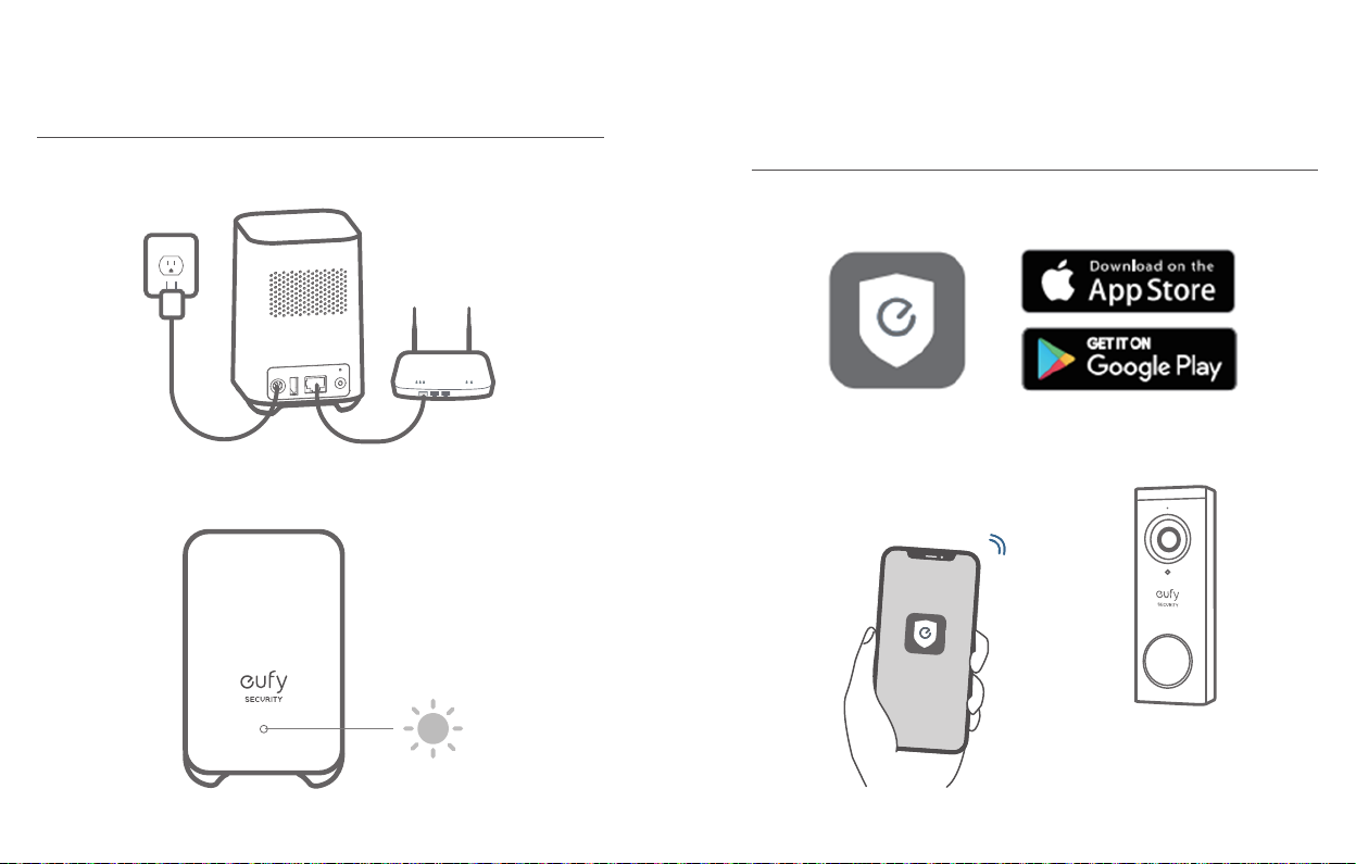
Connect the HomeBase 2 to the Internet
1. Power on the HomeBase 2, then use the ethernet cable provided to connect the
HomeBase 2 to your home router.
2. The LED indicator turns blue (this may take up to 1min) when HomeBase 2 is
ready for setup.
Video Doorbell
English English
06
07
Page 6
STEP 2 SETTING UP THE SYSTEM
STEP 3 DETERMINING THE POWER
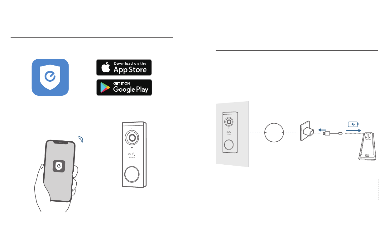
Download the App and Set up the System
Download the Eufy Security app from the App Store (iOS devices) or Google Play
(Android devices).
Sign up for a Eufy Security account, then follow the onscreen instructions to
complete the setup.
OPTION
Option 1 - Battery Powered
1. If you don’t have existing doorbell wiring at the front door, use the built-in
battery. You are free to determine the doorbell position and the mounting is easy
and quick.
2. When the doorbell battery level is low, you need to detach and charge it.
3. If you choose this option, please jump to
.
SPOT
6 months
The battery life varies depending on usage. In most common cases, a
Note:
doorbell may have up to 10 events per day and each recording lasts 20 seconds on
average. Under this scenario, the doorbell battery life can last up to 6 months.
STEP 4 FINDING A MOUNTING
English English
08
09
Page 7
Option 2 - Doorbell Wire Powered
15°
1. If you have existing and working doorbell wiring at the front door, the doorbell
will be powered by the wires constantly. So you don’t need to detach and charge
it after installation.
2. Since the doorbell is connected to the wires, the mounting position is limited.
3. If you choose this option, please jump to
with Doorbell Wires
.
Appendix 3 Powering the Doorbell
8 - 24V AC Doorbell Wiring
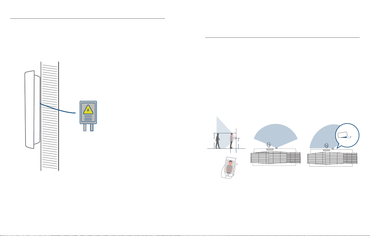
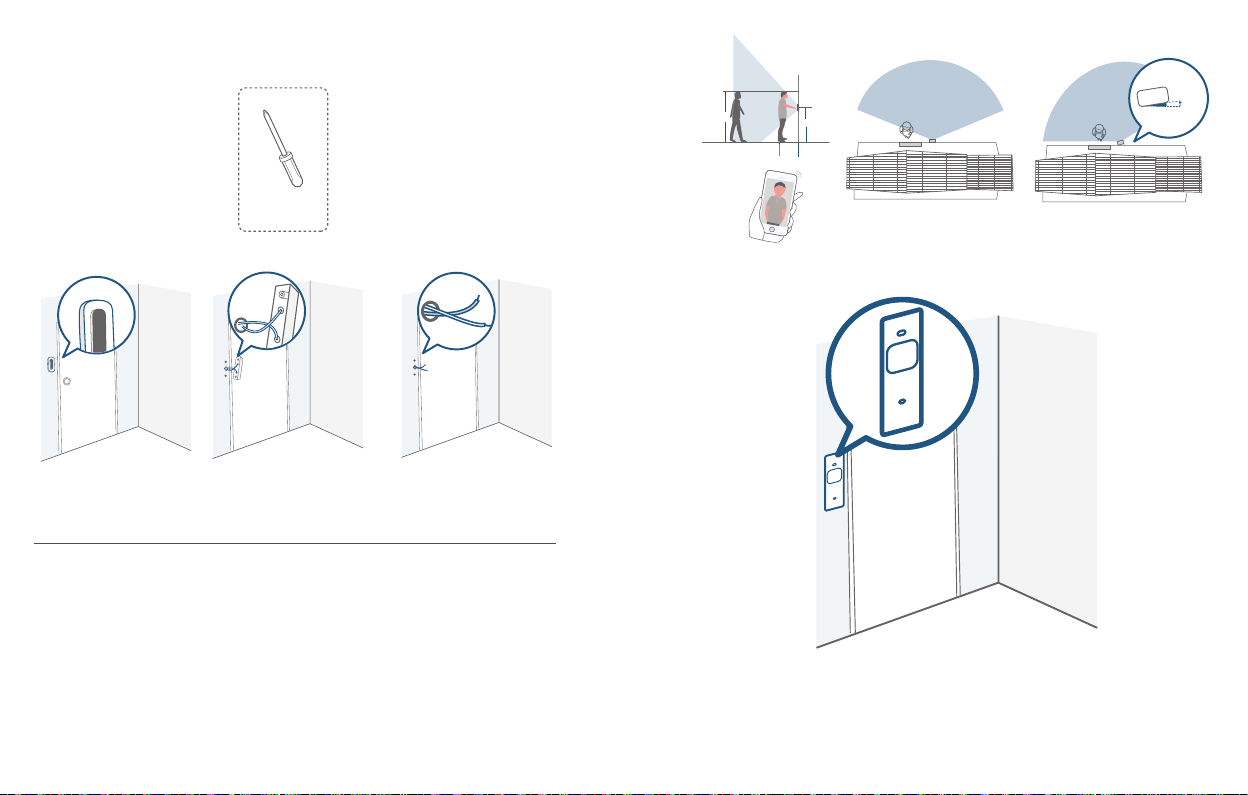
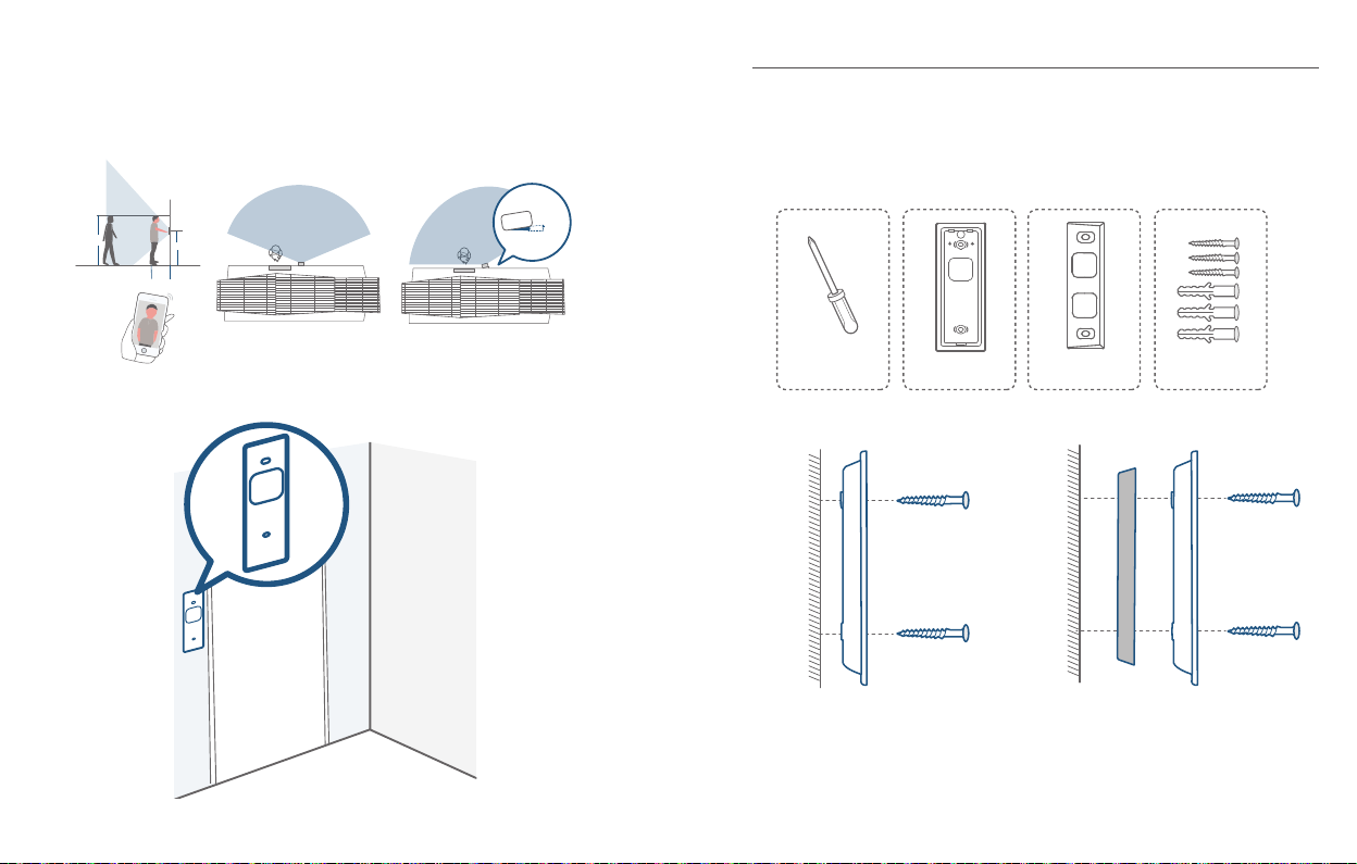
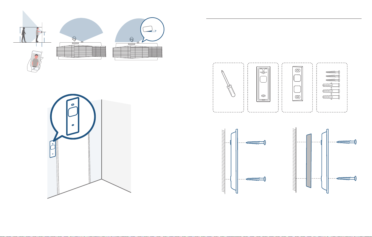
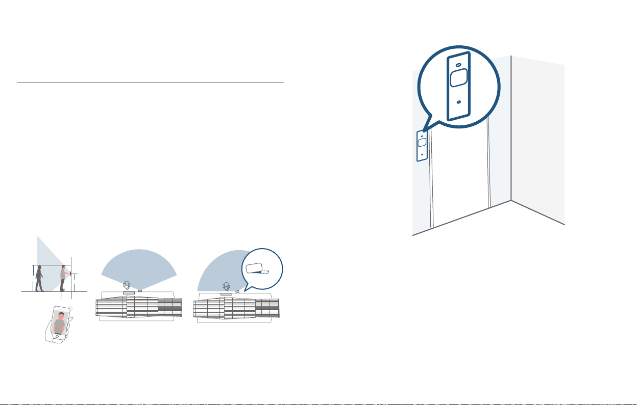
STEP 4 FINDING A MOUNTING SPOT
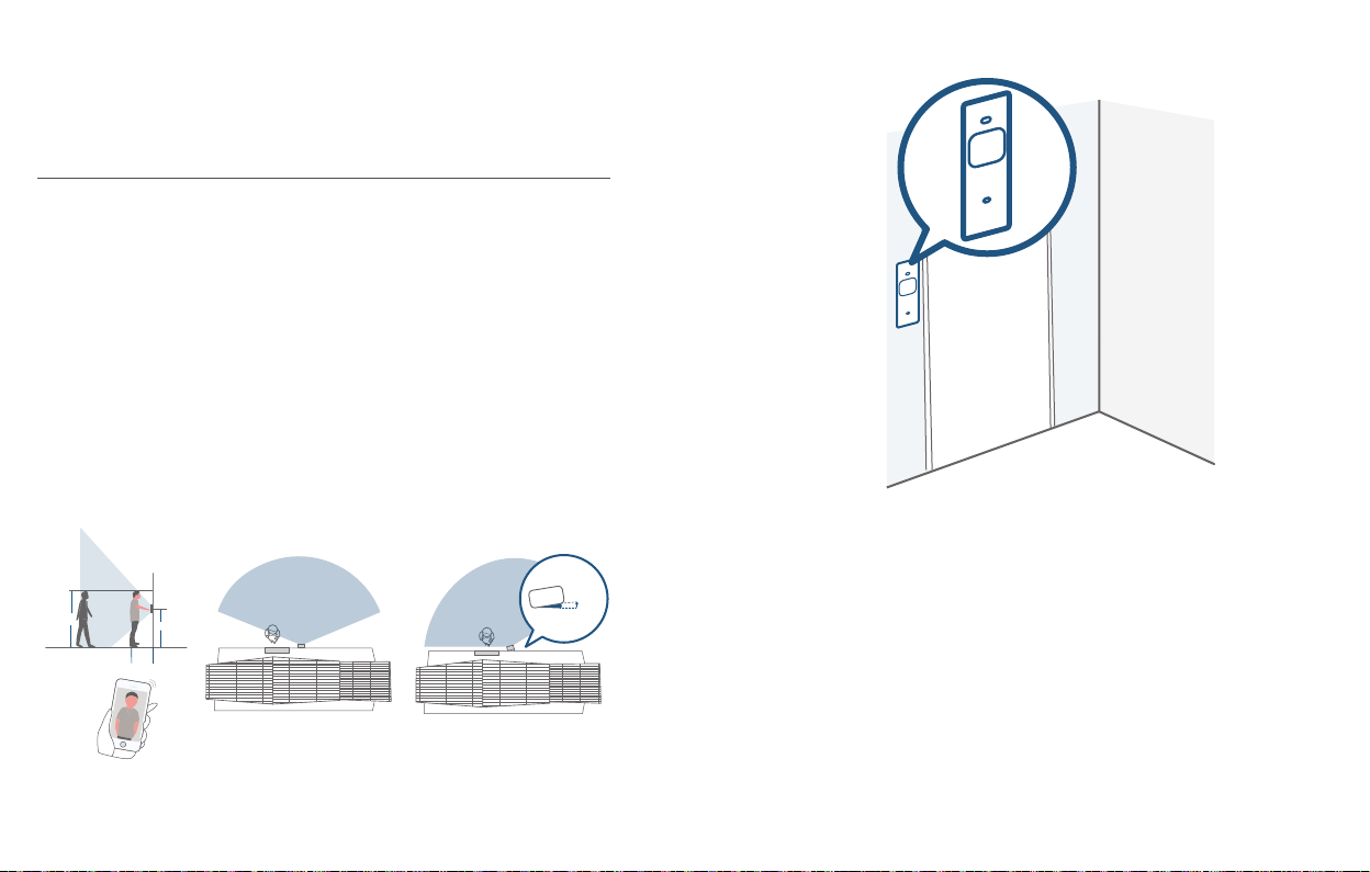
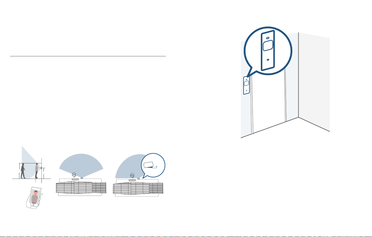
Find a Mounting Spot
Take the video doorbell to your front door and check the live view on the App at
the same time. Find a location where you can get the desired eld of view.
Consider the below factors:
1. Check if you can reuse the existing holes and anchors on the wall or door frame.
2. If you want to place the doorbell close to a side wall, make sure the wall doesn’t
show up in the eld of view. Otherwise IR light will be reected and night vision
will become blurry.
3. If you are drilling the mounting holes for the rst time, the recommended
mounting height is 48" / 1.2 m from the ground.
4. Use the 15° mounting wedge as a supplementary mounting bracket if you wish to
see more on a specic side.
1.76m(5’9”)
1m
(40")
English English
10
1.2m (48")
0.3m
(12")
Door
Video Doorbell
Without 15° Mounting wedge With 15° Mounting wedge
Door
Video Doorbell
11
Page 8
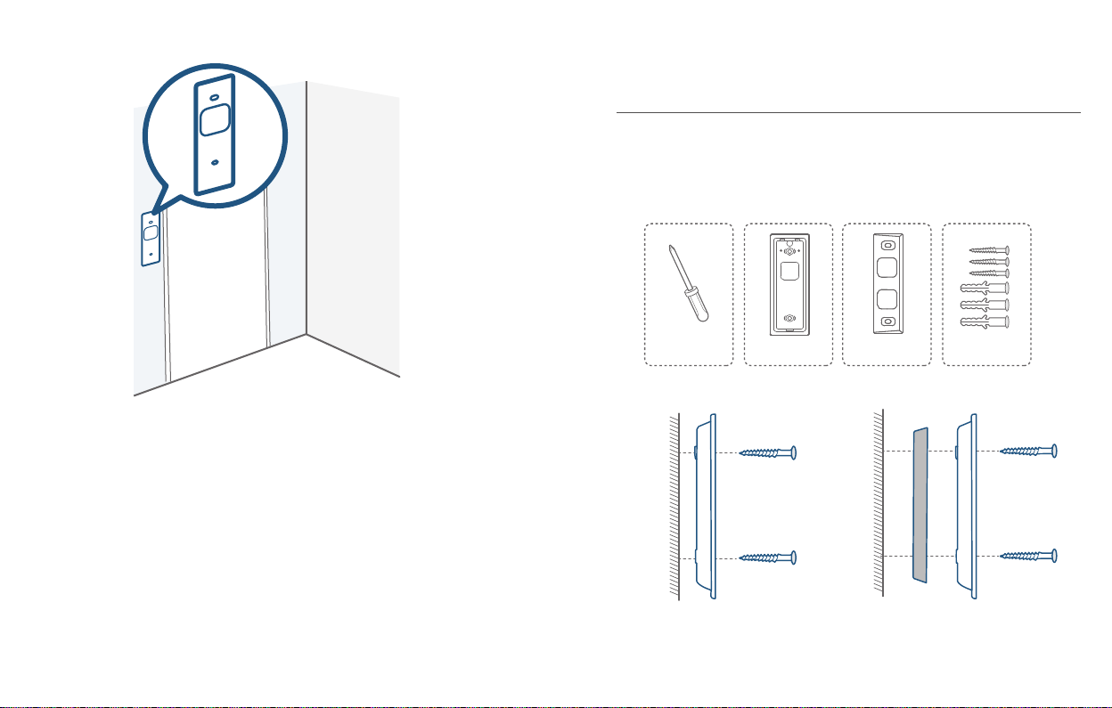
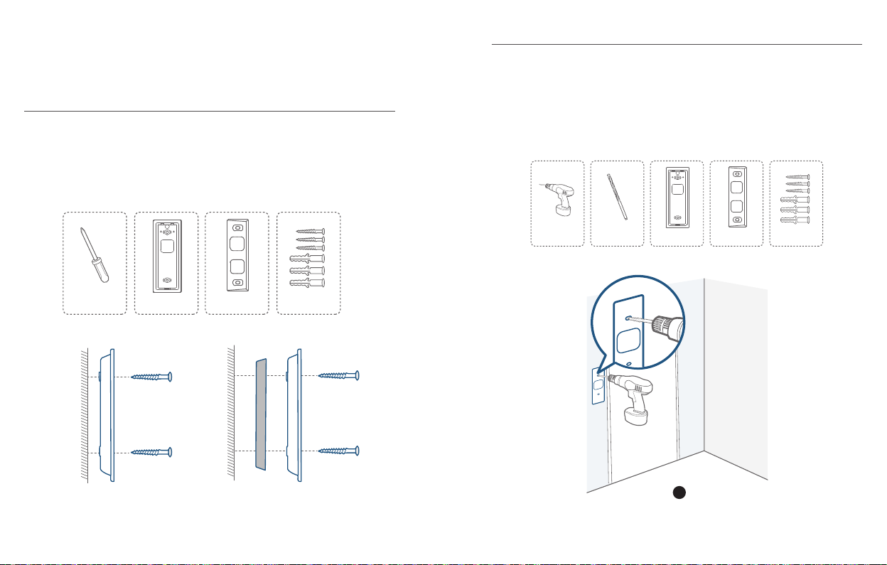
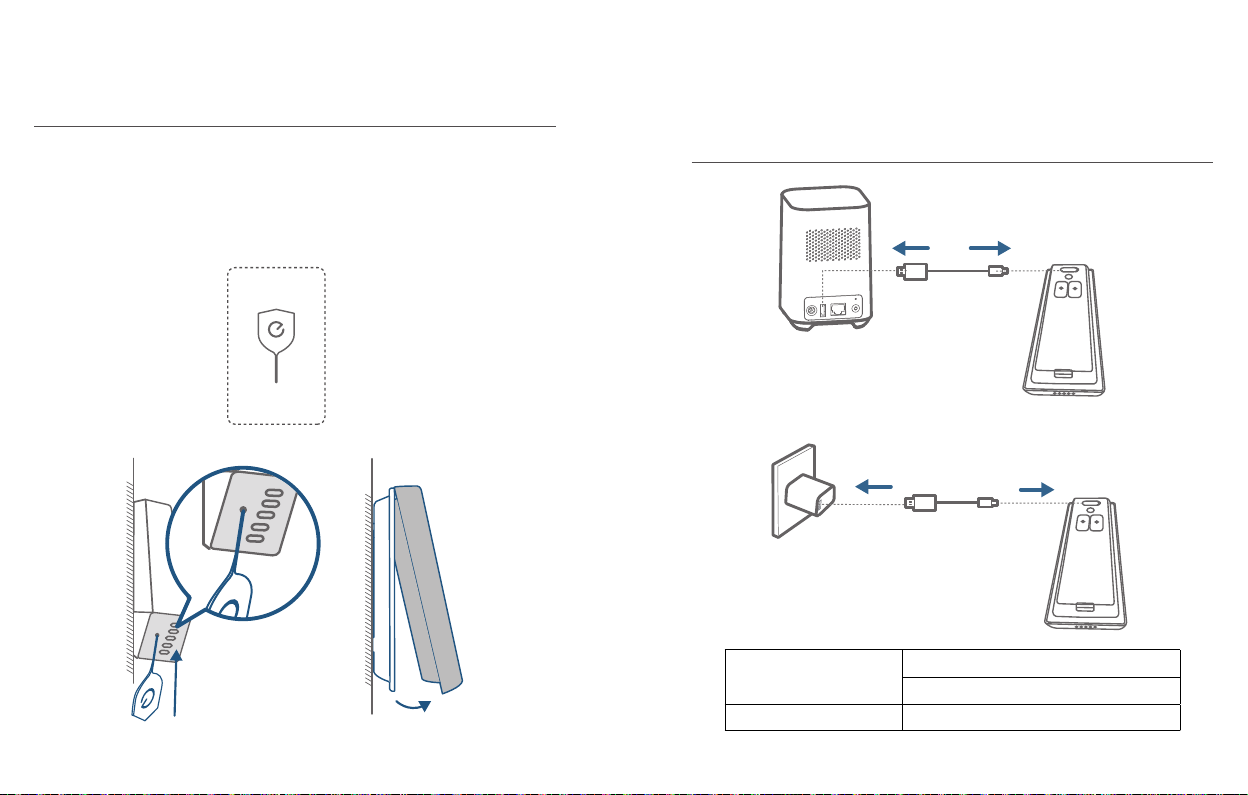
Place the Screw Hole Positioning Card against the wall to mark the position.
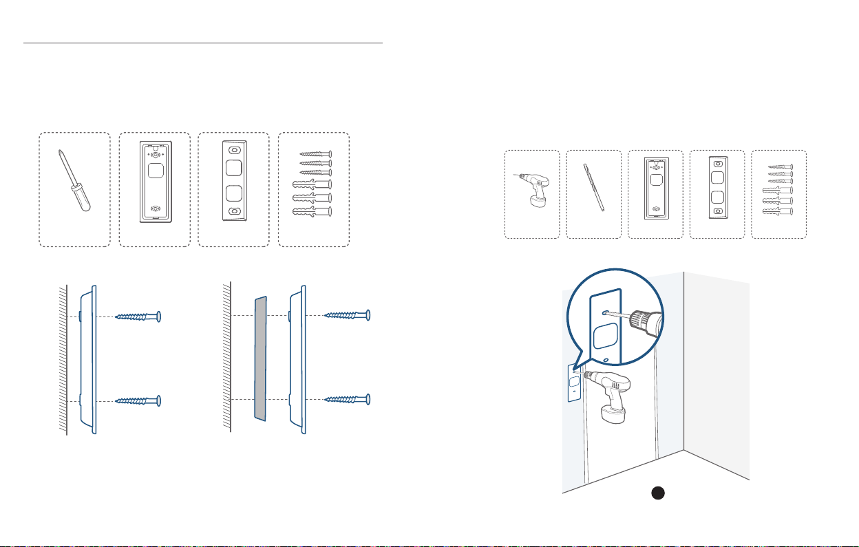
STEP 5 MOUNTING THE BRACKET
Mount the Doorbell on a Wooden Surface
If you’re mounting the doorbell on a wooden surface, you don’t need to pre-drill
pilot holes. Use the provided screws to secure the Mounting Bracket on the wall,
The Screw Hole Positioning Card indicates the position of the screw holes.
What is required: Screwdriver, Mounting Bracket, 15° Mounting Wedge (Optional),
Screw Packs
Phillips-Head Screwdriver
(not provided)
Wall
Mounting
Bracket
Mounting Bracket
(Attached to 15° Mounting
Wedge)
15° Mounting
Wedge (Optional)
Wall
Mounting
Wedge
Screw Packs (Spare screws
and anchors are included.)
Mounting
Bracket
Without 15° Mounting Wedge With 15° Mounting Wedge
English English
12
13
Page 9
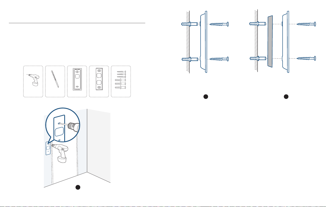
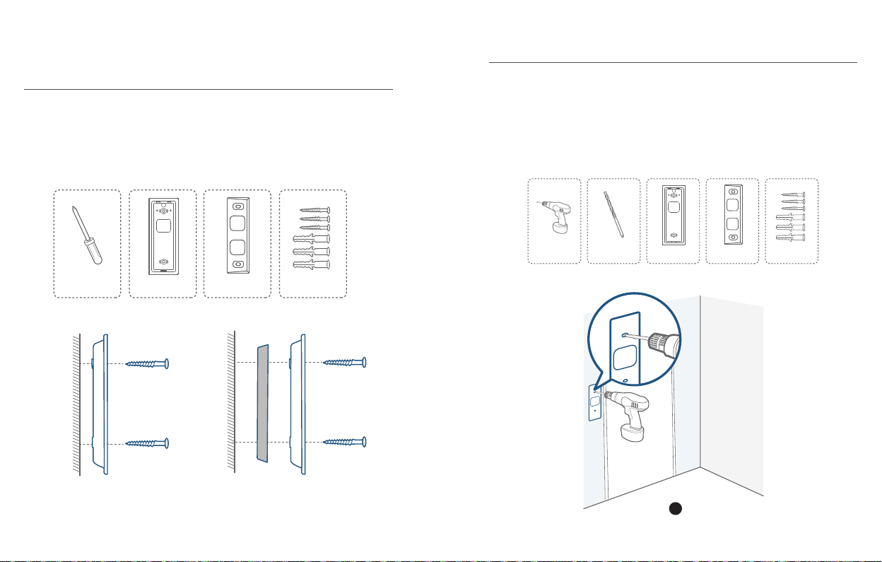
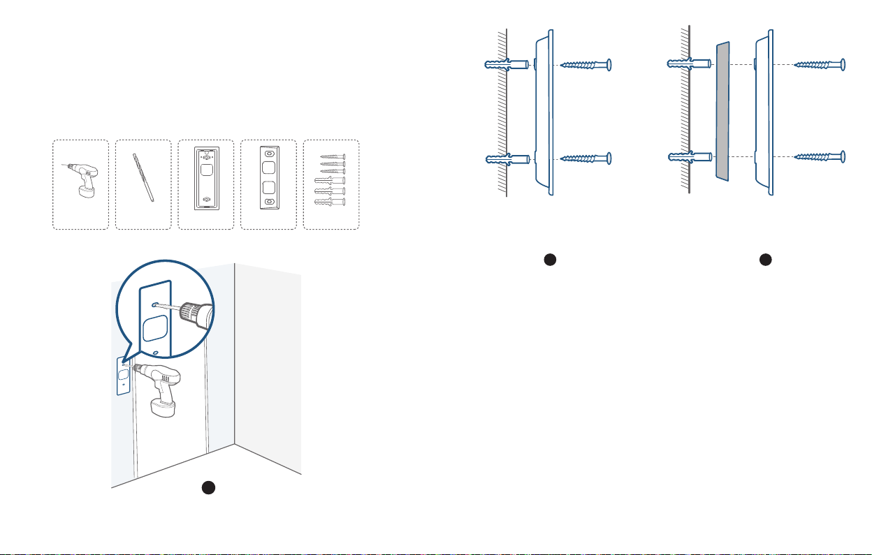
Mount the Doorbell on Surfaces Made Out of Hard
Materials
1. If you’re mounting the doorbell on a surface made out of hard materials, like
brick, concrete, stucco, drill 2 holes through the Screw Hole Positioning Card
with a 15/64”(6mm) drill bit.
2. Insert the provided anchors, and then use the provided long screws to secure the
Mounting Bracket on the wall.
What is required: Power Drill, 15/64”(6 mm) Drill Bit, Mounting Bracket, 15°
Mounting Wedge (Optional), Screw Packs
Wall
Mounting
Wall
Mounting
Bracket
Wedge
Mounting
Bracket
Power Drill
(not provided)
15/64”(6 mm) Drill Bit
Mounting Bracket
(Attached to 15° Mounting
Wedge)
15° Mounting
Wedge (Optional)
Screw Packs (Spare screws
and anchors are included.)
2 2
1
English English
14
Without 15° Mounting Wedge With 15° Mounting Wedge
15
Page 10
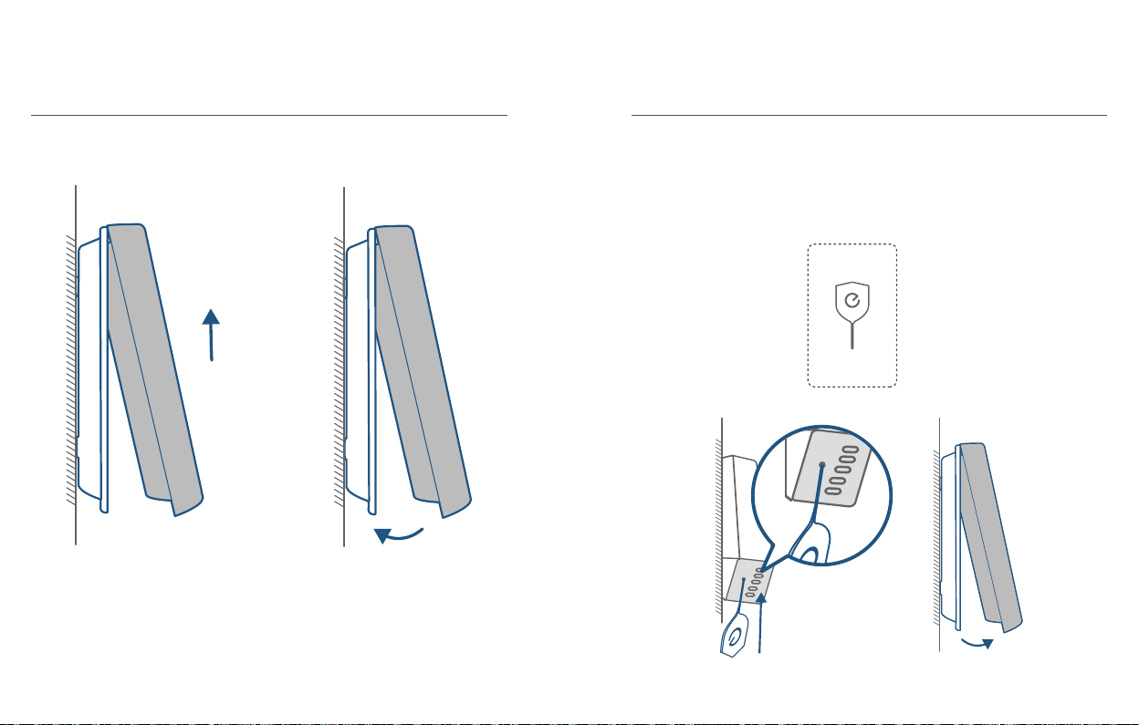
STEP 6 MOUNTING THE DOORBELL
APPENDIX 1 DETACHING THE DOORBELL
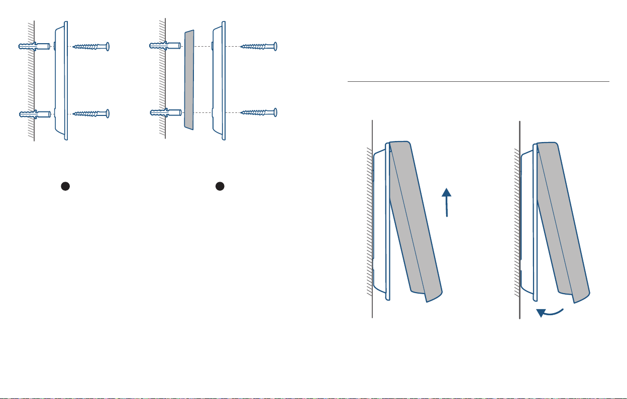
Mount the Doorbell
Align the doorbell on top and then snap it on the bottom. Press it down until it clicks
into place.
You’re all set!
If you want to detach the doorbell or recharge it, please refer to the following
sections.
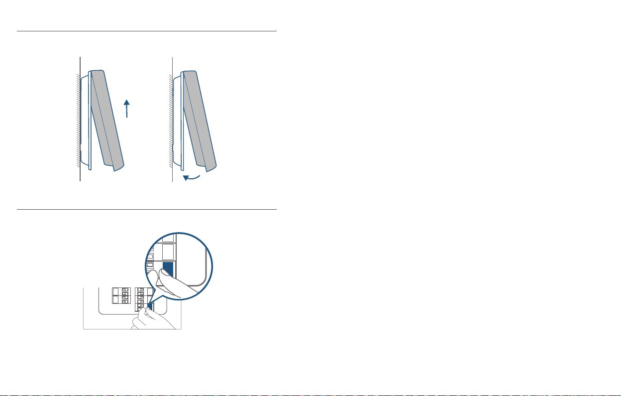
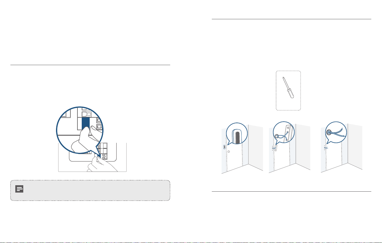
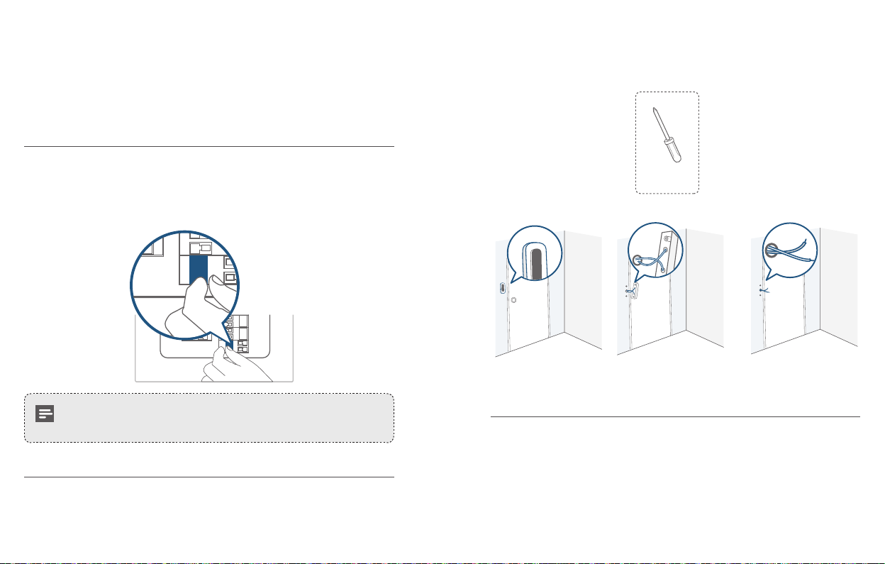
Detach the Doorbell
1. Use the doorbell detaching pin provided if you wish to detach the doorbell from
the Mounting Bracket.
2. Press and hold the hole on the bottom of the doorbell and then lift its bottom to
take it off.
What is required: Doorbell Detaching Pin
Doorbell
Detaching Pin
English English
16
17
Page 11
APPENDIX 2 RECHARGING THE
OFF
APPENDIX 3 POWERING THE DOORBELL
DOORBELL
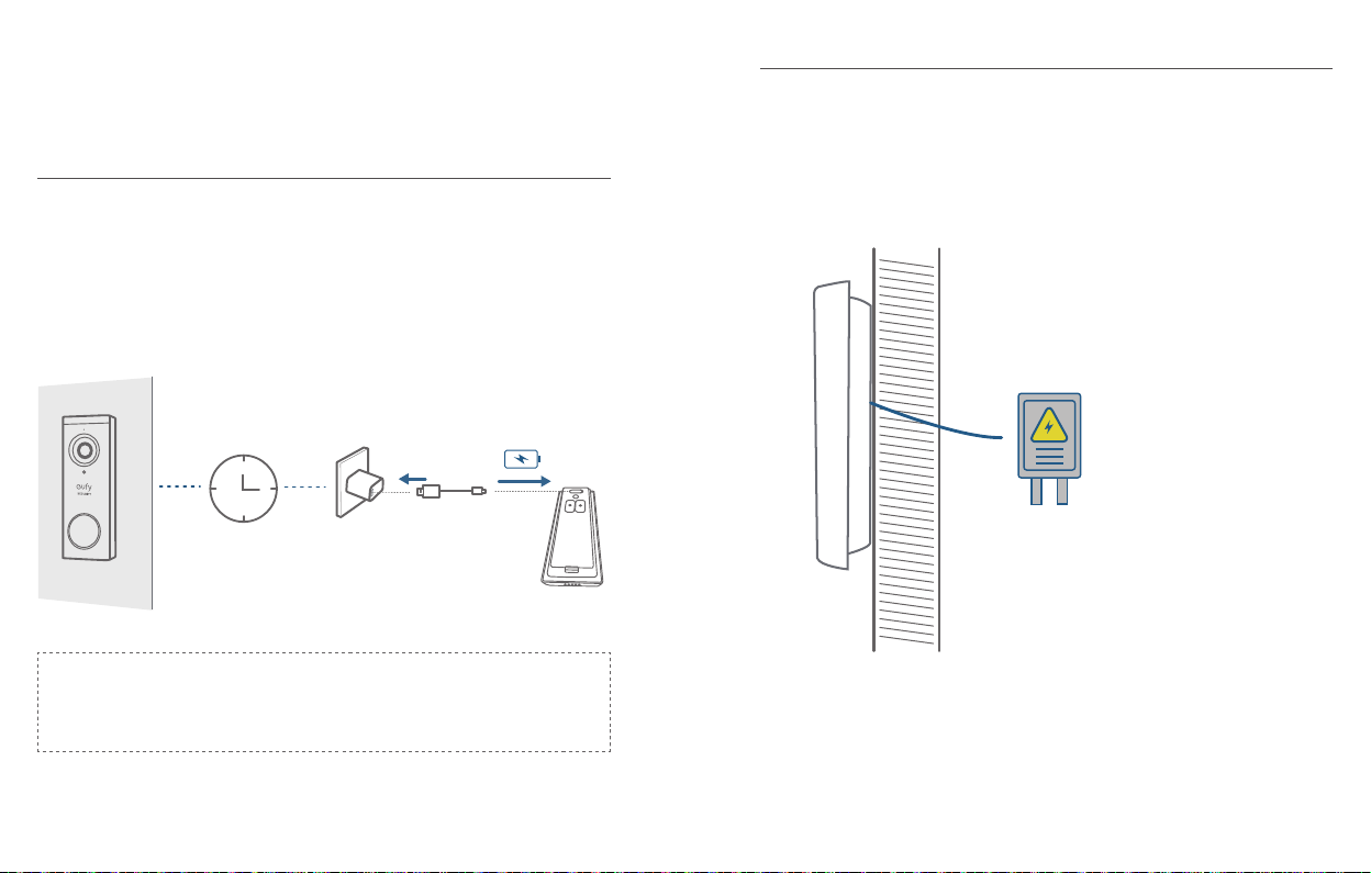
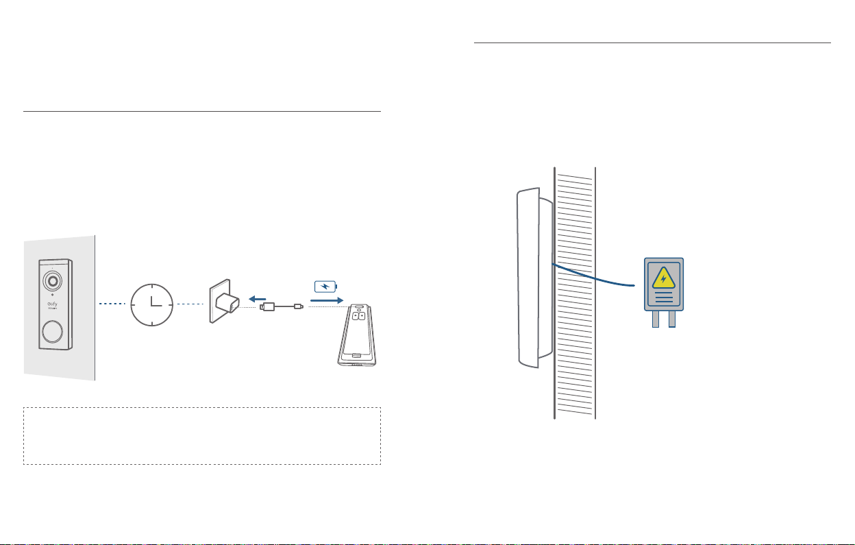
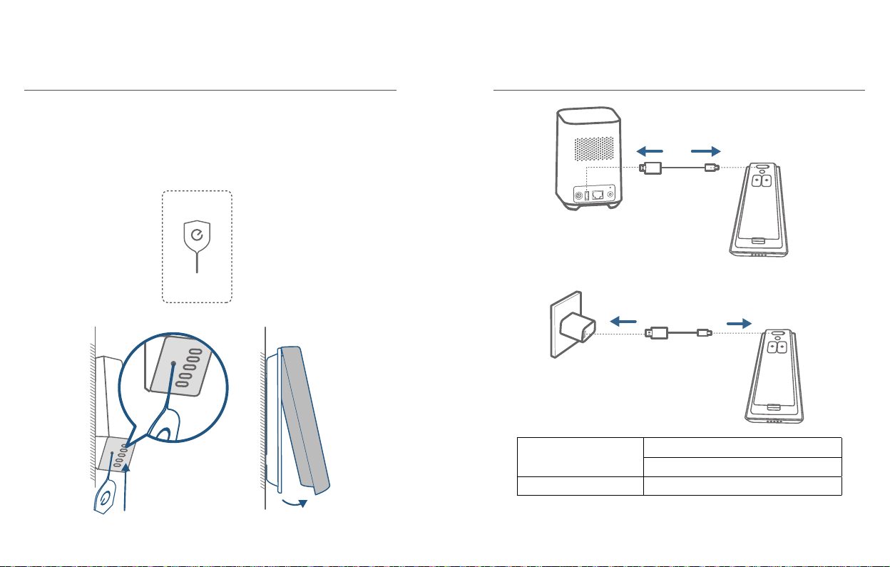
Recharge the Doorbell
LED indication
Charging time 6 hours from 0% to 100%
Charging: Solid orange
Fully charged: Solid cyan
WITH EXISTING DOORBELL WIRES
3.1 Verify whether the doorbell wires are working
1. Ring the existing doorbell to check if it is working. If the doorbell doesn’t ring,
your doorbell wires may be defective. Power the doorbell on its own battery or
consult an electrician to x the wires.
2. Shut off power at the breaker. Turn the lights on / off in your home to make sure
the electricity in your house is properly shut off.
OFF
Always be careful when handling wires. If you’re not comfortable
installing it yourself, have a qualied electrician do it.
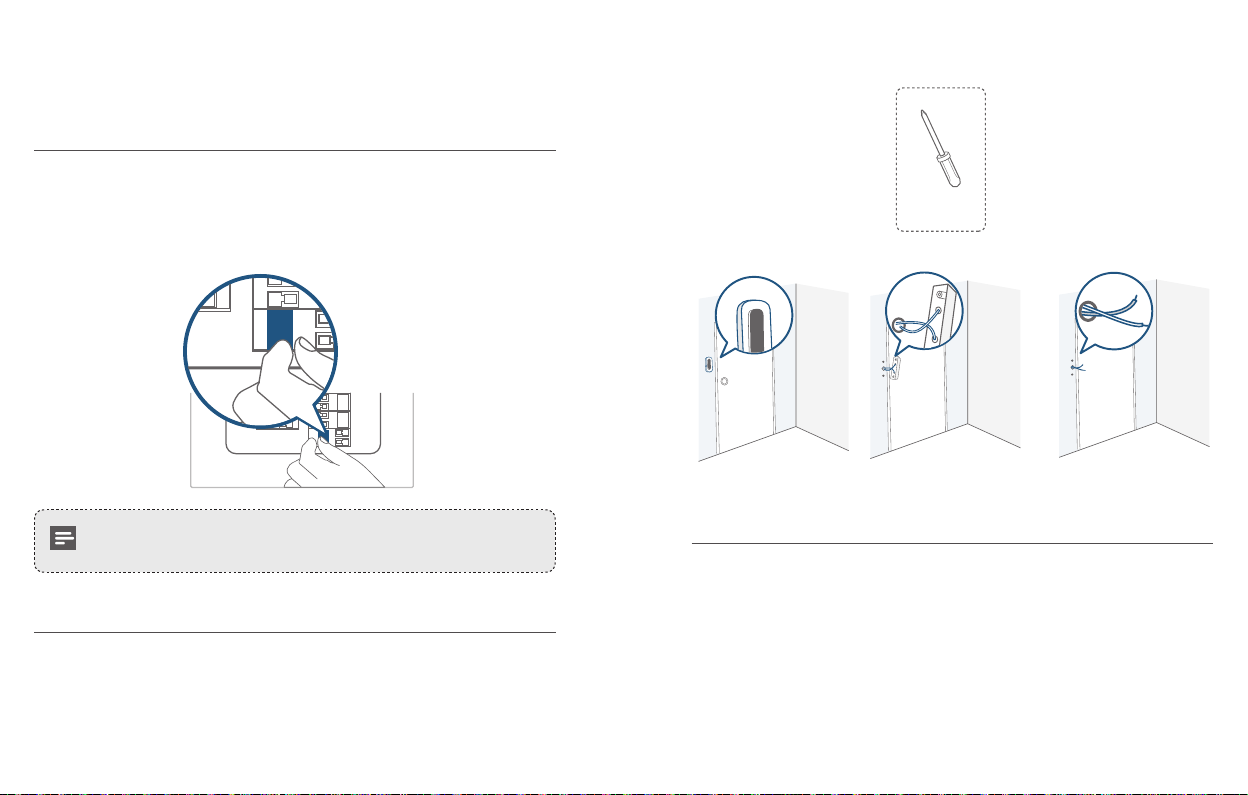
3.2 Detach the Existing Doorbell Button
If you already have existing doorbell wiring:
1. Remove the existing doorbell button with a Phillips-Head screwdriver (not provided).
2. Pull the two wires out carefully when removing the existing doorbell. Straighten
the wire ends if necessary.
English English
18
19
Page 12
What is required: Philips-Head Screwdriver
15°
Phillips-Head Screwdriver
(User provides it.)
3.3 Find a Mounting Spot
1. Determine the mounting position of the doorbell. Consider the below factors:
Check if you can reuse the existing holes and anchors on the wall or door
①
frame.
If you are drilling the mounting holes for the rst time, the recommended
②
mounting height is 48" / 1.2 m from the ground.
Use the 15° mounting wedge as a supplementary mounting bracket if you wish
③
to see more on a specic side.
1.76m(5’9”)
1m
(40")
1.2m (48")
0.3m
(12")
Door
Video Doorbell
Without 15° Mounting wedge With 15° Mounting wedge
Door
Video Doorbell
2. Place the Screw Hole Positioning Card against the wall to mark the position.
English English
20
21
Page 13
3.4 Mount the Bracket
If you’re mounting the doorbell on a wooden surface, you don’t need to pre-drill
pilot holes. Use the provided screws to secure the Mounting Bracket on the wall.
The Screw Hole Positioning Card indicates the position of the screw holes.
What is required: Power Drill, Mounting Bracket, 15° Mounting Wedge (Optional),
Screw Packs
If you’re mounting the doorbell on a surface made out of hard materials, like brick,
concrete, stucco:
Drill 2 holes through the Screw Hole Positioning Card with 15/64”(6mm) drill
①
bit.
Insert the provided anchors, and then use the provided long screws to secure
②
the Mounting Bracket on the wall.
What is required: Power Drill, 15/64”(6mm) Drill Bit, Mounting Bracket, 15°
Mounting Wedge (Optional), Screw Packs
Phillips-Head Screwdriver
(User provides it.)
Wall
Mounting
Bracket
Mounting Bracket
(Attached to 15° Mounting
Wedge)
15° Mounting
Wedge (Optional)
Wall
Mounting
Wedge
Screw Packs (Spare screws
and anchors are included.)
Mounting
Bracket
Power Drill
(not provided)
15/64”(6 mm) Drill Bit
Mounting Bracket
(Attached to 15° Mounting
Wedge)
15° Mounting
Wedge (Optional)
Without 15° Mounting Wedge With 15° Mounting Wedge
1
English English
22
Screw Packs (Spare screws
and anchors are included.)
23
Page 14
Wall
Mounting
Wall
Mounting
Bracket
Without 15° Mounting Wedge With 15° Mounting Wedge
Wedge
Mounting
Bracket
2 2
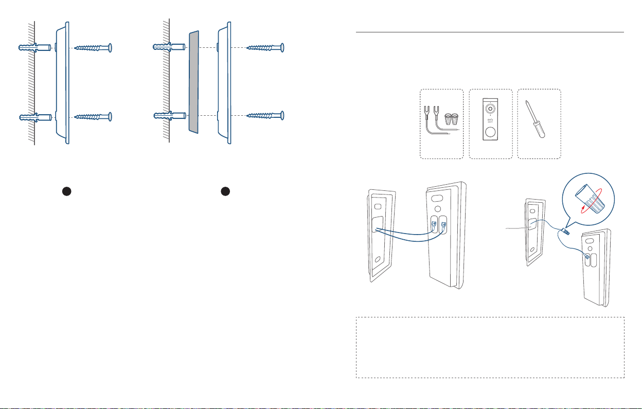
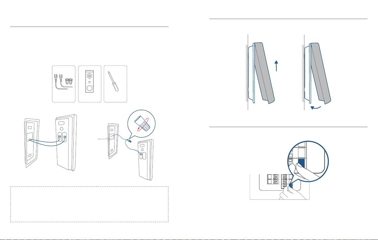
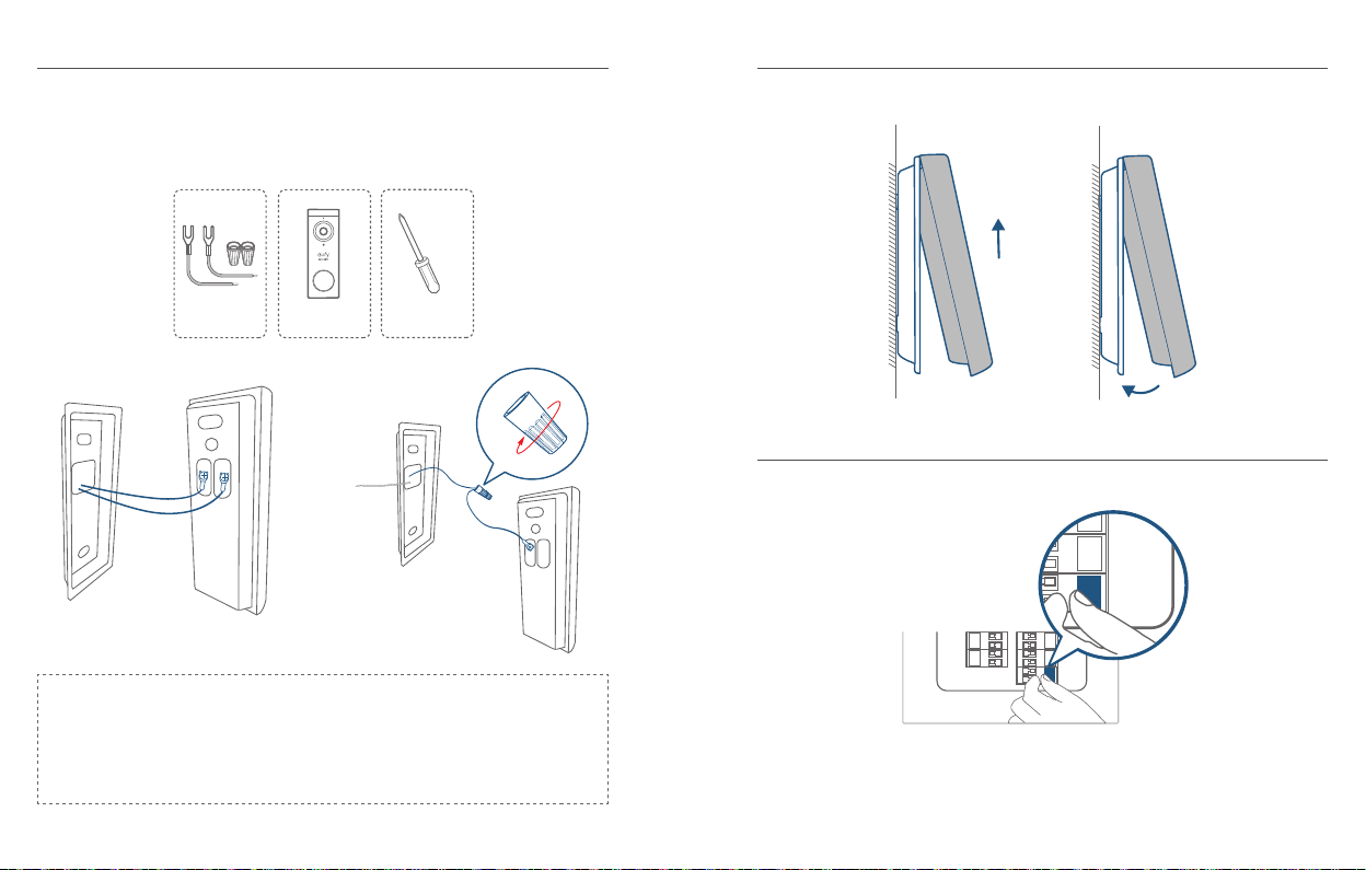
3.5 Connect the Doorbell Wires to the Doorbell
Connect the wires to the terminals at the back of the doorbell, then tighten the
terminal screws. Wire can connect to any terminal.
What is required: Wires and Wire Nuts (Optional), Video Doorbell, Philips-head
Screwdriver
Extension Wires and
Wire Nuts (Optional)
Video Doorbell 2K (Wired)
Model: T8210
Phillips-Head Screwdriver
(User provides it.)
Note:
•
To prevent short-circuit, make sure the wires are not touching each other after
connecting them to the terminals.
•
If the wires are too short, use the extension wires and wire nuts provided to
make them longer. Use electrical wiring tape instead if there is no more space on
the wall for wire nuts.
English English
24
25
Page 15
3.6 Mount the Doorbell on the Bracket
ON
Align the doorbell on top and then snap it on the bottom.
3.7 Restore Power
Switch the master circuit breaker back to ON.
ON
You’re all set!
If you want to detach the doorbell or recharge it, please refer to the corresponding
sections.
NOTICE
FCC Statement
This device complies with Part 15 of the FCC Rules. Operation is subject to the
following two conditions: (1) this device may not cause harmful interference, and (2)
this device must accept any interference received, including interference that may
cause undesired operation.
Warning:
for compliance could void the user's authority to operate the equipment.
Note:
B digital device, pursuant to Part 15 of the FCC Rules. These limits are designed to
provide reasonable protection against harmful interference in a residential installation.
This equipment generates uses and can radiate radio frequency energy and, if not
installed and used in accordance with the instructions, may cause harmful interference
to radio communications. However, there is no guarantee that interference will not
occur in a particular installation. If this equipment does cause harmful interference to
radio or television reception, which can be determined by turning the equipment off
and on, the user is encouraged to try to correct the interference by one or more of
the following measures: (1) Reorient or relocate the receiving antenna. (2) Increase
the separation between the equipment and receiver. (3) Connect the equipment
into an outlet on a circuit different from that to which the receiver is connected. (4)
Consult the dealer or an experienced radio/ TV technician for help.
FCC Radio Frequency Exposure Statement
The device has been evaluated to meet general RF exposure requirements. The device
can be used in xed/mobile exposure condition. The min separation distance is 20cm.
Notice:
All connections to other computing devices must be made using shielded cables to
maintain compliance with FCC regulations.
The following importer is the responsible party:
Company Name: POWER MOBILE LIFE, LLC
Address: 400 108th Ave NE Ste 400, Bellevue, WA 98004-5541
Telephone:1-206-383-8247
Changes or modications not expressly approved by the party responsible
This equipment has been tested and found to comply with the limits for a Class
Shielded cables
English English
26
27
Page 16
This product complies with the radio interference requirements of the European
Community.
Declaration of Conformity
Hereby, Anker Innovations Limited declares that this device is in compliance with the
essential requirements and other relevant provisions of Directive 2014/53/EU. For
the declaration of conformity, visit the Web site: https://www.eufylife.com/.
This product can be used across EU member states.
Do not use the Device in the environment at too high or too low temperature, never
expose the Device under strong sunshine or too wet environment.
The suitable temperature for HomeBase 2 and accessories is -10°C-45°C.
The suitable temperature for Video Doorbell 2K (Wired) and accessories is -20°C -
50°C.
When charging, please place the device in an environment that has a normal room
temperature and good ventilation.
It is recommended to charge the device in an environment with a temperature that
ranges from 5°C~25°C.
RF exposure information: The Maximum Permissible Exposure (MPE) level has been
calculated based on a distance of d=20 cm between the device and the human body. To
maintain compliance with RF exposure requirement, use product that maintain a 20cm
distance between the device and human body.
CAUTION RISK OF EXPLOSION IF BATTERY IS REPLACED BY AN INCORRECT
TYPE. DISPOSE OF USED BATTERIES ACCORDING TO THE INSTRUCTIONS
For HomeBase 2: Wi-Fi Operating Frequency Range: 2412~2472MHz; Wi Max Output
Power: 17.13dBm(EIRP)
SUB-1G Frequency range: 866~866.8MHz; SUB-1G Output Power: 5.492dBm(EIRP)
For Video Doorbell 2K (Wired) :
Wi-Fi Operating Frequency Range: 2412~2472MHz; Wi-Fi Max Output Power: 18.30 dBm
SUB-1G Frequency range: 433.92 MHz; SUB-1G Output Power: 7.407 dBm
Bluetooth Operating Frequency Range: 2402~2480MHz; Bluetooth Max Output Power:
0.77 dBm
The following importer is the responsible party (contact for EU matters only)
Importer: Anker Technology (UK) Ltd
Importer Address: Suite B, Fairgate House, 205 Kings Road, Tyseley, Birmingham,
B11 2AA, United Kingdom
This product is designed and manufactured with high quality materials and
components, which can be recycled and reused.
This symbol means the product must not be discarded as household waste,
and should be delivered to an appropriate collection facility for recycling.
Proper disposal and recycling helps protect natural resources, human health
and the environment. For more information on disposal and recycling of this
product, contact your local municipality, disposal service, or the shop where
you bought this product.
IC Statement
This device complies with Industry Canada licence-exempt RSS standard(s).
Operation is subject to the following two conditions:
(1) this device may not cause interference, and
(2) this device must accept any interference, including interference that may cause
undesired operation of the device."
Le présent appareil est conforme aux CNR d'Industrie Canada applicables aux
appareils radio exempts de licence. L'exploitation est autorisée aux deux conditions
suivantes:
(1) l'appareil nedoit pas produire de brouillage, et
(2) l'utilisateur de l'appareil doit accepter tout brouillage radioélectrique subi, même
si le brouillage est susceptible d'en compromettre le fonctionnement."
This Class B digital apparatus complies with Canadian ICES-003.
Cet appareil numérique de la classe B est conforme à la norme NMB-003 du Canada.
IC RF Statement:
When using the product, maintain a distance of 20cm from the body to ensure
compliance with RF exposure requirements.
Lors de l'utilisation du produit, maintenez une distance de 20 cm du corps an de
vous conformer aux exigences en matière d'exposition RF.
English English
28
29
Page 17

IM LIEFERUMFANG
QSG
INHALTS-
VERZEICHNIS
Im Lieferumfang
Produktübersicht
Funktionsweise Des Systems
Anschliessen Der Homebase
Einrichtung Des Systems
Bestimmen Der Stromoption
31 40
33 42
35 45
36 46
37 47
38 48
Einen Befestigungsort Finden
Anbringen Der Halterung
Anbringen Der Türklingel
Abnehmen Der Türklingel
Auaden Der Türklingel
Betreiben Der Türklingel Mit Einer
Bestehenden Klingelverkabelung
Zur Installation der Video-Türklingelanlage
Video-Türklingel 2K
(batteriebetrieben)
Modell: T8210
FCC ID: 2AOKB-T8210
IC: 23451-T8210
Steckbrücke für
ursprünglichen
Türgong (optional)
Schrauben (mit
Ersatzschrauben und
Dübel)
Montagehalterung
Verlängerungskabel
und Kabelverbinder
(optional)
Kurzanleitung
Bohrschablone
USB-Ladekabel
15°-Montagewinkel
(optional)
Türklingel-Lösestift
Deutsch Deutsch
30
31
Page 18
Für die HomeBase 2-Installation
Modell: HomeBase 2 Netzteil für
HomeBase 2
FCC ID: 2AOKB-T8010
IC: 23451-T8010
Hinweis: Die Ausführung des Netzsteckers hängt von der jeweiligen Region ab.
Ethernetkabel für
HomeBase 2
PRODUKTÜBERSICHT
Video-Türklingel (batteriebetrieben)
Vorderseite:
2
4
6
Rückseite:
Betrieb Anleitung
Eingeschaltet Drücken Sie die SYNC-Taste und lassen Sie sie los
Türklingel zur HomeBase
hinzufügen
Abschalten der Türklingel Drücken Sie die SYNC-Taste innerhalb von 3 Sekunden
Zurücksetzen der Türklingel Die SYNC-Taste drücken und 10 Sekunden lang
1
3
1. Bewegungssensor
2. Mikrofon
3. Kameraobjektiv
4. Umgebungslichtsensor
5. LED-Ring
5
6. Türklingeltaste
7. Lautsprecher
7
1
2
3
1. Mikro-USB-Ladeanschluss
2. Taste SYNC/RESET
3. Kabelklemme für bestehende
Türklingelkabel (optional)
4. Abnahmemechanismus
4
Drücken Sie die SYNC-Taste und lassen Sie sie
gedrückt, bis Sie ein Biep-Geräusch hören
5 Mal hintereinander
gedrückt halten
Deutsch Deutsch
32
33
Page 19
Video-Türklingel (batteriebetrieben)
1
2
3
4 5 6
FUNKTIONSWEISE DES SYSTEMS
FUNKTIONSWEISE DES SYSTEMS
Die Video-Türklingelanlage umfasst zwei Komponenten. Zum einen die an der Tür
anzubringende Türklingel mit Kamera. Zum anderen die HomeBase in Ihrem Zuhause.
Die Video-Türklingel erkennt Bewegungen in Ihrem Außenraum und ermöglicht es
7
Ihnen, Gäste an der Tür jederzeit und überall zu empfangen. Auf dem integrierten
Speicher der HomeBase werden Videos gespeichert. Sobald jemand die Türklingel
betätigt, werden die Personen im Haus darauf aufmerksam gemacht.
1. Status-LED
2. Lautsprecher
3. Stromversorgungs-Anschluss
4. USB-Anschluss
Deutsch Deutsch
34
5. Ethernet-Anschluss
6. SYNC/ALARM AUS-Taste
7. Reset-Taste
Türgong
Video-Türklingel
35
Page 20
SCHRITT 1 – ANSCHLIESSEN DER
SCHRITT 2 – EINRICHTUNG DES
HOMEBASE
HomeBase 2 mit dem Internet verbinden
1. Schalten Sie die HomeBase 2 ein und schließen Sie sie über das im Lieferumfang
enthaltene Ethernet-Kabel an Ihren Heimrouter an.
2. Die LED-Anzeige leuchtet blau, wenn die HomeBase 2 bereit für die Einrichtung
ist (dies kann bis zu 1 Minute dauern).
SYSTEMS
Laden Sie die App herunter und richten Sie das
System ein.
Laden Sie die eufy Security-App aus dem App Store (iOS-Geräte) oder bei Google
Play (Android) herunter.
Melden Sie sich für ein Eufy Security-Konto an und befolgen Sie dann die Anweisungen
auf dem Bildschirm, um die Einrichtung abzuschließen.
Deutsch Deutsch
36
37
Page 21
SCHRITT 3 – BESTIMMEN DER
STROMOPTION
Option 1 – Batteriebetrieben
1. Wenn an Ihrer Haustür keine Leitungen für die Türklingel vorhanden sind,
verwenden Sie die integrierte Batterie. Sie können die Position der Türklingel frei
bestimmen, und die Anbringung erfolgt schnell und einfach.
2. Wenn der Batteriestand der Türklingel niedrig ist, müssen Sie sie abnehmen und
laden.
3. Wenn Sie nach dieser Möglichkeit vorgehen, gehen Si
EINEN BEFESTIGUNGSORT FINDEN
6 Monate
Hinweis: Die Verwendungszeit der Batterie hängt von der Verwendung ab. Unter
normalen Umständen wird die Türklingel bis zu 10 Mal am Tag verwendet, und jede
Aufnahme dauert durchschnittlich 20 Sekunden. Unter diesen Umständen kann die
Batterie bis zu 6 Monate halten.
.
e bitte zu SCHRITT 4 –
Option 2 – Kabelbetriebene Türklingel
1. Wenn Sie an Ihrer Haustür über eine funktionstüchtige Türklingelverkabelung
verfügen, wird die Türklingel über diese Kabel kontinuierlich mit Strom versorgt.
Sie müssen Sie nach der Befestigung nicht abnehmen und laden.
2. Da die Türklingel mit den Kabeln verbunden ist, kann der Befestigungspunkt nicht
beliebig gewählt werden.
3. Wenn Sie nach dieser Option vorgehen möchten, gehen Sie bitte zu
Betreiben der Türklingel mit einer Klingelverkabelung“
8 – 24 V AC
Türklingelverkabelung
„Anhang 3 –
.
Deutsch Deutsch
38
39
Page 22
SCHRITT 4 – EINEN
15°
BEFESTIGUNGSORT FINDEN
Suchen Sie einen Befestigungsort
Bringen Sei die Video-Türklingel zu Ihrer Haustür und überprüfen Sie gleichzeitig
die Echtzeitanzeige auf der App. Suchen Sie einen Ort, an dem Sie das gewünschte
Blickfeld erhalten.
Bedenken Sie die folgenden Faktoren:
1. Überprüfen Sie, ob Sie die bestehenden Löcher und Dübel an der Haustürwand
erneut verwenden können.
2. Wenn Sie die Türklingel nahe einer Seitenwand anbringen möchten, achten Sie
bitte darauf, dass die Wand nicht im Blickfeld der Kamera liegt. Ansonsten wird
die Infrarotstrahlung reektiert, und Nachtaufnahmen werden verschwommen
dargestellt.
3. Wenn Sie die Befestigungslöcher das erste Mal in die Wand bohren, wird eine
Höhe von 1,2 m (48 Zoll) über den Boden empfohlen.
4. Die Verwendung des 15°-Montagewinkels als zusätzliche Montagehalterung
empehlt sich, wenn einen größeren Blickumfang auf einer Seite haben möchten.
Halten Sie die Bohrschablone an die Wand, um die Positionen zu markieren.
1.76m(5’9”)
1m
(40")
Deutsch Deutsch
40
1.2m (48")
0.3m
(12")
Tür
Video-Türklingel
Ohne 15°-Montagewinkel Mit 15°-Montagewinkel
Tür
Video-Türklingel
41
Page 23
SCHRITT 5 – ANBRINGEN DER
HALTERUNG
Anbringen der Türklingel an einer Oberfläche aus Holz
Wenn Sie die Türklingel an einer Oberfläche aus Holz anbringen, muss nicht
vorgebohrt werden. Verwenden Sie die im Lieferumfang enthaltenen Schrauben, um
die Montagehalterung an der Wand anzubringen. Mit der Bohrschablone wird die
Position der Bohrlöcher angegeben.
Hierzu erforderlich: Schraubenzieher, Montagehalterung, 15°-Montagewinkel
(optional), Schrauben
Anbringen der Türklingel an harten Oberflächen
1. Wenn Sie die Türklingel an Oberächen aus hartem Material (z. B. Ziegelsteine,
Beton, Stuck) anbringen, bohren Sie mit einem 15/64-Zoll-Bohreinsatz (6 mm) mit
Hilfe der Bohrschablone zwei Löcher.
2. Stecken Sie die gelieferten Dübel rein und bringen Sie dann die Montagehalterung
mit den Langschrauben an der Wand an.
Hierzu erforderlich: Bohrmaschine, 6-mm- bzw. 15/64-Zoll-Bohreinsatz,
Montagehalterung, 15°-Montagewinkel (optional), Schrauben
Power Drill
(not provided)
Kreuzschlitzschraubendreher
(nicht im Lieferumfang
enthalten)
Mauer
Montagehalterung
Ohne 15°-Montagewinkel Mit 15°-Montagewinkel
Deutsch Deutsch
42
Montagehalterung
(am 15°-Montagewinkel
befestigt)
15°-Montage-
winkel (optional)
Mauer
Montage-
Winkel
Schrauben (Ersatzschrauben)
and anchors are included.)
Montagehalterung
6-mm- bzw. 15/64-Zoll-
Bohreinsatz
Montagehalterung
(am 15°-Montagewinkel
befestigt)
1
15°-Montage-
winkel (optional)
Schrauben (Ersatzschrauben)
and anchors are included.)
43
Page 24
Mauer
Montage-
Mauer
Montagehalterung
Ohne 15°-Montagewinkel Mit 15°-Montagewinkel
2 2
Winkel
Montagehalterung
SCHRITT 6 – ANBRINGEN DER
TÜRKLINGEL
Anbringen der Türklingel
Richten Sie die Türklingel an der Oberseite aus und lassen Sie sie einrasten. Drücken
Sie auf die Klingel, bis sie mit einem Klick-Geräusch einrastet.
Das war's!
Wenn Sie die Türklingel abnehmen oder aufladen möchten, finden Sie in den
folgenden Abschnitten nähere Angaben.
Deutsch Deutsch
44
45
Page 25

ANHANG 1 – ABNEHMEN DER TÜRKLINGEL
Aushängen der Türklingel
ANHANG 2 – AUFLADEN DER
TÜRKLINGEL
1. Verwenden Sie zum Abnehmen der Türklingel von der Montagehalterung den
mitgelieferten Lösestift.
2. Stecken Sie mit einer Hand den Lösestift in das Loch an der Unterseite der
Türklingel ein und heben Sie mit der anderen Hand das obere Ende weg.
Hierzu erforderlich: Türklingel-Lösestift
Türklingel-
Lösestift
Aufladen der Türklingel
LED-Anzeige
Ladedauer In 6 Stunden von 0 % auf 100 %
Auaden: Leuchtet orange
Vollständig aufgeladen: Leuchtet türkis
Deutsch Deutsch
46
47
Page 26
ANHANG 3 – BETREIBEN DER
OFF
TÜRKLINGEL MIT EINER BESTEHENDEN
KLINGELVERKABELUNG
3.1 Sicherstellen, dass die Türklingelverkabelung
betriebsbereit ist
1. Betätigen Sie die vorhandene Türklingel, um zu überprüfen, ob sie funktioniert.
Wenn die Türklingel nicht klingelt, kann die Verkabelung defekt sein. Versorgen
Sie die Türklingel über die integrierte Batterie oder wenden Sie sich an einen
Elektriker, um die Kabel zu reparieren.
2. Schalten Sie die Sicherung aus. Schalten Sie das Licht in Ihrem Haus ein/aus, um
sicherzustellen, dass die Stromversorgung ordnungsgemäß getrennt wurde.
OFF
3.2 Abnehmen der bestehenden Türklingel
Wenn Sie bereits über eine Türklingelverkabelung verfügen:
1. Entfernen Sie die bestehende Türklingel mit einem Kreuzschlitzschraubendreher (nicht
im Lieferumfang enthalten).
2. Ziehen Sie die beiden Drähte vorsichtig heraus, wenn Sie die bestehende
Türklingel entfernen. Begradigen Sie die Drahtenden bei Bedarf.
Hierzu erforderlich: Kreuzschlitzschraubendreher
Kreuzschlitzschraubendreher
(User provides it.)
48
Seien Sie bei der Handhabung von Kabeln immer vorsichtig. Wenn Sie
sich bei der Installation nicht sicher fühlen, lassen Sie sie von einem
qualizierten Elektriker vornehmen.
3.3 Einen Befestigungsort suchen
1. Legen Sie den Anbringort der Türklingel fest. Bedenken Sie die folgenden
Faktoren:
Überprüfen Sie, ob Sie die bestehenden Löcher und Dübel an der
①
Haustürwand erneut verwenden können.
Deutsch Deutsch
49
Page 27
Wenn Sie die Befestigungslöcher das erste Mal in die Wand bohren, wird eine
15°
②
Höhe von 1,2 m (48 Zoll) über den Boden empfohlen.
Die Verwendung des 15°-Montagewinkels als zusätzliche Montagehalterung
③
empfiehlt sich, wenn einen größeren Blickumfang auf einer Seite haben
möchten.
3.4 Anbringen der Halterung
Wenn Sie die Türklingel an einer Oberfläche aus Holz anbringen, muss nicht
vorgebohrt werden. Bringen Sie die Montagehalterung mit den gelieferten Schrauben
an der Wand an. Mit der Bohrschablone wird die Position der Bohrlöcher angegeben.
Hierzu erforderlich: Bohrmaschine, Montagehalterung, 15°-Montagewinkel
(optional), Schrauben
1.76m(5’9”)
1m
(40")
2. Halten Sie die Bohrschablone an die Wand, um die Positionen zu markieren.
1.2m (48")
0.3m
(12")
Tür
Video-Türklingel
Ohne 15°-Montagewinkel Mit 15°-Montagewinkel
Tür
Video-Türklingel
Kreuzschlitzschraubendreher
(User provides it.)
Mauer
Montagehalterung
Montagehalterung
(am 15°-Montagewinkel
befestigt)
15°-Montage-
winkel (optional)
Mauer
Montage-
Winkel
Schrauben (Ersatzschrauben)
and anchors are included.)
Montagehalterung
Ohne 15°-Montagewinkel Mit 15°-Montagewinkel
Deutsch Deutsch
50
51
Page 28

Wenn Sie die Türklingel an einer harten Oberäche (z. B. Ziegelsteine, Beton, Stuck)
anbringen:
Bohren Sie mit einem 6-mm- bzw. 15/64-Zoll-Bohreinsatz mit Hilfe der
①
Bohrschablone 2 Löcher.
Stecken Sie die gelieferten Dübel rein und bringen Sie dann die
②
Montagehalterung mit den Langschrauben an der Wand an.
Hierzu erforderlich: Bohrmaschine, 6-mm- bzw. 15/64-Zoll-Bohreinsatz,
Montagehalterung, 15°-Montagewinkel (optional), Schrauben
Bohrmaschine
(nicht im Lieferumfang
enthalten)
6-mm- bzw. 15/64-Zoll-
Bohreinsatz
Montagehalterung
(am 15°-Montagewinkel
befestigt)
15°-Montage-
winkel (optional)
Schrauben (Ersatzschrauben)
and anchors are included.)
Mauer
Montage-
Mauer
Montagehalterung
Winkel
Montagehalterung
Ohne 15°-Montagewinkel Mit 15°-Montagewinkel
2 2
1
Deutsch Deutsch
52
53
Page 29
3.5 Anschließen der Türklingelverkabelung an die
ON
Türklingel
Verbinden Sie die Leiter mit den Anschlüssen an der Rückseite der Türklingel und
ziehen Sie dann die Anschlussschrauben fest. Es spielt hierbei keine Rolle, welchen
Leiter Sie an welchem Anschluss anbinden.
Hierzu erforderlich: Kabel und Kabelverbinder (optional), Video-Türklingel,
Kreuzschlitzschraubendreher
3.6 Anbringen der Türklingel an der Halterung
Richten Sie die Türklingel an der Oberseite aus und lassen Sie sie einrasten.
Verlängerungskabel und
Kabelverbinder
(optional)
Video-Türklingel 2K
(verdrahtet)
Modell: T8210
Kreuzschlitzschraubendreher
(User provides it.)
3.7 Wiederherstellen der Stromzufuhr
Schalten Sie die Hauptsicherung wieder auf EIN.
Hinweis:
•
Achten Sie darauf, dass sich die beiden Leiter nach dem Anschließen nicht
berühren, um einen möglichen Kurzschluss zu vermeiden.
•
Sollten die Drähte zu kurz sein, verwenden Sie die gelieferten Verlängerungskabel
und Kabelverbinder, um sie zu verlängern. Sollte auf der Wand kein Platz für
Kabelverbinder sein, verwenden Sie stattdessen Isolierband.
Deutsch Deutsch
54
Das war's!
Wenn Sie die Türklingel abnehmen oder aufladen möchten, finden Sie in den
entsprechenden Abschnitten nähere Angaben.
ON
55
Page 30

CONTENIDO
QSG
TABLA
DE CONTENIDOS
Contenido
Descripción Del Product
Funcionamiento Del Sistema
Conexión De Homebase
Conguración Del Sistema
SeleccióN De La Opción De
Alimentación
57 66
59 68
61 71
62 72
63 73
64 74
Identicación De La Ubicación De
Instalación
Instalación Del Soporte
Instalación Del Timbre
Desmontaje Del Timbre
Carga Del Timbre
Alimentación Del Timbre A Través
Del Cableado De Timbre Existente
Para la instalación del timbre con vídeo
Timbre con vídeo 2K
(alimentado por
batería)
Modelo: T8210
Id. de FCC: 2AOKB-T8210
IC: 23451-T8210
Puente para el
dispositivo sonoro
original (opcional)
Paquetes de tornillos
(con tornillos y tacos de
repuesto incluidos)
Soporte de montaje
Cables de extensión
y tuercas para cables
(opcional)
Guía de inicio rápido
Tarjeta de
posicionamiento del
oricio para tornillos
Cable de carga
USB
Cuña de montaje de
15° (opcional)
Clavija de extracción
del timbre
Español Español
56
57
Page 31

Para la instalación de HomeBase2
Modelo:
HomeBase 2
Id. de FCC: 2AOKB-T8010
IC: 23451-T8010
Nota: El enchufe del adaptador de alimentación puede variar en función de la
región.
Adaptador de alimentación
para HomeBase 2
Cable Ethernet para
HomeBase 2
DESCRIPCIÓN DEL PRODUCTO
Timbre con vídeo (alimentado por batería)
Vista frontal:
2
4
6
Vista posterior:
Funcionamiento Instrucciones
Encendido Pulse el botón Sincronizar
Adición del timbre a
HomeBase
Apagado del timbre Pulse rápidamente el botón Sincronizar 5 veces en un
Restablecimiento del timbre Mantenga pulsado el botón Sincronizar durante
1
3
1. Sensor de movimiento
2. Micrófono
3. Lente de la cámara
4. Sensor de luz ambiental
5. Indicador de anillo LED
5
6. Botón del timbre
7. Altavoz
7
1
2
3
1. Puerto de carga micro-USB
2. Botón Sincronizar/Restablecer
3. Terminales de alimentación
para el cableado de timbre
existente (opcional)
4. Mecanismo de desmontaje
4
Mantenga pulsado el botón Sincronizar hasta que
escuche un pitido
espacio de 3 segundos.
10 segundos
Español Español
58
59
Page 32
Timbre con vídeo (alimentado por batería)
1
2
3
4 5 6
FUNCIONAMIENTO DEL SISTEMA
FUNCIONAMIENTO DEL SISTEMA
El sistema de timbre con vídeo está compuesto por 2 partes:Una es el timbre con
vídeo instalado en la puerta. La otra es el dispositivo HomeBase instalado en la
vivienda.
7
El timbre con vídeo detecta cualquier movimiento en la entrada de su hogar y le
permite abrir la puerta en cualquier momento y desde cualquier lugar. El dispositivo
HomeBase almacena clips de vídeo en el almacenamiento integrado. Cuando alguien
llame al timbre, se enviará una noticación a los habitantes de la vivienda.
1. LED de estado
2. Altavoz
3. Puerto de alimentación
4. Puerto USB
Español Español
60
5. Puerto Ethernet
6. Botón Sincronizar/Desactivar alarma
7. Botón Restablecer
Timbre con
vídeo
Dispositivo sonoro
del timbre
61
Page 33
PASO1: CONEXIÓN DE HOMEBASE
Conexión de HomeBase2 a Internet
1. Encienda el dispositivo HomeBase 2 y utilice el cable Ethernet suministrado para
conectarlo al router.
2. Cuando el dispositivo HomeBase 2 está listo para la conguración, el indicador
LED se ilumina en color azul (puede tardar hasta 1 minuto).
PASO2: CONFIGURACIÓN DEL
SISTEMA
Descarga de la aplicación y configuración del sistema
Descargue la aplicación eufy Security desde la App Store (dispositivos iOS) o
Google Play (dispositivos Android).
Regístrese para crear una cuenta de eufy Security y siga las instrucciones que
aparecen en pantalla para completar la conguración.
Español Español
62
63
Page 34
PASO3: SELECCIÓN DE LA OPCIÓN
DE ALIMENTACIÓN
Opción1: Alimentación por batería
1. Si no hay cableado tendido para el timbre actual en la puerta de entrada, utilice
la batería integrada. Esta opción ofrece la libertad de determinar la posición del
timbre, así como una instalación rápida y sencilla.
2. Cuando el nivel de batería del timbre sea bajo, deberá extraerlo del montaje y
cargarlo.
3. Si decide utilizar esta opción, vaya a la sección P
LA UBICACIÓN DE INSTALACIÓN
6 meses
Nota: La duración de la batería varía en función del uso. En condiciones normales,
a lo largo de un día pueden llamar al timbre hasta 10 veces y cada grabación dura
unos 20 segundos de media. En esta situación, la duración de la batería del timbre
puede llegar a los 6 meses.
ASO4: IDENTIFICACIÓN DE
.
Optación del timbre con vídeo por cable
1. Si hay cableado tendido y en buen estado de funcionamiento para el timbre actual
en la puerta de entrada, el timbre podrá recibir alimentación continua a través de
estos cables. De este modo, no será necesario desmontar el timbre para cargarlo
después de la instalación inicial.
2. Puesto que el timbre estará conectado a los cables, la posición de instalación será
limitada.
3. Si decide utilizar esta opción, vaya al Anexo 3: Alimenta
del cableado de timbre existente
.
ción del timbre a través
Cableado del timbre de
8-24 V CC
Español Español
64
65
Page 35
PASO4: IDENTIFICACIÓN DE LA
15°
UBICACIÓN DE INSTALACIÓN
Identificación de una ubicación de instalación
adecuada
Salga con el timbre con vídeo a la puerta de entrada y, simultáneamente, compruebe
la transmisión en directo disponible en la aplicación. Identique la ubicación desde la
que obtiene el campo de visión deseado.
Tenga en cuenta lo siguiente:
1. Compruebe si es posible reutilizar los oricios y tacos existentes instalados en la
pared o el marco de la puerta.
2. Si desea instalar el timbre cerca de una pared lateral, asegúrese de que la pared
no sea visible en el campo de visión. De lo contrario, la luz infrarroja se reejará
y la visión nocturna será borrosa.
3. Si va a taladrar los oricios de montaje por primera vez, la altura de instalación
recomendada es a 1,2 metros del suelo.
4. Si desea ampliar la visión de un lado especíco, utilice la cuña de montaje de 15°
como soporte de montaje complementario.
Coloque la tarjeta de posicionamiento del orificio para tornillos en la pared para
marcar la ubicación.
1.76m(5’9”)
1m
(40")
Español Español
66
1.2m (48")
0.3m
(12")
Puerta
Timbre con vídeo
Sin cuña de montaje de 15° Con cuña de montaje de 15°
Puerta
Timbre con vídeo
67
Page 36
PASO5: INSTALACIÓN DEL SOPORTE
Instalación del timbre en superficies de materiales
duros
Instalación del timbre en una superficie de madera
Si va a instalar el timbre en una superficie de madera, no es necesario taladrar
orificios. Utilice los tornillos suministrados para fijar el soporte de montaje a la
pared. La tarjeta de posicionamiento del oricio para tornillos indica la posición de
los oricios para tornillos.
Herramientas necesarias: Destornillador, soporte de montaje, cuña de montaje de
15° (opcional) y paquetes de tornillos
Destornillador Philips
(no incluido)
Pared
Soporte
de montaje
Sin cuña de montaje de 15° Con cuña de montaje de 15°
Soporte de montaje
(conectado a la cuña de
montaje de 15°)
Cuña de montaje
de 15° (opcional)
Pared
Soporte
Cuña
Paquetes de tornillos (con
and anchors are included.)
Soporte
de montaje
1. Si va a instalar el timbre en una supercie hecha de materiales duros, como
ladrillo, hormigón o estuco, taladre dos oricios a través de la tarjeta de
posicionamiento del oricio para tornillos con una broca de 6 mm (15/64”).
2. Introduzca los tacos suministrados y, a continuación, utilice los tornillos largos
suministrados para jar el soporte de montaje a la pared.
Herramientas necesarias: Taladro eléctrico, broca de 6mm (15/64”), soporte
de montaje, cuña de montaje de 15° (opcional) y paquetes de tornillos
Power Drill
(not provided)
Broca de 6 mm (15/64”)
Soporte de montaje
(conectado a la cuña de
montaje de 15°)
1
Cuña de montaje
de 15° (opcional)
Paquetes de tornillos (con
and anchors are included.)
Español Español
68
69
Page 37

Pared
Pared
Soporte
de montaje
Sin cuña de montaje de 15° Con cuña de montaje de 15°
2 2
Soporte
Cuña
Soporte
de montaje
PASO6: INSTALACIÓN DEL TIMBRE
Instalación del timbre
Alinee el timbre con la parte superior y, a continuación, encájelo en la parte inferior.
Presione hacia abajo hasta que encaje en su lugar.
¡Ya está!
Si desea desmontar el timbre para cargar la batería, consulte las secciones siguientes.
Español Español
70
71
Page 38
ANEXO1: DESMONTAJE DEL TIMBRE
ANEXO2: CARGA DEL TIMBRE
Desmontaje del timbre
1. Si desea desmontar el timbre del soporte de montaje, utilice la clavija de
extracción del timbre suministrada.
2. Mantenga presionado el oricio en la parte inferior del timbre y, a continuación,
levante la parte inferior para extraerlo.
Herramientas necesarias: Clavija de extracción del timbre
Clavija de
extracción del timbre
Carga del timbre
Indicación LED
Tiempo de carga 6 horas de 0 % a 100 %
Carga en curso: naranja jo
Carga completa: cian jo
Español Español
72
73
Page 39
ANEXO3: ALIMENTACIÓN DEL TIMBRE
OFF
A TRAVÉS DEL CABLEADO DE TIMBRE
EXISTENTE
3.1 Comprobación del funcionamiento del cableado
de timbre
2. Al extraer el timbre existente, tire de los dos cables con cuidado. Enderece los
extremos de los cables, si es necesario.
Herramientas necesarias: Destornillador Philips
1. Llame al timbre existente para comprobar si funciona. Si el timbre no suena, es
posible que el cableado existente esté defectuoso. Considere alimentar el timbre
mediante la batería integrada o consulte a un electricista para que arregle los cables.
2. Desconecte la alimentación del disyuntor. Encienda y apague las luces para
asegurarse de que la electricidad de la vivienda se ha desconectado correctamente.
OFF
Extreme la precaución siempre que manipule los cables. Si no se siente
cómodo al realizar la instalación usted mismo, solicite a un electricista
cualicado que lo haga.
3.2 Desmontaje del timbre existente
Si hay cableado de timbre existente:
1. Extraiga el botón de timbre existente mediante el uso de un destornillador Philips (no
incluido).
Español Español
74
Destornillador Philips
(User provides it.)
3.3 Identificación de una ubicación de instalación
adecuada
1. Determine la ubicación de instalación para el timbre. Tenga en cuenta lo siguiente:
Compruebe si es posible reutilizar los oricios y tacos existentes instalados
①
en la pared o el marco de la puerta.
Si va a taladrar los orificios de montaje por primera vez, la altura de
②
instalación recomendada es a 1,2 metros del suelo.
Si desea ampliar la visión de un lado especíco, utilice la cuña de montaje de
③
15° como soporte de montaje complementario.
75
Page 40
1.76m(5’9”)
15°
1m
(40")
1.2m (48")
0.3m
(12")
Puerta
Timbre con vídeo
Puerta
Timbre con vídeo
Sin cuña de montaje de 15° Con cuña de montaje de 15°
2. Coloque la tarjeta de posicionamiento del oricio para tornillos en la pared para
marcar la ubicación.
3.4 Instalación del soporte
Si va a instalar el timbre en una superficie de madera, no es necesario taladrar
orificios. Utilice los tornillos suministrados para fijar el soporte de montaje a la
pared. La tarjeta de posicionamiento del oricio para tornillos indica la posición de
los oricios para tornillos.
Herramientas necesarias: Taladro eléctrico, soporte de montaje, cuña de montaje
de 15° (opcional) y paquetes de tornillos
Destornillador Philips
(User provides it.)
Pared
de montaje
Soporte
Soporte de montaje
(conectado a la cuña de
montaje de 15°)
Cuña de montaje
de 15° (opcional)
Pared
Soporte
Cuña
Paquetes de tornillos (con
and anchors are included.)
Soporte
de montaje
Sin cuña de montaje de 15° Con cuña de montaje de 15°
Español Español
76
77
Page 41

Si va a instalar el timbre en una supercie hecha de materiales duros, como ladrillo,
hormigón o estuco:
Taladre dos oricios a través de la tarjeta de posicionamiento del oricio para
①
tornillos con una broca de 6 mm (15/64”).
Introduzca los tacos suministrados y, a continuación, utilice los tornillos largos
②
suministrados para jar el soporte de montaje a la pared.
Herramientas necesarias: Taladro eléctrico, broca de 6mm (15/64”), soporte de
montaje, cuña de montaje de 15° (opcional) y paquetes de tornillos
Taladro eléctrico
(no incluido)
Broca de 6 mm (15/64”)
Soporte de montaje
(conectado a la cuña de
montaje de 15°)
Cuña de montaje
de 15° (opcional)
Paquetes de tornillos (con
and anchors are included.)
Pared
Soporte
Pared
Soporte
de montaje
Cuña
Soporte
de montaje
Sin cuña de montaje de 15° Con cuña de montaje de 15°
2 2
1
Español Español
78
79
Page 42

3.5 Conexión del cableado de timbre existente al timbre
ON
3.6 Instalación del timbre en el soporte
Conecte los cables a los terminales de la parte posterior del timbre y, a continuación,
apriete los tornillos de los terminales. El cable se puede conectar a cualquier terminal.
Herramientas necesarias: Cables, tuercas para cables (opcional), timbre con vídeo
y destornillador Philips
Cables de extensión y
tuercas para cables (opcional)
Timbre con vídeo de 2K
(cableado)
Modelo: T8210
Destornillador Philips
(User provides it.)
Nota:
•
Para evitar cortocircuitos, asegúrese de que los cables no entren en contacto
después de conectarlos a los terminales.
•
Si la longitud de los cables no es suciente, utilice los cables de extensión y las
tuercas para cables suministrados para alargarlos. Si no hay espacio en la pared
para instalar las tuercas de cables, utilice cinta de cableado eléctrico.
Alinee el timbre con la parte superior y, a continuación, encájelo en la parte inferior.
3.7 Restablecimiento de la alimentación
Restablezca la alimentación del disyuntor.
ON
¡Ya está!
Si desea desmontar el timbre para cargar la batería, consulte las secciones
correspondientes.
Español Español
80
81
Page 43

CONTENU
QSG
TABLE DES
MATIÈRES
Contenu
Présentation Du Produit
Fonctionnement Du Système
Connexion Du Homebase
Conguration Du Système
Détermination De L'option
D'alimentation
83 92
85 94
87 97
88 98
89 99
90 100
Trouver Un Emplacement De
Montage
Montage Du Support
Montage De La Sonnette
Détacher La Sonnette
Recharger La Sonnette
Alimentation Par Câblage De
Sonnette Existant
Pour l'installation de la sonnette vidéo
Sonnette vidéo 2K
(alimentée par batterie)
Modèle : T8210
Identiant FCC : 2AOKB-T8210
IC : 23451-T8210
Cavalier pour
carillon d'origine
(facultatif)
Jeux de vis (vis de
rechange et ancrages
inclus)
Support de
montage
Fils d'extension et écrous
de l (facultatif)
Guide de démarrage
rapide
Carte de
positionnement du trou
de vis
Câble de charge
USB
Cale de montage 15°
(facultatif)
Broche de
débranchement de la
sonnette
Français Français
82
83
Page 44

Pour l'installation du HomeBase2
Modèle :
HomeBase 2
Identiant FCC : 2AOKB-T8010
IC : 23451-T8010
Remarque : La prise de l'adaptateur d'alimentation peut varier selon les régions.
Adaptateur
d'alimentation pour
HomeBase 2
Câble Ethernet pour
HomeBase 2
PRÉSENTATION DU PRODUIT
Sonnette vidéo (alimentée par batterie)
Vue avant:
2
4
6
Vue arrière:
Fonctionnement Instructions
En marche Appuyez et relâchez le bouton SYNC
Ajouter la sonnette à la
station HomeBase
Mettre la sonnette hors
tension
Réinitialiser la sonnette Appuyez sur le bouton SYNC pendant 10 secondes
1
3
1. Détecteur de mouvement
2. Microphone
3. Objectif de la caméra
4. Détecteur de lumière ambiante
5. Anneau LED
5
6. Bouton de sonnette
7. Haut-parleur
7
1
2
3
1. Port de charge micro USB
2. Bouton SYNC/RESET
3. Bornes d'alimentation pour câblage de
sonnette existant (facultatif)
4. Mécanisme de détachement
4
Appuyez sur le bouton SYNC et maintenez-le enfoncé
jusqu'à ce que vous entendiez un bip.
Appuyez rapidement sur le bouton SYNC 5 fois en
3 secondes.
Français Français
84
85
Page 45

Sonnette vidéo (alimentée par batterie)
FONCTIONNEMENT DU SYSTÈME
FONCTIONNEMENT DU SYSTÈME
1
2
1. LED d'état
2. Haut-parleur
3. Port d'alimentation
4. Port USB
3
4 5 6
5. Port Ethernet
6. Bouton SYNC/ALARM OFF
7. Bouton de réinitialisation
Le système de sonnette vidéo comprend deux parties. La première est la sonnette
vidéo qui se trouve à votre porte. L'autre est la station HomeBase chez vous.
La sonnette vidéo détecte les mouvements sur votre porche et vous permet de
7
répondre à la porte à tout moment et depuis n'importe où. Le HomeBase conserve
les clips vidéo sur son stockage intégré. Lorsque quelqu'un sonne à la porte, les
personnes présentes au domicile en sont informées.
Carillon de la
sonnette
Sonnette vidéo
Français Français
86
87
Page 46

ÉTAPE1 CONNEXION DU HOMEBASE
Connecter la station HomeBase2 à Internet
1. Mettez le HomeBase 2 sous tension, puis utilisez le câble Ethernet fourni pour
brancher le HomeBase 2 au routeur de votre domicile.
2. L'indicateur LED devient bleu (cela peut prendre une minute) lorsque
HomeBase 2 est prêt à être conguré.
ÉTAPE2 CONFIGURATION DU
SYSTÈME
Télécharger l'application et configurer le système
Téléchargez l'application eufy Security sur l'App Store (appareils iOS) ou Google Play
(Android).
Ouvrez un compte Eufy Security, puis suivez les instructions à l'écran pour terminer
la conguration.
Français Français
88
89
Page 47

ÉTAPE 3DÉTERMINATION DE
L'OPTION D'ALIMENTATION
Option 1 - Alimentation par batterie
1. Si vous n'avez pas de câblage de sonnette à la porte d'entrée, utilisez la batterie
intégrée. Vous êtes libre de déterminer la position de la sonnette et le montage
est facile et rapide.
2. Lorsque le niveau de la batterie de la sonnette est faible, vous devez la détacher
et la charger.
3. Si vous choisissez cette option, passez à
EMPLACEMENT DE MONTAGE
6 mois
Remarque : La durée de vie de la batterie varie en fonction de l'utilisation. Dans
la plupart des cas, une sonnette peut détecter jusqu'à 10 événements par jour et
chaque enregistrement dure en moyenne 20 secondes.Dans ce scénario, la durée
de vie de la batterie de la sonnette peut aller jusqu’à 6 mois.
l’ÉTAPE4 TROUVER UN
.
Option 2 - Alimentation par câblage de sonnette
1. Si vous avez un câblage de sonnette existant et fonctionnel à la porte d'entrée, la
sonnette sera alimentée en permanence par celui-ci. Vous n'aurez pas besoin de
détacher et de charger la sonnette après l'installation.
2. Étant donné que la sonnette est connectée aux ls, la position de montage est
limitée.
3. Si vous choisissez cette option, veuillez passer
câblage de sonnette
.
à l’Annexe3 Alimentation par
Câblage de sonnette
8 à 24 V C.A.
Français Français
90
91
Page 48
ÉTAPE 4 TROUVER UN
15°
EMPLACEMENT DE MONTAGE
Trouver un emplacement de montage
Emportez la sonnette vidéo devant votre porte et vérifiez la vue en direct sur
l'application en même temps. Trouvez un emplacement où vous pouvez obtenir le
champ de vision souhaité.
Tenez compte des facteurs ci-dessous:
1. Vériez si vous pouvez réutiliser les trous et les ancrages existants sur le mur ou
le cadre de la porte.
2. Si vous souhaitez placer la sonnette à proximité d'un mur latéral, assurez-vous
que le mur n'apparaît pas dans le champ de vision. Sinon, la lumière infrarouge
sera rééchie et la vision nocturne sera oue.
3. Si vous percez les trous de montage pour la première fois, la hauteur de montage
recommandée est de 1,2 m du sol.
4. Utilisez la cale de montage 15° comme support de montage supplémentaire si
vous souhaitez avoir une vue élargie sur un côté spécique.
Placez la carte de positionnement de trou de vis contre le mur pour marquer la
position.
1.76m(5’9”)
1m
(40")
Français Français
92
1.2m (48")
0.3m
(12")
Porte
Sonnette vidéo
Sans cale de montage 15° Avec cale de montage 15°
Porte
Sonnette vidéo
93
Page 49

ÉTAPE5 MONTAGE DU SUPPORT
Monter la sonnette sur une surface en bois
Si vous montez la sonnette sur une surface en bois, vous n'avez pas besoin de percer
d'avant-trous. Utilisez les vis fournies pour xer le support de montage au mur. La
carte de positionnement de trou de vis indique la position des trous de vis.
Matériel nécessaire: Tournevis, support de montage, cale de montage à 15°
(facultatif), jeux de vis
Monter la sonnette sur des surfaces en matériaux durs
1. Si vous montez la sonnette sur une surface en matériaux durs, comme de la
brique, du béton ou du stuc, percez 2 trous en utilisant la carte de positionnement
de trou de vis avec un foret de 6 mm.
2. Insérez les ancrages fournis, puis utilisez les vis longues fournies pour xer le
support de montage au mur.
Matériel nécessaire: Perceuse électrique, foret de 6 mm, support de montage,
cale de montage à 15° (facultatif), jeux de vis
Support de montage
(xé à la cale de montage
15°)
1
Cale de montage 15°
(facultative)
Jeux de vis (vis de rechange
and anchors are included.)
Tournevis cruciforme
(non fourni)
Support
de montage
mural
Support de montage
(xé à la cale de montage 15°)
Cale de montage 15°
(facultative)
Support
de montage
Cale
Jeux de vis (vis de rechange
and anchors are included.)
de montage
mural
Power Drill
(not provided)
Mèche 6 mm (15/64 po)
Sans cale de montage 15° Avec cale de montage 15°
Français Français
94
95
Page 50

Support
de montage
Support
de montage
mural
Sans cale de montage 15° Avec cale de montage 15°
2 2
de montage
Cale
mural
ÉTAPE6 MONTAGE DE LA
SONNETTE
Monter la sonnette
Alignez la sonnette en haut, puis enclenchez-la en bas. Appuyez dessus jusqu'à ce
qu'elle s'enclenche entièrement.
Le montage est terminé.
Si vous souhaitez détacher la sonnette ou la recharger, veuillez vous reporter aux
sections suivantes.
Français Français
96
97
Page 51

ANNEXE1 DÉTACHER LA SONNETTE
Débranchement de la sonnette
ANNEXE2 RECHARGER LA
SONNETTE
1. Utilisez la broche de débranchement de sonnette fournie si vous souhaitez
enlever la sonnette du support de montage.
2. Appuyez sur le trou situé au bas de la sonnette et restez ainsi appuyé, puis
soulevez sa partie inférieure pour l'enlever.
Matériel nécessaire: Broche de débranchement de la sonnette
Sonnette
Broche de détachement
Recharger la sonnette
Éclairage LED
Temps de charge 6 heures de 0 % à 100 %
En charge : Orange xe
Chargement terminé : Cyan xe
Français Français
98
99
Page 52
ANNEXE 3 ALIMENTATION PAR
OFF
CÂBLAGE DE SONNETTE EXISTANT
3.1 Vérifier si le câblage de sonnette fonctionne
1. Testez la sonnette existante pour vérier qu'elle fonctionne. Si la sonnette ne
fonctionne pas, le câblage peut être défectueux. Alimentez la sonnette avec sa
propre batterie ou consultez un électricien pour réparer le câblage.
2. Coupez le courant au disjoncteur. Allumez/éteignez les lumières pour vous
assurer que l'électricité de votre maison est correctement coupée.
OFF
Matériel nécessaire: Tournevis cruciforme
Tournevis cruciforme
(User provides it.)
Soyez toujours prudent lorsque vous manipulez des fils électriques.
Si vous n'êtes pas à l'aise pour l'installer vous-même, faites appel à un
électricien qualié.
3.2 Détacher le bouton de sonnette existant
Si vous avez déjà un câblage de sonnette existant :
1. Retirez le bouton de sonnette existant avec un tournevis cruciforme (non fourni).
2. Tirez les deux ls avec précaution lors du retrait de la sonnette existante.
Redressez les extrémités de l si nécessaire.
Français Français
100
3.3 Trouver un emplacement de montage
1. Déterminez la position de montage de la sonnette. Tenez compte des facteurs cidessous :
Vériez si vous pouvez réutiliser les trous et les ancrages existants sur le mur
①
ou le cadre de la porte.
Si vous percez les trous de montage pour la première fois, la hauteur de
②
montage recommandée est de 1,2 m du sol.
Utilisez la cale de montage 15° comme support de montage supplémentaire si
③
vous souhaitez avoir une vue élargie sur un côté spécique.
101
Page 53

1.76m(5’9”)
15°
1m
(40")
1.2m (48")
0.3m
(12")
Porte
Sonnette vidéo
Porte
Sonnette vidéo
Sans cale de montage 15° Avec cale de montage 15°
2. Placez la carte de positionnement de trou de vis contre le mur pour marquer la
position.
3.4 Montage du support
Si vous montez la sonnette sur une surface en bois, vous n'avez pas besoin de percer
d'avant-trous. Utilisez les vis fournies pour xer le support de montage au mur. La
carte de positionnement de trou de vis indique la position des trous de vis.
Matériel nécessaire: Perceuse électrique, support de montage, cale de montage à
15° (facultatif), jeux de vis
Tournevis cruciforme
(User provides it.)
Support
de montage
mural
Support de montage
(xé à la cale de montage
15°)
Cale de montage 15°
(facultative)
Support
de montage
Cale
Sans cale de montage 15° Avec cale de montage 15°
Français Français
102
Jeux de vis (vis de rechange
and anchors are included.)
de montage
mural
103
Page 54
Si vous montez la sonnette sur une surface en matériaux durs, comme de la brique,
du béton ou du stuc :
Percez sur la carte de positionnement de trou de vis avec un foret de 6 mm.
①
Insérez les ancrages fournis, puis utilisez les vis longues fournies pour xer le
②
support de montage au mur.
Matériel nécessaire: Perceuse électrique, foret de 6mm, support de montage,
cale de montage à 15° (facultatif), jeux de vis
Perceuse électrique
(non fourni)
Mèche 6 mm (15/64 po)
Support de montage
(xé à la cale de montage 15°)
Cale de montage 15°
(facultative)
Jeux de vis (vis de rechange
and anchors are included.)
Support
de montage
Support
de montage
mural
de montage
Cale
mural
Sans cale de montage 15° Avec cale de montage 15°
2 2
1
Français Français
104
105
Page 55
3.5 Connecter les fils à la sonnette
ON
3.6 Monter la sonnette sur le support
Connectez les ls aux bornes situées au dos de la sonnette, puis serrez les vis des
bornes. Les ls peuvent être connectés à n'importe quelle borne.
Matériel nécessaire: Fils et écrous de fils (facultatif), sonnette vidéo, tournevis
cruciforme
Fils d'extension et
écrous de l (facultatif)
Sonnette vidéo 2K (connexion
laire)
Modèle : T8210
Tournevis cruciforme
(User provides it.)
Remarque:
•
An d'éviter tout court-circuit, assurez-vous que les ls ne se touchent pas et ne
se croisent pas après les avoir connectés aux bornes.
•
Si les ls sont trop courts, utilisez les ls d'extension et les écrous fournis pour
les rallonger. Utilisez du ruban de câblage électrique à la place s'il n'y a plus
d'espace sur le mur pour les écrous de l.
Align ez la sonnette en haut, puis enclenchez-la en bas.
3.7 Rétablir le courant
Remettez le disjoncteur principal sur MARCHE.
ON
Le montage est terminé.
Si vous souhaitez détacher la sonnette ou la recharger, veuillez vous reporter aux
sections correspondantes.
Français Français
106
107
Page 56
CONTENUTO DELLA CONFEZIONE
QSG
Contenuto della confezione
Panoramica del prodotto
Funzionamento del sistema
Collegamento di homebase
Congurazione del sistema
Selezione dell’opzione di
alimentazione
INDICE
109 118
111 120
113 123
114 124
115 125
116 126
Selezione di un punto per il
montaggio
Montaggio della staffa
Montaggio del citofono
Rimozione del citofono
Ricarica del citofono
Alimentazione del citofono con
cavi preesistenti
Per l’installazione del videocitofono
Videocitofono
2K (alimentato a
batteria)
Modello: T8210
ID FCC: 2AOKB-T8210
IC: 23451-T8210
Ponticello per
cicalino originale
(facoltativo)
Pacchetti di viti (viti e
ancoraggi di ricambio
inclusi)
Staffa di montaggio
Cavi di estensione e
cappucci (facoltativi)
Guida introduttiva
Scheda di
posizionamento dei fori
per le viti
Cavo di ricarica
USB
Cuneo di montaggio
da 15° (facoltativo)
Perno di rimozione
del citofono
Italiano Italiano
108
109
Page 57

Per l’installazione di HomeBase 2
Modello:
HomeBase 2
ID FCC: 2AOKB-T8010
IC: 23451-T8010
Nota: la spina di alimentazione varia in base all’area geograca di riferimento.
Adattatore di
alimentazione per
HomeBase 2
Cavo Ethernet per
HomeBase 2
PANORAMICA DEL PRODOTTO
Videocitofono (alimentato a batteria)
Vista anteriore:
2
4
6
Vista posteriore:
Funzionamento Modalità
Accensione Premere e rilasciare il pulsante SYNC
Aggiungere il citofono
a HomeBase
Tenere premuto il pulsante SYNC no a sentire un segnale
acustico
Spegnere il citofono Premere rapidamente il pulsante SYNC per 5 volte in 3 secondi.
Ripristinare il
Tenere premuto il pulsante SYNC per 10 secondi.
citofono
1
3
7
1
2
3
4
1. Sensore di movimento
2. Microfono
3. Obiettivo videocamera
4. Sensore di luce ambiente
5. Anello a LED
5
6. Pulsante citofono
7. Altoparlante
1. Porta di ricarica micro USB
2. Pulsante SYNC/RESET
3. Terminali di alimentazione per
i cavi preesistenti (facoltativi)
4. Meccanismo di rimozione
Italiano Italiano
110
111
Page 58

Videocitofono (alimentato a batteria)
FUNZIONAMENTO DEL SISTEMA
FUNZIONAMENTO DEL SISTEMA
1
2
1. LED di stato
2. Altoparlante
3. Porta di alimentazione
4. Porta USB
3
4 5 6
5. Porta Ethernet
6. Pulsante SYNC/ALARM OFF
7. Pulsante di ripristino
Il sistema di videocitofono comprende 2 parti. Una corrisponde al videocitofono
collocato in prossimità della porta d’ingresso. L’altra parte è il dispositivo HomeBase
collocato all’interno dell’abitazione.
7
Il videocitofono rileva i movimenti nel portico di casa e consente all’utente di
rispondere in qualsiasi momento e ovunque si trovi. Il dispositivo HomeBase archivia
le registrazioni video all’interno della sua memoria integrata. Quando qualcuno preme
il citofono, le persone che si trovano in casa verranno avvisate.
Cicalino del
citofono
Videocitofono
Italiano Italiano
112
113
Page 59

PASSAGGIO 1 COLLEGAMENTO DI
PASSAGGIO 2 CONFIGURAZIONE
HOMEBASE
Connessione di HomeBase 2 a Internet
1. Accendere HomeBase 2, quindi collegarlo al router domestico tramite il cavo
Ethernet in dotazione.
2. La spia LED diventa blu (questa operazione potrebbe richiedere no a 1 minuto)
quando HomeBase 2 è pronto per la congurazione.
DEL SISTEMA
Download dell’app e configurazione del sistema
Scaricare l’app eufy Security dall’App Store (dispositivi iOS) o da Google Play
(dispositivi Android).
Registrare un account personale Eufy Security, quindi seguire le istruzioni visualizzate
sullo schermo per completare la congurazione.
Italiano Italiano
114
115
Page 60

PASSAGGIO 3 SELEZIONE
DELL’OPZIONE DI ALIMENTAZIONE
Opzione 1: alimentazione a batteria
1. Qualora il citofono esistente non sia cablato, usare la batteria integrata. L’utente
può decidere la posizione del citofono così che il montaggio risulti semplice e
veloce.
2. Quando il livello di carica della batteria del citofono è basso, occorre rimuovere e
ricaricare il citofono.
3. Se si sceglie questa opzione, andare a PASSA
PUNTO PER IL MONTAGGIO
Nota: la durata della batteria varia in base all’utilizzo. Nella maggior parte dei
casi, il citofono viene utilizzato per un massimo di 10 volte al giorno e ciascuna
registrazione ha una durata media di 20 secondi. In tale scenario, la batteria del
citofono può durare no a 6 mesi.
.
6 mesi
GGIO 4 SELEZIONE DI UN
Opzione via cavo
1. Nel caso in cui il citofono esistente sia cablato, l’alimentazione avverrà sempre
tramite cavi. Pertanto, al termine dell’installazione, non sarà necessario
rimuoverlo e ricaricarlo.
2. Poiché il citofono è collegato ai cavi, la posizione di montaggio presenta dei limiti.
3. Se si sceglie questa opzione, andare alla sezion
citofono via cavo
.
e Appendice 3 Alimentazione del
Cablaggio citofono 8-24 V CC
Italiano Italiano
116
117
Page 61

PASSAGGIO 4 SELEZIONE DI UN
15°
PUNTO PER IL MONTAGGIO
Individuazione di un punto di montaggio
Portare il videocitofono in prossimità della porta d’ingresso e, contemporaneamente,
controllare la visualizzazione in tempo reale sull’app. Individuare il punto più idoneo,
con un buon campo visivo.
Considerare i seguenti fattori:
1. Vericare se i fori e gli ancoraggi esistenti sul muro o sul telaio della porta
possano essere riutilizzati.
2. Se si desidera posizionare il citofono vicino a una parete laterale, assicurarsi che
questa non occupi il campo visivo. In caso contrario, la luce IR si rietterà e la
visuale notturna risulterà offuscata.
3. Se si praticano i fori di montaggio per la prima volta, l’altezza raccomandata da
terra è di 1,2 m (48'').
4. Utilizzare il cuneo di montaggio da 15° come staffa di montaggio supplementare
se si desidera avere una visualizzazione più ampia su un lato specico.
Collocare la scheda di posizionamento dei fori per le viti contro la parete per
contrassegnare la posizione di montaggio.
1.76m(5’9”)
1m
(40")
Italiano Italiano
118
1.2m (48")
0.3m
(12")
Porta
Videocitofono
Senza cuneo di montaggio da 15° Con cuneo di montaggio da 15°
Porta
Videocitofono
119
Page 62

PASSAGGIO 5 MONTAGGIO DELLA
STAFFA
Montaggio del citofono su una superficie lignea
In caso di montaggio del citofono su una supercie lignea, non occorre praticare dei
prefori. Utilizzare le viti in dotazione per ssare la staffa di montaggio sulla parete. La
scheda di posizionamento dei fori per le viti indica la posizione dei fori per le viti.
Attrezzi richiesti: cacciavite, staffa di montaggio, cuneo di montaggio da 15°
(facoltativo), pacchetti di viti
Montaggio del citofono su superfici dure
1. Se si decide di installare il citofono su una supercie in materiali duri
come mattoni, calcestruzzo o stucco, praticare 2 fori usando la scheda di
posizionamento dei fori per le viti con una punta da 6 mm (15/64'').
2. Inserire gli ancoraggi in dotazione e utilizzare le viti lunghe per ssare la staffa di
montaggio alla parete.
Attrezzi richiesti: trapano elettrico, punta da 6 mm (15/64''), staffa di
montaggio, cuneo di montaggio da 15° (facoltativo), pacchetti di viti
Power Drill
(non in dotazione)
Cacciavite a stella
(non in dotazione)
Parete
Montaggio
Staffa
Senza cuneo di montaggio da 15° Con cuneo di montaggio da 15°
Italiano Italiano
120
Staffa di montaggio
(collegata al cuneo di
montaggio da 15°)
Cuneo di montaggio
da 15° (facoltativo)
Parete
Montaggio
Cuneo
Pacchetti di viti (viti e
ancoraggi sono inclusi)
Montaggio
Staffa
Punta da 6 mm (15/64'')
Staffa di montaggio
(collegata al cuneo di
montaggio da 15°)
1
Cuneo di montaggio
da 15° (facoltativo)
Pacchetti di viti (viti e
ancoraggi sono inclusi)
121
Page 63

Parete
Parete
Montaggio
Staffa
Senza cuneo di montaggio da 15° Con cuneo di montaggio da 15°
2 2
Montaggio
Cuneo
Montaggio
Staffa
PASSAGGIO 6 MONTAGGIO DEL
CITOFONO
Montaggio del citofono
Allineare il citofono lungo la parte superiore e poi agganciarlo alla parte inferiore.
Premerlo verso il basso no a quando non scatta in posizione.
Il montaggio è terminato!
Se si desidera rimuovere il citofono o ricaricarlo, fare riferimento alle sezioni
seguenti.
Italiano Italiano
122
123
Page 64
APPENDICE 1 RIMOZIONE DEL CITOFONO
Rimozione del citofono
APPENDICE 2 RICARICA DEL
CITOFONO
1. Utilizzare il perno di rimozione del citofono fornito in dotazione se si desidera
staccare il citofono dalla staffa di montaggio.
2. Tenere premuto il foro sulla parte inferiore del citofono, quindi sollevare la parte
inferiore per rimuoverlo.
Attrezzi richiesti: perno di rimozione del citofono
Perno di rimozione
del citofono
Ricarica del citofono
Spia LED
Tempo di ricarica 6 ore da 0% a 100%
In carica: arancione sso
Ricarica completata: azzurro sso
Italiano Italiano
124
125
Page 65

APPENDICE 3 ALIMENTAZIONE DEL
OFF
CITOFONO CON CAVI PREESISTENTI
3.1 Verificare che i cavi del citofono esistente
funzionino correttamente
1. Provare a premere il campanello per vericare che funzioni. Se non si percepisce
alcun suono, i cavi del citofono potrebbero essere difettosi. In tal caso, alimentare il
citofono usando la batteria integrata o rivolgersi a un elettricista per riparare i cavi.
2. Disattivare l’interruttore principale dell’alimentazione. Accendere e spegnere le
luci all’interno dell’abitazione per accertarsi che non vi sia corrente.
OFF
2. Estrarre i due cavi quando si procede alla rimozione del citofono preesistente. Se
necessario, raddrizzare le estremità dei cavi.
Attrezzi richiesti: cacciavite a stella
Cacciavite a stella
(non in dotazione)
Prestare sempre molta attenzione quando si toccano i cavi. Rivolgersi
a un elettricista qualificato se non si desidera installare il sistema
autonomamente.
3.2 Staccare il pulsante del citofono preesistente
In caso di cablaggio preesistente:
1. Rimuovere il pulsante del citofono preesistente usando un cacciavite a stella (non in
dotazione).
Italiano Italiano
126
3.3 Individuare un punto di montaggio
1. Stabilire la posizione di montaggio del citofono. Considerare i seguenti fattori:
Vericare se i fori e gli ancoraggi esistenti sul muro o sul telaio della porta
①
possano essere riutilizzati.
Se si praticano i fori di montaggio per la prima volta, l’altezza raccomandata da
②
terra è di 1,2 m (48'').
Utilizzare il cuneo di montaggio da 15° come staffa di montaggio supplementare
③
se si desidera avere una visualizzazione più ampia su un lato specico.
127
Page 66
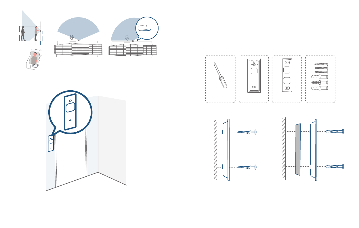
1.76m(5’9”)
15°
1m
(40")
1.2m (48")
0.3m
(12")
Porta
Videocitofono
Porta
Videocitofono
Senza cuneo di montaggio da 15° Con cuneo di montaggio da 15°
2. Collocare la scheda di posizionamento dei fori per le viti contro la parete per
contrassegnare la posizione di montaggio.
3.4 Montare la staffa
In caso di montaggio del citofono su una supercie lignea, non occorre praticare dei
prefori. Utilizzare le viti in dotazione per ssare la staffa di montaggio alla parete. La
scheda di posizionamento dei fori per le viti indica la posizione dei fori per le viti.
Attrezzi richiesti: trapano elettrico, staffa di montaggio, cuneo di montaggio da 15°
(facoltativo), pacchetti di viti
Cacciavite a stella
(non in dotazione)
Parete
Montaggio
Staffa
Staffa di montaggio
(collegata al cuneo di
montaggio da 15°)
Cuneo di montaggio
da 15° (facoltativo)
Parete
Montaggio
Cuneo
Senza cuneo di montaggio da 15° Con cuneo di montaggio da 15°
Italiano Italiano
128
Pacchetti di viti (viti e
ancoraggi sono inclusi)
Montaggio
Staffa
129
Page 67

Se si decide di installare il citofono su una supercie di materiali duri come mattoni,
calcestruzzo o stucco:
Praticare 2 fori usando la scheda di posizionamento dei fori per le viti con una
①
punta da 6 mm (15/64'').
Inserire gli ancoraggi in dotazione e utilizzare le viti lunghe per ssare la staffa
②
di montaggio alla parete.
Attrezzi richiesti: trapano elettrico, punta da 6 mm (15/64''), staffa di
montaggio, cuneo di montaggio da 15° (facoltativo), pacchetti di viti
Trapano elettrico
(non in dotazione)
Punta da 6 mm (15/64'')
Staffa di montaggio
(collegata al cuneo di
montaggio da 15°)
Cuneo di montaggio
da 15° (facoltativo)
Pacchetti di viti (viti e
ancoraggi sono inclusi)
Parete
Montaggio
Staffa
Montaggio
Cuneo
Montaggio
Staffa
Parete
Senza cuneo di montaggio da 15° Con cuneo di montaggio da 15°
2 2
1
Italiano Italiano
130
131
Page 68
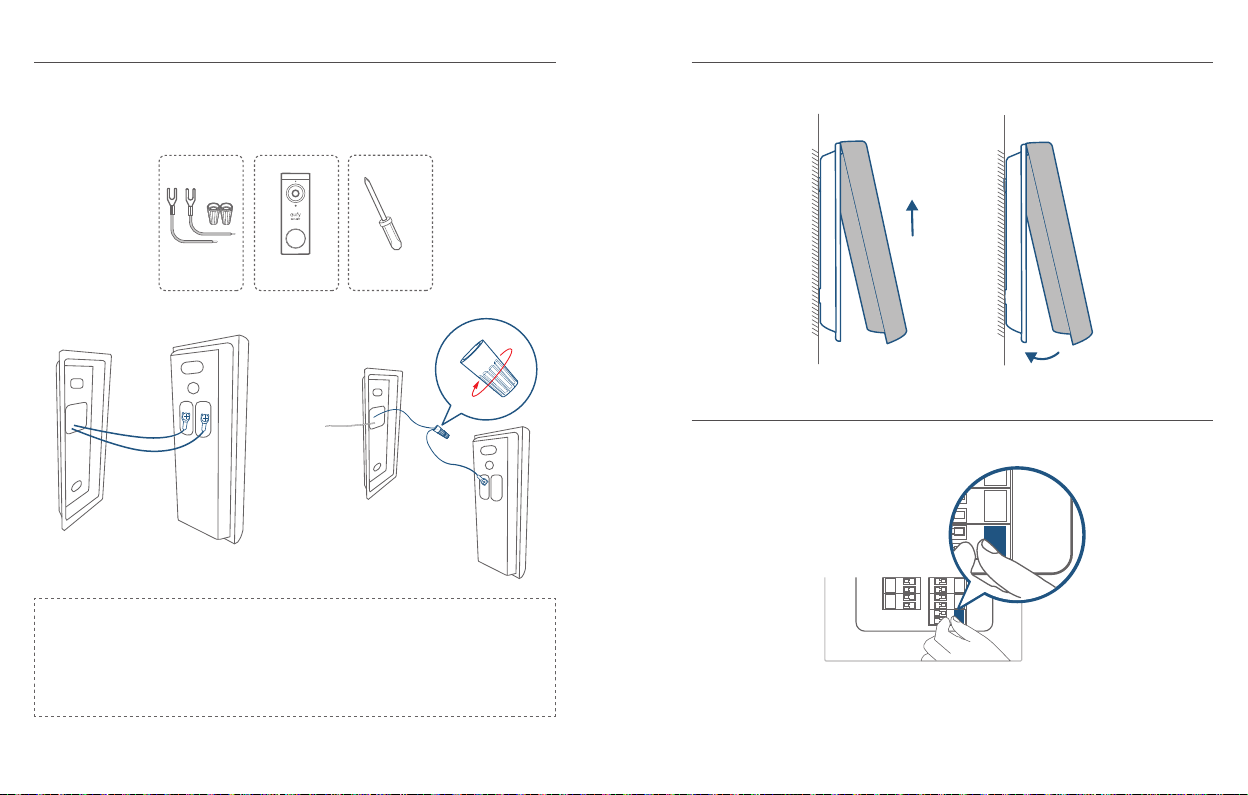
3.5 Collegare i cavi al citofono
ON
3.6 Montare il citofono sulla staffa
Collegare i cavi ai terminali che si trovano sul retro del citofono, quindi serrare le viti
dei terminali. Il lo può essere collegato a qualsiasi terminale.
Attrezzi richiesti: cavi e cappucci (facoltativi), videocitofono, cacciavite a stella
Cavi di estensione e
cappucci (facoltativi)
Videocitofono 2K (cablato)
Modello: T8210
Cacciavite a stella
(non in dotazione)
Nota:
•
Per evitare cortocircuiti, accertarsi che i li non si tocchino dopo averli collegati
ai terminali.
•
Se i li sono troppo corti, utilizzare i cavi di estensione e i cappucci in dotazione
per allungarli. In alternativa, utilizzare del nastro isolante nel caso in cui non vi sia
più spazio per i cappucci sulla parete.
Allineare il citofono lungo la parte superiore e poi agganciarlo alla parte inferiore.
3.7 Ripristinare l’alimentazione
Riposizionare l’interruttore dell’alimentazione principale su ON.
ON
Il montaggio è terminato!
Se si desidera rimuovere il citofono o ricaricarlo, fare riferimento alle sezioni
corrispondenti.
Italiano Italiano
132
133
Page 69

WAT ZIT ER IN DE DOOS?
QSG
INHOUDS-
OPGAVE
Wat Zit Er In De Doos?
Productoverzicht
De Werking Van Het Systeem
De Homebase Aansluiten
Het Systeem Instellen
De Voedingsoptie Bepalen
135 144
137 146
139 149
140 150
141 151
142 152
Een Geschikte Montageplek
Vinden
De Beugel Monteren
De Deurbel Monteren
De Deurbel Loskoppelen
De Deurbel Opladen
De Deurbel Voeden Met
Bestaande Deurbelbedrading
Voor de installatie van de videodeurbel
Videodeurbel 2K
(op batterijen)
Model: T8210
FCC-ID: 2AOKB-T8210
IC: 23451-T8210
Brug voor
oorspronkelijke
gong (optioneel)
Schroefpakketten
(reserveschroeven en
-pluggen meegeleverd)
Montagebeugel
Verlengdraden en
draadmoeren (optioneel)
Snelstartgids
Positioneringskaart
voor schroefgaten
USB-oplaadkabel
15° montagewig
(optioneel)
Ontgrendelingspin
voor de deurbel
Nederlands Nederlands
134
135
Page 70
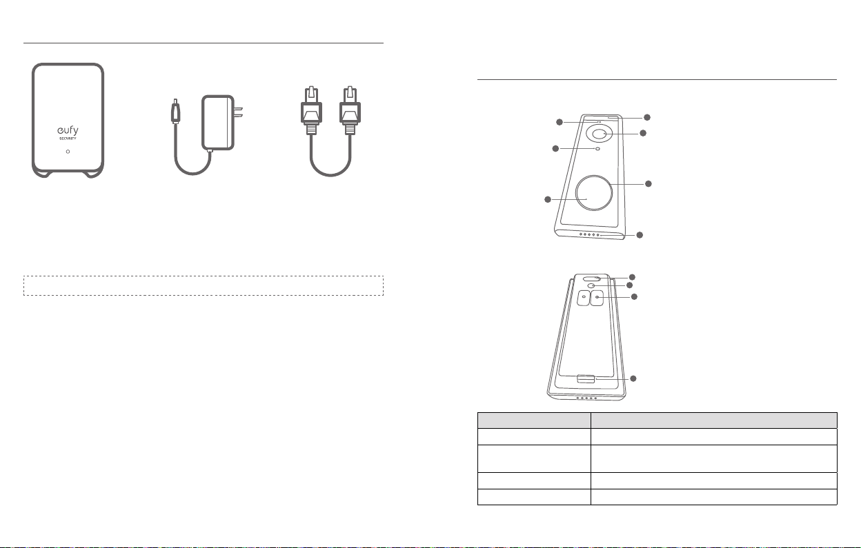
Voor de installatie van de HomeBase 2
Model: HomeBase 2 Voedingsadapter
voor de HomeBase 2
Ethernetkabel voor
de HomeBase 2
PRODUCTOVERZICHT
Videodeurbel (op batterijen)
Vooraanzicht:
2
4
6
1
3
5
1. Bewegingssensor
2. Microfoon
3. Cameralens
4. Omgevingslichtsensor
5. Led-ring
6. Deurbelknop
7. Luidspreker
FCC-ID: 2AOKB-T8010
IC: 23451-T8010
Opmerking: de stekker kan per regio verschillen.
Achteraanzicht:
7
1
2
3
1. Micro-USB-oplaadpoort
2. SYNC/RESET-knop
3. Voedingsklemmen voor
bestaande deurbelbedrading
(optioneel)
4. Loskoppelmechanisme
4
Bediening Instructies
Inschakelen Druk op de SYNC-knop
Voeg de deurbel toe aan
HomeBase
Houd de SYNC-knop ingedrukt totdat u een pieptoon
hoort
De deurbel uitschakelen Druk binnen 3 seconden snel 5 keer op de SYNC-knop.
De deurbel resetten Houd de SYNC-knop 10 seconden ingedrukt.
Nederlands Nederlands
136
137
Page 71
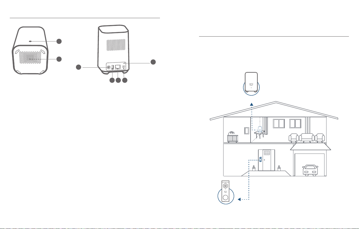
Videodeurbel (op batterijen)
1
2
3
4 5 6
DE WERKING VAN HET SYSTEEM
DE WERKING VAN HET SYSTEEM
Het videodeurbelsysteem bestaat uit 2 delen. Eén deel is de videodeurbel bij uw deur.
Het andere is de HomeBase in uw huis.
De videodeurbel detecteert beweging op uw veranda en stelt u in staat de deur altijd
7
en overal te open te doen. De HomeBase slaat videoclips op in het ingebouwde
opslaggeheugen. Als iemand aanbelt, krijgen de mensen in huis een melding.
1. Status-led
2. Luidspreker
3. Voedingspoort
4. USB-poort
Nederlands Nederlands
138
5. Ethernetpoort
6. SYNC/ALARM OFF-knop
7. Resetknop
Deurbelgong
Videodeurbel
139
Page 72

STAP 1 DE HOMEBASE AANSLUITEN
STAP 2 HET SYSTEEM INSTELLEN
De HomeBase 2 verbinden met het internet
1. Schakel de HomeBase 2 in en gebruik vervolgens de meegeleverde ethernetkabel
om de HomeBase 2 aan te sluiten op uw thuisrouter.
2. De led-indicator wordt blauw (dit kan 1 minuut duren) wanneer HomeBase 2
klaar is voor de installatie.
De app downloaden en het systeem instellen
Download de eufy Security-app uit de App Store (iOS-apparaten) of Google Play
(Android-apparaten).
Meld u aan voor een Eufy Security-account en volg de instructies op het scherm om
het instellen te voltooien.
Nederlands Nederlands
140
141
Page 73

STAP 3 DE VOEDINGSOPTIE BEPALEN
Optie 1 - batterijvoeding
1. Als u geen bestaande deurbelbedrading bij de voordeur hebt, gebruikt u de
ingebouwde batterij.U bent vrij om de plaatsing van de deurbel te bepalen en de
montage is eenvoudig en snel.
2. Wanneer de batterij van de deurbel bijna leeg is, moet u deze loskoppelen en
opladen.
3. Als u deze optie kiest, gaat u naar S
Opmerking: de batterijduur is afhankelijk van het gebruik.In de meest voorkomende
gevallen kan een deurbel tot 10 gebeurtenissen per dag vastleggen, waarbij elke
opname gemiddeld 20 seconden duurt.In dit scenario is de batterijduur maximaal 6
maanden.
VINDEN
.
6 maanden
TAP 4 EEN GESCHIKTE MONTAGEPLEK
Optie 2 - voeding met deurbelbedrading
1. Als u bestaande en werkende deurbelbedrading bij de voordeur hebt, wordt de
deurbel constant gevoed door de draden.U hoeft de batterij van de deurbel in dit
geval dus niet los te koppelen en op te laden na de installatie.
2. Omdat de deurbel met de draden is verbonden, bent u beperkt in het kiezen van
een geschikte plaatsing voor de deurbel.
3. Als u deze optie kiest, gaat u naar bijlag
deurbelbedrading
.
e 3 de deurbel voeden met
8 - 24V AC-deurbelbedrading
Nederlands Nederlands
142
143
Page 74

STAP 4 EEN GESCHIKTE
15°
MONTAGEPLEK VINDEN
Een geschikte montageplek vinden
Neem de videodeurbel mee naar uw voordeur en bekijk tegelijkertijd de liveweergave
in de app.Zoek een plaats die u het gewenste gezichtsveld biedt.
Houd rekening met de onderstaande factoren:
1. Controleer of u de bestaande gaten en pluggen in de muur of het deurkozijn kunt
hergebruiken.
2. Als u de deurbel dicht bij een zijmuur wilt plaatsen, zorgt u ervoor dat de muur
niet in het gezichtsveld verschijnt.Anders wordt IR-licht gereecteerd en wordt
nachtzicht wazig.
3. Als u de montagegaten voor het eerste boort, is de aanbevolen montagehoogte 1,2
m vanaf de grond.
4. Als u meer wilt zien aan een specieke zijde, gebruikt u de 15° montagewig als
extra montagebeugel.
Plaats de positioneringskaart voor schroefgaten tegen de muur om de positie te
markeren.
1.76m(5’9”)
1m
(40")
Nederlands Nederlands
144
1.2m (48")
0.3m
(12")
Deur
Videodeurbel
Zonder 15° montagewig Met 15° montagewig
Deur
Videodeurbel
145
Page 75
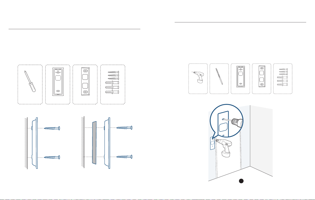
STAP 5 DE BEUGEL MONTEREN
De deurbel monteren op een houten oppervlak
Als u de deurbel op een houten oppervlak monteert, hoeft u geen boorgaten voor
te boren.Gebruik de meegeleverde schroeven om de montagebeugel aan de muur
te bevestigen. De positioneringskaart voor schroefgaten geeft de plaatsing van de
schroefgaten aan.
Wat u nodig hebt: Schroevendraaier, montagebeugel, 15° montagewig (optioneel),
schroefpakketten
De deurbel monteren op oppervlakken gemaakt van
harde materialen
1. Als u de deurbel monteert op een oppervlak dat is gemaakt van harde materialen,
zoals baksteen, beton of stucwerk, gebruikt u een boortje van 6 mm om 2 gaten
door de positioneringskaart voor schroefgaten te boren.
2. Steek de meegeleverde pluggen in de gaten en gebruik vervolgens de
meegeleverde lange schroeven om de montagebeugel aan de muur te bevestigen.
Wat u nodig hebt: Boormachine, boortje van 6 mm, montagebeugel, 15°
montagewig (optioneel), schroefpakketten
Power Drill
(not provided)
Kruiskopschroevendraaier
(niet meegeleverd)
Muur
Montage-
beugel
Zonder 15° montagewig Met 15° montagewig
Nederlands Nederlands
146
Montagebeugel
(bevestigd aan 15°
montagewig)
15° montage-
wig (optioneel)
Muur
Montage-
Wig
Schroefpakketten
(reserveschroeven
and anchors are included.)
Montage-
beugel
Boortje van 6 mm
Montagebeugel
(bevestigd aan 15°
montagewig)
1
15° montage-
wig (optioneel)
Schroefpakketten
(reserveschroeven
and anchors are included.)
147
Page 76

Muur
Montage-
Muur
Montage-
beugel
Zonder 15° montagewig Met 15° montagewig
2 2
Montage-
Wig
beugel
STAP 6 DE DEURBEL MONTEREN
De deurbel monteren
Lijn de deurbel uit aan de bovenkant en klik de onderkant vervolgens vast.Druk
omlaag totdat de deurbel op zijn plaats klikt.
U bent klaar!
Als u de deurbel wilt loskoppelen of wilt opladen, raadpleegt u de volgende delen van
deze handleiding.
Nederlands Nederlands
148
149
Page 77

BIJLAGE 1 DE DEURBEL LOSKOPPELEN
BIJLAGE 2 DE DEURBEL OPLADEN
De deurbel loskoppelen
1. Gebruik de meegeleverde ontgrendelingspin voor de deurbel als u de deurbel los
wilt koppelen van de montagebeugel.
2. Houd het gat aan de onderkant van de deurbel ingedrukt en til de onderkant van
de deurbel daarna op om deze van de beugel te halen.
Wat u nodig hebt: Ontgrendelingspin voor de deurbel
Deurbel
Ontgrendelingspin
De deurbel opladen
Led-indicatie
Oplaadtijd 6 uur van 0% tot 100%
Opladen: Brandt oranje
Volledig opgeladen: Brandt cyaan
Nederlands Nederlands
150
151
Page 78

BIJLAGE 3 DE DEURBEL VOEDEN MET
OFF
BESTAANDE DEURBELBEDRADING
3.1 Controleer of de deurbelbedrading werkt
1. Gebruik de bestaande deurbel om aan te bellen en te controleren of de deurbel
werkt.Als de deurbel geen geluid maakt, is de bedrading van uw deurbel mogelijk
defect.Gebruik de eigen batterij van de videodeurbel om de deurbel te voeden of
raadpleeg een elektricien om de bedrading te repareren.
2. Schakel de stroom uit bij de stroomonderbreker.Schakel de lichten in/uit om te
controleren of de elektriciteit in uw huis goed is uitgeschakeld.
OFF
Wees altijd voorzichtig bij de omgang met elektriciteitskabels.Als u het
niet prettig vindt om de bekabeling zelf te installeren, raadpleegt u een
gekwaliceerd elektricien.
3.2 De bestaande deurbelknop loskoppelen
Als u al bestaande bedrading voor de deurbel hebt:
1. Verwijder de bestaande deurbelknop met een kruiskopschroevendraaier (niet
meegeleverd).
2. Trek de twee draden tijdens het verwijderen van de deurbel voorzichtig uit de
deurbel.Maak de uiteinden van de draden recht indien nodig.
Wat u nodig hebt: Kruiskopschroevendraaier
Kruiskopschroevendraaier
(User provides it.)
3.3 Een geschikte montageplek vinden
1. Bepaal waar u de deurbel gaat monteren.Houd rekening met de onderstaande
factoren:
Controleer of u de bestaande gaten en pluggen in de muur of het deurkozijn
①
kunt hergebruiken.
Als u de montagegaten voor het eerste boort, is de aanbevolen
②
montagehoogte 1,2 m vanaf de grond.
Nederlands Nederlands
152
153
Page 79

Als u meer wilt zien aan een specieke zijde, gebruikt u de 15° montagewig
15°
③
als extra montagebeugel.
1.76m(5’9”)
1m
(40")
1.2m (48")
0.3m
(12")
Deur
Videodeurbel
Deur
Videodeurbel
Zonder 15° montagewig Met 15° montagewig
2. Plaats de positioneringskaart voor schroefgaten tegen de muur om de positie te
markeren.
3.4 De beugel monteren
Als u de deurbel op een houten oppervlak monteert, hoeft u geen boorgaten voor
te boren.Gebruik de meegeleverde schroeven om de montagebeugel aan de muur
te bevestigen.De positioneringskaart voor schroefgaten geeft de positie van de
schroefgaten aan.
Wat u nodig hebt: Boormachine, montagebeugel, 15° montagewig (optioneel),
schroefpakketten
Kruiskopschroevendraaier
(User provides it.)
Montagebeugel
(bevestigd aan 15°
montagewig)
15° montage-
wig (optioneel)
Schroefpakketten
(reserveschroeven
and anchors are included.)
Muur
Muur
Montage-
beugel
Montage-
Wig
Zonder 15° montagewig Met 15° montagewig
Nederlands Nederlands
154
Montage-
beugel
155
Page 80
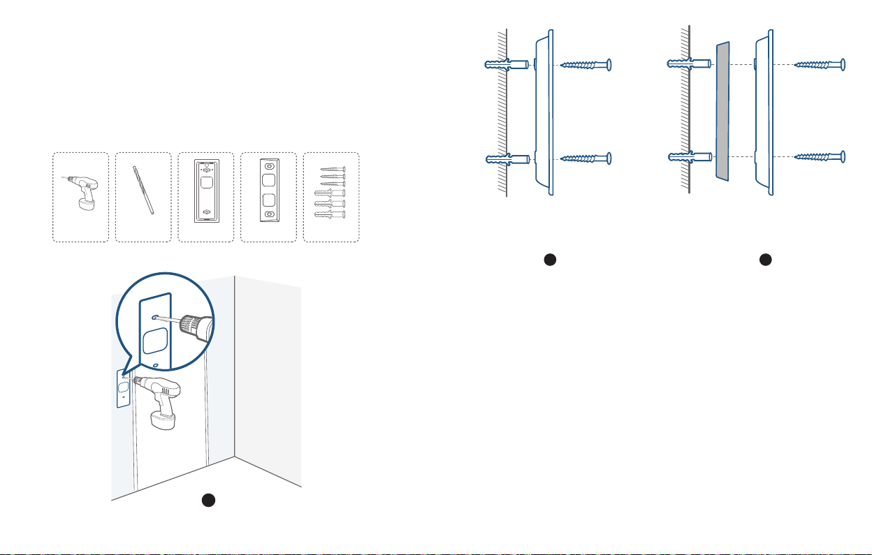
Als u de deurbel monteert op een oppervlak gemaakt van harde materialen, zoals
baksteen, beton, stucwerk:
Gebruik een boortje van 6 mm om 2 gaten door de positioneringskaart voor
①
schroefgaten te boren.
Steek de meegeleverde pluggen in de gaten en gebruik vervolgens de
②
meegeleverde lange schroeven om de montagebeugel aan de muur te bevestigen.
Wat u nodig hebt: Boormachine, boortje van 6mm, montagebeugel, 15°
montagewig (optioneel), schroefpakketten
Boormachine
(niet meegeleverd)
Boortje van 6 mm
Montagebeugel
(bevestigd aan 15°
montagewig)
15° montage-
wig (optioneel)
Schroefpakketten
(reserveschroeven
and anchors are included.)
Muur
Montage-
Muur
Montage-
beugel
Montage-
Wig
beugel
Zonder 15° montagewig Met 15° montagewig
2 2
1
Nederlands Nederlands
156
157
Page 81
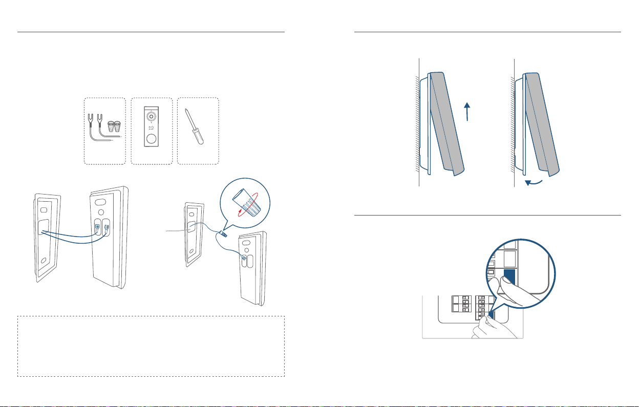
3.5 De deurbelbedrading aansluiten op de deurbel
ON
3.6 De deurbel monteren op de beugel
Sluit de draden aan op de klemmen op de achterkant van de deurbel en draai
vervolgens de klemschroeven vast. De draad mag op een willekeurige klem worden
aangesloten.
Wat u nodig hebt: Draden en draadmoeren (optioneel), videodeurbel,
kruiskopschroevendraaier
Verlengdraden en
draadmoeren (optioneel)
Videodeurbel 2K (bekabeld)
Model: T8210
Kruiskopschroevendraaier
(User provides it.)
Opmerking:
•
Om kortsluiting te voorkomen, moet u ervoor zorgen dat de draden elkaar niet
raken nadat ze op de klemmen zijn aangesloten.
•
Als de draden te kort zijn, gebruikt u de meegeleverde verlengdraden en
draadmoeren om de draden langer te maken.Als er op de muur geen ruimte is
voor draadmoeren, gebruikt u in plaats daarvan tape voor elektrische bedrading.
Lijn de deurbel uit aan de bovenkant en klik de onderkant vervolgens vast.
3.7 De stroom weer inschakelen
Schakel de hoofdstroomonderbreker weer in.
ON
U bent klaar!
Als u de deurbel wilt loskoppelen of opladen, raadpleegt u de betreffende delen van
deze handleiding.
Nederlands Nederlands
158
159
Page 82

ESTÁ INCLUÍDO
QSG
TABLE OF
CONTENTS
Está Incluído
Descrição Do Produto
Como Funciona O Sistema
Ligar A Homebase
Congurar O Sistema
Determinar A Opção De
Alimentação
161 170
163 172
165 175
166 176
167 177
168 178
Encontrar Um Local Para A
Instalação
Instalar O Suporte
Instalar A Campainha
Remover A Campainha
Recarregar A Campainha
Ligar A Campainha Com Fios
Existentes
Para a instalação do Videoporteiro
Videoporteiro
2K(A bateria)
Modelo: T8210
ID da FCC: 2AOKB-T8210
IC: 23451-T8210
Jumper para a
campainha original
(opcional)
Pacotes de parafusos
(parafusos e âncoras
sobressalentes incluídos)
Suporte de
instalação
Fios de extensão e
porcas de os (opcional)
Guia de início rápido
posicionamento dos
orifícios para parafuso
carregamento USB
Cartão de
Cabo de
Cunha de instalação
de 15° (opcional)
Pino de remoção da
campainha
Português Português
160
161
Page 83
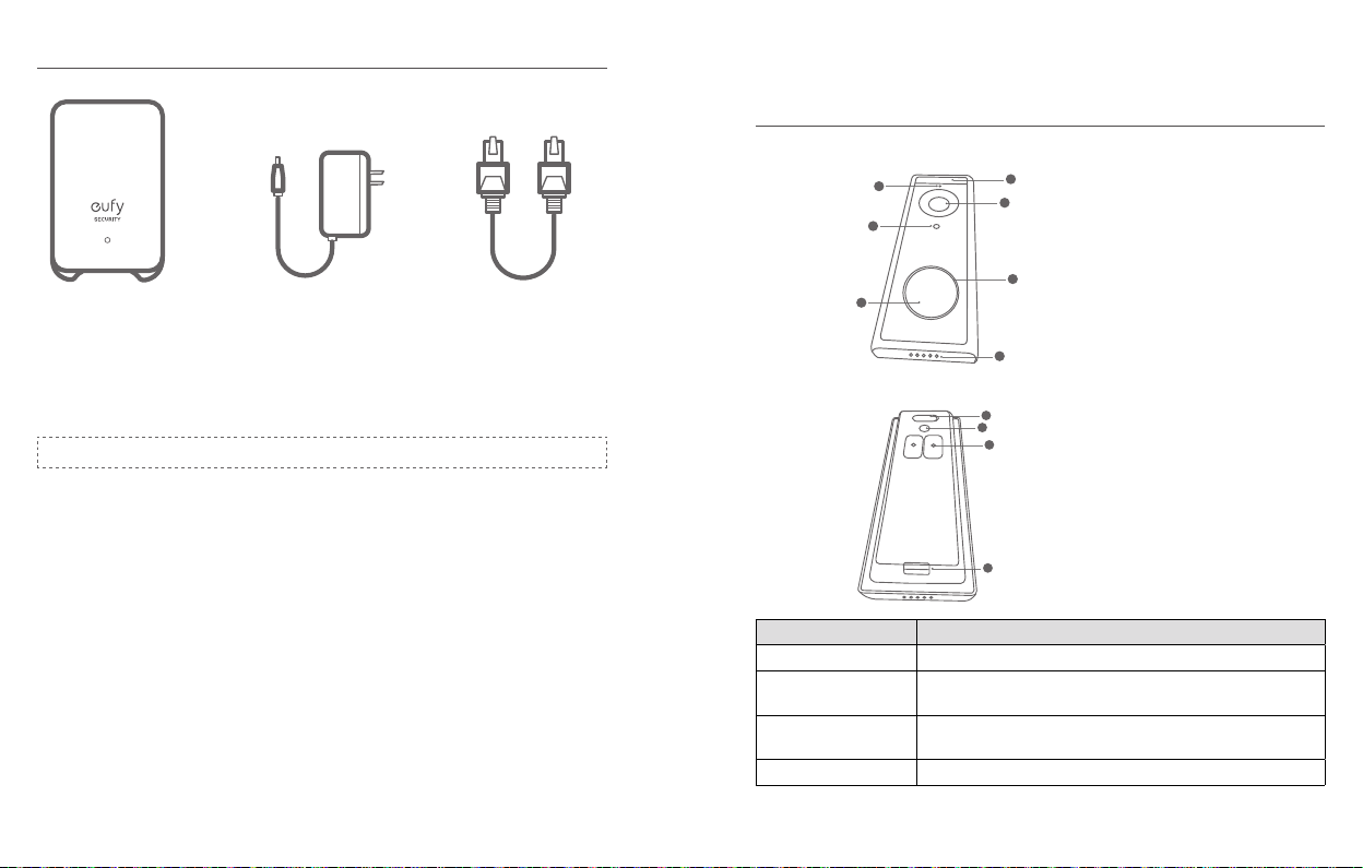
Para a instalação da HomeBase 2
Modelo:
HomeBase 2
ID da FCC: 2AOKB-T8010
IC: 23451-T8010
Nota: A cha de alimentação poderá variar consoante as regiões diferentes.
Adaptador de
alimentação da
HomeBase 2
Cabo de Ethernet da
HomeBase 2
DESCRIÇÃO DO PRODUTO
Videoporteiro (A bateria)
Parte da frente:
2
4
6
Parte de trás:
Operação Como fazer
Ligar Prima e liberte o botão SYNC
Adicione a campainha
da porta à HomeBase
Prima continuamente o botão SYNC até ouvir um aviso
sonoro
Desligue a campainha Prima rapidamente 5 vezes o botão SYNC dentro de 3
segundos.
Repor a campainha Prima continuamente o botão SYNC durante 10 segundos.
1
3
1. Sensor de movimento
2. Microfone
3. Lente da câmara
4. Sensor de luz ambiente
5. Anel de LED
5
6. Botão da campainha
7. Altifalante
7
1
2
3
1. Porta de carregamento micro-USB
2. Botão SYNC/RESET
3. Terminais de alimentação para os os
da campainha existentes (opcional)
4. Retirar o mecanismo
4
Português Português
162
163
Page 84

Videoporteiro (A bateria)
COMO FUNCIONA O SISTEMA
COMO FUNCIONA O SISTEMA
1
2
1. LED de estado
2. Altifalante
3. Porta de alimentação
4. Porta USB
3
4 5 6
5. Porta de Ethernet
6. Botão SYNC/ALARM OFF
7. Botão de reposição
O sistema de Videoporteiro inclui 2 partes. Uma é o videoporteiro na sua porta. A
outra é a HomeBase na sua residência.
O videoporteiro deteta movimento na sua entrada e permite-lhe atender a porta
7
em qualquer altura e em qualquer lugar. A HomeBase armazena clipes de vídeo no
armazenamento incorporado. Quando alguém toca à campainha, as pessoas dentro
de casa serão noticadas.
Campainha
Videoporteiro
Português Português
164
165
Page 85
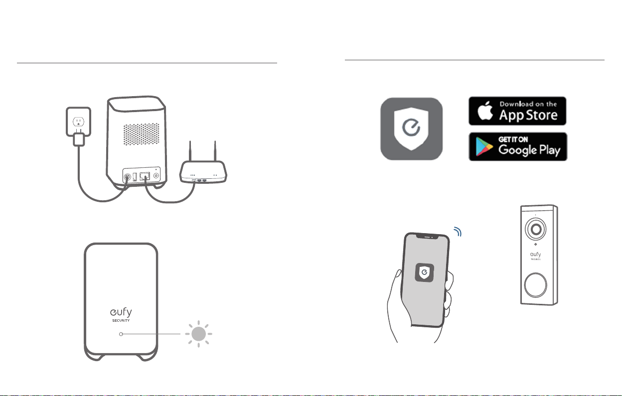
PASSO 1 LIGAR A HOMEBASE
PASSO 2 CONFIGURAR O SISTEMA
Ligar a HomeBase 2 à Internet
1. Ligue a HomeBase 2, em seguida, utilize o cabo de Ethernet fornecido para ligar a
HomeBase 2 ao seu router doméstico.
2. O indicador LED ca azul (isto poderá demorar 1 min.) quando a HomeBase 2
estiver pronta para congurar.
Transferir a aplicação e configurar o sistema
Transfira a aplicação Eufy Security a partir da App Store (dispositivos iOS) ou da
Google Play (dispositivos Android).
Registe uma conta Eufy Security, em seguida, siga as instruções no ecrã para concluir
a conguração.
Português Português
166
167
Page 86
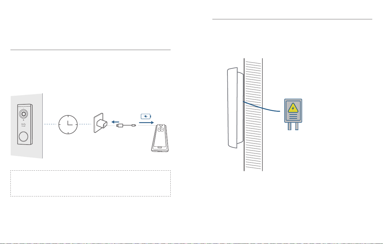
PASSO 3 DETERMINAR A OPÇÃO DE
ALIMENTAÇÃO
Opção 1 - Alimentação a bateria
1. Se não tiver uma ligação por os na porta da frente, utilize a bateria incorporada.
Pode determinar a posição da campainha e a instalação é fácil e rápida.
2. Quando o nível da bateria da campainha estiver baixo, deve retirá-la e carregá-la.
3. Se escolher esta opção, vá para o PASSO
A INSTALAÇÃO
Nota: A duração da bateria varia consoante a utilização. Na maioria dos casos
comuns, uma campainha poderá ter até 10 eventos por dia, e cada gravação dura
cerca de 20 segundos. Neste cenário, a duração da bateria da campainha pode ser
até 6 meses.
.
6 meses
4 ENCONTRAR UM LOCAL PARA
Opção 1I - Optrica com fios
1. Se tiver uma ligação por os para campainha na porta da frente, a campainha será
constantemente alimentada por o. Por isso, não precisa retirá-la e carregá-la
depois de a instalar.
2. Como a campainha é alimentada por os, a posição de instalação é limitada.
3. Se escolher esta opção, vá para o
Anexo 3 Ligar a campainha com fios
Cablagem da campainha 8 24 V CA
.
Português Português
168
169
Page 87

PASSO 4 ENCONTRAR UM LOCAL
15°
PARA A INSTALAÇÃO
Encontrar um local para a instalação
Leve o teleporteiro para a porta da frente e, ao mesmo tempo, verifique a
visualização em direto na aplicação. Encontre um local de onde consiga obter o
campo de visão pretendido.
Considere os fatores abaixo:
1. Verique se pode reutilizar os orifícios e âncoras existentes na parede ou na
moldura da porta.
2. Se quiser colocar a campainha junto a uma parede lateral, certique-se de esta
não aparece no campo de visão. Caso contrário, a luz de IV poderá ser reetida e
a visão noturna tornar-se-á desfocada.
3. Se perfurar os orifícios de instalação pela primeira vez, a altura de instalação
recomendada é de 1,2 m de altura do chão.
4. Utilize o calço de instalação como suporte de instalação adicional se quiser ver
mais de um lado especíco.
Coloque o cartão de posicionamento de orifícios para parafusos contra a parede para
marcar a posição.
1.76m(5’9”)
1m
(40")
Português Português
170
1.2m (48")
0.3m
(12")
Porta
Videoporteiro
Sem a Cunha de instalação de 15° Com a Cunha de instalação de 15°
Porta
Videoporteiro
171
Page 88

PASSO 5 INSTALAR O SUPORTE
Instalar a campainha em superfícies fabricadas em
materiais duros
Instalar a campainha numa superfície de madeira
Se estiver a instalar a campainha numa superfície de madeira, não precisa perfurar
antecipadamente os orifícios piloto. Utilize os parafusos fornecidos para fixar o
Suporte de instalação à parede. O cartão de posicionamento de orifícios para
parafuso indica a posição dos mesmos.
O que é necessário: Chave de parafusos, Suporte de instalação, Cunha de instalação
de 15° (opcional), conjuntos de parafusos
Chave de parafusos Phillips
(não fornecida)
Parede
Suporte de
Instalação
Sem a Cunha de instalação de 15° Com a Cunha de instalação de 15°
Suporte de instalação
(xado à cunha de instalação
de 15°)
Cunha de
instalação de 15° (opcional)
Parede
Suporte de
Pacotes de parafusos
(parafusos e âncoras
and anchors are included.)
Suporte de
Cunha
Instalação
1. Se estiver a instalar a campainha numa superfície fabricada num material duro,
como tijolo, betão, estuque, perfure 2 orifícios com a ajuda do Cartão de
posicionamento de orifícios para parafuso com uma broca de 6 mm.
2. Insira as âncoras fornecidas e, em seguida, utilize os parafusos compridos para
xar o Suporte de instalação à parede.
O que é necessário: Broca elétrica (6mm), Suporte de instalação, Cunha de
instalação de 15° (opcional), pacotes de parafusos
Power Drill
(not provided)
Broca de 6 mm
Suporte de instalação
(xado à cunha de instalação
de 15°)
1
Cunha de
instalação de 15° (opcional)
Pacotes de parafusos
(parafusos e âncoras
and anchors are included.)
Português Português
172
173
Page 89
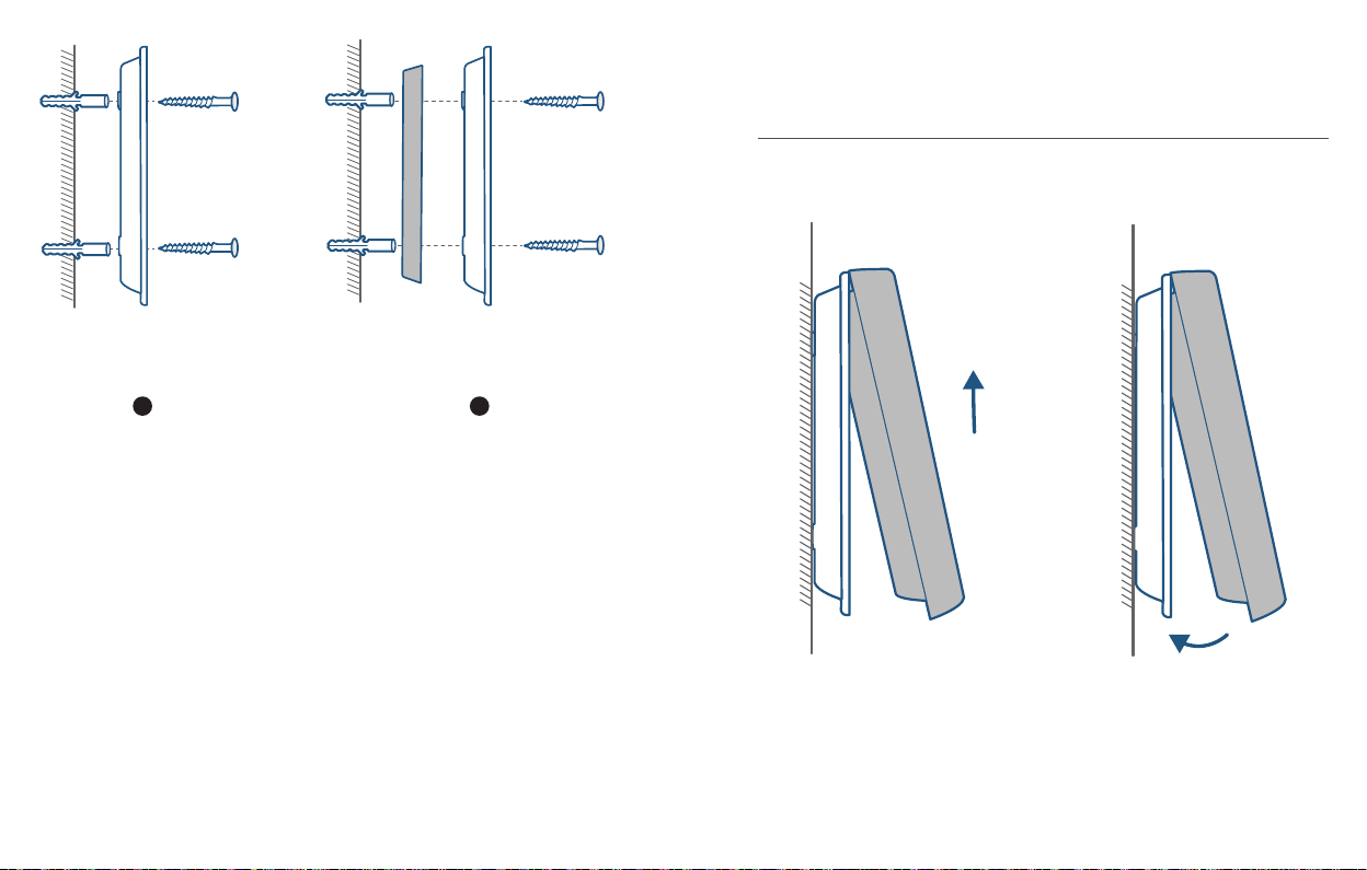
Parede
Suporte de
Parede
Suporte de
Instalação
Sem a Cunha de instalação de 15° Com a Cunha de instalação de 15°
2 2
Cunha
Suporte de
Instalação
PASSO 6 INSTALAR A CAMPAINHA
Instalar a campainha
Alinhe a parte de cima da campainha e, em seguida, encaixe a parte de baixo.
Pressione na mesma até que se encaixe no lugar.
Está pronta!
Se quiser remover a campainha ou recarregá-la, consulte as seguintes secções.
Português Português
174
175
Page 90

ANEXO 1 REMOVER A CAMPAINHA
Remover a campainha
ANEXO 2 RECARREGAR A
CAMPAINHA
1. Utilize o pino de remoção da campainha fornecido se quiser remover a campainha
do suporte de instalação.
2. Pressione continuamente o orifício na parte de baixo da campainha e, em seguida,
levante a parte de baixo para a retirar.
O que é necessário: Pino de remoção da campainha
Pino de remoção
da campainha
Recarregar a campainha
Indicação do LED
Tempo de carregamento 6 horas de 0% a 100%
A carregar: Laranja sólido
Totalmente carregada: Azul sólido
Português Português
176
177
Page 91
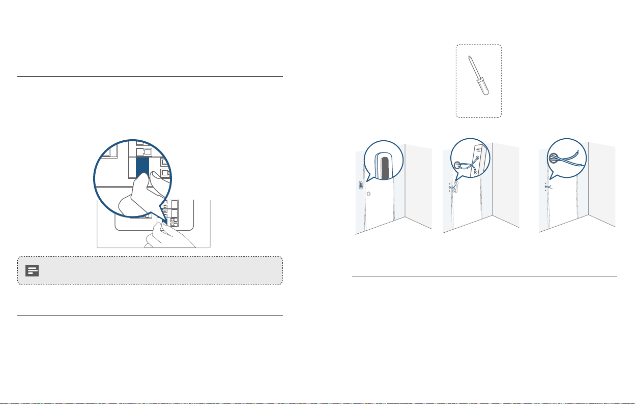
ANEXO 3 LIGAR A CAMPAINHA COM
OFF
FIOS EXISTENTES
3.1 Verificar se os fios da campainha estão a funcionar
1. Toque a campainha existente para vericar se funciona. Se a campainha não tocar,
os os da campainha poderão estar com problemas. Ligue a campainha com a
própria bateria ou consulte um eletricista para arranjar os os.
2. Desligue a alimentação no disjuntor. Ligue/desligue as luzes de casa para se
certicar de que a eletricidade na sua habitação está realmente cortada.
OFF
O que é necessário: Chave de parafusos Phillips
Chave de parafusos Phillips
(User provides it.)
Tenha sempre cuidado ao manusear os. Se não se sentir confortável
para fazer a instalação, peça a um eletricista qualicado para o fazer.
3.2 Remover o botão da campainha existente
Se já tiver uma cablagem para a campainha:
1. Remova o botão da campainha existente com uma chave de parafusos Phillips (não
fornecida).
2. Puxe com cuidado os dois os para fora quando retirar a campainha existente.
Endireite os os se necessário.
Português Português
178
3.3 Encontrar um local para a instalação
1. Determine a posição de instalação da campainha. Considere os fatores abaixo:
Verique se pode reutilizar os orifícios e âncoras existentes na parede ou na
①
moldura da porta.
Se perfurar os orifícios de instalação pela primeira vez, a altura de instalação
②
recomendada é de 1,2 m de altura do chão.
Utilize o calço de instalação como suporte de instalação adicional se quiser
③
ver mais de um lado especíco.
179
Page 92

1.76m(5’9”)
15°
1m
(40")
1.2m (48")
0.3m
(12")
Porta
Videoporteiro
Porta
Videoporteiro
Sem a Cunha de instalação de 15° Com a Cunha de instalação de 15°
2. Coloque o cartão de posicionamento de orifícios para parafusos contra a parede
para marcar a posição.
3.4 Instalar o suporte
Se estiver a instalar a campainha numa superfície de madeira, não precisa perfurar
antecipadamente os orifícios piloto. Utilize os parafusos fornecidos para fixar o
Suporte de instalação à parede. O Cartão de posicionamento dos orifícios para
parafuso indica a posição dos orifícios para os parafusos.
O que é necessário: Broca elétrica, Suporte de instalação, Cunha de instalação de
15° (opcional), conjuntos de parafusos
Chave de parafusos Phillips
(User provides it.)
Parede
Suporte de
Instalação
Suporte de instalação
(xado à cunha de instalação
de 15°)
Cunha de
instalação de 15° (opcional)
Parede
Suporte de
Cunha
Sem a Cunha de instalação de 15° Com a Cunha de instalação de 15°
Português Português
180
Pacotes de parafusos
(parafusos e âncoras
and anchors are included.)
Suporte de
Instalação
181
Page 93

Se estiver a instalar a campainha numa superfície fabricada em materiais duros, como
tijolo, betão, estuque:
Perfure 2 orifícios com a ajuda do Cartão de posicionamento dos orifícios
①
para parafuso com a broca de 6 mm.
Insira as âncoras fornecidas e, em seguida, utilize os parafusos compridos para
②
xar o Suporte de instalação à parede.
O que é necessário: Broca elétrica (6mm), Suporte de instalação, Cunha de
instalação de 15° (opcional), pacotes de parafusos
Broca elétrica
(não fornecida)
Broca de 6 mm
Suporte de instalação
(xado à cunha de instalação
de 15°)
Cunha de
instalação de 15° (opcional)
Pacotes de parafusos
(parafusos e âncoras
and anchors are included.)
Parede
Suporte de
Parede
Suporte de
Instalação
Cunha
Suporte de
Instalação
Sem a Cunha de instalação de 15° Com a Cunha de instalação de 15°
2 2
1
Português Português
182
183
Page 94

3.5 Ligar os fios da campainha à campainha
ON
3.6 Instalar a campainha no suporte
Ligue os os aos terminais na parte de trás da campainha e, em seguida, aperte os
parafusos dos terminais. Os os podem ser ligados a qualquer terminal.
O que é necessário: Fios e porcas para fios (opcional), Videoporteiro, Chave de
parafusos Phillips
Fios de extensão
e porcas de os (opcional)
Videoporteiro 2K (Com os)
Modelo: T8210
Chave de parafusos Phillips
(User provides it.)
Nota:
•
Para evitar o curto-circuito, certique-se de que os os não estão em contacto
uns com os outros depois de os ligar aos terminais.
•
Se os os forem demasiado curtos, utilize os os de extensão e as porcas dos
os fornecidos para os alongar. Utilize ta adesiva para os elétricos se não tiver
mais espaço na parede para porcas de os.
Alinhe a parte de cima da campainha e, em seguida, encaixe a parte de baixo.
3.7 Repor a alimentação
Volte a LIGAR o disjuntor principal.
ON
Está pronta!
Se quiser remover a campainha ou recarregá-la, consulte as secções correspondentes.
Português Português
184
185
Page 95

CUSTOMER SERVICE
• Warranty
12-month limited warranty
• Call Us
United States +1 (800) 988 7973 Mon-Fri 9AM-5PM (PT)
United Kingdom +44 (0) 1604 936 200 Mon-Fri 6AM-11AM (GMT)
Germany +49 (0) 69 9579 7960 Mo-Fr 6:00-11:00
• Email Us
Customer Support: support@eufylife.com
Anker Innovations Limited
Room 1318-19, Hollywood Plaza, 610 Nathan Road, Mongkok, Kowloon,
Hong Kong
 Loading...