

Eudyna FRM5N143DS User Manual
FEATURES
• Integrated Design Optimizes Performance at
High Bit Rates up to 10 Gb/s applications.
• -25 dBm Typical Sensitivity
• -7 dBm Overload Power (typ.)
• 27 dB Optical Return Loss (ORL)
• Integral Thermistor
• Simplifies Receiver Circuit Design
• Integrated HBT IC preamp
APPLICATIONS
This 80GHz gain bandwidth product APD detector with HBT preamp
is intended to function as an optical receiver for DWDM, SONET, SDH
optical fiber systems operating at 10Gb/s. This detector operates at both
1310 and 1550nm. The nominal 10kΩ integral thermistor allows accurate
monitoring of the APD temperature and facilitates the design of the APD
bias control circuit. It has a typical transimpedance (Zt) value of 1100Ω
The detector preamplifier is DC coupled and has a differential electrical output.
DESCRIPTION
The FRM5N143DS incorporates a high bandwidth InGaAs APD photo diode, a GaAs
HBT IC amplifier in a hermetically sealed butterfly type package. The APD is processed
with modern MOVPE techniques resulting in reliable performance over a wide range of
operating conditions. The lens coupling system and the single mode fiber are assembled
using Nd YAG welding. It has differential output with DC coupling.
1
Edition 1.1
July 2004
InGaAs-APD/Preamp
Receiver
FRM5N143DS
查询FRM5N143DS供应商

2
InGaAs-APD/Preamp
Receiver
FRM5N143DS
Parameter
Storage Temperature
Operating Temperature
Supply Voltage
APD Reverse Voltage
Symbol
T
stg
-40 to +85
0 to +70
-6 to 0
0 to VB (Note 1)
V
V
°C
°C
T
op
V
ss
V
R
APD Reverse Current
1.0 mA
I
R
Ratings Unit
ABSOLUTE MAXIMUM RATINGS (Tc=25°C)
Parameter Symbol
OPTICAL & ELECTRICAL CHARACTERISTICS (Tc=25°C, λ=1,550nm, Vss=-5.2V, unless
otherwise specified)
Unit
Limits
Max.
Power Supply Current
I
ss
mA110 130--
-
Optical Return Loss
ORL
dB--27
Min. Typ.
Test Conditions
APD Responsivity
R15 A/W-0.65 0.71,550nm, M=1
V
-5.2
-
Power Supply Voltage
V
ss
-4.94
-5.46
kΩ
10
Vss=0V
Thermistor Resistance
R
tr
10.5
9.5
Sensitivity
P
r
dBm-25 -24-
NRZ, 10Gb/s,
PRBS=2
23
-1,
B.E.R.=10
-10
,
VR is set at
optimum value
Maximum Overload
P
o
dBm--8 -7
NRZ, 10Gb/s,
PRBS=2
23
-1,
B.E.R.=10
-10
, M = 3
Bandwidth
BW GHz-7.5 8.0
RL=50Ω, M=9,
-3dB from 130MHz,
Pin = -20dBm
AC Transimpedance
Z
t
Ω
800 14001100
RL=50Ω,
f=130MHz,
Temperature Coefficient of VB
Γ
V/°C0.03 0.070.05(Note 2)
APD Breakdown Voltage
V
B
V20 3530ID=10µA
Note: (1) VB differs from device to device. VB data is attached to each devices.
(2) Γ=dVB/dTC
Vss=0V
Thermistor B Constant
BK4,0003,800 3,900
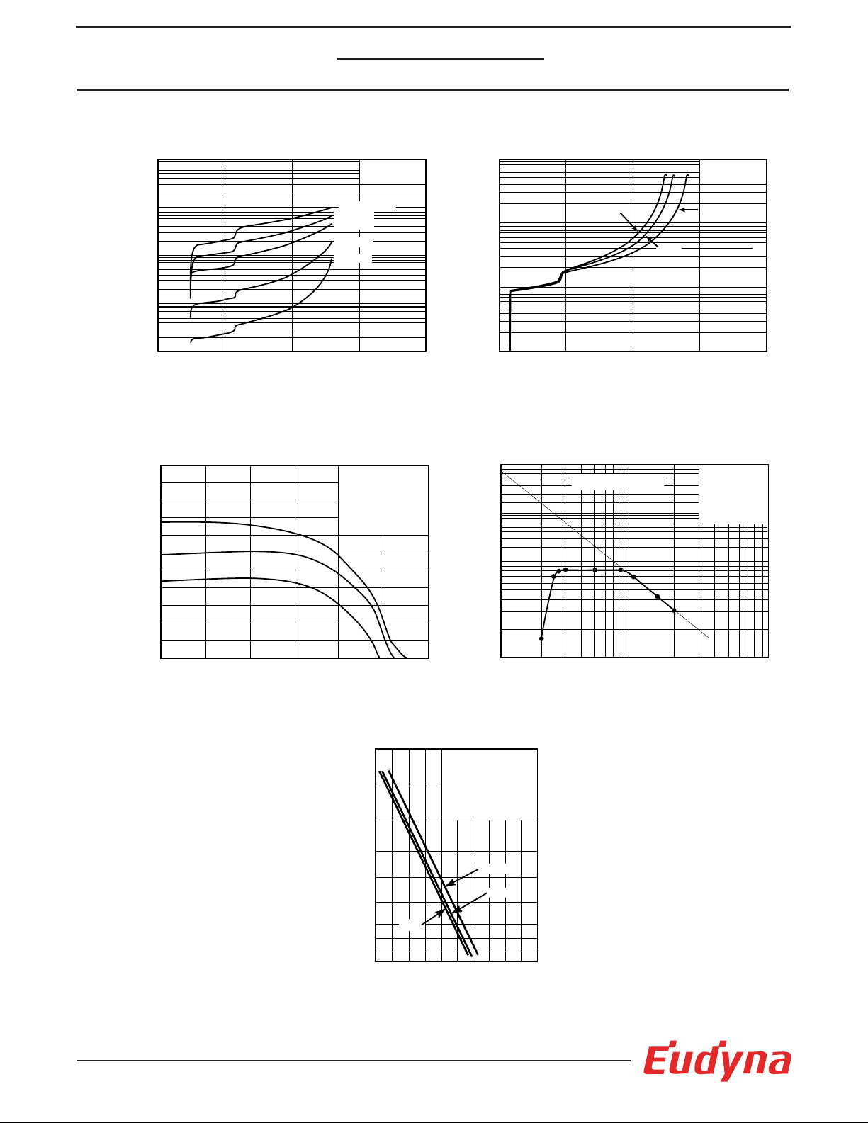
Fig. 5 Bit Error Rate
Bit Error Rate
Received Optical Power (dBm)
-26 -24 -22
70°C
0°C
25°C
-28-30
10
-12
10
-10
10
-8
10
-7
10
-6
10
-5
10
-4
10
-3
λ=1,550nm
9.95328Gb/s, NRZ
duty, mark density=0.5
Vss=-5.2V
M=optimum
Fig. 3 Relative Frequency Response
Relative Response (3dB/div)
Frequency, f (GHz)
15
10
M=9
M=6
M=3
5
1
Tc = 25°C
Vss=-5.2V
RL=50Ω
Pin=-27dBm
λ = 1,550nm
Fig. 2 Multiplication Characteristics
Multiplication Factor (M)
Reverse Voltage VR(V)
30 40
2010
0
0.1
1
10
100
Vss=-5.2V
Ipo=2µA
70°C
0°C
25°C
Photocurrent (A)
Tc=25°C
Vss=-5.2V
Fig. 1 Multiplication vs. Photocurrent
Reverse Voltage VR(V)
30 40
2010
1.0E-06
1.0E-05
1.0E-04
1.0E-03
1.0E-02
1
Pin = -7dBm
-10dBm
-13dBm
-20dBm
-27dBm
Bandwidth (GHz)
Tc=25°C
Vss=-5.2V
RL=50Ω
λ=1,550nm
Pin=-27dBm
Fig. 4 Multiplication vs. Bandwidth
Multiplication Factor (M)
100
10
1
10
100
1
GB Product 80GHz
3
InGaAs-APD/Preamp
Receiver
FRM5N143DS
 Loading...