

Page 1
GE Healthcare
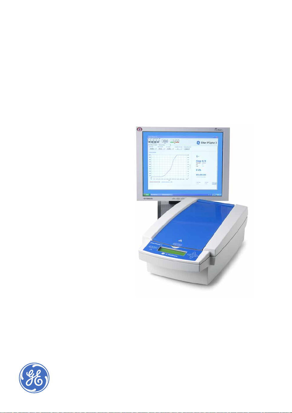
Ettan IPGphor 3
Instrument User Manual
Ettan
Page 2

Page 3

Important user information
All users must read this entire manual to fully understand
the safe use of Ettan IPGphor 3.
WARNING!
The following WARNING signs highlight instructions that
must be followed to avoid personal injury. It is important
not to continue until all stated conditions are met and
clearly understood.
WARNING! Lethal high voltage above 1 kV.
WARNING! Read the instructions to avoid
hazardous conditions.
CAUTION!
The Caution sign highlights instructions that
must be followed to avoid damage to the
product or other equipment. It is important not
to continue until all stated conditions are met
and clearly understood.
Note
The Note sign is used to indicate information
important for trouble-free and optimal use of
the product.
CE certification
This product meets the requirements of applicable CEdirectives. A copy of the corresponding Declaration of
Conformity is available on request.
The CE symbol and corresponding declaration of
conformity is valid for the instrument when it is:
– used as a stand-alone unit, or
– connected to other CE-marked GE Healthcare
instruments, or
– connected to other products recommended or
described in this manual, and
– used in the same state as it was delivered from GE
Healthcare except for alterations described in this
manual.
Page 4

Page 5

Contents
1 Ettan IPGphor 3 Isoelectric Focusing System function and
description
1.1 Unpacking ............................ ...................................... .................................. ........9
1.2 System components .......................................................................................9
1.3 Specifications ...................................................................................................17
1.4 Associated documentation ........................................................................18
2 Instrument set up
2.1 Placing the instrument ......................................... ........................................19
2.2 Power connection .............................................................. ............................19
2.3 Serial port connector for a computer connection ..........................20
3 Operating instructions
3.1 Power up ........................................................ .....................................................21
3.1.1 Ettan IPGphor 3 control panel......................................................................21
3.2 Using the Ettan IPGphor Cup Loading Manifold ..............................23
3.2.1 Rehydrating Immobiline DryStrip in the Rehydration Tray.............23
3.2.2 Positioning the manifold on the Ettan IPGphor 3.................................23
3.2.3 Positioning the IPG strips in the manifold................................................23
3.2.4 Sample cups.........................................................................................................24
3.2.5 Electrode paper wicks......................................................................................24
3.2.6 Positioning the electrodes..............................................................................24
3.2.7 Loading samples into the sample cups...................................................24
3.3 Using fixed-length Ettan IPGphor 3 strip holders ...................... ......25
3.3.1 Preparing the strip holder(s)..........................................................................25
3.3.2 Optional: Sample rehydration under voltage........................................27
3.3.3 Optional: Applying electrode pads prior to IEF......................................28
3.3.4 Optional: Applying sample after rehydration........................................28
3.3.5 Positioning the strip holders..........................................................................29
3.3.6 Closing the safety lid.........................................................................................30
3.4 Running a pre-programmed protocol from the PC ........................32
3.4.1 Ettan IPGphor 3 Control Software...............................................................32
3.4.2 Starting the Ettan IPGphor 3 Control Software.....................................33
3.5 Creating, editing, and running protocol programs from the
Ettan IPGphor 3 control panel ..................................................................37
3.5.1 Protocol parameters.........................................................................................37
3.5.2 Editing protocol parameters..........................................................................38
3.5.3 Starting isoelectric focusing from the Ettan IPGphor 3 control
panel........................................................................................................................44
3.5.4 Pausing or stopping a protocol................................................................ ... .48
3.5.5 Printing a log of instrument conditions....................................................48
Ettan IPGphor 3 Instrument User Manual 11-0034-58 Edition AB v
Page 6

Contents
4 Care and maintenance
4.1 Cleaning the Ettan IPGphor 3 ................................................................ ... 49
4.2 Cleaning procedures ....................................................................................50
4.2.1 Ceramic strip holders/manifold...................................... ... ... ... ... .................50
4.2.2 Manifold Light................................... ... ... ................................... ... ... ... .................51
4.2.3 Electrodes...............................................................................................................51
4.3 Replacing fuses ............................................. ........................................ .........52
5Troubleshooting
6 Customer service information
6.1 Technical service and repair .............................................................. ......57
6.2 Ordering information ........................................... ........................................ 57
vi Ettan IPGphor 3 Instrument User Manual 11-0034-58 Edition AB
Page 7
Ettan IPGphor 3 Isoelectric Focusing System function and description 1
1 Ettan IPGphor 3 Isoelectric Focusing System function
and description
The Ettan™ IPGphor™ 3 Isoelectric Focusing System performs the first dimension
isoelectric focusing (IEF) step in 2-dimensional (2-D) electrophoresis. The system
comprises the Ettan IPGphor 3 unit, combined with separate strip holders or a
manifold. Two types of manifolds ar e available; the ceramic manifold and the
light manifold. The IEF separation protocols are programmed, run and controlled
from the Ettan IPGphor 3 control panel or from a PC running the Ettan IPGphor
Control Software.
IMPORTANT! The Ettan IPGphor 3 system is intended for research use only
and should not be used in any clinical or in Vitro procedures for diagnostic
purposes.
The Ettan IPGphor 3 Isoelectric Focusing System includes the following features:
• an integrated high-voltage DC power supply delivering up to 10 kVolts
• temperature control by Peltier elements
• light exclusion during the run. Compatible with CyDye™ labeled proteins
and other light sensitive stains
• IEF runs are programmed from the Ettan IPGphor 3 control panel with up to
ten user-defined IEF protocols, each with up to 9 steps per protocol
• programmable functions including: rehydratio n time, platform temperature,
current limit, voltage limit for each step, voltage gradient or step and step
duration
• Ettan IPGphor 3 Control Software. From a PC, protocols are created,
graphically displayed and stored on the Ettan IPGphor 3 unit. The software
records the run parameters over time and presents data as graphs and log
files. Data is saved or can be exported to Microsoft® Excel
• Ettan IPGphor 3 Control Software allows easy programmin g and
recommended protocols are generated by providing instrument
configuration, IPG strip length and pH gradient
• strip holders for rehydration and automated running
• Ettan IPGphor Cup Loading Manifold for easy running of up to 12 IPG strips.
Cup loading improves focusing results particularly when using basic IPG
strips
Ettan IPGphor 3 Instrument User Manual 11-0034-58 Edition AB 7
Page 8

1 Ettan IPGphor 3 Isoelectric Focusing System function and description
• for larger sample volumes the Ettan IPGphor Cup Loading Manifold
facilitates paper bridge loading and in gel rehydration loading
The Ettan IPGphor 3 Control Software has an easy to use interface to the Ettan
IPGphor 3 instrument and provides enhanced p rotocol genera tion, present ation,
and storage.
Recommended standard protocols can be retrieved and used by the user simply
providing the instrument configuration, IPG strip length and pH gradient. Using
the advanced mode setting, earlier made custom protocols or entire new
protocols are made. All protocols are edited and saved for later use. The selected
protocol is loaded to Ettan IPGphor 3 Isoelectric Focusing Instrument.
During the run the control software monitors and records the running
parameters. All data is displayed as graphs and log file ta bles. When the run is
complete, graph and log files are printed or/and saved. If desired, the log files are
exported to programs such as Microsoft Excel.
The Ettan IPGphor 3 Control Software contro ls up to four Ettan IPG phor 3 units at
one time, each running a different set of run parameters.
IPG strip manifolds are available in two models:
• One produced from a ceramic material providing greater temperature
uniformity
• One produced from a light polymeric material for less critical
experimentation
Both are designed for analytical analysis using cup application and preparative
runs applying sample to the gel duri ng the rehydration step or by paper bridge
loading. Using the Manifold Immobiline DryStrips are rehydrated in the
Rehydration Tray.
Fixed length strip holders are available. Once the IPG strip is placed in the fixedlength strip holder, no further handling is required. The holder is placed on the
Ettan IPGphor 3 electrode platform for rehydration and can be immediately
followed by isoelectric focusing. The sample is introduced during the rehydration
step. The Ettan IPGphor 3 accommodates up to 12 strip holders for any one
protocol.
IPG strips are available in five lengths 7, 11, 13, 18, and 24 cm, and a number of
pH ranges, several linear and non-linear (listed in section 6.2 Ordering
information).
8 Ettan IPGphor 3 Instrument User Manual 11-0034-58 Edition AB
Page 9

Ettan IPGphor 3 Isoelectric Focusing System function and description 1
1.1 Unpacking
Carefully unpack all items delivered and make sure that all items are presen t by
comparing the contents with the pa c king list. If any part is missing, please
contact your local GE Healthcare sales office. Inspect all components. If any part
appears damaged, please contact the courier immediately. Please keep all
packing material and use if damage d parts need to be returned for repair or
replacement.
1.2 System components
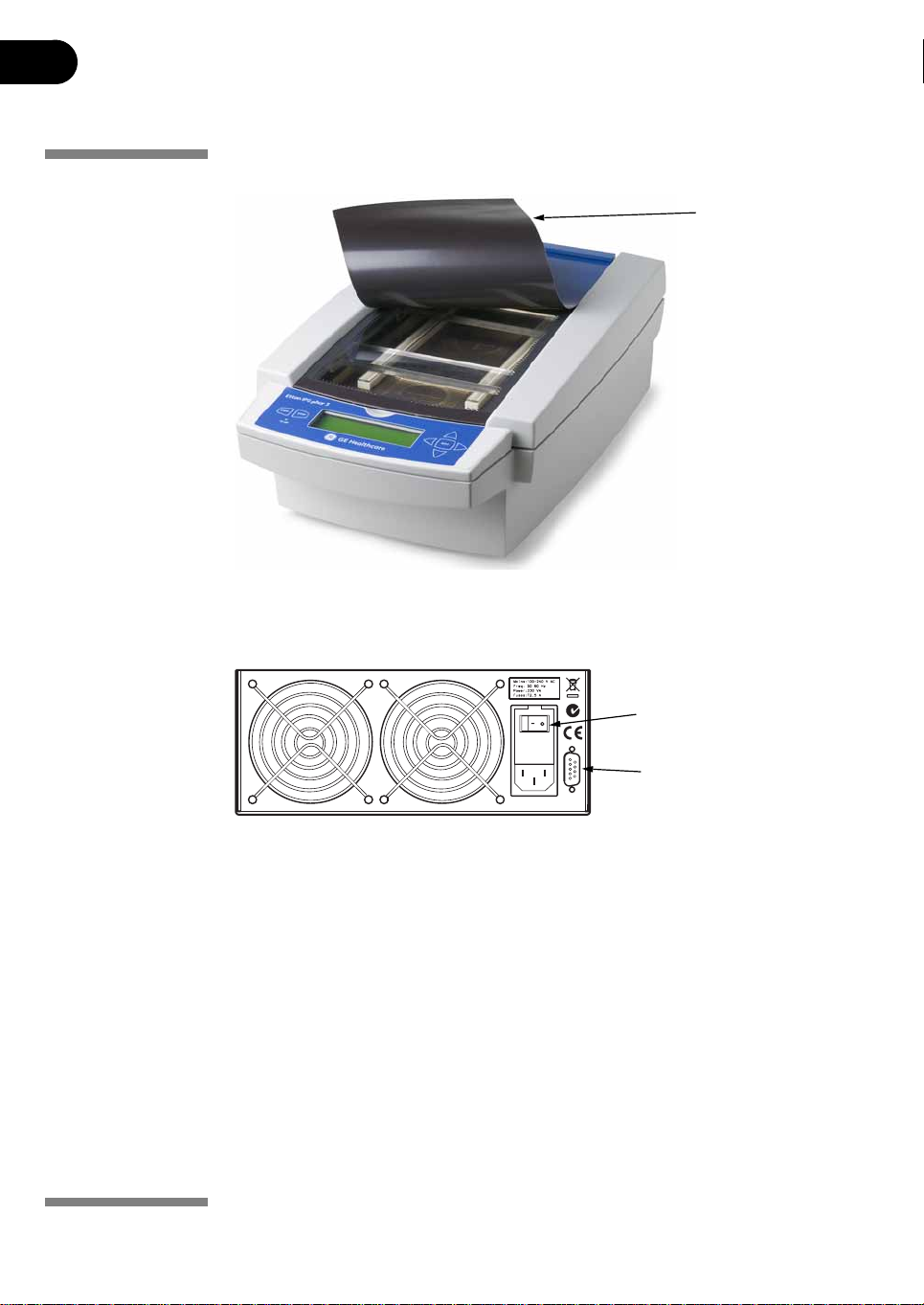
Safety lid
Fig 1-1. The Ettan IPGphor 3 instrument.
Positive (anode)
electrode area
Negative (cathode)
electrode area
Control panel
Ettan IPGphor 3 Instrument User Manual 11-0034-58 Edition AB 9
Page 10
1 Ettan IPGphor 3 Isoelectric Focusing System function and description
Fig 1-2. Light protective cover.
Light protective
cover
/
L
Fig 1-3. Location of mains power switch and serial port.
The mains power
switch is located on the
rear panel.
Serial port (RS232) for
connection to a PC
10 Ettan IPGphor 3 Instrument User Manual 11-0034-58 Edition AB
Page 11
A.
Ettan IPGphor 3 Isoelectric Focusing System function and description 1
B.
D.
G
C.
F
I.
E
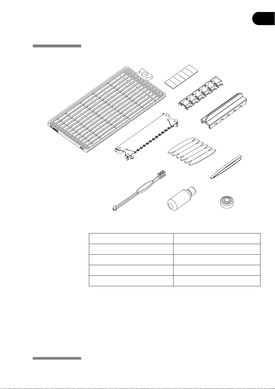
Fig 1-4. Components of the Ettan IPGphor Cup Loading Manifold system. Only one of each
item shown.
A. Manifold, ceramic or light F. Pre-cut paper bridges
B. Pre-cut electrode wicks G. Sample cup insertion tool
C. Electrode assembly H. Cleaning solution
D. Sample cups I. Forceps
E. Cleaning brush J. Spirit level
H.
J
Ettan IPGphor 3 Instrument User Manual 11-0034-58 Edition AB 11
Page 12
1 Ettan IPGphor 3 Isoelectric Focusing System function and description
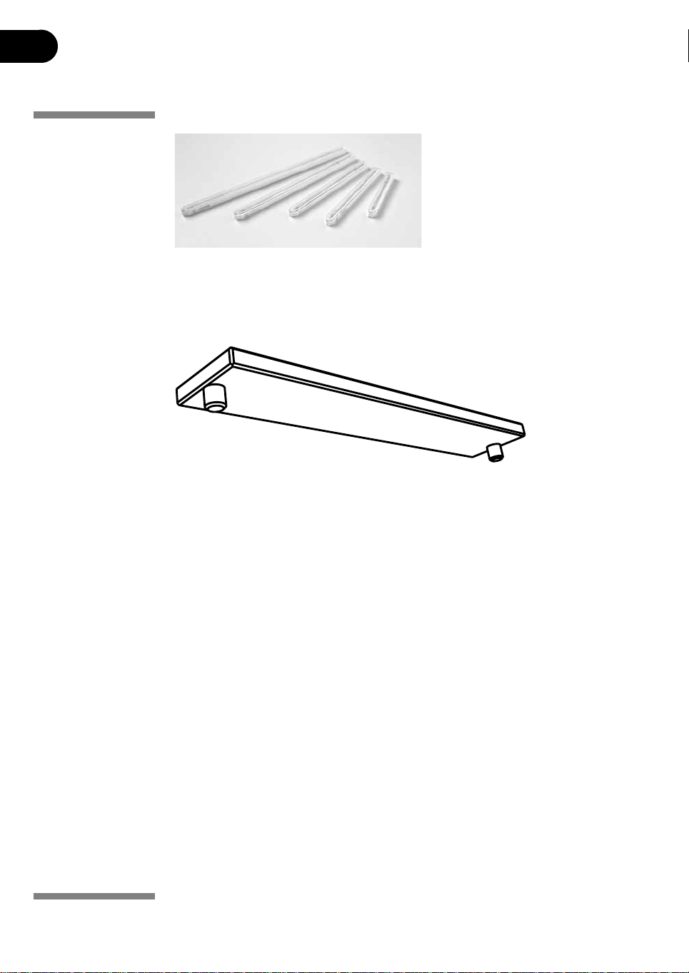
Five strip holder lengths are
available—7, 11, 13, 18, and 24 cm—
one for each IPG strip length.
Fig 1-5. Strip holders.
Note: All strips (and holders) used at any one time must be of the same length.
Fig 1-6. Lid adapter.
12 Ettan IPGphor 3 Instrument User Manual 11-0034-58 Edition AB
Page 13

Ettan IPGphor 3 Isoelectric Focusing System function and description 1
Control panel The Ettan IPGphor 3 is controlled by a 7-key membrane keypad. Instrument
status is indicated on the LCD screen.
LCD screen The
always under the protocol number “1.”
Select any protocol by pressing the
number of the desired protocol. Once the selected protocol is started, the LCD
screen indicates the parameters of the step currently being carried out.
In “edit mode” the LCD displays the programmable parameters. Position the
cursor in the field to be edited using the
value by pressing the
COMMAND keys
•The EDIT key switches the display to "edit mode", in which protocol steps
•The left arrow key moves the cursor to the left. Moving the cursor off the
•The right arrow key moves the cursor to the rig ht. Moving the cursor off
•The up arrow key increases the value of the selected field or digit, and the
•The START key begins the selected protocol.
•The STOP key pauses the protocol. Pressing the STOP key a second time
main screen is “Protocol #1, Name.” The default location of the cursor is
up and down arrow keys to display the
right and left arrow keys and adjust the
up and down arrow keys.
can be programmed (see section 3.5). Pressing the EDIT key in edit mode
toggles between the identification screen with general settings for all
steps and the settings in the three first protocol steps. The key also allows
the estimated run time r e ma ini ng to be vi ew ed w h ile the unit i s op era tin g.
screen to the left repositions the cursor at the left side of the next row. On
the bottom row the cursor is repositioned on the left side of the top row.
the screen to the right repositions the cursor at the left of the next row. On
the bottom row the cursor is repositioned on the left side of the top row.
down arrow key decreases the value of the selected field or digit.
Exceptions when the cursor is positioned to the left under the Step
number S1-S9, down arrow change the display to the next group of three
protocol steps. Up arrow change to the previous group of three protocol
steps. During electrophoresis, the up/down arrow keys are used to toggle
between VhS, VhT, and Hrs.
cancels the protocol in progress.
HV ON indicator lamp The HV ON lamp indicates that the high voltage power supply is on and
isoelectric focusing is in progress. This lamp is not illuminated during the
rehydration phase of a protocol.
Serial port RS 232 Serial port for connection of a PC.
Ettan IPGphor 3 Instrument User Manual 11-0034-58 Edition AB 13
Page 14

1 Ettan IPGphor 3 Isoelectric Focusing System function and description
Platform The platform accommodates one manifold for the first dimension isoelectric
focusing (IEF) run.
Up to 12 fixed-length strip holders can be placed on the platform for rehydration
and IEF.
The embedded electrode areas provide the electrical connection between strip
holder or manifold electrodes and the integral power supply.
Platform temperature is controlled by Peltier thermoelectric modules.
Electrode areas Both electrode areas are gold-plated copper. Placing a manifold or a strip holder
so that it bridges both electrode areas completes the electrical circuit (once the
safety lid is in position).
Safety lid The safety lid must be properly closed before power is applied.
Light protective cover When analyzing proteins labeled with light sensitive stains like CyDye®, a light
protective cover (Fig 1-2) is used. The cover is applied by magnetic force but is
easy to partially remove for checking the isoelectric focusing procedure,
especially the migration of bromo-phenol-blue at start.
Lid adapter for strip
holders
Ettan IPGphor 3
Control Software
Manifolds
Ettan IPGphor Cup
Loading Manifold
Ceramic
When using the Ettan IPGphor 3 standard strip holders a lid adapter (Fig 1-6) must
be used to apply the correct amount of pressure to the lids of the Ettan IPGphor 3
strip holders.
Ettan IPGphor 3 Control Software allows the user to control the Ettan IPGphor 3
Isoelectric Focusing Instrument. The software provides an enhanced functionality
in the areas of data presentation, data storage, and protocol handling. The PC is
connected to the Ettan IPGphor 3 over a serial cable or USB converter.
Ettan IPGphor 3 Control Software controls up to four Ettan IPGphor 3 units at one
time, each running a different set of run parameters.
The manifold (Fig 1-4) is made of aluminum oxide ceramic for efficient heat
transfer and temperature control during IEF. The manifold accomodates up to 12
IPG strips from 7 cm to 24 cm long. Immobiline DryStrip is placed with the gel side
facing up.
Samples are applied in a cup. Cup loading has been found to improve protein
focusing patterns, particularly on basic IPG strips (pH 6-9 and 6-11). Larger
sample volumes can be applied by gel rehydration loading or anodic paper
bridge loading.
Protrusions along the channel inside the manifold align the rehydrated IPG strip,
keeping it straight and centered when placed inside the manifold. The manifold
has a coating to minimize protein adsorption. The unit may also be used for IPG
strip equilibration prior to second dimension electrophoresis.
The manifold is fragile and should be handled with care.
14 Ettan IPGphor 3 Instrument User Manual 11-0034-58 Edition AB
Page 15
Ettan IPGphor 3 Isoelectric Focusing System function and description 1
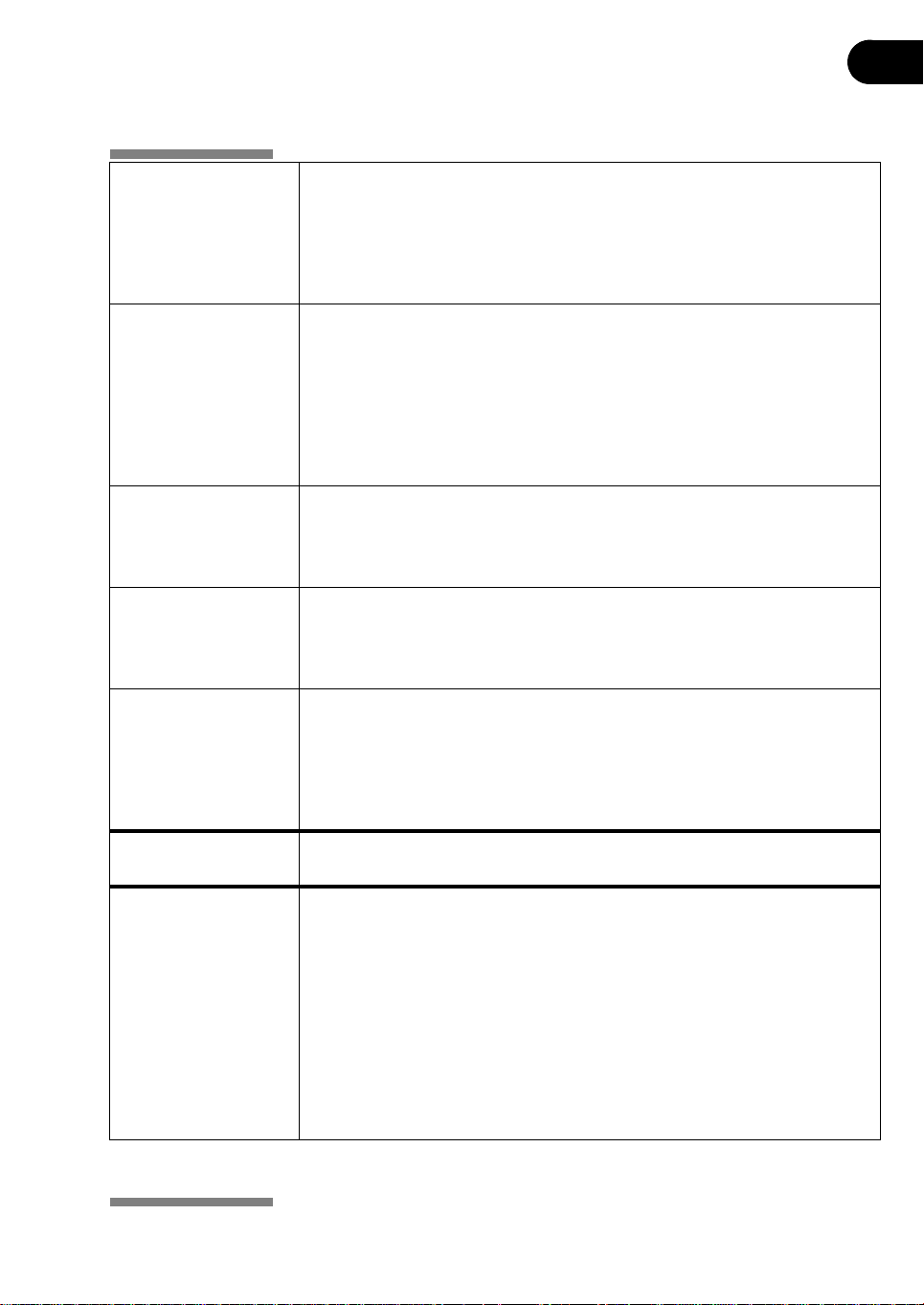
Ettan IPGphor Cup
Loading Manifold Light
Electrode Assembly These electrodes fit to both the ceramic and light manifold. The movable
Sample Cups Sample cups (Fig 1-4) can be placed along the length of the Ettan IPGphor
IEF electrode paper
wicks
Paper bridge loading
pads
The manifold (Fig 1-4) is made of polymers polycarbonate and ABS (acrylonitrilebutadiene-styrene). The light manifold and the ceramic manifold have the same
design/measurements with only the choice of materials the only difference. The
manifold accommodates up to 12 IPG strips from 7 cm to 24 cm long.
The unit may also be used for IPG strip equilibration prior to second dimension
electrophoresis.
electrodes (Fig 1-4) can be placed along the manifold to fit from 7 to 24 cm long
IPG strips.
Electrode pins make contact with the power supply electrode areas on the
platform of the Ettan IPGphor 3. The electrodes have a platinum wire that is strung
across the bottom of the electrode teeth to provide electrical contact to the IPG
strips. The hold down teeth for paper bridge loading are found along the opposite
length of the electrode. Cams on the sides of the electrode secure the position.
Manifold that is not blocked by a centering protrusion.
The sample cups are supplied in strips of 6 for easy handling and placement.
Each sample cup accommodates sample volumes of up to 150 µl.
The small, precut rectangular wicks (Fig 1-4) must be placed at both the anodal
and cathodal ends of the rehydrated IPG strips just under the electrodes.
The wicks absorb excess water, salts, and proteins with pI values that lie outside
the pH range of the IPG strip.
Paper Bridge loading pads (Fig 1-4) are used to load larger volumes of sample
(375-500 µl). The bridges are 0.8 cm
One end of the pad is in contact with the IPG strip and is held in position by the
hold down teeth of the electrode assembly. The other end of the bridge loading
pad makes contact with a paper wick placed under the platinum wire of the
electrode assembly.
× 5.0 cm in size including the pointed ends.
Immobiline DryStrip
Reswelling Tray
Strip holders The strip holders are made of aluminum oxide ceramic with electrodes of
Ettan IPGphor 3 Instrument User Manual 11-0034-58 Edition AB 15
When using the manifold the Immobiline DryStrip Reswelling Tray is required for
proper strip rehydration. The longer Tray fits 7-24 cm strip lengths.
platinum on titanium. The ceramic is very brittle so the holders are fragile and
must be handled with care.
The ceramic is treated with a special coating to minimize protein binding and
must be cleaned only with the Ettan IPGphor Cleaning Solution supplied to retain
that coating.
Strip holders are available for the following IPG strip lengths: 7, 11, 13, 18, and
24 cm.
Each fixed-length strip holder base holds a single IPG strip throughout
rehydration and isoelectric focusing. A matching length holder is available for
each size strip.
Page 16
1 Ettan IPGphor 3 Isoelectric Focusing System function and description
Sample application
wells
Cover The cover is made of acrylic and protects the IPG strip during rehydration. The
Each of the two wells accepts up to 15 µl of sample (7.5 µl on either side of the
strip) in excess of the rehydration volume (i.e. 30 µl maximum for both wells).
Introduce the sample through the wells if it is not included in the rehydration
solution.
shape of the underside of the cover ensures electrical continuity during IEF by
pressing the strip against the electrode while allowing electrolysis gases to
escape.
Rehydration and separation progress can be monitored visually through the clear
cover.
16 Ettan IPGphor 3 Instrument User Manual 11-0034-58 Edition AB
Page 17
Ettan IPGphor 3 Isoelectric Focusing System function and description 1
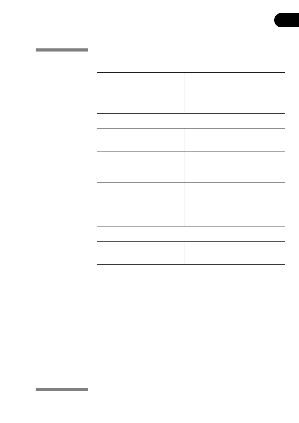
1.3 Specifications
Working surface
Electrode areas Gold-plated copper
Capacity Up to 12 fixed-length strip holders or one
manifold
Platform temperature 15–30 °C ±2 °C
User interface
Control panel 7-key membrane keypad.
Liquid crystal display (LCD) 4 lines, 24 characters per line
Programmable parameters Rehydration time, platform temperature,
maximum current limit per strip, voltage
limit in each step, voltage step or
gradient, and step duration.
Protocol capacity 10 protocols, with up to 9 steps each
Serial port RS232, 1200 or 9600 baud, 8 data bits 1
stop bit, no parity, no flow control.
9600 baud is mandatory for connection
with Ettan IPGphor 3 Control Software.
Operating environment
Temperature 15–32 °C
Relative humidity 0–70%*
* High relative humidity may result in condensation forming on the platform sur-
face. Runs conducted at a platform temperature of 20 °C and relative humidity
less than 70% will generally not cause condensation. Platform temperatures
greater than 20 °C allow for higher relative humidity without condensation. Environments for which condensation occurs on the platform surface may vary. If
condensation occurs, the unit may require conditioned air to reduce temperature and relative humidity.
Ettan IPGphor 3 Instrument User Manual 11-0034-58 Edition AB 17
Page 18
1 Ettan IPGphor 3 Isoelectric Focusing System function and description
Power requirements
Mains supply voltage 100-240 V AC ±10%
Frequency 50/60 Hz
Power consumption 230 VA
Electrophoresis
High voltage Up to 10 kV
Current Up to 1.5 mA
Physical parameters
Dimensions (h
Weight 8.3 kg
Safety
Safety features Automatic voltage cutoff when safety lid
× w × d) 160 × 278 × 471 mm
is opened
Safety certifications CE
1.4 Associated documentation
•The Ettan IPGphor 3 Software User Manual contains instructions for
controlling Ettan IPGphor 3 Isoelectric Focusing Unit from a PC.
•The Ettan IPGphor Cup Loading Manifold User Manual contains instructions
for first-dimension isoelectric focusing of proteins on IPG strips.
•The Ettan IPGphor 3 Safety Handbook contains safety information.
• Instructions attached to each package of Immobiline DryStrip.
18 Ettan IPGphor 3 Instrument User Manual 11-0034-58 Edition AB
Page 19
2 Instrument set up
2.1 Placing the instrument
WARNING! The vents at the front, back, and bottom of the instrument must
not be obstructed. Air must be free to circulate for the cooling apparatus to
function properly. Minimum free space behind the rear panel should be
10 cm.
IMPORTANT! Select a place for Ettan IPGphor 3 where it is possible to access
the mains power switch on the rear panel of the instrument.
Position the instrument on a flat surface with the spirit level in the ce nter. Turn the
leveling feet as necessary to make the instrument level and stable.
2.2 Power connection
Two power cords are supplied: one cord has a “North American” style (UL817)
3-pronged plug for 115 V~ power outlets, and the other has a “Central European”
style (CEE7/VII) plug for 230 V~ power outlets.
Instrument set up 2
1 Select the cord with the appropriate plug for the power outlet in your
laboratory. If neither of these cords are suitable for your power outlets,
obtain a detachable cord with an IEC/320/C13 (CEE22/V) outlet.
2 Plug the connectors into the power cord receptacle on the rear panel and
into a properly grounded power outlet.
Ettan IPGphor 3 Instrument User Manual 11-0034-58 Edition AB 19
Page 20

2 Instrument set up
2.3 Serial port connector for a computer connection
The RS232 serial port for a computer connection is at the rear of the unit. The type
of cable required (shielded straight serial or shielded null modem) depends on the
type of device (DTE or DCE) that it is connected to:
• If the computer is configured to re ce ive d ata o n pin 2 and transmit on pin 3,
a regular straight serial cable is required.
• For any other configuration, a null modem cable is required.
Pin number assignments and device set up details follow:
Ettan IPGphor 3 RS232 signal and pin number assignments:
Pin 2 Transmit
Pin 3 Receive
Pin 5 Ground
Other pins Not connected
The Ettan IPGphor 3 requires these settings in the device receiving data:
Baud rate 9600
Data bits 8
Stop bit 1
Start bit 1
Parity None
Flow control None
To set the baud rate:
1Press the Up and Down arrows together to access the Baud menu.
2Use the Up or Down arrows to set the baud rate.
3Use the Right arrow to exit to the main menu.
Serial Port Setup
Baud Rate: 9600
Set Up or Dn Exit>
20 Ettan IPGphor 3 Instrument User Manual 11-0034-58 Edition AB
Page 21
3 Operating instructions
The following sections will guide you through each stage of the isoelectric
focusing process using the Ettan IPGphor 3.
3.1 Power up
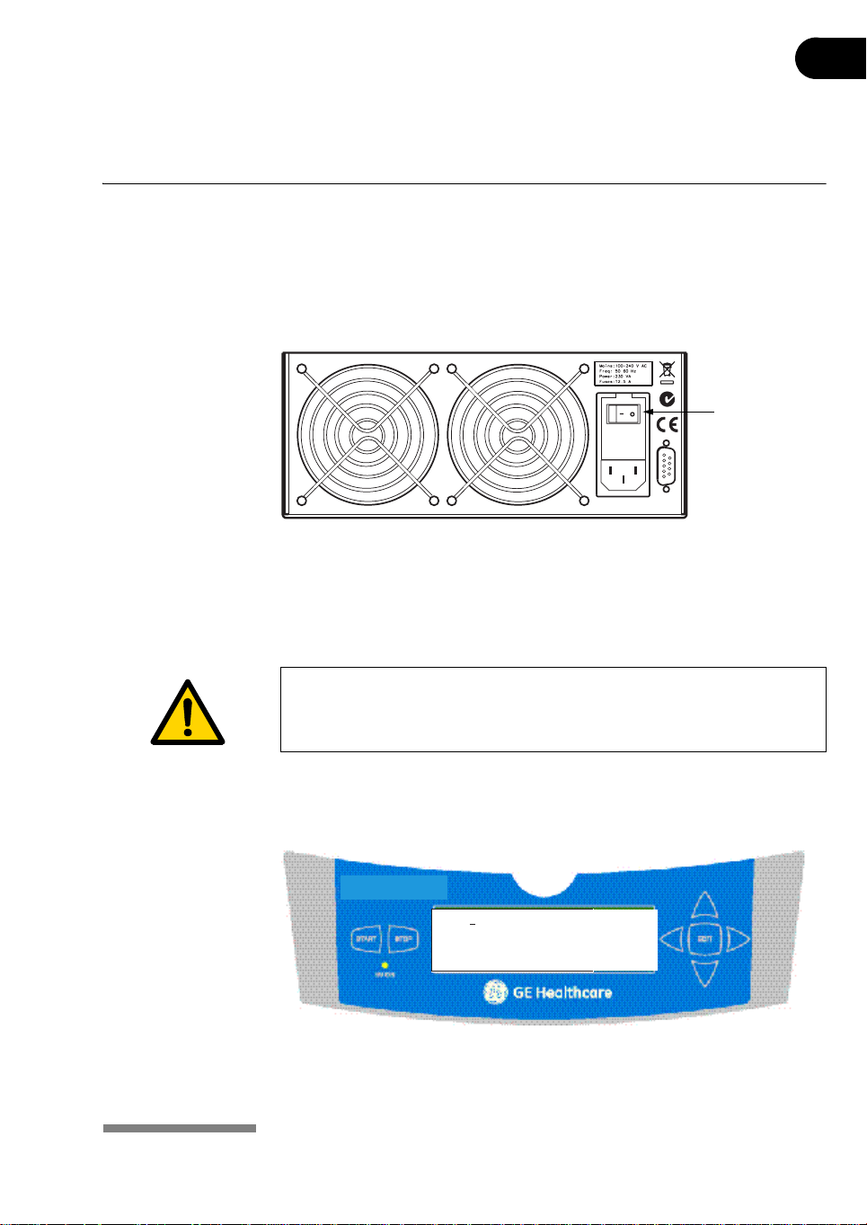
1Turn on the mains power switch (|) located on the rear panel.
This activates a self diagnostic program that runs for approximately 10
seconds. A series of screens indicate progress. If any component fails, the
diagnostic program will stop and a message will indicate the source of the
fault; note the fault and press the START key to skip to the next test. If any
failure is detected, call GE Healthcare service.
Operating instructions 3
/
L
Mains power
switch
WARNING! In a situation where there is a risk of injury, turn off the instrum ent
by switching the mains power switch (located on the rear panel) to position 0.
Malfunctions must be rectified before the Ettan IPGphor 3 is restarted.
3.1.1 Ettan IPGphor 3 control panel
Once the diagnostic program is successfully completed, the main screen
indicates that the instrument is ready, as shown below.
Ettan IPGphor 3
Prot# 1 File 1
Rehydrate 0:00Hr @ 20˚ C
IEF @ 20˚ C 50µ A/Strip
1 Strips 0 Steps
Fig 3-1. Ettan IPGphor 3 control panel.
Ettan IPGphor 3 Instrument User Manual 11-0034-58 Edition AB 21
Page 22

3 Operating instructions
•The main screen is “Protocol #1, Name.” The d efault loca tion of th e cursor is
•The START key begins the selected protocol.
•The STOP key pauses the protocol. Pressing the STOP key a second time
•The EDIT key switches the display to “edit mode”, in which protocol steps
•The up arrow key increases the value of the selected field or digit, and the
always under the protocol number “1.” Select any protocol by pressing the
up and down arrow keys to display the number of the desired protocol.
cancels the protocol in progress, and pressing it a third time resets the
instrument to start another protocol.
can be programmed. Pressing the EDIT key in edit mode toggles between
the identification with general settings for all steps and the settings in t he
three first protocol steps.
The EDIT key also allows the estimated run time remaining to be viewed
while the unit is operating.
down arrow key decreases the value of the selected field or digit.
Exceptions when the cursor is positioned to the left under the Step number
S1-S9, down arrow change the display to the next group of three protocol
steps. Up arrow change to the previous group of three protocol steps.
During electrophoresis, the up/down arrow keys are used to toggle between
VhS, VhT, and Hrs.
•The left arrow key moves the cursor to the left. Moving the cursor off the
screen to the left wraps the cursor either to the left end of the next line or to
the left end of the top row.
•The right arrow key moves the cursor to the right. Moving the cursor off the
screen to the right repositions the cursor at the left of the next row or wraps
the cursor to the left end of the top row.
22 Ettan IPGphor 3 Instrument User Manual 11-0034-58 Edition AB
Page 23
Operating instructions 3
3.2 Using the Ettan IPGphor Cup Loading Manifold
For more detailed inform a t i on, refer to Ettan IPGphor Cup Loading Manifold User
Manual.
WARNING! Check that the high voltage is turned off before op ening the safet y
lid. The HV ON indicator on the front panel should not light.
3.2.1 Rehydrating Immobiline DryStrip in the Rehydration Tray
Rehydrate the IPG strips with the gel side down in the appropriate volume of
rehydration solution, with or without sample, using the Immobiline DryStrip
Reswelling Tray.
Rehydration in the Cup Loading Manifold is not recommended, the channel is too
wide to ensure proper rehydration.
Also, follow the instructions included with the Immobiline DryStrips. Cover the IPG
strips with Immobiline DryStrip Cover Fluid, and allow the strips to rehydrate
overnight (10-20 hours).
3.2.2 Positioning the manifold on the Ettan IPGphor 3
1 Clean and dry the Ettan IPGphor 3 platform before placing the manifold on
the unit.
2 Position the manifold on the Ettan IPGphor 3 platform. The small T-shaped
protrusion fits into a cutout section of th e Ettan IP Gphor 3 pl atform nea r the
lid hinge.
3 Ensure that the manifold is level by placing the round spirit level on the
center of the manifold tray after it is placed on the Ettan IPGphor 3 unit.
4 Measure out 108 ml of Immobiline DryStrip Cover Fluid (even if fewer than 12
strips will be loaded into the manifold). Add the cover fluid evenly in the 12
manifold channels.
3.2.3 Positioning the IPG strips in the manifold
1 Transfer the strips to the Ettan IPGphor Cup Loading Manifold. 2 Position the strips under the cover fluid face up in the tray with the anodic
(+, pointed) end of the IPG strip pointing at the anode of the Ettan IPGphor 3.
3 Center the strip down the length of the manifold channel. Protrusions along
the sides guide the strip approximately straight, although some ma nual
adjustment of the strip may be necessary. See also the Ettan IPGphor Cup
Loading Manifold User Manual.
Ettan IPGphor 3 Instrument User Manual 11-0034-58 Edition AB 23
Page 24

3 Operating instructions
3.2.4 Sample cups
1 Position a strip of sample cups in the appropriate position, for example ~1 cm
2 Ensure that the feet of the cups are properly seated at the bottom of the
3 Fill the cups with cover fluid to test for proper seating of the cups. 4 Remove the cover fluid after 10 minutes.
3.2.5 Electrode paper wicks
1 Add 150 µl distilled water to each paper wick. 2 Position the wicks on each end of the IPG strips so that one end of the wick
3.2.6 Positioning the electrodes
1 With the electrode cams in the open position, position the electrode
from the end of the gel portion of the IPG strip. Do NOT place the cup with the
feet over a center protrusion.
channel. Use the insertion too l, wiggl e the tool gently w hile push ing it dow n.
overlaps the end of the gel on the IPG strip.
assembly on top of all the wicks. The electrode must be in contact with the
wick.
2 Swivel the cams into the close d position under the e xternal lip of the tray. The
electrodes should not be moved while the cams are in the closed position.
3.2.7 Loading samples into the sample cups.
1 A maximum of 150 µl of sample may be placed in these cups. 2 Check to make sure that there is cover fluid over the samples. When the
sample is introduced into the cups, it wil l sink through th e oil to the bo ttom of
the cup and come into contact with the IPG strip.
3 Close the Ettan IPGphor 3 lid. 4 Start the Ettan IPGphor 3 from the Ettan IPGph o r 3 Con tro l So ftware. See
section 3.4 for more details,
or
Program and run the Ettan IPGphor 3 from its own control panel display. See
section 3.5.
24 Ettan IPGphor 3 Instrument User Manual 11-0034-58 Edition AB
Page 25
Operating instructions 3
3.3 Using fixed-length Ettan IPGphor 3 strip holders
WARNING! Check that the high voltage is turned off before op ening the safet y
lid. The HV ON indicator on the front panel should not light.
Ettan IPGphor 3 fixed-length strip holders allow IPG strips to be rehydrated and
samples loaded in one step before proceeding automatically to perform the
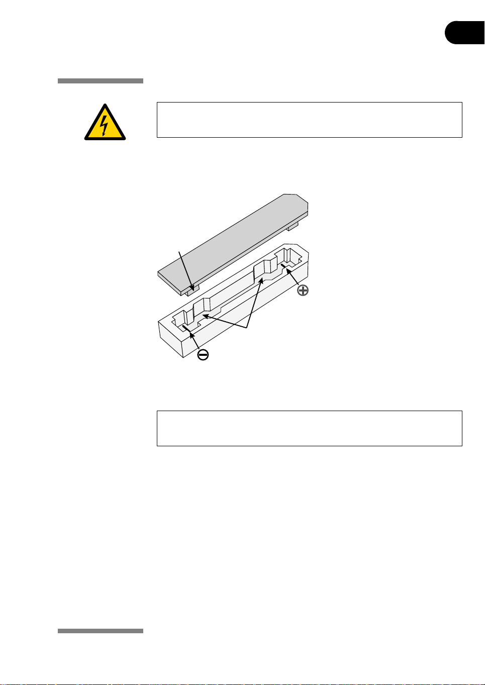
separation. The IPG strips are 3 mm wide and 0.5 mm thick after rehydration.
Cover
Pressure
block
Base
Sample
application wells
Fig 3-2. Strip holder.
3.3.1 Preparing the strip holder(s).
IMPORTANT! Handle the ceramic holders with care, as they are brittle and
fragile.
1 Select the strip holder(s) corresponding to the IPG strip length chosen for the
experiment (7, 11, 13, 18, or 24 cm).
2 Was h each holder with the str ip holder cle aning sol ution supp lied to remo ve
residual protein.
3 Rinse thoroughly with double distilled water.
4 Use a cotton swab or a lint-free tissue to dry the holder or allow it to air-dry.
The holder must be completely dry before use.
Ettan IPGphor 3 Instrument User Manual 11-0034-58 Edition AB 25
Page 26
3 Operating instructions
Rehydrate the Immobiline DryStrip
1 Prepare the rehydration solution and rehydrate the Immobiline DryStrip in
2 Follow the recommended procedures found in the Instructions attached to
Note: See also the 2-D Electrophoresis, Principles and Methods guide containing
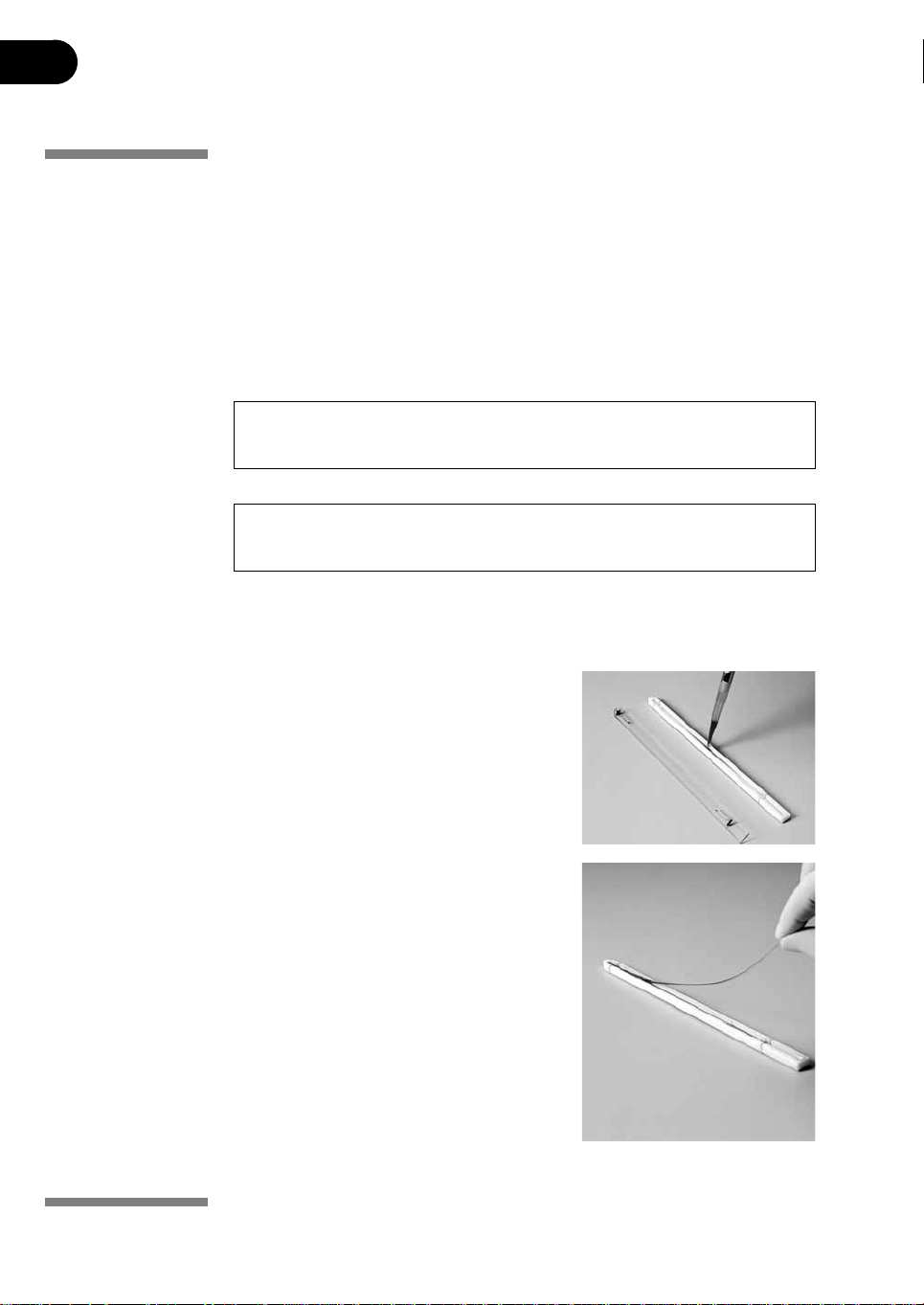
Pipet the appropriate volume of rehydration solution into each holder.
CAUTION! Always wear protective gloves when working with rehydration
solution.
IMPORTANT! To ensure complete sample uptake, do not apply excess
rehydration solution.
The correct volume to each strip length is found in the instructions attached to
each Immobiline DryStrip package.
the strip holder or in the rehydration tray when using the manifold.
each Immobiline DryStrip package.
commonly used recipes.
1 Deliver the solution slowly at a central
point in the strip holder channel away
from the sample application wells.
2 Remove any la rg er air bubbles.
Position the IPG strip
1 Remove the protective cover from the IPG
strip.
2 Position it with the gel side down and the
pointed (anodic) end of the strip directed
toward the pointed end of the strip holder.
3 Pointed end first, lower the strip onto the
solution. To help coat the entire strip,
gently lift and lower the strip and slide it
back and forth along the surface of the
solution, tilting the strip holder slightly as
needed to assure complete and even
wetting.
26 Ettan IPGphor 3 Instrument User Manual 11-0034-58 Edition AB
Page 27
Operating instructions 3
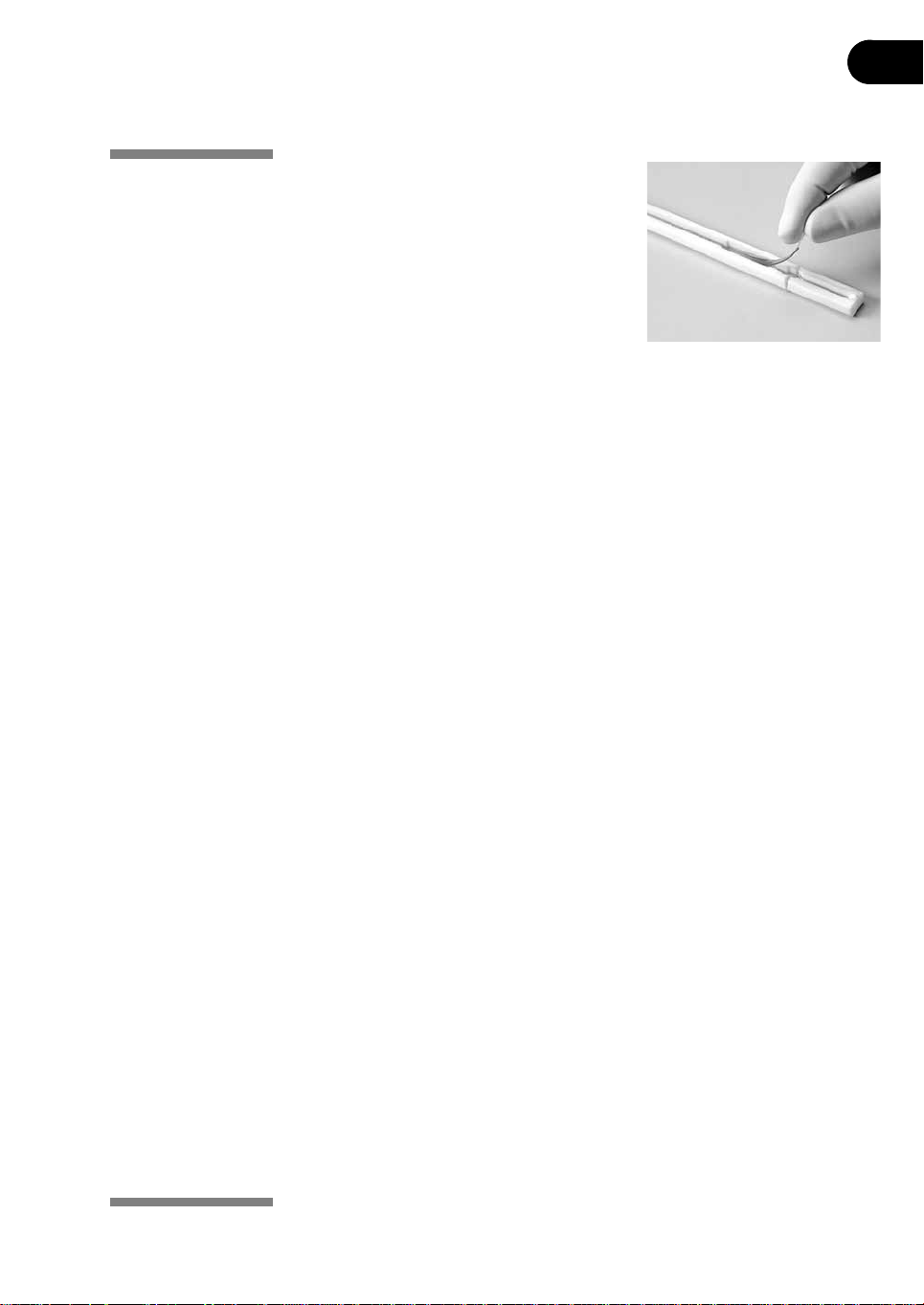
4 Final ly, l owe r the c atho dic (squa re) end of
the strip into the channel, making sure
that the IPG gel is in contact with the strip
holder electrodes at each end. The gel can
be visually identified once the rehydration
solution begins to dye the gel. Be careful
not to trap bubbles under the strip.
Applying Immobiline DryStrip Cover Fluid
Apply Immobiline DryStrip Cover Fluid to minimize evaporation and urea
crystallization.
1 Pipet the cover fluid dropwise into one end of the strip holder until one half of
the strip is covered.
2 Then pipet the cover fluid dropwise into the other end of the strip holder,
adding fluid until the entire IPG strip is covered.
Placing the cover
Position the cover on the holder. Pressure blocks on the underside of the cover
ensure that the strip maintains good contact with the electrodes as the gel
rehydrates.
Rehydration proceeding
Rehydration can proceed on the bench top or on the Ettan IPGphor 3 unit
platform. Ensure that the holder is on a level surface. A minimum of 10 h is
required for rehydration; overnight is recommended.
Alternatively, the rehydration period can be programmed as the first step of an
Ettan IPGphor 3 protocol. This is especially convenient if temperature control
during rehydration is a concern, or if a low voltage is applied during rehydration.
3.3.2 Optional: Sample rehydration under voltage
If desired, the sample can be absorbed by the IPG strip under low voltage. This
may improve the uptake of high molecular weight proteins.
To perform rehydration under voltage:
1 Set the rehydration time to 0:00 and program Step 1 of the protocol for low
voltage (30 –100 V) for 10–12 h. 2 Program additional steps as desired to achieve complete focusing.
Ettan IPGphor 3 Instrument User Manual 11-0034-58 Edition AB 27
Page 28
3 Operating instructions
3.3.3 Optional: Applying electrode pads prior to IEF
Under certain conditions, such as prolonged focusing, water may migrate toward
one end of the strip, causing the other end to begin drying out. This effect can be
minimized by placing paper electrode pads between the IPG strip and each strip
holder electrode just befor e IEF. Elect rode pads may also absorb ion s that would
otherwise accumulate at the ends of the IPG strip and possibly interfere with the
separation.
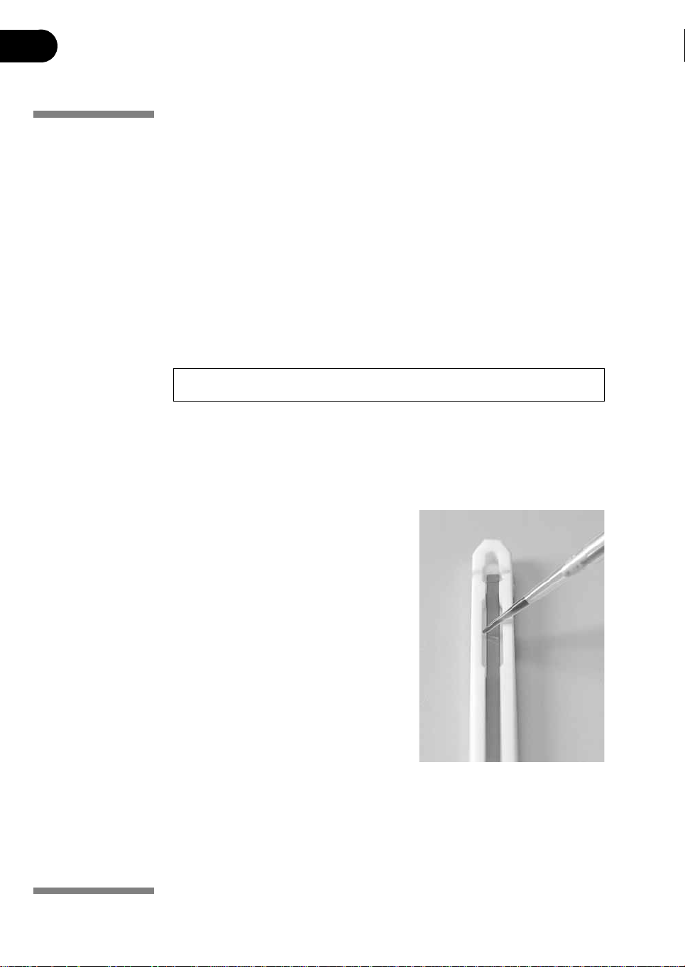
Applying electrode pads
1 Cut two 3 mm wide electrode pads from a paper IEF electrode strip
2 Position on a clean, flat surface such as a glass plate a nd soak with deionized
IMPORTANT! Electrode pads must be damp, not saturated or dripping.
3 Using forceps or tweezers, lift one end of the rehydrated IPG strip. Position an
4 Repeat at the other end.
(18-1004-40).
water. Remove excess water by blotting with tissue paper.
electrode pad over the electrode, then lower the strip back in place.
3.3.4 Optional: Applying sample after rehydration
If the sample was not applied by inclusion in
the rehydration solution, it can be applied
immediately prior to IEF.
Note: The IPG strip backing is impermeable;
do not apply the sample to the back
of the strip.
1 Prepare the sa mple in a solu tion s imila r
in composition to the rehydration
solution used.
2 Pipet the sample into either or both of
the lateral wells at either end of the strip
holder. Introduce the sample below the
cover fluid.
Up to 7.5 µl of sample solution can be added to each side (i.e. 15 µl per well or 30 µl
max. if both sides of both wells are used).
28 Ettan IPGphor 3 Instrument User Manual 11-0034-58 Edition AB
Page 29
Operating instructions 3
3.3.5 Positioning the strip holders
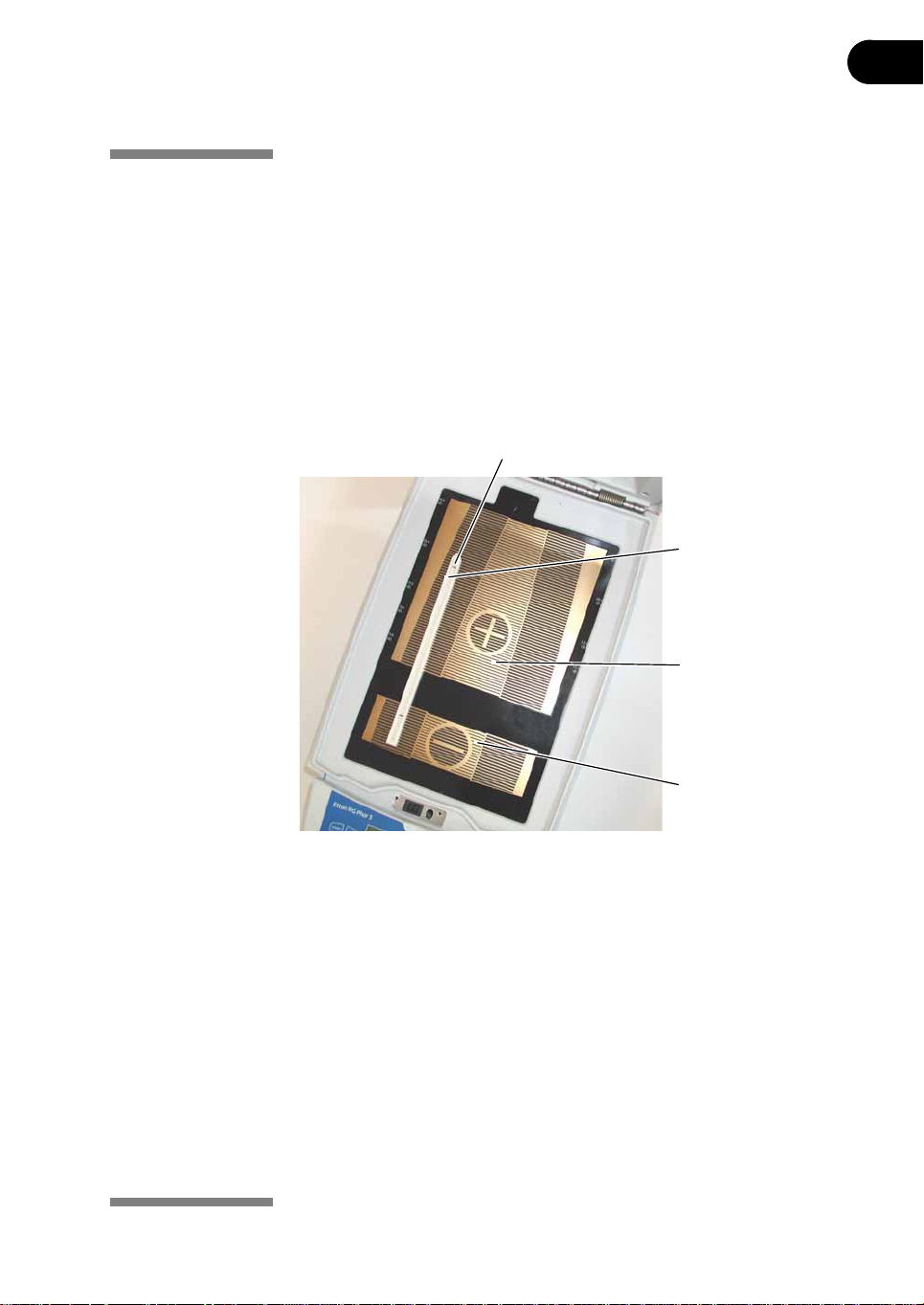
The Ettan IPGphor 3 platform has two electrode areas:
• The larger area is the positive electrode (anode)
• The smaller area is the negative electrode (cathode)
Position the strip holder on the platform as shown below: The pointed end of the
holder is over the anode (pointing to the back of the unit) and the blunt end is over
the cathode. Guidemarks along the sides of the platform show approximate
positioning for each strip holder size (7, 11, 13, 18, and 24 cm).
Electrode contacts under neath,
one in each electrode area
The pointed end of the
strip holder is in the anodic
electrode area.
Fig 3-3. Ettan IPGphor 3 electrode areas.
Anodic electrode area (+)
Cathodic electrode area (–)
Ettan IPGphor 3 Instrument User Manual 11-0034-58 Edition AB 29
Page 30
3 Operating instructions
3.3.6 Closing the safety lid
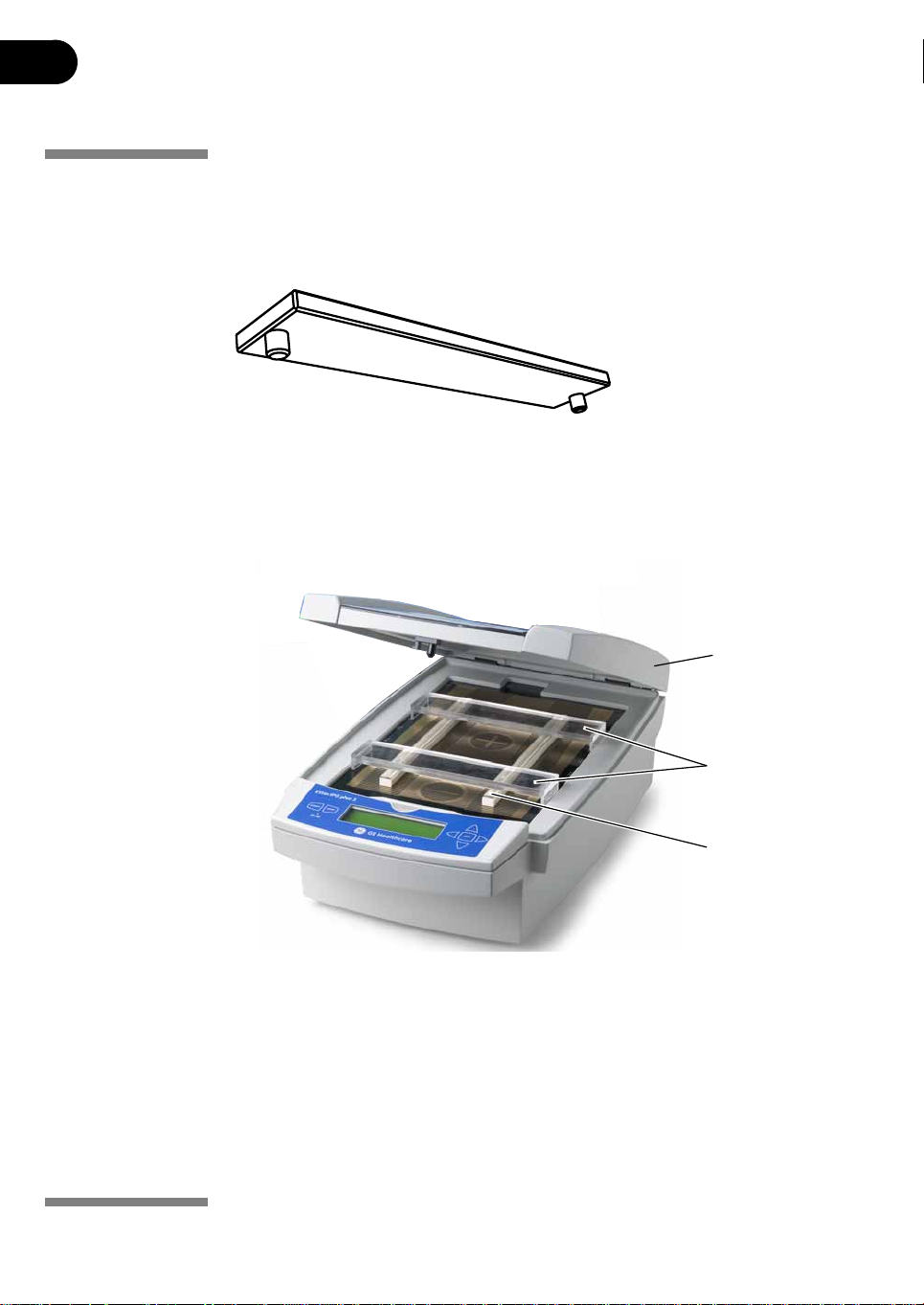
When using the IPGphor standard strip hold ers, lid adapters (see Fig 3-4) must be
used to apply the correct amount of pressure to the lids of the IPGphor strip
holders. The pressure keeps the IPG strip in contact with the IPG strip holder
electrodes.
Fig 3-4. Lid adapter.
To ensure good electrical contact when using the fixed length strip holder:
1 Apply tw o lid ad apt ers right acro ss th e lids of the strip hold ers, one over the
anodic area and the other over the ca th od ic ar ea, see Fig 3-5.
Safety lid
Lid adapters
Strip holder
with lid
Fig 3-5. Safety lid and lid adapters.
2 Use two or more strip holders and place them wide apart (see Fig 3-5) to
ensure that the lid adapters are only hanging on one strip holder and not
pressing down on the other.
3 Carefully close th e saf e ty lid by apply in g ligh t downwa rds press ure, ensu re
the mechanism locks the lid.
30 Ettan IPGphor 3 Instrument User Manual 11-0034-58 Edition AB
Page 31
Operating instructions 3
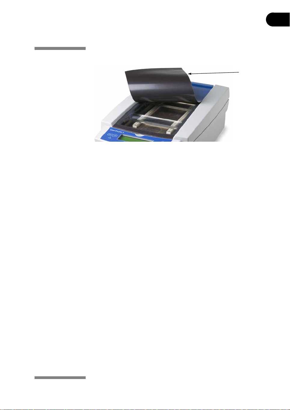
To inspect the run the light protective cover (see figure below) can be lifted
without stopping the run.
Light protective
cover
To open the safety lid:
• Press down the lid and the lock is released and th e run is st op ped. Clo se t he
lid and the run continues.
Ettan IPGphor 3 Instrument User Manual 11-0034-58 Edition AB 31
Page 32
3 Operating instructions
3.4 Running a pre-programmed protocol from the PC
WARNING! Check that the high voltage is tu rned off before opening the safety
lid. The HV ON indicator on the front panel should not light.
3.4.1 Ettan IPGphor 3 Control Software
The Ettan IPGphor 3 Control Software allows the user to control the instrument
and capture data from the serial port with a Windows® based computer and
serial cable or USB converter.
The following functions are provided:
• Selecting run protocols by choosing strip length and pH gradient
• Editing of the protocols and transferring them to the instrument
• Starting, stopping and pausing of IEF runs on the instrument:
• Acquisition of run data, which is displayed in the graph and the numerical
displays
• Event logging
• Printing and saving the display, and saving data and session log to a
Microsoft Excel spreadsheet file
For detailed instructions on installation and usage of Ettan IPGphor 3 Control
Software, and also on computer instrument connection, please refer to the Ettan
IPGphor 3 Software User Manual.
32 Ettan IPGphor 3 Instrument User Manual 11-0034-58 Edition AB
Page 33
Operating instructions 3
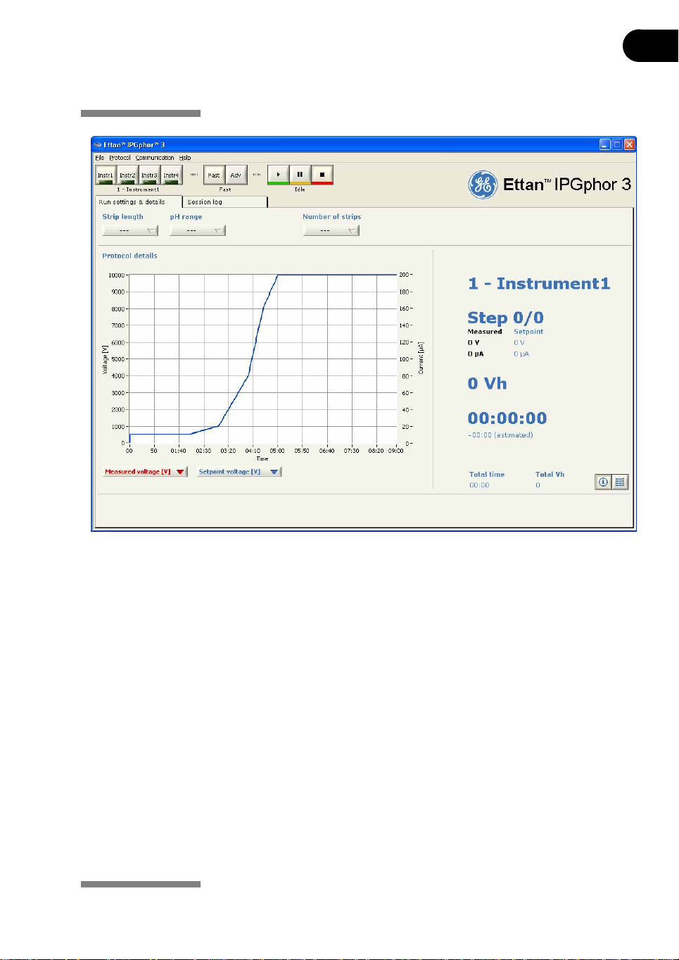
Fig 3-6. Ettan IPGphor 3 Control Software.
3.4.2 Starting the Ettan IPGphor 3 Control Software
From the Windows Start menu select Programs. Select the IPGphor program
from the menu.
Select an instrument
Select the desired Ettan IPGphor 3 instrument by clicking one of the instrument
selection buttons. The identi ty of the instrument s hould now be shown below the
buttons. Up to four instruments can be run simultaneously with the software. To
connect to an instrument:
1 Open the instrument communication settings from the menu
Communication/Instrument X.
2 Select COM port
3 Select instrument name
4Check the Active check box.
Ettan IPGphor 3 Instrument User Manual 11-0034-58 Edition AB 33
Page 34

3 Operating instructions
Protocol mode options
When setting the protocol for the run there are two main options:
• Fast mode
• Advanced mode
The selection is made by the protocol mode buttons and the selected mode is
indicated below the buttons.
In the fast mode option the software selects an optimized protocol based on the
tray type, strip length and pH range to be used. Fu rther, by switching to advanced
mode, this protocol can be edited and saved to a file.
Fast mode protocol
Select fast mode by clicking the left of the two central control buttons, labeled
with an arrow. The display beneath the buttons will now show “Fast”.
Enter experimental parameters
After selecting the fast mode protocol select the Run settings & details tab. The
strip length, pH range and number of strips should be set by using the combo
boxes at the top of the tab window. The software wil l now select the optimal
protocol for these parameters.
Edit selected protocol
Select the Protocol view in the Run settings & details tab by clicking the right of
the two buttons at the botto m right hand corn er of th e tab w indow . The prot ocol
selected by the software is now shown in detail. It is now possible to edit any
values in the protocol by clicking the writing field and entering desired changes.
Transfer the protocol to an instrument
After finishing the protocol handling as described in Ettan IPGphor 3 Software
User Manual, the desired protocol must be tr ansferred to the correct instrument
before starting a run.
Check that the desired instrument is selected. The identity of the selected
instrument is indicated bel ow the inst rument se lectio n control buttons , see Ettan
IPGphor 3 Software User Manual. Change instrument if needed by pressing the
correct instrument control button.
Select the Protocol view in the Run settings & details tab by clicking the tab and
then the right of the two buttons at the bottom right hand corner of the tab
window. Use the Protocol to instrument combo box to transfer the current
protocol to the instrument.
34 Ettan IPGphor 3 Instrument User Manual 11-0034-58 Edition AB
Page 35

Operating instructions 3
Starting a run
To start the run after transferring the protocol:
1Press the start run button (the left button of the instrument control buttons
at the top right of the application window). The run is now started and that
status is indicated by the word "Running" below the instrument control
buttons.
Monitoring a run
1 Select the desired instrument by clicking the correct instrument control
button. The identity of the selected instrument is shown below the control
buttons.
2 Select the Info and data view in the Run settings & details tab by clicking
the tab heading and then th e left of the two butt ons at the bottom rig ht hand
corner of the tab window. A number of run parameters are displayed.
3In the protocol details graph the values of two of three possible parameters
(setpoint voltage, measured voltage and measured current) can be displayed
by selecting from the combo boxes below the graph.
Ettan IPGphor 3 Control Software graphs the data (Voltage, Volt-hours and
Current) as it is retrieved from Ettan IPGphor 3 Isoelectric Focusing Unit.
The user can monitor and display the progress o f any individual run from any one
of four different instruments being run in parallel.
Stopping a run
To stop an ongoing run:
1Press the stop run button (the right button of the instrument control buttons
at top right in the application window). The run is now stopped. To indicate
that the run has stopped, “Idle” is displayed below the instrument control
buttons'.
When using the stop button it is not possible to start the protocol again except
from the beginning of the protocol.
Log file of a run
During the run important events are logged in the session log, which is shown
when the Session log tab is selected in the application window. The log file stores
instrument identity, User ID, current protocol, start time and many other
parameters, see Ettan IPGphor 3 Software User Manual for details.
Ettan IPGphor 3 Instrument User Manual 11-0034-58 Edition AB 35
Page 36

3 Operating instructions
Capturing run data
Run data is acquired from the Ettan IPGphor 3 Isoelectric Focusing Unit
automatically every minute during a run, and the data is presented in a graph
and in numerical displays.
Storing data
All run data and the session log can be exported to a Microsoft Excel f ile. It is also
possible to save the current application window as an image file. To export data:
1 Select Export from the File drop-down menu. 2 The default file name is the date and time (e.g. Apr 11, 2005 10.56.45). 3 The default location for the saved file is C:\IPGphor3\RunData.
36 Ettan IPGphor 3 Instrument User Manual 11-0034-58 Edition AB
Page 37

Operating instructions 3
3.5 Creating, editing, and running protocol programs
from the Ettan IPGphor 3 control panel
WARNING! Check that the high voltage is turned off before op ening the safet y
lid. The HV ON indicator on the front panel should not light.
3.5.1 Protocol parameters
The Ettan IPGphor 3 can store up to ten protocols. Programmable protocol
parameters include:
• duration and temperature of the rehydration phase
• duration, temperature, and power parameters for up to nine IEF st ep s fo r
each protocol
• power parameters including maximum current, voltage, and voltage
change pattern.
Please refer to the 2-D Electrophoresis, principles and methods guide for sample
handling recommendations and protocol guidelines. The permitted range of
values for each programmable parameter is listed below.
Parameter Operational range Recommended values
Steps 1–9
Step duration (hrs) rehydration: 0–99:59
focusing: 0–99:59
Volts (V) 0–10000 100–10000
Max. current 1500 µA total for 12 strips max. 50–75 µA per strip
Platform temperature (°C) rehydration: 15–30
focusing: 15–30
10:00–14:00
2:00–10:00
20
20
Navigating parameter “fields” and “digits”:
• Each screen consists of information as well as one or more fields that can be
edited. The active fields contain individually adjustable digits or characters.
• Certain digits are also linked to their neighbouring digits. For example, three
of the four digits in the voltage field can each be adjusted individually, but
when adjusting the value from 1000 to 990, for instance, even though only
the ten’s place is adjusted manua lly, three digits are affected.
• Whether individual or linked, digits “wrap around,” so increasing from 9
produces 0 and decreasing from 0 produces 9—until a parameter limit is
reached.
The Ettan IPGphor 3 can be programmed i n volt-hours (Vhr) or hours and minutes
in step-n-hold or in gradient mode. Any values within the operating limits listed
above can be used.
Ettan IPGphor 3 Instrument User Manual 11-0034-58 Edition AB 37
Page 38
3 Operating instructions
3.5.2 Editing protocol parameters
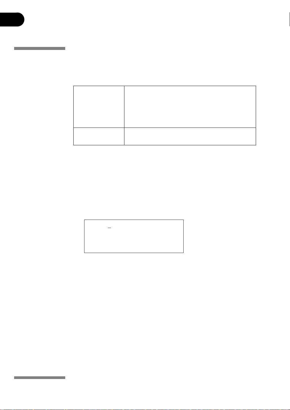
All protocol parameters are set in the edit mode. Pressing the EDIT key toggles
between the first editable screen and the protocol ide ntificatio n screen. For each
protocol, the four different screens accessible in edit mode are:
Screen 1 Protocol number and name
Screen 2–4 the nine steps available for IEF conditions (voltage change
This section covers the programming, editing, or verifying of all parameter values
Selecting protocol
Select the protocol to be created or edited from the main screen:
1 Position the cursor under the protocol number field using the right and left
Rehydration time, temperature
IEF run conditions (temperature and maximum
current/strip), number of strips and number of steps in the
selected protocol.
pattern, voltage, and step duration) in groups of 3
arrow keys.
2 Move to the desired protocol number using the up and down arrow keys.
Prot# 1 File 1
Rehydrate 0:00Hr @ 20˚ C
IEF @ 20˚ C 50µ A/Strip
1 Strips 0 Steps
3 The file name may be edited by using the right arrow to move into the file
name and up and down arrows to adjust the characters as desired. To skip
editing the name use the left arrow to proceed to the next line.
4 To change any letter, move the cursor to that location using the right and
left arrow keys and then scroll through the 37 available options using the up
and down arrow keys. Once the desired letter appears, move the cursor to
the next character to be set.
5 The original label “File #” occupies 6 of the 16 available characters. To
change the label to a more descriptive name, such as “11 CM 3–10L,”
requires scrolling through the alphanumeric op tions for each of t he 11 digits
in the name.
38 Ettan IPGphor 3 Instrument User Manual 11-0034-58 Edition AB
Page 39
Operating instructions 3
Editing protocol parameters
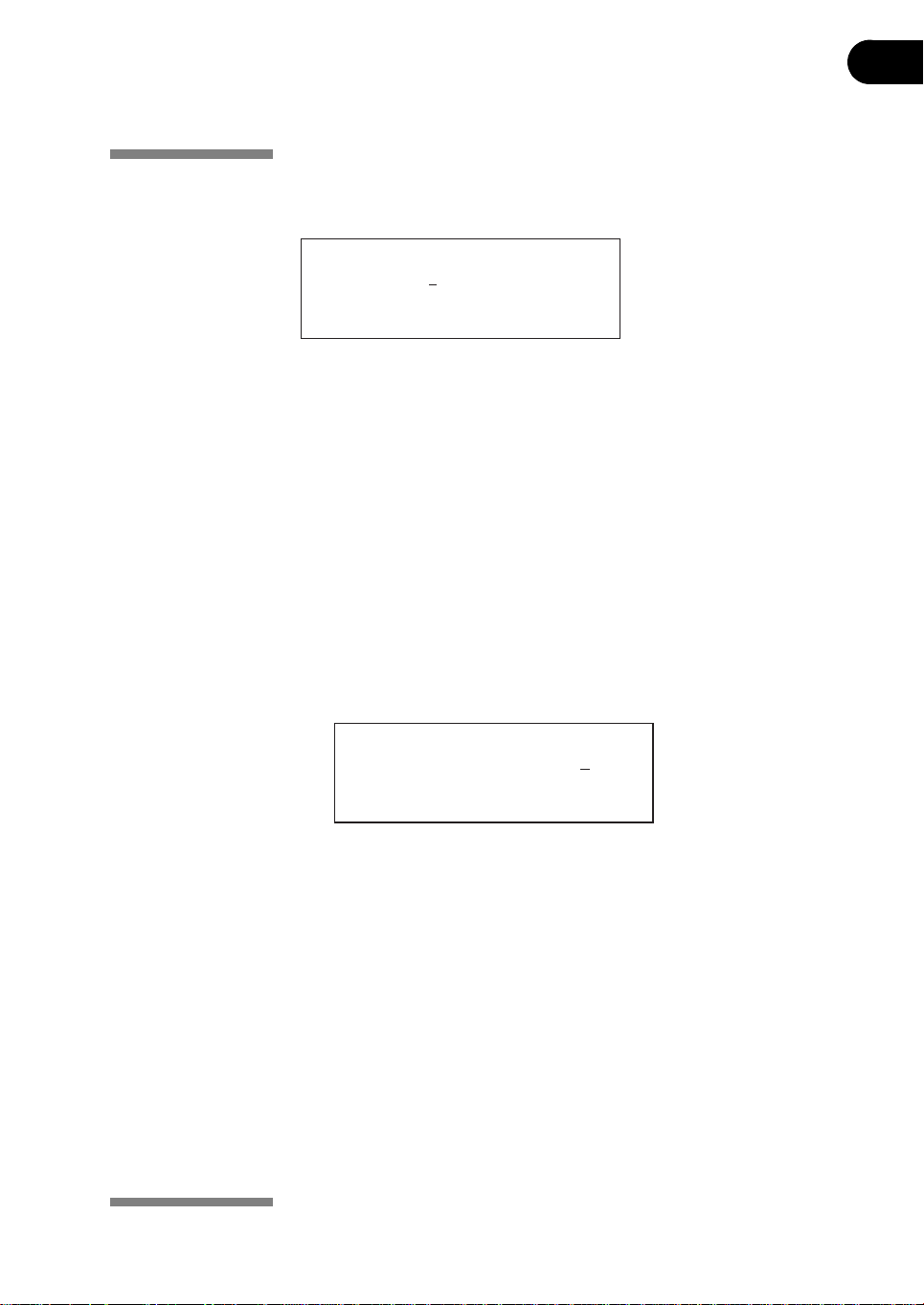
Edit the Rehydration parameters, time and temperature, an d the IEF parameters,
temperature, µA/Strip and number of strips as necessary.
Prot# 1 File 1
Rehydrate 10:00Hr @ 20˚ C
IEF @ 20˚ C 50µ A/Strip
1 Strips 0 Steps
Note: The cursor stops only in the fields that can be edited. Once the cursor is in
position, press the up or down arrow keys to adjust the value.
The available time range is 0–99:59 h, with 10 min resolution. (Hence, only the first
three digits are editable). A minimum of 10 h is required for the rehydration of IPG
strip gels, but overnight is recommended. This protocol step can also be used as
a simple timer to start the protocol at a convenient time. If the IPG strips are
already rehydrated and ready for immediate focusing, set the rehydration
duration to 00:00 Hrs.
To adjust the rehydration temperature:
1use the left and right arrow keys to position the cursor and
2the up and down arrow keys to se lect the value with in the range of 15 –30 °C.
The original factory programmed value is 20 °C.
Prot# 1 File 1
Rehydrate 10:00Hr @ 20˚ C
IEF @ 20˚ C 50µ A/Strip
1 Strips 0 Steps
Note: Maintaining the actual platform temperature at <18 °C or >25 °C may
require placement of the Ettan IPGphor 3 unit in a location of lower or
higher than ambient temperature (e.g. a cold room).
It may be necessary to operate the instrument in an air conditioned room
to prevent condensation from collecting on the platform in humid
environments when the platform is run at greater than 7 °C below ambient
temperature.
The third line contains fields to set the platform temperature and current limit for
all isoelectric focusing steps:
Ettan IPGphor 3 Instrument User Manual 11-0034-58 Edition AB 39
Page 40
3 Operating instructions
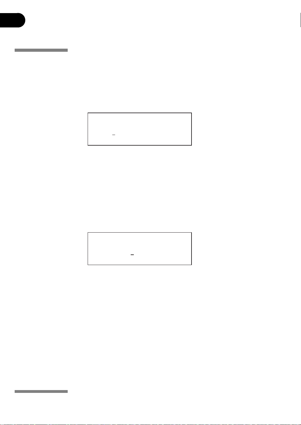
The original factory programmed IEF te mperature is 20 °C. To adjust the
temperature:
1use the left and right arrow keys to position the cursor in the active °C field,
2use the up and down arrow keys to select the value within the range of 15–
The original factory programmed value is 50 µA per IPG strip.
To adjust the current limit:
1use the left and right arrow keys to position the cursor under one of the
and
30 °C.
Prot# 1 File 1
Rehydrate 10:00Hr @ 20˚ C
IEF @ 20˚ C 50µ A/Strip
1 Strips 0 Steps
three active µA digits, and
2use the up and down arrow keys to select the value within the range
0–200 µA per strip.
Note: The total deliverable amperage is 1500 µA.
Prot# 1 File 1
Rehydrate 10:00Hr @ 20˚ C
IEF @ 20˚ C 50µ A/Strip
1 Strips 0 Steps
3 Use the arrow keys to adjust the numbers of strips to run. 4 To advance to the next edit screen, press the EDIT key.
IEF programming
The second screen in edit mode is the first in a series of nine programmable IEF
steps in which the voltage change pattern, voltage, an d step duration are set. The
steps are displayed in groups of 3 steps per screen. The number of steps which
have been programmed is displayed next to the protocol number.
Each step is identified by “S” an d the step number and can be accessed by
placing the cursor under the step number using the right and left arrow keys. To
advance to the next step group press the down arrow key and to return to a
previous step group press the up arrow key.
40 Ettan IPGphor 3 Instrument User Manual 11-0034-58 Edition AB
Page 41
Operating instructions 3
The two options for the voltage change pattern are:
• Step, which sets the voltage at the selected value for the new step and then
holds the voltage constant for the step duration; and
• Gradient, which increases the voltage limit (linearly with respect to time)
from the value set for the p revious step t o the va lue se t for th is ste p. If th is is
the first step, the value incr eases from 0.
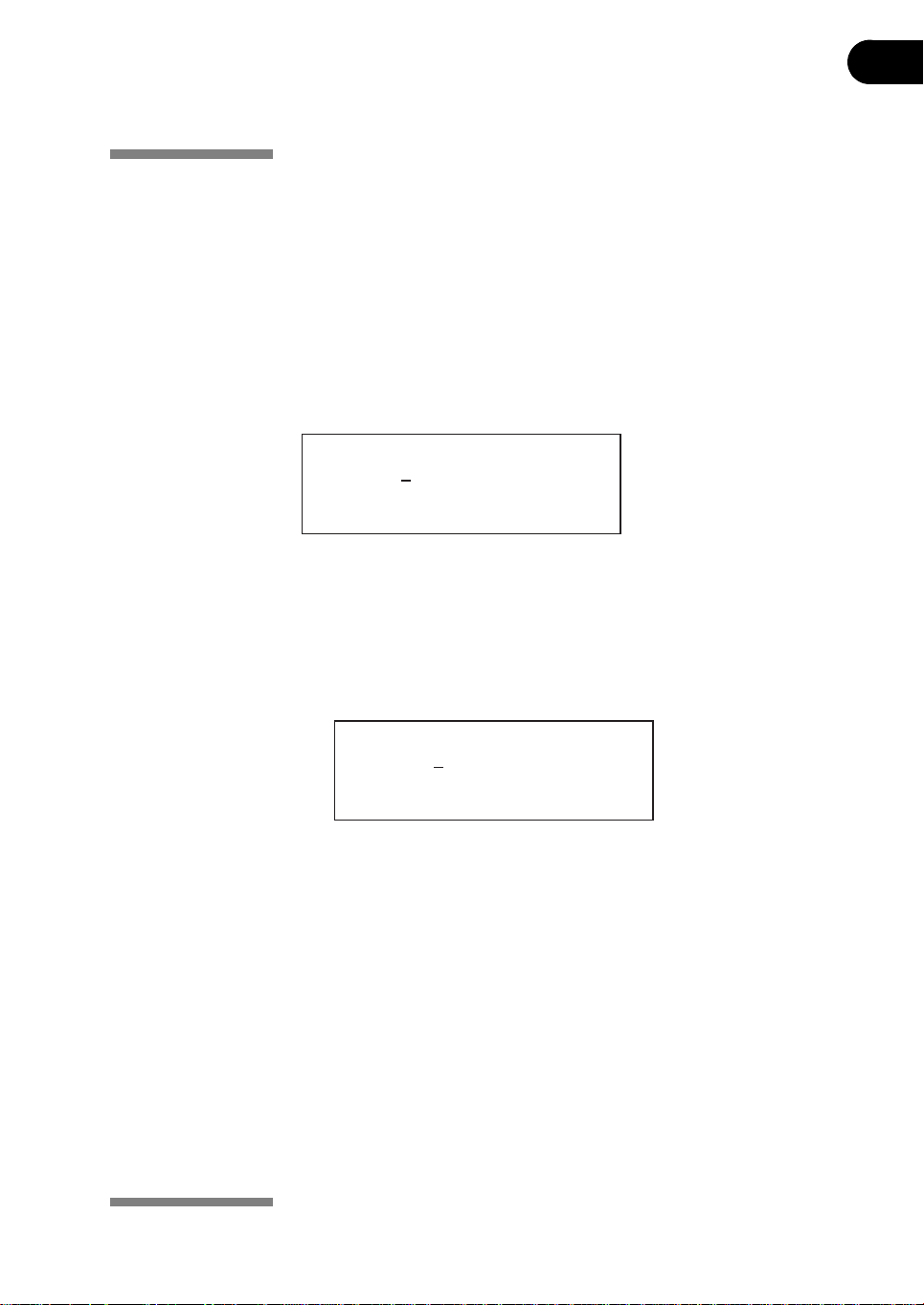
The original programmed option is Step for each step. To toggle to Gradient,
move the cursor to the Step field using the right and left arrow keys and toggle
with the up or down arrow key:
Prot# 1 3 Steps
S1 Grad 500V 1:00 Hrs
S2 Grad 1000V 4:00 Hrs
S3 Step 8000V 80000 Vhr
IEF voltage is programmable from 0 –8000 V in increments of 10 V. Each of the
first three digits in the voltage field can be set independently.
1 First move the cursor to the desired digit location using the right and left
arrow keys, and
2 then change the value using the up and down arrow keys.
Prot# 1 3 Steps
S1 Grad 500V 1:00 Hrs
S2 Grad 1000V 4:00 Hrs
S3 Step 8000V 80000 Vhr
The original factory programmed voltage for each step is 0. Program each step
with the protocol voltage values. If fewer than nine steps are required, end the
program by assigning a value of 0 V aft e r the final step. The step duration (0 to
99:59 hours) or volt-hours (0 to 300000 Vhr) are programmable for each step.
To select, set the cursor under the currently selected field and use the up or down
arrow key to toggle between Hrs and Vhrs. To set the digits:
1 first move the cursor to the desired digit location using the right and left
arrow keys, and
2 then change the value using the up and down arrow keys.
Ettan IPGphor 3 Instrument User Manual 11-0034-58 Edition AB 41
Page 42
3 Operating instructions
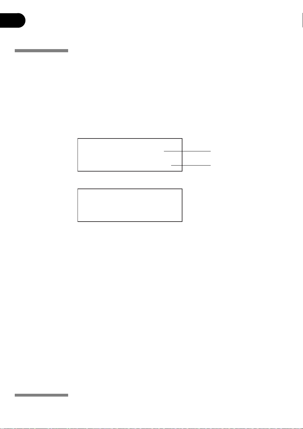
The original factory programmed time for each step is 0:00, and should be set to
0:00 for all unused steps. The Vhrs value is calculated according to the
explanatory note at the left, but these values can be set in the same manner as
the Hrs values.
Note: When toggling from Hrs to Vhr, the value in the Vhrs field is automatically
Prot# 1 3 Steps
S1 Grad 500V 1:00 Hrs
S2 Grad 1000V 4:00 Hrs
S3 Step 8000V 80000 Vhr
Prot# 1 3 Steps
S1 Grad 500V 1:00 Hrs
S2 Grad 2000V 1:00 Hrs
S3 Step 8000V 2:00 Hrs
calculated according to the selected voltage change pattern:
For Step-n-hold, Vhr is the product of hours and voltage.
For Gradient, Vhr is the product of hours and the mean of the voltage limit
set for the current step and the previous step.
Absolute Vhr limits can be set to any value from 1–30000 Vhr.
hours step
volt-hours step
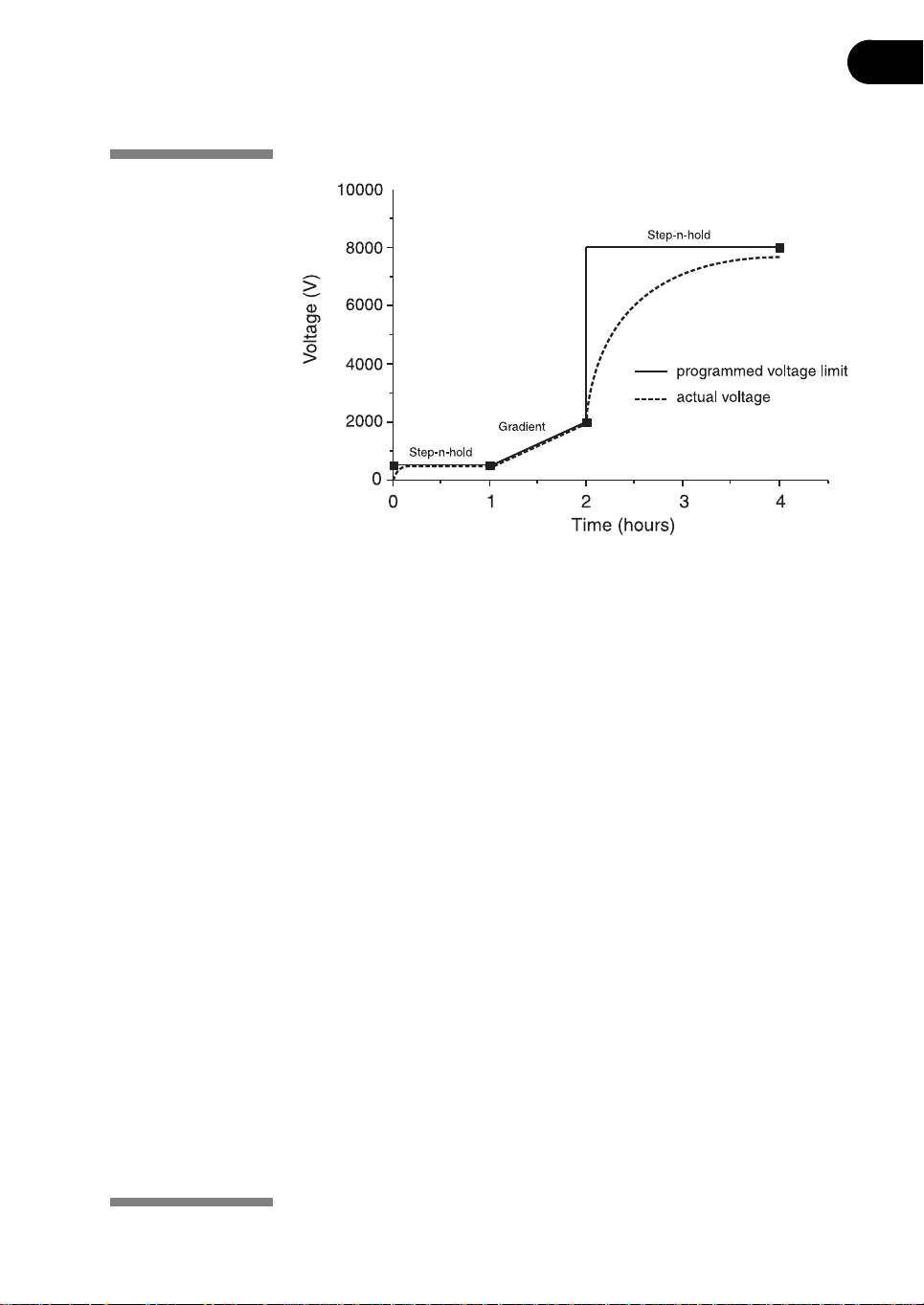
Programming example
Simplified 4-step protocol and resulting voltage profile
To illustrate the two voltage change patterns, a simplified example shows
program steps and the resulting voltage profile. Note that step 4 ends the
protocol.
For recommended IEF protocols, see the 2-D Electrophoresis Principles and
Methods guide.
42 Ettan IPGphor 3 Instrument User Manual 11-0034-58 Edition AB
Page 43
Operating instructions 3
Fig 3-7. Voltage profile.
Note: The set voltage is the voltage limit. Under conditions of limiting current, it
may take some time for the maximum voltage to be reached, and under
certain power conditions, it may not be reached at all.
A lower voltage step may be entered at the end of the Ettan IPGphor 3 protocol.
Band sharpness will decrease however.
Verifying the protocol
To verify the protocol:
1 scroll through each step: position the cursor in the step number field using
the right and left arrow keys, and
2 then advance through the steps using the up and down arrow keys. Edit as required by placing the cursor with the right and left arrow keys and
adjusting the value with the up and down arrow keys.
Make sure that the voltage field in all unused steps displays a value of 0, or that
the value in the Hrs field is 00:00.
Note: Pressing the up arrow key in screen 4 wraps back to the rehydration
screen.
Exiting edit mode
Press the EDIT key to save any changes and exit the step edit mode. The protocol
identification screen will appear.
Ettan IPGphor 3 Instrument User Manual 11-0034-58 Edition AB 43
Page 44
3 Operating instructions
3.5.3 Starting isoelectric focusing from the Ettan IPGphor 3 control
Selecting the protocol number
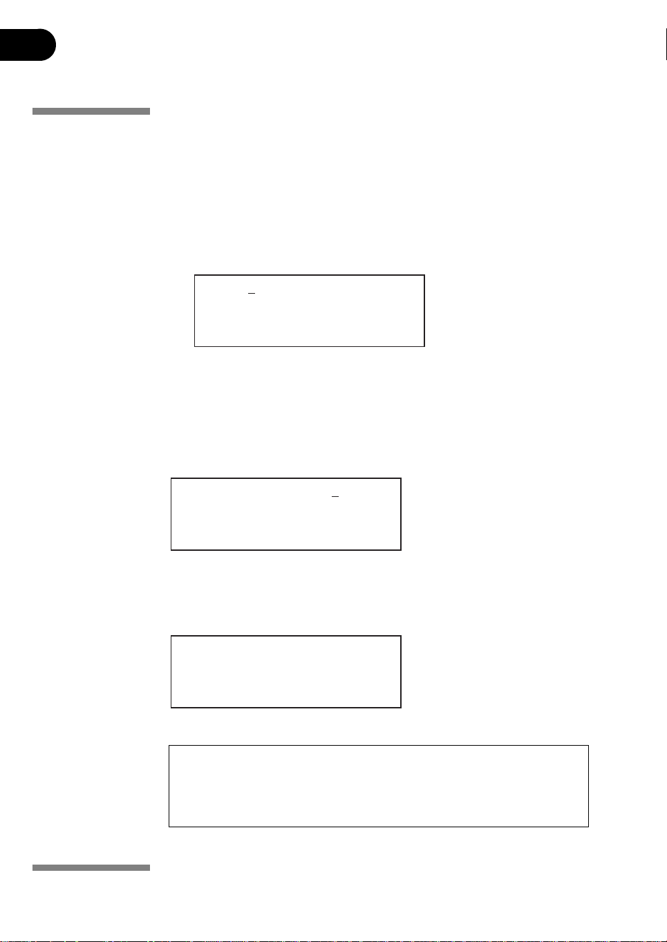
Advance to the protocol identification screen by:
1 placing the cursor in the protocol number field using the right and left arrow
2 selecting the protocol number using the up and down arrow keys.
3Use the right and left arrow keys to position the cursor to set the number of
4Press the START key.
A screen is displayed to confirm the number of strips to run. Adjust the number of
strips if necessary.
panel
keys, and
Prot# 1 MY PROTOCOL
Rehydrate 10:00Hr @ 20˚ C
IEF @ 20˚ C 200µ A/Strip
12 Strips 3 Steps
strips to run, and the up and down arrow keys to select the number (1–12)
Number of strips :12
Press START to continue
1Press START to continue.
If the safety lid is not properly closed the following message will indicate the
required action:
Lid open step 1
Close lid to continue
CAUTION! During IEF:
- do not lean on the safety lid,
- do not apply excess pressure or uneven weight to the lid, and
- do not place any items on the lid.
44 Ettan IPGphor 3 Instrument User Manual 11-0034-58 Edition AB
Page 45
Operating instructions 3
After securing the safety lid:
1Press the START key again.
Once the protocol begins, each step is carried out automatically, and instrument
status for each step is indicated on the screen.
Platform temperature and time remaining can be changed while the protocol is
in progress, and each such possibility is discussed in turn below.
The first screen will indicate the protocol, number of steps, and total hours
(excluding rehydration time):
Starting protocol # 1
3 steps 4:00 Hr
If a rehydration period was programmed, the rehydration status screen will
indicate the number of hours elapsed and the actual platform temperature:
Running Prot# 1
Rehydration for 10:00 Hr
0:01 Hr Elapsed
Rehydrate at 20˚ C
To change rehydration duration or other parameters:
1Press the EDIT key to display the set screen:
The first line indicates that the proto col is running. Pre ssing Edit again will access
the step setting screen. Pressing Edit again will return to the Running screen.
Any changes made while a protocol is running are applied to the current run only,
the stored protocol is not affected.
Running Prot# 1
Rehydrate 10:00Hr @ 20˚ C
IEF @ 20˚ C 200 µ A/Strip
12 Strips 3 Steps
Move the cursor under the digit you wish to set and change it using the up and
down arrow keys. To end this step, s et a ll digi ts to 0. This screen is automatically
replaced by the regular status screen after a few seconds.
The temperature field can be changed directly (without pressing the EDIT key):
Ettan IPGphor 3 Instrument User Manual 11-0034-58 Edition AB 45
Page 46
3 Operating instructions
1use the right and left arrow keys to position the cursor in the temperature
2use the up and down arrow keys to adjust the value.
Isoelectric focusing will begin after the rehydration step is complete. The HV ON
lamp will light and the status screen showing the step currently in progress as
well as all parameters will appear:
Running Prot# 1 @ 20˚ C
Step 1 of 3 Vhrs
Step Vhrs Elapsed
500V 40µ A/Strip 0.0W
Note: The indicated wattage is the total power delivered to all strips, and will
field, and
It may take up to 30 minutes to reach the set te mperature, depending on
ambient conditions.
often read 0 W because any value less than 0.5 is rounded down to 0. If the
delivered power exceeds 0.4 W per strip, stop the run and reduce the V or
µA settings.
The current platform temperature is indicated.
The average current per IPG strip (µA), the total instantaneous power delivered
(W), and actual voltage (V) are indicated. If the current is the limiting parameter,
the “A” in “µA” will flash.
The Ettan IPGphor 3 will display the volt-hours during the run as:
• VhS, which indicates the total volt hours for that step, or
• VhT, the total volt-hours accumulated during the entire run at the current
time.
Hours elapsed for the current step will be indicated by Hrs.
46 Ettan IPGphor 3 Instrument User Manual 11-0034-58 Edition AB
Page 47
Operating instructions 3
To toggle between VhT, VhS and Hrs:
1 mo v e th e cu r sor to the Hrs/Vhrs field of the display using the right or left
arrow key, and
2 change the display to reflect VhT, VhS and Hrs using the up and down keys.
To change the display to show remaining Hrs, VhS or VhT:
1 move the cursor under the Elapsed or ~ Remain field and use th e up or down
buttons.
The temperature, voltage and current limits for the current step may be adjusted
directly on this screen as well.
Pressing the Edit key will access the step parameter screen. Pressing Edit again
will return to the Running screen. Use the up arrow in the S1 field to access the
Rehydration/IEF screen.
Running Prot#
S1 Grad 500V 1:00 Hrs
S2 Grad 2000V 1:00 Hrs
S3 Step 8000V 2:00 Hrs
Note: If you adjust the voltage during a gradient step the step will be converted
to Step for the remainder of the step.
As isoelectric focusing proceeds, the bromophenol blue tracking dye will migrate
toward the anode and leave the IPG strip. This generally occurs well before
focusing is complete.
Note: A colorless strip is no indication that IEF is complete.
If the tracking dye does not move, then no current is flowing across the strip.
Check that the strip holder electrodes are in contact with the electrode areas. See
the Troubleshooting section for additional suggestions.
When the protocol ends, audible beeps will sound and the following screen is
displayed:
Run ended at
8000V 12000 Vhrs Total
50µ A 8:00 Hr Total
Press Stop to reset
The final instrument values are displayed. Press the STOP key, as indicated, to
reset the instrument.
Ettan IPGphor 3 Instrument User Manual 11-0034-58 Edition AB 47
Page 48
3 Operating instructions
3.5.4 Pausing or stopping a protocol
To pause or stop a protocol in progress, press the STOP key:
Paused in step 1
Press START to continue
To continue the protocol, press the START key. To cancel the protocol, press the
STOP key again. This will cause the instrument to respond as though the end of
an uninterrupted protocol had be en reached as described above.
3.5.5 Printing a log of instrument conditions
To document and save run protocols and data during a run, use the
Ettan IPGphor 3 Control Software.
--- IPGphor 3
Serial No: 4711
Firmware version: A2 02/20/04
-----------------------------------------Date: Mar 14, 2005
------------------------------------------
17.52.21 User cttcjg logged on
17.52.21
Protocol: Test
No. of strips: 12
IEF Params: 50uA/Strip at 20 C
Step 1: Step 100V 0:01 Hr
Step 2: Grad 500V 0:01 Hr
Step 3: Grad 8000V 0:01 Hr
Step 4: Step 8000V 0:01 Hr
17.52.21 Step 1 started
17.53.21 Step 2 started
17.54.22 Step 3 started
17.55.23 Step 4 started
17.56.25 Run finished
An abbreviated log illustrates the format.
Ettan IPGphor 3 Control Software may also be used to log and graph and print the
output.
In addition the output may be exported to a text o r spreadsheet file such as
Microsoft Excel.
48 Ettan IPGphor 3 Instrument User Manual 11-0034-58 Edition AB
Page 49
4 Care and maintenance
IMPORTANT! The ceramic strip holders and manifold are very brittle and
fragile. Take care in handling and do not subject to impacts.
IMPORTANT! Avoid scratching the electrode surfaces.
IMPORTANT! Wipe the exterior surfaces with a damp cloth after each use.
Never use abrasive cleansers or solvents.
IMPORTANT! Always turn the mains power switch off and unplug the power
cord before performing any maintenance.
Care and maintenance 4
4.1 Cleaning the Ettan IPGphor 3
The parts of the instrument that come in contact with liquid reagents are resist ant
to chemicals typically used for IEF. Before introducing any other chemicals into
the system, first test the affected parts. Never use ketones, hot strong acids, or
hydrocarbon solvents.
WARNING! If large volumes of liquid have penetrated the casing of the
instrument and come into contact with the electrical components,
immediately switch off the instrument and contact an authorized service
technician.
Ettan IPGphor 3 Instrument User Manual 11-0034-58 Edition AB 49
Page 50
4 Care and maintenance
4.2 Cleaning procedures
IPGphor Strip Holder Cleaning Solution has been specifically formulated for
removing protein deposits. It will not damage the strip holder or manifold.
IPGphor Strip Holder Cleaning Solution (80-6452-78) can be orde red in 950-ml
bottles from GE Healthcare.
4.2.1 Ceramic strip holders/manifold
The Ettan IPGphor 3 strip holders and manifold are made from a thermally
conductive aluminum oxide ceramic. They have been surface-treated to
minimize adsorption and interaction with proteins. The surface coating is
mechanically robust and can withstand temperatures of up to 300 ºC, however it
can be damaged by prolonged exposure to extremes of pH.
Clean strip holders/manifold after each first-dimension IEF run. Do not let
solutions dry in the strip holder/manifold. Cleaning may be more effective if the
strip holder/manifold is first soaked a few hours or overnight in a solution of 2–5%
IPGphor Strip Holder Cleaning Solution in water. Strip holders and manifold may
also be immersed in boiling 1% SDS.
IMPORTANT! You must use a neutral pH detergent, such as the IPGphor Strip
Holder Cleaning Solution, to remove residual protein from the strip holders/
manifold.
IMPORTANT! Fixed length strip holders and manifold may be baked, boiled or
autoclaved. DO NOT EXPOSE THEM TO STRONG ACIDS OR BASES, INCLUDING
ALKALINE DETERGENTS.
Cleaning procedure
1 First rin se off the strip holder/ manifold. Use a mil d liquid soap to remove any
residual IPG cover fluid.
2 Squeeze a few drop s o f IPGp hor Strip Holder Cleaning Solution into the strip
holder/manifold slot. Use a toothbrush and vigorous agitation to clean the
strip holder/manifold.
3 Rinse well with distilled or deionized water.
4 Thoroughly air dry the strip holders/manifold or dry well with a lint-free
tissue prior to use.
5 Wipe th e platform and plate electrodes with a lab tissue o r paper towel after
each use. Other exterior surfaces can be cleaned with a damp cloth. Never
use abrasive cleanser or solvents.
50 Ettan IPGphor 3 Instrument User Manual 11-0034-58 Edition AB
Page 51
Care and maintenance 4
4.2.2 Manifold Light
Clean the Ettan IPGphor Manifold Light with water, no warmer than 40 °C, and
with IPGphor Strip Holder Cleaning Solution.
CAUTION! Do not use any organic solvents.
4.2.3 Electrodes
Wash the electrode assemblies with the IPGphor Strip Holder Cleaning Solution.
Rinse thoroughly with water then deionized water and allow to air dry.
CAUTION! Do not use strong acids, bases, ketones, alcohols, or other reagents
to clean the covers, sample cups, or electrodes or the parts may be damaged.
Cups may be briefly rinsed with ethanol if desired.
Ettan IPGphor 3 Instrument User Manual 11-0034-58 Edition AB 51
Page 52
4 Care and maintenance
4.3 Replacing fuses
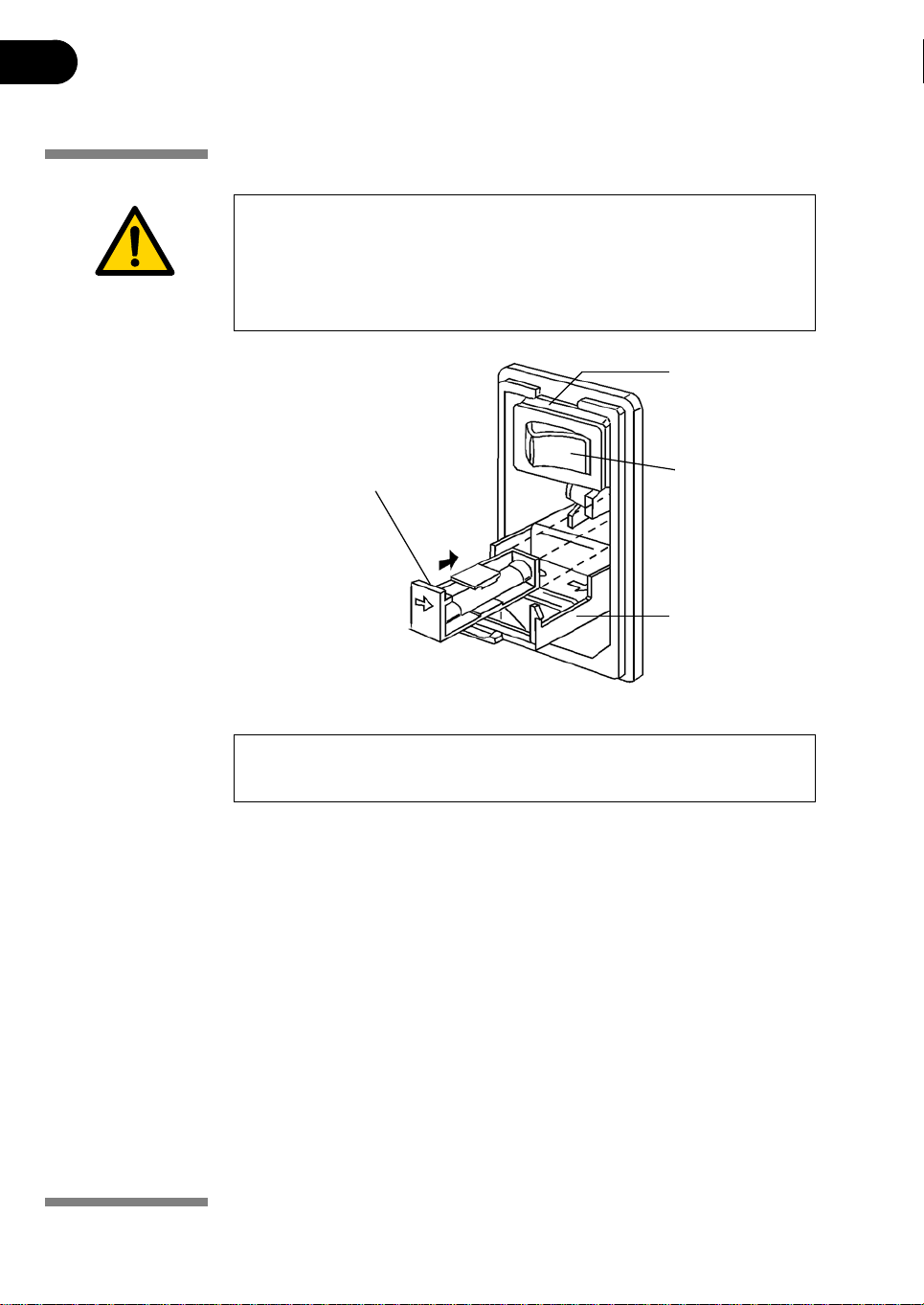
WARNING! Fuses protect equipment by disconnecting loads too large for the
instrument’s circuit design, so it is imperative that fuses are replaced only with
fuses of identical rating. The mains power module, located at the back of the
instrument, contains two input mains fuses which ar e the same for all models:
T2.5 AL 250V, 5
× 20 mm.
insert the
screwdriver blade
behind the arrow
to pull the cassette
completely out.
insert screwdriver
in this notch to
open the cover.
mains power
switch
hinged cover
Fig 4-1. The mains power module is located on the rear panel.
CAUTION! Turn the mains power supply switch off and det a ch the power cor d
before replacing input mains fuses!
To replace the fuse:
1 Open th e fuse compartment by inserting a small flat-blade screwdriver into
the slot at the top of the power module. Twist the screwdriver 1/8 – turn to
release the cover, then pull out the hinged compartment, which opens out.
2 Insert the screwdriver above the arrow on one fuse cassette, catch the
cassette end, and slowly slide it completely out of the module.
3 Pull the fuse out of its cassette and inspect. If the fuse element is burned or
broken, replace the fuse with an identical type. If the fuse appears to be
intact, check it with a multi-meter. (A reading of 1 ohm or less indicates the
fuse is still usable.)
4 After placing a good fuse into the cassette, slide it into the power module,
making sure the arrow on the cassette points to the right (in the same
direction as the guide arrows on the inside of the compartment door).
52 Ettan IPGphor 3 Instrument User Manual 11-0034-58 Edition AB
Page 53

Care and maintenance 4
5 Repeat steps 3 to 5 for the second cassette. 6 Close th e fuse compartment cover and gent ly press it into the power module
until it snaps shut.
7 Plug the power cord into the unit and turn the mains power switch on.
8 If the in strument does not start when power is s witched on after replacement
of mains fuse(s), call GE Healthcare service.
Ettan IPGphor 3 Instrument User Manual 11-0034-58 Edition AB 53
Page 54

4 Care and maintenance
54 Ettan IPGphor 3 Instrument User Manual 11-0034-58 Edition AB
Page 55
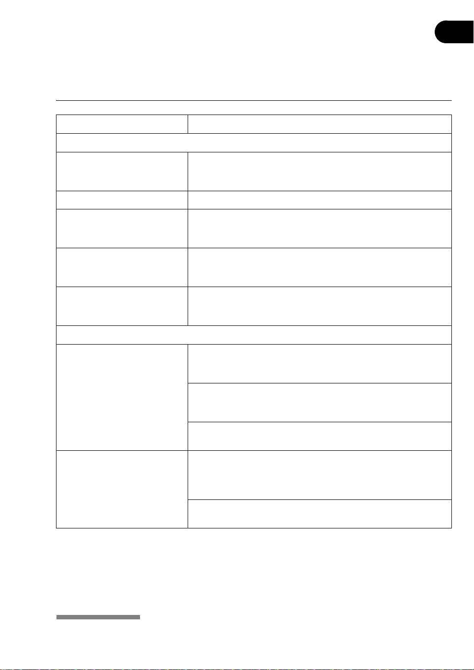
Troubleshooting 5
5 Troubleshooting
Symptom Possible solution
Problems indicated by LCD messages
Lid open step 1, close to continue The safety lid is not properly closed. When the safety lid is open, the
system has an automatic voltage cutoff safety feature. In order for the
protocol to proceed, the safety lid must be closed.
Locked screen in edit mode Turn off the mains power switch to reset the instrument.
Blank display If no electrical components are functioning (e.g. HV lamp does not light
and the cooling fans are motionless), check the fuses in the mains
power module.
Diagnostic program indicates
component failure
Arc An electric arc has been detected. The instrument will reduce the
Note the component that failed and press the
through the diagnostic program. Call your local GE Healthcare service
for further information on how to remedy the failure.
voltage setting 500 volts automatically. The run continues, and there is
no need for further action.
START key to continue
Power delivery
Current too low or zero At least two of three pressure pads under the safety lid should press
gently against the strip holders to ensure electrical continuity between
the strip holder electrodes and the electrode areas on the platform.
The gel must be evenly and completely rehydrated to conduct current.
Make sure the proper amount of rehydration solution is applied to the
IPG strip holder and allow a minimum of 10 hours for rehydration.
Check that both connecting points of the strip holder or the connecting
pins of the manifold electrodes are in contact with the gold surface.
Voltage limit not reached The ionic strength of the rehydration solution is too high. The instrument
has reached the current limit; reduce the IPG buffer concentration; use a
mixed-bed ion-exchange resin to remove ionic breakdown products of
urea of other additives.
Desalt the sample or prepare the sample so that the salt concentration
is less than 10 mM.
Ettan IPGphor 3 Instrument User Manual 11-0034-58 Edition AB 55
Page 56
5 Troubleshooting
Symptom Possible solution
Sparks or burning in strips Reduce the current limit. Do not exceed 50 µA per strip.
Prevent the IPG strip from drying out by always applying Immobiline
DryStrip Cover Fluid during rehydration.
Ensure that the IPG strip is fully rehydrated along the entire length of
the strip. The IPG strip should be in complete contact with the correct
volume of rehydration solution. Remove any air bubbles trapped under
the IPG strip.
Desalt the sample or prepare the sample so that the salt concentration
is less than 10 mM. De-ionize additives to the rehydration solution.
Excessive charged material in the sample or rehydration buffer lead to
electro-endosmosis which will dry out the middle of the strip, possibly
leading to arcing and burning at these points.
56 Ettan IPGphor 3 Instrument User Manual 11-0034-58 Edition AB
Page 57
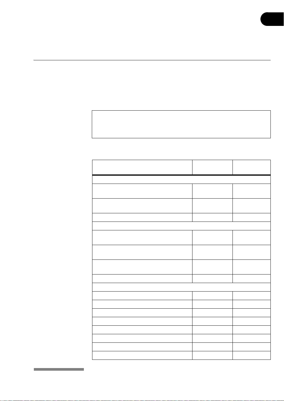
6 Customer service information
6.1 Technical service and repair
GE Healthcare offers complete technical support for all our products. If you have
any questions about how to use this product, or would like to arrange to repair it,
please call or fax your local GE Healthcare representative.
IMPORTANT! Request a copy of the GE Healthcare “Health and Safety
Declaration” form before returning the item. No items can be accepted for
servicing or return unless this form is pro pe r ly completed.
6.2 Ordering information
Product Quantity Code
Ettan IPGphor 3 Isoelectric Focusing Unit
Basic unit. Order manifold and strip holders
separately
Cable Serial 9 Pin F/F with Null Modem
Adapter
Ettan IPGphor 3 Control software 1 11-0036-23
Manifolds
Ettan IPGphor Cup Loading Manifold
ceramic, complete
Ettan IPGphor Cup Loading Manifold
ceramic
Ettan IPGphor Cup Loading Manifold Light,
complete
Ettan IPGphor Cup Loading Manifold Light 1 11-0025-80
Accessories
Sample cups pack of 20 (6
Paper electrode wicks pack of 40 (6
Paper bridge pads pack of 20 (6
Electrode set 1 80-6498-76
Lid adapter 1 28-4008-41
Cleaning brush 1 80-6505-98
Spirit level 1 80-6194-19
Forceps SS 1 80-6506-17
Customer service information 6
number
1 11-0033-64
1 80-6506-36
1 80-6498-38
1 80-6498-57
1 11-0026-88
×) 80-6498-95
×) 80-6499-14
×) 80-6499-33
Ettan IPGphor 3 Instrument User Manual 11-0034-58 Edition AB 57
Page 58

6 Customer service information
Product Quantity Code
USB-RS232 converter 1 28-4001-45
Strip holder covers
7 cm 2 80-6455-44
11 cm 2 80-6455-63
13 cm 2 80-6455-82
18 cm 2 80-6456-01
24 cm 2 80-6479-76
Strip holders for use with Immobiline DryStrip gels
7 cm, complete 6 80-6416-11
11 cm, complete 6 80-6416-30
13 cm, complete 6 80-6416-49
18 cm, complete 6 80-6416-68
24 cm, complete 6 80-6469-88
7 cm, complete 1 80-6416-87
11 cm, complete 1 80-6417-06
13 cm, complete 1 80-6417-25
18 cm, complete 1 80-6417-44
24 cm, complete 1 80-6470-07
Immobiline DryStrip Reswelling Trays
7–18 cm 1 80-6371-84
7–24 cm 1 80-6465-32
IPG Buffer
pH 3–10 L 1 ml 17-6000-87
pH 3–10 NL 1 ml 17-6000-88
pH 3–11 NL 1 ml 17-6004-40
pH 3.5–5.0 1 ml 17-6002-02
pH 4–7 1 ml 17-6000-86
pH 4.5–5.5 1 ml 17-6002-04
pH 5.0–6.0 1 ml 17-6002-05
pH 5.5–6.7 1 ml 17-6002-06
pH 6–11 1 ml 17-6001-78
pH 7–11 NL 1 ml 17-6004-39
Rehydration Solutions
DeStreak Rehydration Solution 1 ml 17-6003-19
DeStreak Reagent 5
number
× 3 ml 17-6003-18
58 Ettan IPGphor 3 Instrument User Manual 11-0034-58 Edition AB
Page 59

Customer service information 6
Product Quantity Code
number
Ettan preparation kits and reagents
2-D Fractionation Kit 10 preps 80-6501-04
Albumin and 1gG Removal Kit 10 preps RPN6300
Protease Inhibitor 1 ml 80-6501-23
Nuclease Mix 0.5 ml 80-6501-42
Thiourea 100 g RPN6301
Iodoacetamide 25 g RPN6302
Sample Grinding Kit 50 samples 80-6483-37
2-D Clean-Up Kit 50 samples 80-6484-51
SDS-PAGE Clean-Up Kit 50 samples 80-6484-70
2-D Quant Kit 500 assays 80-6483-56
Mini Dialysis Kit, 1 kDa cut-off, 250 µl 1 80-6483-75
Mini Dialysis Kit, 1 kDa cut-off, 2 ml 1 80-6483-94
Mini Dialysis Kit, 8 kDa cut-off, 250 µl 1 80-6484-13
Mini Dialysis Kit, 8 kDa cut-off, 2 ml 1 80-6484-32
PlusOne™ reagents
Urea 500 g 17-1319-01
CHAPS 1 g 17-1314-01
Triton™ X-100 500 ml 17-1315-01
Dithiothreitol (DTT) 1 g 17-1318-01
Bromophenol Blue 10 g 17-1329-01
Immobiline DryStrip Cover Fluid 1000 ml 17-1335-01
Immobiline DryStrip gels
7 cm
pH 3–5.6 12 17-6003-53
pH 3–10 12 17-6001-11
pH 3–10NL 12 17-6001-12
pH 3–11 NL 12 17-6003-73
pH 4–7 12 17-6001-10
pH 5.3–6.5 12 17-6003-58
pH 6–11 12 17-6001-94
pH 6.2–7.5 12 17-6003-63
pH 7–11 NL 12 17-6003-68
Ettan IPGphor 3 Instrument User Manual 11-0034-58 Edition AB 59
Page 60

6 Customer service information
Product Quantity Code
11 cm
pH 3–5.6 12 17-6003-54
pH 3–10 12 18-1016-61
pH 3–11 NL 12 17-6003-74
pH 4–7 12 18-1016-60
pH 5.3–6.5 12 17-6003-59
pH 6–11 12 17-6001-95
pH 6.2–7.5 12 17-6003-64
pH 7–11 NL 12 17-6003-69
13 cm
pH 3–5.6 12 17-6003-55
pH 3–10 12 17-6001-14
pH 3–10NL 12 17-6001-15
pH 3–11 NL 12 17-6003-75
pH 4–7 12 17-6001-13
pH 5.3–6.5 12 17-6003-60
pH 6–11 12 17-6001-96
pH 6.2–7.5 12 17-6003-65
pH 7–11 NL 12 17-6003-70
18 cm
pH 3–5.6 12 17-6003-56
pH 3–10 12 17-1234-01
pH 3–10NL 12 17-1235-01
pH 3–11 NL 12 17-6003-76
pH 3.5–4.5 12 17-6001-83
pH 4–7 12 17-1233-01
pH 4.0–5.0 12 17-6001-84
pH 4.5–5.5 12 17-6001-85
pH 5.0–6.0 12 17-6001-86
pH 5.3–6.5 12 17-6003-61
pH 5.5–6.7 12 17-6001-87
pH 6–9 12 17-6001-88
pH 6–11 12 17-6001-97
pH 6.2–7.5 12 17-6003-66
pH 7–11 NL 12 17-6003-71
number
60 Ettan IPGphor 3 Instrument User Manual 11-0034-58 Edition AB
Page 61

Customer service information 6
Product Quantity Code
number
24 cm
pH 3–5.6 NL 12 17-6003-57
pH 3–7 NL 12 17-6002-43
pH 3–10 12 17-6002-44
pH 3–10 NL 12 17-6002-45
pH 3–11 NL 12 17-6003-77
pH 3.5–4.5 12 17-6002-38
pH 4.0–5.0 12 17-6002-39
pH 4–7 12 17-6002-46
pH 4.5–5.5 12 17-6002-40
pH 5.0–6.0 12 17-6002-41
pH 5.3–6.5 12 17-6003-62
pH 5.5–6.7 12 17-6002-42
pH 6–9 12 17-6002-47
pH 6.2–7.5 12 17-6003-67
pH 7–11 NL 12 17-6003-72
Cleaning solution, IPGphor Strip Holder 950 ml 80-6452-78
2-D Electrophoresis Principles and Methods 1 80-6429-60
Equilibration tube set for 24 cm IPG Strips 12 80-6467-79
IEF electrode strips 100 18-1004-40
Immobiline DryStrip Cover Fluid 1 liter 17-1335-01
Ettan IPGphor 3 Instrument User Manual 11-0034-58 Edition AB 61
Page 62

6 Customer service information
62 Ettan IPGphor 3 Instrument User Manual 11-0034-58 Edition AB
Page 63

Page 64

www.gehealthcare.com
GE Healthcare Bio-Sciences AB
Björkgatan 30
751 84 Uppsala
Sweden
Asia Paci.c Tel: +852 2811 8693 Fax: +852 2811 5251 • Australasia Tel: + 61 2 9899 0999 Fax: +61 2 9899 7511 • Austria Tel: 01/57606-1619 Fax: 01/57606-1627 • Belgium Tel: 0800 73 888
Fax: 03 272 1637 • Canada Tel: 800 463 5800 Fax: 800 567 1008 • Central, East, & South East Europe Tel: +43 1 982 3826 Fax: +43 1 985 8327 • Denmark Tel: 45 16 2400 Fax: 45 16 2424 • Finland &
Baltics Tel: +358-(0)9-512 39 40 Fax: +358 (0)9 512 39 439 • France Tel: 01 69 35 67 00 Fax: 01 69 41 96 77 • Germany Tel: 0761/4903-490 Fax: 0761/4903-405 • Italy Tel: 02 27322 1 Fax: 02 27302 212
• Japan Tel: +81 3 5331 9336 Fax: +81 3 5331 9370 • Latin America Tel: +55 11 3933 7300 Fax: +55 11 3933 7304 • Middle East & Africa Tel: +30 210 9600 687 Fax: +30 210 9600 693 • Netherlands
Tel: 0165 580 410 Fax: 0165 580 401 • Norway Tel: 815 65 555 Fax: 815 65 666 • Portugal Tel: 21 417 7035 Fax: 21 417 3184 • Russia & other C.I.S. & N.I.S Tel: +7 (095) 232 0250, 956 1137 Fax: +7 (095)
230 6377 • South East Asia Tel: 60 3 8024 2080 Fax: 60 3 8024 2090 • Spain Tel: 93 594 49 50 Fax: 93 594 49 55 • Sweden Tel: 018 612 1900 Fax: 018 612 1910 • Switzerland Tel: 0848 8028 12 Fax:
0848 8028 13 • UK Tel: 0800 616928 Fax: 0800 616927 • USA Tel: 800 526 3593 Fax: 877 295 8102
Ettan, CyDye, Immobiline, IPGphor, and PlusOne are trademarks of GE
Healthcare Ltd. GE tagline and GE monogram are trademarks of General
Electric Company.
Triton is a trademark of Union Chemicals and Plastics Co.
Windows is a trademark of Microsoft Corporation.
All goods and services are sold subject to the terms and conditions of sale of
the company within GE Healthcare which supplies them. GE Healthcare
reserves the right, subject to any regulatory and contractual approval, if
required, to make changes in specifications and features shown herein, or
discontinue the product described at any time without notice or obligation.
Contact your local GE Healthcare representative for the most current
information.
© 2005 General Electric Company – All rights reserved.
GE Healthcare Bio-Sciences AB, a General Electric company.
GE Healthcare
Munzinger Strasse 9, D-79111 Freiburg, Germany
GE Healthcare
Amersham Place, Little Chalfont, Bucki nghamshire, HP7 9NA, UK
GE Healthcare
800 Centennial Avenue, P.O. Box 1327, Piscataway, NJ 08855-1327, USA
GE Healthcare
Sanken Bldg. 3-25-1, Hyakunincho, Shinjuku-ku, Tokyo 169-0073, Japan
imagination at work
Instrument User Manual 11-0034-58 AB
 Loading...